EP2492471B1 - Gasturbinenmotorrekuperator mit schwebender Verbindung - Google Patents
Gasturbinenmotorrekuperator mit schwebender Verbindung Download PDFInfo
- Publication number
- EP2492471B1 EP2492471B1 EP12157320.8A EP12157320A EP2492471B1 EP 2492471 B1 EP2492471 B1 EP 2492471B1 EP 12157320 A EP12157320 A EP 12157320A EP 2492471 B1 EP2492471 B1 EP 2492471B1
- Authority
- EP
- European Patent Office
- Prior art keywords
- exhaust
- inlet
- outlet
- gas turbine
- turbine engine
- Prior art date
- Legal status (The legal status is an assumption and is not a legal conclusion. Google has not performed a legal analysis and makes no representation as to the accuracy of the status listed.)
- Active
Links
Images


Classifications
-
- F—MECHANICAL ENGINEERING; LIGHTING; HEATING; WEAPONS; BLASTING
- F02—COMBUSTION ENGINES; HOT-GAS OR COMBUSTION-PRODUCT ENGINE PLANTS
- F02C—GAS-TURBINE PLANTS; AIR INTAKES FOR JET-PROPULSION PLANTS; CONTROLLING FUEL SUPPLY IN AIR-BREATHING JET-PROPULSION PLANTS
- F02C7/00—Features, components parts, details or accessories, not provided for in, or of interest apart form groups F02C1/00 - F02C6/00; Air intakes for jet-propulsion plants
- F02C7/08—Heating air supply before combustion, e.g. by exhaust gases
-
- F—MECHANICAL ENGINEERING; LIGHTING; HEATING; WEAPONS; BLASTING
- F28—HEAT EXCHANGE IN GENERAL
- F28D—HEAT-EXCHANGE APPARATUS, NOT PROVIDED FOR IN ANOTHER SUBCLASS, IN WHICH THE HEAT-EXCHANGE MEDIA DO NOT COME INTO DIRECT CONTACT
- F28D21/00—Heat-exchange apparatus not covered by any of the groups F28D1/00 - F28D20/00
- F28D21/0001—Recuperative heat exchangers
- F28D21/0003—Recuperative heat exchangers the heat being recuperated from exhaust gases
- F28D21/001—Recuperative heat exchangers the heat being recuperated from exhaust gases for thermal power plants or industrial processes
-
- F—MECHANICAL ENGINEERING; LIGHTING; HEATING; WEAPONS; BLASTING
- F28—HEAT EXCHANGE IN GENERAL
- F28D—HEAT-EXCHANGE APPARATUS, NOT PROVIDED FOR IN ANOTHER SUBCLASS, IN WHICH THE HEAT-EXCHANGE MEDIA DO NOT COME INTO DIRECT CONTACT
- F28D9/00—Heat-exchange apparatus having stationary plate-like or laminated conduit assemblies for both heat-exchange media, the media being in contact with different sides of a conduit wall
- F28D9/0012—Heat-exchange apparatus having stationary plate-like or laminated conduit assemblies for both heat-exchange media, the media being in contact with different sides of a conduit wall the apparatus having an annular form
- F28D9/0018—Heat-exchange apparatus having stationary plate-like or laminated conduit assemblies for both heat-exchange media, the media being in contact with different sides of a conduit wall the apparatus having an annular form without any annular circulation of the heat exchange media
-
- F—MECHANICAL ENGINEERING; LIGHTING; HEATING; WEAPONS; BLASTING
- F28—HEAT EXCHANGE IN GENERAL
- F28F—DETAILS OF HEAT-EXCHANGE AND HEAT-TRANSFER APPARATUS, OF GENERAL APPLICATION
- F28F9/00—Casings; Header boxes; Auxiliary supports for elements; Auxiliary members within casings
- F28F9/02—Header boxes; End plates
- F28F9/0236—Header boxes; End plates floating elements
-
- F—MECHANICAL ENGINEERING; LIGHTING; HEATING; WEAPONS; BLASTING
- F28—HEAT EXCHANGE IN GENERAL
- F28F—DETAILS OF HEAT-EXCHANGE AND HEAT-TRANSFER APPARATUS, OF GENERAL APPLICATION
- F28F9/00—Casings; Header boxes; Auxiliary supports for elements; Auxiliary members within casings
- F28F9/26—Arrangements for connecting different sections of heat-exchange elements, e.g. of radiators
-
- F—MECHANICAL ENGINEERING; LIGHTING; HEATING; WEAPONS; BLASTING
- F05—INDEXING SCHEMES RELATING TO ENGINES OR PUMPS IN VARIOUS SUBCLASSES OF CLASSES F01-F04
- F05D—INDEXING SCHEME FOR ASPECTS RELATING TO NON-POSITIVE-DISPLACEMENT MACHINES OR ENGINES, GAS-TURBINES OR JET-PROPULSION PLANTS
- F05D2220/00—Application
- F05D2220/30—Application in turbines
- F05D2220/32—Application in turbines in gas turbines
- F05D2220/323—Application in turbines in gas turbines for aircraft propulsion, e.g. jet engines
-
- F—MECHANICAL ENGINEERING; LIGHTING; HEATING; WEAPONS; BLASTING
- F05—INDEXING SCHEMES RELATING TO ENGINES OR PUMPS IN VARIOUS SUBCLASSES OF CLASSES F01-F04
- F05D—INDEXING SCHEME FOR ASPECTS RELATING TO NON-POSITIVE-DISPLACEMENT MACHINES OR ENGINES, GAS-TURBINES OR JET-PROPULSION PLANTS
- F05D2230/00—Manufacture
- F05D2230/60—Assembly methods
- F05D2230/64—Assembly methods using positioning or alignment devices for aligning or centring, e.g. pins
- F05D2230/642—Assembly methods using positioning or alignment devices for aligning or centring, e.g. pins using maintaining alignment while permitting differential dilatation
-
- F—MECHANICAL ENGINEERING; LIGHTING; HEATING; WEAPONS; BLASTING
- F28—HEAT EXCHANGE IN GENERAL
- F28F—DETAILS OF HEAT-EXCHANGE AND HEAT-TRANSFER APPARATUS, OF GENERAL APPLICATION
- F28F21/00—Constructions of heat-exchange apparatus characterised by the selection of particular materials
- F28F21/08—Constructions of heat-exchange apparatus characterised by the selection of particular materials of metal
- F28F21/081—Heat exchange elements made from metals or metal alloys
- F28F21/087—Heat exchange elements made from metals or metal alloys from nickel or nickel alloys
-
- F—MECHANICAL ENGINEERING; LIGHTING; HEATING; WEAPONS; BLASTING
- F28—HEAT EXCHANGE IN GENERAL
- F28F—DETAILS OF HEAT-EXCHANGE AND HEAT-TRANSFER APPARATUS, OF GENERAL APPLICATION
- F28F2230/00—Sealing means
-
- F—MECHANICAL ENGINEERING; LIGHTING; HEATING; WEAPONS; BLASTING
- F28—HEAT EXCHANGE IN GENERAL
- F28F—DETAILS OF HEAT-EXCHANGE AND HEAT-TRANSFER APPARATUS, OF GENERAL APPLICATION
- F28F2265/00—Safety or protection arrangements; Arrangements for preventing malfunction
- F28F2265/26—Safety or protection arrangements; Arrangements for preventing malfunction for allowing differential expansion between elements
-
- Y—GENERAL TAGGING OF NEW TECHNOLOGICAL DEVELOPMENTS; GENERAL TAGGING OF CROSS-SECTIONAL TECHNOLOGIES SPANNING OVER SEVERAL SECTIONS OF THE IPC; TECHNICAL SUBJECTS COVERED BY FORMER USPC CROSS-REFERENCE ART COLLECTIONS [XRACs] AND DIGESTS
- Y10—TECHNICAL SUBJECTS COVERED BY FORMER USPC
- Y10T—TECHNICAL SUBJECTS COVERED BY FORMER US CLASSIFICATION
- Y10T29/00—Metal working
- Y10T29/49—Method of mechanical manufacture
- Y10T29/49716—Converting
Definitions
- the application relates generally to a recuperator for a gas turbine engine and, more particularly, to such a recuperator allowing for a reduction of thermal stresses therein.
- Gas turbine engines may include a recuperator, which is a heat exchanger using hot exhaust gas from the engine to heat the compressed air exiting the compressor prior to circulation of the compressed air to the combustion chamber. Preheating the compressed air usually improves fuel efficiency of the engine.
- the recuperator reduces the heat of exhaust gas, which helps minimize the infrared signature of the aircraft.
- recuperator structures are also relatively heavy and/or costly to manufacture, and as such generally unsuitable for aircraft use.
- US 5,004,044 discloses a prior art gas turbine engine according to the preamble of claim 1, a prior art recuperator according to the preamble of claim 8, and a prior art method according to the preamble of claim 11.
- the method may further comprise a preliminary step of detaching and removing an exhaust scroll of the gas turbine engine, the segment being installed through an opening previously covered by the exhaust scroll.
- Engaging the air outlet may include forming the rigid connection and engaging the air inlet may include forming the floating connection.
- the method further comprises positioning a control surface of the segment against a wall of the exhaust duct without impeding relative movement therebetween.
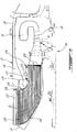
- Fig.1 illustrates a gas turbine engine 10 of a type preferably provided for use in subsonic flight, generally comprising in serial flow communication a fan 12 through which ambient air is propelled, a compressor section 14 for pressurizing the air, a combustor 16 in which the compressed air is mixed with fuel and ignited for generating an annular stream of hot combustion gases, and a turbine section 18 for extracting energy from the combustion gases.
- the compressor section 14 and combustor 16 are typically in serial flow communication with one another through a gas generator case 22 which contains the combustor 16 and which receives the flow from the compressor discharge, which in the embodiment shown is in the form of diffuser pipes 20.
- the combustion gases flowing out of the combustor 16 circulate through the turbine section 18 and are then expelled through an exhaust duct 24.
- gas turbine engine 10 may alternately be another type of engine, for example a turboshaft engine, also generally comprising in serial flow communication a compressor section, a combustor, and a turbine section, and a propeller shaft supporting a propeller and rotated by a low pressure portion of the turbine section through a reduction gearbox.
- a turboshaft engine also generally comprising in serial flow communication a compressor section, a combustor, and a turbine section, and a propeller shaft supporting a propeller and rotated by a low pressure portion of the turbine section through a reduction gearbox.
- the gas generator case 22 is separated in at least two plenums, including a plenum 26 containing the combustor 16, and another plenum 28 in fluid flow communication with the diffuser pipes 20 of the compressor section 14.
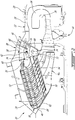
- a recuperator 30 extends across the exhaust duct 24, such that the exhaust gas from the turbine section 18 circulates therethrough.
- the recuperator 30 also provides the fluid flow communication between the combustor plenum 26 and the compressor plenum 28, as will be further detailed below.
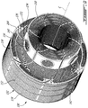
- the recuperator 30 includes a plurality of arcuate segments 32, which function independently from one another and are connected to the engine 10 independently from one another, and which together define the annular shape of the recuperator 30.
- a controlled gap 34 (see Fig. 4 ) is provided between adjacent ones of the segments 32 to allow for thermal expansion without interference.
- the segments 32 are sized to extend between adjacent structural struts 36 (see Fig. 3 ) of the engine 10, and as such the gap 34 is sized to allow for thermal expansion of each segment 32 without major interference with the strut 36 extending in the gap 34.
- a compressible side plate 46 at the side of the segment 32 provides sealing with the strut 36 and vibrational damping during engine operation.
- each segment 32 is sized and located such as to be removable from the outside of the engine 10 through an opening accessible when the exhaust scroll 38 (see Fig. 2 ) is removed.
- the exhaust scroll 38 that is removable on the wing, such a configuration allows for the recuperator segments 32 to be removed and replaced if necessary with the engine 10 remaining on the wing.
- each segment 32 defines a plate heat exchanger, with a first group of fluid passages 40 for circulating the compressed air, and a second group of fluid passages 42 for circulating the exhaust gas.
- the air and exhaust passages 40, 42 alternate and are in heat transfer relationship with one another.
- the air and exhaust passages 40, 42 are relatively oriented such as to define a mixed counter flow and double pass cross flow heat exchanger.
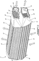
- a panel assembly 44 thus defines the alternating U-shaped first fluid passages 40 and curved second fluid passages 42.
- the panels 44 are made of a nickel alloy and are brazed to one another.
- the side plates 46 and a rear bulkhead 48 respectively seal the opposed side ends and the rear end of the panel assembly 44.
- the bulkhead 48 also provides vibrational damping of the segment 32 during engine operation.
- the exhaust fluid passages 42 communicate with a same exhaust inlet 50 defined by the radially inward end of the segment 32 and with a same exhaust outlet 52 defined by the radially outward end of the segment 32.
- the exhaust inlet and outlet 50, 52 extend across the exhaust duct 24, with the exhaust inlet 50 located in proximity of the turbine section 18.
- the air passages 40 communicate with a same air inlet 56 defined at one end thereof and with a same air outlet 72 defined at the opposed end thereof.
- the air inlet 56 is defined by an inlet connection member 58 which is designed to sealingly engage the compressor plenum 28 for receiving the compressed air.
- the air inlet 56 is oriented such that the compressed air flows axially or approximately axially therethrough.
- the inlet connection member 58 includes a duct 60 having one end connected to an inlet bulkhead 62 attached to the panel assembly 44, and an opposed end having a flange 64 extending outwardly therearound. Referring to Fig.
- the inlet connection member 58 also includes a flexible duct member 66 having a first end rigidly connected to the flange 64, for example through an appropriate type of fasteners with a compressible seal ring or a gasket (not shown) therebetween. A second end of the flexible duct member 66 is rigidly connected to the compressor plenum 28.
- the flexible duct member 66 includes two rigid duct portions 68 interconnected by a diaphragm 70, which allows relative movement between the two duct portions 68; alternately, the entire flexible duct member 66 may be made of flexible material.
- flexible duct member is intended herein to designate a duct member which includes at least a flexible portion such as to allow for relative movement between its opposed ends.
- the inlet connection member 58 thus defines a floating connection with the compressor plenum 28, such that some amount of axial and radial relative motion is allowed therebetween.
- the air outlet 72 is defined by an outlet connection member 74 which is designed to sealingly engage the combustor plenum 26 for delivering the heated compressed air to the combustor 16.
- the air outlet 72 is oriented such that the heated compressed air flows axially or approximately axially therethrough.
- the outlet connection member 74 includes a duct 76 having one end connected to an outlet bulkhead 78 attached to the panel assembly 44, and an opposed end having a flange 80 extending outwardly therearound.
- the flange 80 is rigidly connected to the combustor plenum 26, for example through an appropriate type of fasteners.
- a compressible seal ring or a gasket (not shown) is received between the flanged 80 and the plenum 26 to form a sealed connection.
- the outlet connection member 74 thus defines a rigid connection with the combustor plenum 26.
- the inlet connection member 58 may define a rigid connection with the compressor plenum 28, with the outlet connection member 74 defining a floating connection with the combustor plenum 26.
- the rear bulkhead 48 includes a protrusion 82 which is designed to be the contact point between the segment 32 and the wall 84 of the exhaust duct 24, in order to stabilize the position of the segment 32 within the exhaust duct 24.
- the protrusion 82 facilitates the relative sliding motion between the rear bulkhead 48 and the exhaust duct wall 84 when relative movement due to the floating connection occurs, and acts as a control surface maintaining contact between the segment 32 and the exhaust duct wall 84.
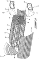
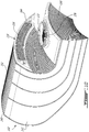
- the exhaust passages 42 have a flaring shape, i.e. the cross-sectional area of each exhaust passage 42 increases from the exhaust inlet 50 to the exhaust outlet 52, such as to diffuse the exhaust flow.
- the exhaust inlet 50 thus has a smaller cross-sectional area than that of the exhaust outlet 52.
- a concentric split diffuser 53 is provided in the exhaust duct 24 upstream of the exhaust inlet 50.
- the diffuser 53 includes circumferential splitters 54 which are supported by radial struts 55.
- the splitters 54 progressively curve from the axial direction at the upstream end toward the radial direction.
- the splitters 54 define passages having a flaring shape, i.e.
- Diffuser vanes 51 may also be provided at the exit of the power turbine, upstream of the split diffuser 53. The diffusion of the exhaust flow allows for an improved heat exchange within the recuperator 30.
- the concentric split diffuser 53' including splitters 53' and radial struts 55' forms part of the recuperator 30, and extends from the exhaust inlet 50.
- the recuperator 30 also reduces the swirl of the exhaust flow.
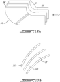
- the exhaust passages 42 have an arcuate profile in a plane perpendicular to a central axis C of the recuperator to reduce the exhaust flow swirl.
- the splitters 54 ( Fig. 2 ) may also be curved in the plane perpendicular to the central axis of the recuperator.
- the radial struts 55, 55' which are structural members supporting the splitters 54, 54' ( Figs. 2 and 7 ) have an asymmetrical airfoil shape twisted to allow a progressively increased swirl with increasing radius, optimised to reduce the turning losses as the flow turns from the axial to the radial direction within the diffuser 53, 53'.
- the vanes 51 may also have an asymmetrical airfoil shape similar to the struts 55, 55'.
- the swirl i.e. the circumferential component of the flow velocity at the power turbine exit, is thus first slowed in the diffuser vanes 51.
- the flow exiting the vanes 51 enter the split diffuser 53, 53'.
- the flow in the split diffuser 53, 53' slows down both in the axial direction due to the splitters 54, 54' as well as in circumferential direction, i.e. the swirl, due to the increased radius of the swirling shape of the radial struts 55, 55'.
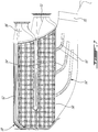
- the recuperator 130 includes a plurality of independent arcuate segments 132, with a controlled gap 134 being defined between adjacent segments 132 for thermal expansion.
- Each segment 132 defines a plate heat exchanger, with a first group of fluid passages 140 for circulating the compressed air, and a second group 142 of fluid passages for circulating the exhaust gas, alternating and in heat transfer relationship with one another.
- the recuperator 130 extends within the exhaust duct 24 closer to the turbine section 18 than the previously described embodiment.
- Each segment 132 includes an exhaust inlet 150 defined by a radially extending end of the segment 132 located in proximity of the turbine section 18 and in communication with the exhaust passages 142.
- the exhaust inlet 150 is oriented such that the exhaust gas flows axially or approximately axially therethrough.
- Each segment 132 also includes an exhaust outlet 152 in communication with exhaust passages 142, and oriented such that the exhaust gas flows outwardly radially or approximately outwardly radially therethrough.
- the air passages 140 communicate with a same air inlet 156 defined at one end thereof and with a same air outlet 172 defined at the opposed end thereof.
- the air inlet 156 is defined by an inlet connection member 158 which is designed to sealingly engage the compressor plenum 28 for circulating the compressed air.
- the air inlet 156 is oriented such that the compressed air flows axially or approximately axially therethrough.
- the inlet connection member 158 includes a support 164 surrounding the inlet 156 which is rigidly connected to the compressor plenum 28, for example through an appropriate type of fasteners with a compressible seal ring or a gasket (not shown) therebetween.
- the inlet connection member 158 thus defines a rigid connection with the compressor plenum 28.
- the air outlet 172 is defined by an outlet connection member 174 which is designed to sealingly engage the combustor plenum 26 for delivering the heated compressed air to the combustor 16.
- the air outlet 172 is oriented such that the heated compressed air flows radially outwardly or approximately radially outwardly therethrough.
- the outlet connection member 174 includes a duct 176 which is engaged in a corresponding opening of the combustor plenum 26.
- a flexible and compressible circular seal 94 for example having a C-shaped cross-section, surrounds the duct 176 and abuts the wall 98 of the plenum 26 around the opening where the duct 176 is received.
- connection member 174 thus defines a floating connection with the combustor plenum 26, as some amount of axial and tangential relative motion is allowed between the connection member 174 and the support opening of the plenum 26 to compensate for thermal mismatch.
- the circular seal 94 seals the connection.
- the exhaust passages 142 defined between the air cells 141 forming the air passages 140, have a flaring shape such as to diffuse the exhaust flow.
- the exhaust inlet 150 thus has a smaller cross-sectional area than that of the exhaust outlet 152.
- the diffusion of the exhaust flow allows for an improved heat exchange within the recuperator 130.
- the recuperator 130 has a shape substantially confirming to that of the exhaust duct 24, with a controlled gap 134 (see Fig. 11 ) being provided between the recuperator 130 and exhaust duct wall to prevent restriction of the relative movement allowed by the floating connection.
- the recuperator 130 also reduces the swirl of the exhaust flow.
- the air cells 141 forming the exhaust passages 142 act as vanes, and have an arcuate profile in a plane perpendicular to a central axis C of the recuperator to reduce the exhaust flow swirl.
- the air cells 141 thus define a diffusion area 99 and a deswirling and diffusion area 100, which act to slow down the exhaust flow both in the axial direction as well as in circumferential direction.
- each segment 132 of the recuperator 130 is only connected to the engine 10 through the inlet and outlet connection members 158, 174, and the segments 132 are independent from each other. Since one of these connection members defines a floating connection, some relative movement is allowed between each segment 132 of the recuperator 130 and the remainder of the gas turbine engine 10, such as to accommodate some amount of thermal expansion without impeding the seal of the connections.
Landscapes
- Engineering & Computer Science (AREA)
- Mechanical Engineering (AREA)
- General Engineering & Computer Science (AREA)
- Physics & Mathematics (AREA)
- Thermal Sciences (AREA)
- Chemical & Material Sciences (AREA)
- Combustion & Propulsion (AREA)
- Heat-Exchange Devices With Radiators And Conduit Assemblies (AREA)
- Turbine Rotor Nozzle Sealing (AREA)
Claims (11)
- Gasturbinenmotor (10), umfassend:einen Verdichterabschnitt (14) mit einer Entladung in Fluidströmungsverbindung mit einer ersten Kammer (28);eine Brennkammer (16), die in einer zweiten Kammer (26) enthalten ist;einen Turbinenabschnitt (18) in Fluidströmungsverbindung mit der Brennkammer (16);eine Abgasleitung (24) in Fluidströmungsverbindung mit dem Turbinenabschnitt (18); undeinen Rekuperator (130), der in der Abgasleitung (24) angeordnet ist, wobei der Rekuperator eine Vielzahl von unabhängigen ringförmigen Segmenten (132) beinhaltet, wobei jedes Segment Folgendes definiert:Abgaskanäle (142), die eine Fluidströmungsverbindung zwischen einem Abgaseinlass (150) und einem Abgasauslass (152) bereitstellen, wobei sich der Abgaseinlass (150) und der Abgasauslass (152) über die Abgasleitung (24) erstrecken, wobei der Abgaseinlass (150) in Fluidströmungsverbindung mit dem Turbinenabschnitt (18) steht,Luftkanäle (140) in Wärmetauschbeziehung mit den Abgaskanälen (142), die eine Fluidströmungsverbindung zwischen einem Lufteinlass (156) und einem Luftauslass (172) bereitstellen,ein Einlassverbindungselement (158), das den Lufteinlass (156) definiert und in abdichtenden Eingriff mit der ersten Kammer (28) steht, um Druckluft von dem Verdichter (14) aufzunehmen, undein Auslassverbindungselement (174), das den Luftauslass (172) definiert und in abdichtenden Eingriff mit der die Brennkammer (18) enthaltenden zweiten Kammer (26) steht, wobei eines von dem Einlass- und dem Auslassverbindungselement (158, 174) eine starre Verbindung mit der entsprechenden von der ersten und der zweiten Kammer (26, 28) definiert, wobei das Einlass- und das Auslassverbindungselement (158, 174) die einzigen Verbindungen zwischen dem Segment (132) und einem Rest des Gasturbinenmotors (10) definieren,gekennzeichnet dadurch, dass:das andere von dem Einlass- und dem Auslassverbindungselement (158, 174) eine schwebende Verbindung definiert, die eine relative Bewegung zwischen dem anderen von dem Einlass- und dem Auslassverbindungselement (158, 174) und der entsprechenden von der ersten und der zweiten Kammer (26, 28) ermöglicht; unddas andere von dem Einlass- und dem Auslassverbindungselement eine Leitung (176) in Eingriff in einer Öffnung der entsprechenden von der ersten und der zweiten Kammer (26) beinhaltet, wobei die Leitung (176) einen Flansch (96), der in der entsprechenden von der ersten und der zweiten Kammer (26) aufgenommen ist und sich über einen Wandabschnitt (98) der entsprechenden von der ersten und der zweiten Kammer (26) erstreckt, der die Öffnung umgibt, sowie ein zusammendrückbares Element (94) aufweist, das zwischen dem Flansch (96) und dem Wandabschnitt (98) zusammengedrückt ist.
- Gasturbinenmotor nach Anspruch 1, wobei jedes Segment (132) des Rekuperators (130) ein Plattenwärmetauscher ist.
- Gasturbinenmotor nach Anspruch 1 oder 2, wobei das Auslassverbindungselement (74) die starre Verbindung und das Einlassverbindungselement (58) die schwebende Verbindung definiert.
- Gasturbinenmotor nach einem der vorhergehenden Ansprüche, wobei die schwebende Verbindung eine relative Bewegung zwischen dem anderen von dem Einlass- und dem Auslassverbindungselement (158, 174) und der entsprechenden von der ersten und der zweiten Kammer (26, 28) entlang einer axialen und einer radialen Richtung in Bezug auf eine Mittelachse des Gasturbinenmotors (10) ermöglicht.
- Gasturbinenmotor nach einem der vorhergehenden Ansprüche, wobei die schwebende Verbindung eine relative Bewegung zwischen dem anderen von dem Einlass- und dem Auslassverbindungselement (174) und der entsprechenden von der ersten und der zweiten Kammer (26) entlang einer axialen und einer tangentialen Richtung in Bezug auf eine Mittelachse des Gasturbinenmotors ermöglicht.
- Gasturbinenmotor nach einem der vorhergehenden Ansprüche, wobei jedes Segment (132) eine Steuerfläche (82) beinhaltet, die in Kontakt mit einer Wand (84) der Abgasleitung (24) steht, wobei sich die Steuerfläche (82) relativ zu der Wand (84) frei bewegen kann.
- Gasturbinenmotor nach einem der vorhergehenden Ansprüche, wobei der Motor (10) eine entfernbare Abgasspirale (38) beinhaltet, die mindestens teilweise den Rekuperator (130) innerhalb des Motors (10) umschließt, wobei das Einlass- und das Auslassverbindungselement (158, 174) jedes Segments (132) entfernbar mit der entsprechenden von der ersten und der zweiten Kammer (26, 28) verbunden ist, und wobei jedes Segment (132) derart bemessen ist, dass es aus dem Motor (10) durch eine Öffnung entfernt werden kann, die durch die Abgasspirale (38) geschlossen wird.
- Rekuperator (130), umfassend eine Vielzahl von unabhängigen bogenförmigen Segmenten (132), die dazu konfiguriert sind, sich innerhalb einer Abgasleitung (24) eines Gasturbinenmotors (10) zu erstrecken, wobei jedes Segment Folgendes beinhaltet:Abgaskanäle (142), die eine Fluidströmungsverbindung zwischen einem Abgaseinlass (150) und einem Abgasauslass (152) bereitstellen, wobei der Abgaseinlass (150) ausgerichtet ist, um einen Abgasstrom von einer Turbine (18) des Motors aufzunehmen, und der Abgasauslass (152) ausgerichtet ist, um den Abgasstrom an die Atmosphäre abzugeben;Luftkanäle (140) in Wärmetauschbeziehung mit den Abgaskanälen (142), die eine Fluidströmungsverbindung zwischen einem Lufteinlass (176) und einem Luftauslas (172) bereitstellen;ein Einlassverbindungselement (158), das den Lufteinlass (156) definiert und dazu ausgestaltet ist, in abdichtenden Eingriff mit einer ersten Kammer (28) in Fluidströmungsverbindung mit einer Verdichterentladung des Gasturbinenmotors (10) zu stehen; undein Auslassverbindungselement (174), das den Luftauslass (172) definiert und dazu ausgestaltet ist, in abdichtenden Eingriff mit einer einen Verdichter (16) enthaltenden zweiten Kammer (26) des Gasturbinenmotors (10) zu stehen, wobei eines von dem Einlass- und dem Auslassverbindungselement (158, 174) ein starres Element ist, das eine starre Verbindung mit der jeweiligen Kammer (26, 28) bildet, wobei jedes Segment (32, 132) nur durch das Einlass- und das Auslassverbindungselement (158, 174) mit dem Motor (10) verbunden werden kann,dadurch gekennzeichnet, dass:das andere von dem Einlass- und dem Auslassverbindungselement (158, 174) ein flexibles Element beinhaltet und eine schwebende Verbindung mit der jeweiligen Kammer bildet, wobei die schwebende Verbindung dazu ausgestaltet ist, eine relative Bewegung zwischen dem Segment und einem Rest des Gasturbinenmotors zu ermöglichen; unddas andere von dem Einlass- und dem Auslassverbindungselement eine Leitung (176) beinhaltet, die einen Flansch (96), der sich radial nach außen von dort erstreckt, und mindestens ein zusammendrückbares Element (94) aufweist, das um die Leitung (176) stromaufwärts des Flansches (96) aufgenommen ist und derart bemessen und ausgestaltet ist, zwischen dem Flansch (96) und einer Wand (98) der jeweiligen Kammer (26) zusammengedrückt zu werden.
- Rekuperator nach Anspruch 8, wobei das Einlassverbindungselement (58) die schwebende Verbindung definiert.
- Rekuperator nach Anspruch 8 oder 9, wobei eine Platte des Segments (32) gegenüber dem Lufteinlass (56) und dem Luftauslass (72) einen Vorsprung (82) beinhaltet, um mit einer Wand (84) der Abgasleitung (24) in Kontakt zu stehen.
- Verfahren zum Installieren eines Segments eines Rekuperators (130) innerhalb einer Abgasleitung (24) eines Gasturbinenmotors, wobei der Rekuperator (130) Abgaskanäle (142), die sich zwischen einem Abgaseinlass (150) und einem Abgasauslass (152) erstrecken, und Luftkanäle in Wärmetauschbeziehung mit den Abgaskanälen (142), die sich zwischen einem Lufteinlass (156) und einem Luftauslass (172) erstrecken, aufweist, wobei das Verfahren Folgendes umfasst:Positionieren des Segments (132) derart, dass der Abgaseinlass (150) in Fluidströmungsverbindung mit einem Turbinenabschnitt (18) des Motors (10) steht und der Abgasauslass (152) dazu ausgelegt ist, einen Abgasstrom an die Atmosphäre abzugeben;Ineingriffbringen des Lufteinlasses (156) mit einer Kammer (28) in Fluidströmungsverbindung mit einer Verdichterentladung des Gasturbinenmotors (10); undIneingriffbringen des Luftauslasses (172) mit einer eine Brennkammer (18) enthaltenden anderen Kammer (26) des Gasturbinenmotors, wobei eines von dem Ineingriffbringen des Lufteinlasses (156) und dem Ineingriffbringen des Luftauslasses (172) das Bilden einer starren Verbindung beinhaltet, die eine abgedichtete Fluidströmungsverbindung mit der entsprechenden Kammer (26, 28) bereitstellt, wobei jedes Segment (132) nur durch das Einlass- und das Auslassverbindungselement (158, 174) mit dem Motor (10) verbunden ist,dadurch gekennzeichnet, dass:
das andere von dem Ineingriffbringen des Lufteinlasses (156) und dem Ineingriffbringen des Luftauslasses (172) das Bilden einer schwebenden Verbindung beinhaltet, die eine abgedichtete Fluidströmungsverbindung mit der entsprechenden Kammer (26, 28) bereitstellt, wobei die schwebende Verbindung eine relative Bewegung des Segments innerhalb der Abgasleitung (24) ermöglicht, wobei das andere von dem Einlass- und dem Auslassverbindungselement eine Leitung (176) in Eingriff in einer Öffnung der entsprechenden von der ersten und der zweiten Kammer (26) beinhaltet, wobei die Leitung (176) einen Flansch (96), der in der entsprechenden von der ersten und der zweiten Kammer (26) aufgenommen ist und sich über einen Wandabschnitt (98) der entsprechenden von der ersten und der zweiten Kammer (26) erstreckt, der die Öffnung umgibt, sowie ein zusammendrückbares Element (94) aufweist, das zwischen dem Flansch (96) und dem Wandabschnitt (98) zusammengedrückt ist.
Applications Claiming Priority (1)
| Application Number | Priority Date | Filing Date | Title |
|---|---|---|---|
| US13/036,407 US9394828B2 (en) | 2011-02-28 | 2011-02-28 | Gas turbine engine recuperator with floating connection |
Publications (3)
| Publication Number | Publication Date |
|---|---|
| EP2492471A2 EP2492471A2 (de) | 2012-08-29 |
| EP2492471A3 EP2492471A3 (de) | 2016-05-18 |
| EP2492471B1 true EP2492471B1 (de) | 2018-12-12 |
Family
ID=45808180
Family Applications (1)
| Application Number | Title | Priority Date | Filing Date |
|---|---|---|---|
| EP12157320.8A Active EP2492471B1 (de) | 2011-02-28 | 2012-02-28 | Gasturbinenmotorrekuperator mit schwebender Verbindung |
Country Status (3)
| Country | Link |
|---|---|
| US (2) | US9394828B2 (de) |
| EP (1) | EP2492471B1 (de) |
| CA (1) | CA2767685C (de) |
Families Citing this family (32)
| Publication number | Priority date | Publication date | Assignee | Title |
|---|---|---|---|---|
| WO2013147953A1 (en) * | 2011-12-30 | 2013-10-03 | Rolls-Royce North American Technologies Inc. | Aircraft propulsion gas turbine engine with heat exchange |
| US9194296B2 (en) | 2012-05-18 | 2015-11-24 | Pratt & Whitney Canada Corp. | Inner bypass duct wall attachment |
| US9724746B2 (en) * | 2013-03-14 | 2017-08-08 | Pratt & Whitney Canada Corp. | Aerodynamically active stiffening feature for gas turbine recuperator |
| WO2015028052A1 (de) * | 2013-08-27 | 2015-03-05 | Lux Powertrain S.A. | Rekuperator, mikrogasturbine und verwendung des rekuperators |
| CN105525992B (zh) * | 2014-10-21 | 2020-04-14 | 联合工艺公司 | 具有增材制造整流罩的增材制造管道式换热器系统 |
| US10634054B2 (en) | 2014-10-21 | 2020-04-28 | United Technologies Corporation | Additive manufactured ducted heat exchanger |
| US10830543B2 (en) * | 2015-02-06 | 2020-11-10 | Raytheon Technologies Corporation | Additively manufactured ducted heat exchanger system with additively manufactured header |
| US10907500B2 (en) * | 2015-02-06 | 2021-02-02 | Raytheon Technologies Corporation | Heat exchanger system with spatially varied additively manufactured heat transfer surfaces |
| US10975721B2 (en) | 2016-01-12 | 2021-04-13 | Pratt & Whitney Canada Corp. | Cooled containment case using internal plenum |
| GB201618016D0 (en) * | 2016-10-25 | 2016-12-07 | Jiang Kyle | Gas turbine engine |
| US20190024988A1 (en) * | 2017-07-18 | 2019-01-24 | General Electric Company | Header assembly for a heat exchanger |
| US10670349B2 (en) | 2017-07-18 | 2020-06-02 | General Electric Company | Additively manufactured heat exchanger |
| US10502424B2 (en) | 2017-08-10 | 2019-12-10 | General Electric Company | Volute combustor for gas turbine engine |
| US10830141B2 (en) | 2017-12-15 | 2020-11-10 | General Electric Company | Recuperator for gas turbine engine |
| BE1027057B1 (fr) * | 2019-02-18 | 2020-09-14 | Safran Aero Boosters Sa | Échangeur de chaleur air-huile |
| US11519368B2 (en) | 2020-01-07 | 2022-12-06 | Raytheon Technologies Corporation | Heat exchanger supply plenum |
| US11639828B2 (en) * | 2020-06-25 | 2023-05-02 | Turbine Aeronautics IP Pty Ltd | Heat exchanger |
| US11965697B2 (en) * | 2021-03-02 | 2024-04-23 | General Electric Company | Multi-fluid heat exchanger |
| US20230043809A1 (en) * | 2021-07-29 | 2023-02-09 | General Electric Company | Gas turbine engine having a heat exchanger located in an annular duct |
| US12228342B2 (en) * | 2022-09-19 | 2025-02-18 | Hamilton Sundstrand Corporation | Annular arrangement of heat exchangers |
| US11927134B1 (en) * | 2023-01-27 | 2024-03-12 | General Electric Company | Gas turbine engine having a heat exchanger located in an annular duct |
| US12560118B2 (en) * | 2023-01-27 | 2026-02-24 | General Electric Company | Gas turbine engine having a heat exchanger located in an annular duct |
| US12313022B1 (en) * | 2023-01-27 | 2025-05-27 | General Electric Company | Gas turbine engine having a heat exchanger located in an annular duct |
| US12601296B2 (en) * | 2023-01-27 | 2026-04-14 | General Electric Company | Gas turbine engine having a heat exchanger located in an annular duct |
| US12421896B2 (en) * | 2023-01-27 | 2025-09-23 | General Electric Company | Gas turbine engine having a heat exchanger located in an annular duct |
| US12448936B2 (en) * | 2023-01-27 | 2025-10-21 | General Electric Company | Gas turbine engine having a heat exchanger located in an annular duct |
| US12601297B2 (en) * | 2023-01-27 | 2026-04-14 | General Electric Company | Gas turbine engine having a heat exchanger located in an annular duct |
| US12378932B2 (en) * | 2023-01-27 | 2025-08-05 | General Electric Company | Gas turbine engine having a heat exchanger located in an annular duct |
| US12510025B2 (en) * | 2023-02-17 | 2025-12-30 | General Electric Company | Reverse flow gas turbine engine having electric machine |
| US20250215808A1 (en) * | 2024-01-02 | 2025-07-03 | Hamilton Sundstrand Corporation | Flexible interface coupling |
| DE102024109829A1 (de) * | 2024-04-09 | 2025-10-09 | MTU Aero Engines AG | Strömungsmaschine für einen Flugantrieb |
| US12607132B1 (en) | 2025-02-17 | 2026-04-21 | General Electric Company | Heat exchanger assembly configuration for a gas turbine engine |
Family Cites Families (50)
| Publication number | Priority date | Publication date | Assignee | Title |
|---|---|---|---|---|
| US2553867A (en) | 1946-05-24 | 1951-05-22 | Continental Aviat & Engineerin | Power plant |
| GB659151A (en) | 1948-06-02 | 1951-10-17 | Westinghouse Electric Int Co | Improvements in or relating to gas turbine power plants |
| US2650073A (en) | 1949-06-25 | 1953-08-25 | Air Preheater | Combined regenerator and precooler for gas turbine cycles |
| US2704439A (en) | 1951-03-29 | 1955-03-22 | Gen Motors Corp | Gas turbine engine with a regenerator |
| US2925714A (en) | 1954-10-11 | 1960-02-23 | Thompson Ramo Wooldridge Inc | Diffuser-regenerator gas turbine engine |
| US2821067A (en) * | 1956-05-28 | 1958-01-28 | Boeing Co | Combustion chamber construction in a gas turbine engine |
| US2938336A (en) | 1956-12-06 | 1960-05-31 | United Aircraft Corp | Gas flow straightening vanes |
| US3116604A (en) | 1962-05-17 | 1964-01-07 | Gen Electric | Engine exhaust system |
| US3201938A (en) * | 1963-06-27 | 1965-08-24 | Gen Electric | Recuperative arrangement for gas turbine engines |
| US3228464A (en) | 1963-08-09 | 1966-01-11 | Avco Corp | Corrugated plate counter flow heat exchanger |
| DE1476773A1 (de) | 1964-07-13 | 1969-06-26 | Gen Electric | Rekuperativeinrichtung fuer ein Gasturbinentriebwerk |
| US3285326A (en) | 1964-09-18 | 1966-11-15 | Int Harvester Co | Recuperative type heat exchanger |
| US3320749A (en) | 1965-10-04 | 1967-05-23 | Gen Motors Corp | Regenerative fan engine |
| US3267673A (en) | 1965-10-22 | 1966-08-23 | Gen Electric | Recuperator for gas turbine powerplants |
| US3735588A (en) * | 1971-07-21 | 1973-05-29 | Curtiss Wright Corp | Heat exchanger leakage baffle and positioning means |
| US3741293A (en) | 1971-11-01 | 1973-06-26 | Curtiss Wright Corp | Plate type heat exchanger |
| US3818984A (en) | 1972-01-31 | 1974-06-25 | Nippon Denso Co | Heat exchanger |
| US3831674A (en) | 1972-11-16 | 1974-08-27 | Avco Corp | Plate type heat exchangers |
| US3885942A (en) | 1973-02-16 | 1975-05-27 | Owens Illinois Inc | Method of making a reinforced heat exchanger matrix |
| US3866674A (en) | 1973-10-01 | 1975-02-18 | Gen Electric | Gas turbine regenerator |
| US4005573A (en) * | 1975-10-01 | 1977-02-01 | General Motors Corporation | Recuperative mounting |
| US4090358A (en) * | 1976-10-01 | 1978-05-23 | Caterpillar Tractor Co. | Heat exchanger support system |
| DE2712136C3 (de) | 1977-03-19 | 1980-11-20 | Kernforschungsanlage Juelich Gmbh, 5170 Juelich | Gasturbinenanlage für den Antrieb von Fahrzeugen |
| SU857516A1 (ru) * | 1978-11-27 | 1981-08-23 | Харьковский Ордена Ленина Политехнический Институт Им. В.И.Ленина | Выхлопной патрубок осевой турбины |
| DE2909394C2 (de) | 1979-03-09 | 1982-07-22 | MTU Motoren- und Turbinen-Union München GmbH, 8000 München | Gasturbinenanlage, insbesondere zum Antrieb von Kraftfahrzeugen |
| US4506502A (en) | 1980-01-20 | 1985-03-26 | Beit Shemesh Engines Ltd. | Gas turbine engines |
| US4438809A (en) | 1980-08-01 | 1984-03-27 | Thaddeus Papis | Tapered plate annular heat exchanger |
| US4431050A (en) | 1981-10-16 | 1984-02-14 | Avco Corporation | Stacked-plate heat exchanger made of identical corrugated plates |
| US4470454A (en) | 1982-08-19 | 1984-09-11 | Avco Corporation | Primary surface for compact heat exchangers |
| US4917181A (en) | 1988-08-04 | 1990-04-17 | Textron Lycoming | Segmented annular recuperator and method |
| US4993223A (en) | 1989-09-11 | 1991-02-19 | Allied-Signal Inc. | Annular recuperator |
| US5050668A (en) | 1989-09-11 | 1991-09-24 | Allied-Signal Inc. | Stress relief for an annular recuperator |
| US5004044A (en) | 1989-10-02 | 1991-04-02 | Avco Corporation | Compact rectilinear heat exhanger |
| US5060721A (en) | 1990-05-29 | 1991-10-29 | Solar Turbines Incorporated | Circular heat exchanger |
| US5081834A (en) | 1990-05-29 | 1992-01-21 | Solar Turbines Incorporated | Circular heat exchanger having uniform cross-sectional area throughout the passages therein |
| DE4118777C2 (de) * | 1991-06-07 | 2002-04-18 | Mtu Aero Engines Gmbh | Gasturbinentriebwerk mit Wärmetauscher |
| US5388398A (en) | 1993-06-07 | 1995-02-14 | Avco Corporation | Recuperator for gas turbine engine |
| JP3030689B2 (ja) * | 1995-09-08 | 2000-04-10 | 本田技研工業株式会社 | ガスタービンエンジン |
| US6092361A (en) | 1998-05-29 | 2000-07-25 | Pratt & Whitney Canada Corp. | Recuperator for gas turbine engine |
| US6357113B1 (en) | 1999-11-04 | 2002-03-19 | Williams International Co., L.L.C. | Method of manufacture of a gas turbine engine recuperator |
| US20020035830A1 (en) * | 2000-02-23 | 2002-03-28 | Karl Fleer | Reversible recuperator |
| US6951110B2 (en) * | 2000-11-06 | 2005-10-04 | Capstone Turbine Corporation | Annular recuperator design |
| US20020124569A1 (en) | 2001-01-10 | 2002-09-12 | Treece William D. | Bimetallic high temperature recuperator |
| US7017656B2 (en) * | 2001-05-24 | 2006-03-28 | Honeywell International, Inc. | Heat exchanger with manifold tubes for stiffening and load bearing |
| US7036562B2 (en) * | 2002-02-26 | 2006-05-02 | Honeywell International, Inc. | Heat exchanger with core and support structure coupling for reduced thermal stress |
| US7147050B2 (en) | 2003-10-28 | 2006-12-12 | Capstone Turbine Corporation | Recuperator construction for a gas turbine engine |
| US7254937B2 (en) | 2004-04-21 | 2007-08-14 | General Electric Company | Gas turbine heat exchanger assembly and method for fabricating same |
| US7510371B2 (en) | 2005-06-06 | 2009-03-31 | General Electric Company | Forward tilted turbine nozzle |
| EP2153051A4 (de) | 2007-05-22 | 2013-06-19 | Volvo Aero Corp | Abdeckanordnung für einen turbomotor |
| US20120198810A1 (en) * | 2011-02-04 | 2012-08-09 | General Electric Company, A New York Corporation | Strut airfoil design for low solidity exhaust gas diffuser |
-
2011
- 2011-02-28 US US13/036,407 patent/US9394828B2/en active Active
-
2012
- 2012-02-09 CA CA2767685A patent/CA2767685C/en not_active Expired - Fee Related
- 2012-02-28 EP EP12157320.8A patent/EP2492471B1/de active Active
-
2016
- 2016-06-21 US US15/188,277 patent/US10550767B2/en active Active
Non-Patent Citations (1)
| Title |
|---|
| None * |
Also Published As
| Publication number | Publication date |
|---|---|
| CA2767685C (en) | 2019-05-14 |
| US20160298541A1 (en) | 2016-10-13 |
| US20120216506A1 (en) | 2012-08-30 |
| US10550767B2 (en) | 2020-02-04 |
| CA2767685A1 (en) | 2012-08-28 |
| EP2492471A3 (de) | 2016-05-18 |
| EP2492471A2 (de) | 2012-08-29 |
| US9394828B2 (en) | 2016-07-19 |
Similar Documents
| Publication | Publication Date | Title |
|---|---|---|
| EP2492471B1 (de) | Gasturbinenmotorrekuperator mit schwebender Verbindung | |
| EP2492472B1 (de) | Diffusionsrekuperator für einen Gasturbinenmotor | |
| EP2492628B1 (de) | Wirbelreduzierender Gasturbinen-Rekuperator | |
| US11143106B2 (en) | Combustion section heat transfer system for a propulsion system | |
| US9341074B2 (en) | Active clearance control manifold system | |
| EP2834498B1 (de) | Kühlsystem für eine turbinenschaufel | |
| EP1706594B1 (de) | Bewegliche abdichtung zwischen brennkammerwand und schaufelplattform | |
| EP2574845A2 (de) | Verbrennungssystem und Montageverfahren dafür | |
| CN113623023A (zh) | 用于燃气涡轮燃烧器衬套的压力调节活塞密封件 | |
| US11221143B2 (en) | Combustor and method of operation for improved emissions and durability | |
| US20190049114A1 (en) | Volute combustor for gas turbine engine | |
| CN107061015A (zh) | 具有冷却流体路径的燃气涡轮发动机 | |
| EP3130854B1 (de) | Brennkammerformkühlsystem | |
| EP4711596A1 (de) | Turbinenmotor mit einem brennabschnitt | |
| CN117662260A (zh) | 燃气涡轮发动机的闭环冷却系统 |
Legal Events
| Date | Code | Title | Description |
|---|---|---|---|
| PUAI | Public reference made under article 153(3) epc to a published international application that has entered the european phase |
Free format text: ORIGINAL CODE: 0009012 |
|
| AK | Designated contracting states |
Kind code of ref document: A2 Designated state(s): AL AT BE BG CH CY CZ DE DK EE ES FI FR GB GR HR HU IE IS IT LI LT LU LV MC MK MT NL NO PL PT RO RS SE SI SK SM TR |
|
| AX | Request for extension of the european patent |
Extension state: BA ME |
|
| PUAL | Search report despatched |
Free format text: ORIGINAL CODE: 0009013 |
|
| AK | Designated contracting states |
Kind code of ref document: A3 Designated state(s): AL AT BE BG CH CY CZ DE DK EE ES FI FR GB GR HR HU IE IS IT LI LT LU LV MC MK MT NL NO PL PT RO RS SE SI SK SM TR |
|
| AX | Request for extension of the european patent |
Extension state: BA ME |
|
| RIC1 | Information provided on ipc code assigned before grant |
Ipc: F28F 21/08 20060101ALI20160414BHEP Ipc: F28D 9/00 20060101ALI20160414BHEP Ipc: F28D 21/00 20060101ALI20160414BHEP Ipc: F28F 9/02 20060101ALI20160414BHEP Ipc: F28F 9/26 20060101ALI20160414BHEP Ipc: F02C 7/08 20060101AFI20160414BHEP |
|
| STAA | Information on the status of an ep patent application or granted ep patent |
Free format text: STATUS: REQUEST FOR EXAMINATION WAS MADE |
|
| 17P | Request for examination filed |
Effective date: 20161116 |
|
| RBV | Designated contracting states (corrected) |
Designated state(s): AL AT BE BG CH CY CZ DE DK EE ES FI FR GB GR HR HU IE IS IT LI LT LU LV MC MK MT NL NO PL PT RO RS SE SI SK SM TR |
|
| STAA | Information on the status of an ep patent application or granted ep patent |
Free format text: STATUS: EXAMINATION IS IN PROGRESS |
|
| 17Q | First examination report despatched |
Effective date: 20170407 |
|
| GRAP | Despatch of communication of intention to grant a patent |
Free format text: ORIGINAL CODE: EPIDOSNIGR1 |
|
| STAA | Information on the status of an ep patent application or granted ep patent |
Free format text: STATUS: GRANT OF PATENT IS INTENDED |
|
| INTG | Intention to grant announced |
Effective date: 20180620 |
|
| GRAS | Grant fee paid |
Free format text: ORIGINAL CODE: EPIDOSNIGR3 |
|
| GRAA | (expected) grant |
Free format text: ORIGINAL CODE: 0009210 |
|
| STAA | Information on the status of an ep patent application or granted ep patent |
Free format text: STATUS: THE PATENT HAS BEEN GRANTED |
|
| AK | Designated contracting states |
Kind code of ref document: B1 Designated state(s): AL AT BE BG CH CY CZ DE DK EE ES FI FR GB GR HR HU IE IS IT LI LT LU LV MC MK MT NL NO PL PT RO RS SE SI SK SM TR |
|
| REG | Reference to a national code |
Ref country code: GB Ref legal event code: FG4D |
|
| REG | Reference to a national code |
Ref country code: CH Ref legal event code: EP |
|
| REG | Reference to a national code |
Ref country code: AT Ref legal event code: REF Ref document number: 1076302 Country of ref document: AT Kind code of ref document: T Effective date: 20181215 |
|
| REG | Reference to a national code |
Ref country code: DE Ref legal event code: R096 Ref document number: 602012054556 Country of ref document: DE |
|
| REG | Reference to a national code |
Ref country code: IE Ref legal event code: FG4D |
|
| REG | Reference to a national code |
Ref country code: NL Ref legal event code: MP Effective date: 20181212 |
|
| REG | Reference to a national code |
Ref country code: LT Ref legal event code: MG4D |
|
| PG25 | Lapsed in a contracting state [announced via postgrant information from national office to epo] |
Ref country code: NO Free format text: LAPSE BECAUSE OF FAILURE TO SUBMIT A TRANSLATION OF THE DESCRIPTION OR TO PAY THE FEE WITHIN THE PRESCRIBED TIME-LIMIT Effective date: 20190312 Ref country code: LT Free format text: LAPSE BECAUSE OF FAILURE TO SUBMIT A TRANSLATION OF THE DESCRIPTION OR TO PAY THE FEE WITHIN THE PRESCRIBED TIME-LIMIT Effective date: 20181212 Ref country code: HR Free format text: LAPSE BECAUSE OF FAILURE TO SUBMIT A TRANSLATION OF THE DESCRIPTION OR TO PAY THE FEE WITHIN THE PRESCRIBED TIME-LIMIT Effective date: 20181212 Ref country code: BG Free format text: LAPSE BECAUSE OF FAILURE TO SUBMIT A TRANSLATION OF THE DESCRIPTION OR TO PAY THE FEE WITHIN THE PRESCRIBED TIME-LIMIT Effective date: 20190312 Ref country code: ES Free format text: LAPSE BECAUSE OF FAILURE TO SUBMIT A TRANSLATION OF THE DESCRIPTION OR TO PAY THE FEE WITHIN THE PRESCRIBED TIME-LIMIT Effective date: 20181212 Ref country code: LV Free format text: LAPSE BECAUSE OF FAILURE TO SUBMIT A TRANSLATION OF THE DESCRIPTION OR TO PAY THE FEE WITHIN THE PRESCRIBED TIME-LIMIT Effective date: 20181212 Ref country code: FI Free format text: LAPSE BECAUSE OF FAILURE TO SUBMIT A TRANSLATION OF THE DESCRIPTION OR TO PAY THE FEE WITHIN THE PRESCRIBED TIME-LIMIT Effective date: 20181212 |
|
| PGFP | Annual fee paid to national office [announced via postgrant information from national office to epo] |
Ref country code: DE Payment date: 20190122 Year of fee payment: 8 |
|
| REG | Reference to a national code |
Ref country code: AT Ref legal event code: MK05 Ref document number: 1076302 Country of ref document: AT Kind code of ref document: T Effective date: 20181212 |
|
| PG25 | Lapsed in a contracting state [announced via postgrant information from national office to epo] |
Ref country code: AL Free format text: LAPSE BECAUSE OF FAILURE TO SUBMIT A TRANSLATION OF THE DESCRIPTION OR TO PAY THE FEE WITHIN THE PRESCRIBED TIME-LIMIT Effective date: 20181212 Ref country code: SE Free format text: LAPSE BECAUSE OF FAILURE TO SUBMIT A TRANSLATION OF THE DESCRIPTION OR TO PAY THE FEE WITHIN THE PRESCRIBED TIME-LIMIT Effective date: 20181212 Ref country code: RS Free format text: LAPSE BECAUSE OF FAILURE TO SUBMIT A TRANSLATION OF THE DESCRIPTION OR TO PAY THE FEE WITHIN THE PRESCRIBED TIME-LIMIT Effective date: 20181212 Ref country code: GR Free format text: LAPSE BECAUSE OF FAILURE TO SUBMIT A TRANSLATION OF THE DESCRIPTION OR TO PAY THE FEE WITHIN THE PRESCRIBED TIME-LIMIT Effective date: 20190313 |
|
| PG25 | Lapsed in a contracting state [announced via postgrant information from national office to epo] |
Ref country code: NL Free format text: LAPSE BECAUSE OF FAILURE TO SUBMIT A TRANSLATION OF THE DESCRIPTION OR TO PAY THE FEE WITHIN THE PRESCRIBED TIME-LIMIT Effective date: 20181212 |
|
| PG25 | Lapsed in a contracting state [announced via postgrant information from national office to epo] |
Ref country code: PL Free format text: LAPSE BECAUSE OF FAILURE TO SUBMIT A TRANSLATION OF THE DESCRIPTION OR TO PAY THE FEE WITHIN THE PRESCRIBED TIME-LIMIT Effective date: 20181212 Ref country code: IT Free format text: LAPSE BECAUSE OF FAILURE TO SUBMIT A TRANSLATION OF THE DESCRIPTION OR TO PAY THE FEE WITHIN THE PRESCRIBED TIME-LIMIT Effective date: 20181212 Ref country code: PT Free format text: LAPSE BECAUSE OF FAILURE TO SUBMIT A TRANSLATION OF THE DESCRIPTION OR TO PAY THE FEE WITHIN THE PRESCRIBED TIME-LIMIT Effective date: 20190412 Ref country code: CZ Free format text: LAPSE BECAUSE OF FAILURE TO SUBMIT A TRANSLATION OF THE DESCRIPTION OR TO PAY THE FEE WITHIN THE PRESCRIBED TIME-LIMIT Effective date: 20181212 |
|
| PG25 | Lapsed in a contracting state [announced via postgrant information from national office to epo] |
Ref country code: RO Free format text: LAPSE BECAUSE OF FAILURE TO SUBMIT A TRANSLATION OF THE DESCRIPTION OR TO PAY THE FEE WITHIN THE PRESCRIBED TIME-LIMIT Effective date: 20181212 Ref country code: IS Free format text: LAPSE BECAUSE OF FAILURE TO SUBMIT A TRANSLATION OF THE DESCRIPTION OR TO PAY THE FEE WITHIN THE PRESCRIBED TIME-LIMIT Effective date: 20190412 Ref country code: EE Free format text: LAPSE BECAUSE OF FAILURE TO SUBMIT A TRANSLATION OF THE DESCRIPTION OR TO PAY THE FEE WITHIN THE PRESCRIBED TIME-LIMIT Effective date: 20181212 Ref country code: SM Free format text: LAPSE BECAUSE OF FAILURE TO SUBMIT A TRANSLATION OF THE DESCRIPTION OR TO PAY THE FEE WITHIN THE PRESCRIBED TIME-LIMIT Effective date: 20181212 Ref country code: SK Free format text: LAPSE BECAUSE OF FAILURE TO SUBMIT A TRANSLATION OF THE DESCRIPTION OR TO PAY THE FEE WITHIN THE PRESCRIBED TIME-LIMIT Effective date: 20181212 |
|
| REG | Reference to a national code |
Ref country code: DE Ref legal event code: R097 Ref document number: 602012054556 Country of ref document: DE |
|
| REG | Reference to a national code |
Ref country code: CH Ref legal event code: PL |
|
| PLBE | No opposition filed within time limit |
Free format text: ORIGINAL CODE: 0009261 |
|
| STAA | Information on the status of an ep patent application or granted ep patent |
Free format text: STATUS: NO OPPOSITION FILED WITHIN TIME LIMIT |
|
| PG25 | Lapsed in a contracting state [announced via postgrant information from national office to epo] |
Ref country code: MC Free format text: LAPSE BECAUSE OF FAILURE TO SUBMIT A TRANSLATION OF THE DESCRIPTION OR TO PAY THE FEE WITHIN THE PRESCRIBED TIME-LIMIT Effective date: 20181212 Ref country code: DK Free format text: LAPSE BECAUSE OF FAILURE TO SUBMIT A TRANSLATION OF THE DESCRIPTION OR TO PAY THE FEE WITHIN THE PRESCRIBED TIME-LIMIT Effective date: 20181212 Ref country code: AT Free format text: LAPSE BECAUSE OF FAILURE TO SUBMIT A TRANSLATION OF THE DESCRIPTION OR TO PAY THE FEE WITHIN THE PRESCRIBED TIME-LIMIT Effective date: 20181212 Ref country code: LU Free format text: LAPSE BECAUSE OF NON-PAYMENT OF DUE FEES Effective date: 20190228 Ref country code: SI Free format text: LAPSE BECAUSE OF FAILURE TO SUBMIT A TRANSLATION OF THE DESCRIPTION OR TO PAY THE FEE WITHIN THE PRESCRIBED TIME-LIMIT Effective date: 20181212 |
|
| 26N | No opposition filed |
Effective date: 20190913 |
|
| REG | Reference to a national code |
Ref country code: BE Ref legal event code: MM Effective date: 20190228 |
|
| REG | Reference to a national code |
Ref country code: IE Ref legal event code: MM4A |
|
| PG25 | Lapsed in a contracting state [announced via postgrant information from national office to epo] |
Ref country code: CH Free format text: LAPSE BECAUSE OF NON-PAYMENT OF DUE FEES Effective date: 20190228 Ref country code: LI Free format text: LAPSE BECAUSE OF NON-PAYMENT OF DUE FEES Effective date: 20190228 |
|
| PG25 | Lapsed in a contracting state [announced via postgrant information from national office to epo] |
Ref country code: IE Free format text: LAPSE BECAUSE OF NON-PAYMENT OF DUE FEES Effective date: 20190228 |
|
| PG25 | Lapsed in a contracting state [announced via postgrant information from national office to epo] |
Ref country code: BE Free format text: LAPSE BECAUSE OF NON-PAYMENT OF DUE FEES Effective date: 20190228 |
|
| PG25 | Lapsed in a contracting state [announced via postgrant information from national office to epo] |
Ref country code: TR Free format text: LAPSE BECAUSE OF FAILURE TO SUBMIT A TRANSLATION OF THE DESCRIPTION OR TO PAY THE FEE WITHIN THE PRESCRIBED TIME-LIMIT Effective date: 20181212 |
|
| PG25 | Lapsed in a contracting state [announced via postgrant information from national office to epo] |
Ref country code: MT Free format text: LAPSE BECAUSE OF NON-PAYMENT OF DUE FEES Effective date: 20190228 |
|
| REG | Reference to a national code |
Ref country code: DE Ref legal event code: R119 Ref document number: 602012054556 Country of ref document: DE |
|
| PG25 | Lapsed in a contracting state [announced via postgrant information from national office to epo] |
Ref country code: DE Free format text: LAPSE BECAUSE OF NON-PAYMENT OF DUE FEES Effective date: 20200901 |
|
| PG25 | Lapsed in a contracting state [announced via postgrant information from national office to epo] |
Ref country code: CY Free format text: LAPSE BECAUSE OF FAILURE TO SUBMIT A TRANSLATION OF THE DESCRIPTION OR TO PAY THE FEE WITHIN THE PRESCRIBED TIME-LIMIT Effective date: 20181212 |
|
| PG25 | Lapsed in a contracting state [announced via postgrant information from national office to epo] |
Ref country code: HU Free format text: LAPSE BECAUSE OF FAILURE TO SUBMIT A TRANSLATION OF THE DESCRIPTION OR TO PAY THE FEE WITHIN THE PRESCRIBED TIME-LIMIT; INVALID AB INITIO Effective date: 20120228 |
|
| PG25 | Lapsed in a contracting state [announced via postgrant information from national office to epo] |
Ref country code: MK Free format text: LAPSE BECAUSE OF FAILURE TO SUBMIT A TRANSLATION OF THE DESCRIPTION OR TO PAY THE FEE WITHIN THE PRESCRIBED TIME-LIMIT Effective date: 20181212 |
|
| P01 | Opt-out of the competence of the unified patent court (upc) registered |
Effective date: 20230530 |
|
| PGFP | Annual fee paid to national office [announced via postgrant information from national office to epo] |
Ref country code: GB Payment date: 20260121 Year of fee payment: 15 |
|
| PGFP | Annual fee paid to national office [announced via postgrant information from national office to epo] |
Ref country code: FR Payment date: 20260121 Year of fee payment: 15 |