EP2492451A2 - Générateur d'urgence couplé à un arbre basse pression - Google Patents
Générateur d'urgence couplé à un arbre basse pression Download PDFInfo
- Publication number
- EP2492451A2 EP2492451A2 EP12157402A EP12157402A EP2492451A2 EP 2492451 A2 EP2492451 A2 EP 2492451A2 EP 12157402 A EP12157402 A EP 12157402A EP 12157402 A EP12157402 A EP 12157402A EP 2492451 A2 EP2492451 A2 EP 2492451A2
- Authority
- EP
- European Patent Office
- Prior art keywords
- emergency
- electrical power
- electrical
- generator
- power
- Prior art date
- Legal status (The legal status is an assumption and is not a legal conclusion. Google has not performed a legal analysis and makes no representation as to the accuracy of the status listed.)
- Granted
Links
Images


Classifications
-
- F—MECHANICAL ENGINEERING; LIGHTING; HEATING; WEAPONS; BLASTING
- F02—COMBUSTION ENGINES; HOT-GAS OR COMBUSTION-PRODUCT ENGINE PLANTS
- F02C—GAS-TURBINE PLANTS; AIR INTAKES FOR JET-PROPULSION PLANTS; CONTROLLING FUEL SUPPLY IN AIR-BREATHING JET-PROPULSION PLANTS
- F02C7/00—Features, components parts, details or accessories, not provided for in, or of interest apart form groups F02C1/00 - F02C6/00; Air intakes for jet-propulsion plants
- F02C7/32—Arrangement, mounting, or driving, of auxiliaries
-
- B—PERFORMING OPERATIONS; TRANSPORTING
- B64—AIRCRAFT; AVIATION; COSMONAUTICS
- B64D—EQUIPMENT FOR FITTING IN OR TO AIRCRAFT; FLIGHT SUITS; PARACHUTES; ARRANGEMENT OR MOUNTING OF POWER PLANTS OR PROPULSION TRANSMISSIONS IN AIRCRAFT
- B64D41/00—Power installations for auxiliary purposes
-
- F—MECHANICAL ENGINEERING; LIGHTING; HEATING; WEAPONS; BLASTING
- F01—MACHINES OR ENGINES IN GENERAL; ENGINE PLANTS IN GENERAL; STEAM ENGINES
- F01D—NON-POSITIVE DISPLACEMENT MACHINES OR ENGINES, e.g. STEAM TURBINES
- F01D15/00—Adaptations of machines or engines for special use; Combinations of engines with devices driven thereby
- F01D15/10—Adaptations for driving, or combinations with, electric generators
-
- F—MECHANICAL ENGINEERING; LIGHTING; HEATING; WEAPONS; BLASTING
- F02—COMBUSTION ENGINES; HOT-GAS OR COMBUSTION-PRODUCT ENGINE PLANTS
- F02C—GAS-TURBINE PLANTS; AIR INTAKES FOR JET-PROPULSION PLANTS; CONTROLLING FUEL SUPPLY IN AIR-BREATHING JET-PROPULSION PLANTS
- F02C7/00—Features, components parts, details or accessories, not provided for in, or of interest apart form groups F02C1/00 - F02C6/00; Air intakes for jet-propulsion plants
- F02C7/36—Power transmission arrangements between the different shafts of the gas turbine plant, or between the gas-turbine plant and the power user
-
- F—MECHANICAL ENGINEERING; LIGHTING; HEATING; WEAPONS; BLASTING
- F05—INDEXING SCHEMES RELATING TO ENGINES OR PUMPS IN VARIOUS SUBCLASSES OF CLASSES F01-F04
- F05D—INDEXING SCHEME FOR ASPECTS RELATING TO NON-POSITIVE-DISPLACEMENT MACHINES OR ENGINES, GAS-TURBINES OR JET-PROPULSION PLANTS
- F05D2220/00—Application
- F05D2220/50—Application for auxiliary power units (APU's)
-
- F—MECHANICAL ENGINEERING; LIGHTING; HEATING; WEAPONS; BLASTING
- F05—INDEXING SCHEMES RELATING TO ENGINES OR PUMPS IN VARIOUS SUBCLASSES OF CLASSES F01-F04
- F05D—INDEXING SCHEME FOR ASPECTS RELATING TO NON-POSITIVE-DISPLACEMENT MACHINES OR ENGINES, GAS-TURBINES OR JET-PROPULSION PLANTS
- F05D2220/00—Application
- F05D2220/70—Application in combination with
- F05D2220/76—Application in combination with an electrical generator
-
- F—MECHANICAL ENGINEERING; LIGHTING; HEATING; WEAPONS; BLASTING
- F05—INDEXING SCHEMES RELATING TO ENGINES OR PUMPS IN VARIOUS SUBCLASSES OF CLASSES F01-F04
- F05D—INDEXING SCHEME FOR ASPECTS RELATING TO NON-POSITIVE-DISPLACEMENT MACHINES OR ENGINES, GAS-TURBINES OR JET-PROPULSION PLANTS
- F05D2270/00—Control
- F05D2270/01—Purpose of the control system
- F05D2270/09—Purpose of the control system to cope with emergencies
- F05D2270/091—Purpose of the control system to cope with emergencies in particular sudden load loss
-
- F—MECHANICAL ENGINEERING; LIGHTING; HEATING; WEAPONS; BLASTING
- F05—INDEXING SCHEMES RELATING TO ENGINES OR PUMPS IN VARIOUS SUBCLASSES OF CLASSES F01-F04
- F05D—INDEXING SCHEME FOR ASPECTS RELATING TO NON-POSITIVE-DISPLACEMENT MACHINES OR ENGINES, GAS-TURBINES OR JET-PROPULSION PLANTS
- F05D2270/00—Control
- F05D2270/01—Purpose of the control system
- F05D2270/09—Purpose of the control system to cope with emergencies
- F05D2270/093—Purpose of the control system to cope with emergencies of one engine in a multi-engine system
Definitions
- the present invention relates to power generation on aircrafts, and in particular, to emergency power generation and use thereof.
- one or more gas turbine engines are used to provide thrust to propel the aircraft and also to power various electrical and hydraulic loads on the aircraft.
- One or more hydraulic pumps and electrical generators are typically driven by a high pressure spool on each gas turbine engine. So long as each gas turbine engine is operating normally, each high pressure spool rotates, allowing each hydraulic pump and electrical generator to provide hydraulic and electric power to hydraulic and electric loads on the aircraft. However, if a gas turbine engine fails to operate normally, any hydraulic pump or electrical generator coupled to the high pressure spool of that engine will have its output reduced or eliminated. In an emergency situation in which all thrust-producing gas turbine engines and auxiliary power units fail, the aircraft can be left without any power for its electrical and hydraulic loads.
- emergency power systems have one or more emergency power sources, such as a ram air turbine (RAT), to provide emergency power.
- emergency power systems typically do not provide enough power to power all hydraulic and/or electric loads on an aircraft. If an emergency power system is configured to power too many loads during an emergency, the emergency power system can become overloaded, stalling the RAT. Stalling a RAT and/or other emergency power sources can reduce or eliminate power to all loads, including those most necessary for safe operation of the aircraft during the emergency.
- an emergency power system is useable on an aircraft having a gas turbine engine with a low pressure spool and a high pressure spool.
- the emergency power system includes an emergency electrical generator coupled to the low pressure spool during an emergency for generating emergency electrical power and one or more additional electrical power sources.
- a plurality of electrical loads are electrically connected to the emergency electrical generator and the one or more additional electrical power sources.
- Aircraft sensors provide data regarding emergency electrical power availability and emergency electrical power demand.
- a controller for controlling the emergency electrical generator determines emergency electrical power demand and emergency electrical power availability based upon data from the aircraft sensors. The controller controls the emergency electrical generator based upon the emergency electrical power demand and the emergency electrical power availability.
- Another embodiment of the present invention includes a method for operating an emergency electrical generator coupled to a low pressure spool of a gas turbine engine during an emergency.
- the method includes sensing data regarding emergency electrical power availability from the emergency electrical generator and one or more additional electrical power sources.
- the method further includes sensing data regarding emergency electrical power demand from a plurality of electrical loads electrically connected to the emergency electrical generator and one or more additional electrical power sources.
- the method further includes controlling the emergency electrical generator based upon the emergency electrical power demand and the emergency electrical power availability.
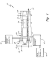
- FIG. 1 is a schematic side view of a gas turbine engine for use on an aircraft.
- FIG. 2 is a block diagram of an electrical power system for use with the gas turbine engine of FIG. 1 on the aircraft.
- FIG. 3 is a block diagram of an emergency power system used as part of the electrical power system of FIG. 2 .
- FIG. 1 is a schematic side view of gas turbine engine 10 for use on an aircraft (not shown).
- Gas turbine engine 10 includes compressor section 14, combustor section 16, and turbine section 18.
- Low pressure spool 20 (which includes low pressure compressor 22 and low pressure turbine 24 connected by low pressure shaft 26) and high pressure spool 28 (which includes high pressure compressor 30 and high pressure turbine 32 connected by high pressure shaft 34) each extend from compressor section 14 to turbine section 18.
- Propulsion fan 36 is connected to and driven by low pressure spool 20.
- a fan drive gear system 38 may be included between the propulsion fan 36 and low pressure spool 20.
- the general construction and operation of gas turbine engines is well-known in the art, and therefore detailed discussion here is unnecessary.
- Accessory gearbox 42 connects main motor-generator 44 to high pressure spool 28.
- Main motor-generator 44 can act as an electric motor to drive high pressure spool 28, and can also act as an electrical generator when driven by high pressure spool 28.
- high pressure spool 28 drives main motor-generator 44 to generate electrical energy.
- main motor-generator 44 can be connected to high pressure spool 28 without using accessory gearbox 42.
- Emergency motor-generator 48 is connected to low pressure spool 20.
- Emergency motor-generator 48 can act as an electric motor to drive low pressure spool 20, and can also act as an electrical generator when driven by low pressure spool 20.
- emergency motor-generator 48 can be connected to low pressure spool 20 through gearing (not shown).
- gearing not shown.
- gas turbine engine 10 fails to operate normally (for example, if combustion ceases)
- air forced over propulsion fan 36 can cause propulsion fan 36 to "windmill”.
- a windmilling propulsion fan 36 can drive low pressure spool 20, which drives emergency motor-generator 48 to generate electrical energy.
- FIG. 2 is a block diagram of electrical power system 50, which include main power system 52 and emergency power system 54.
- Main power system 52 includes multiple main power sources: gas turbine engine 10 connected to main motor-generator 44, gas turbine engine 10A connected to main motor-generator 44A (which are substantially similar to gas turbine engine 10 and main motor-generator 44, respectively), and auxiliary power unit (APU) 56 connected to APU motor-generator 58.
- APU 56 includes a gas turbine engine similar to gas turbine engine 10, but APU 56 does not provide propulsive thrust for the aircraft (not shown).
- main power system 52 can include more or fewer than three main power sources.
- main motor-generator 44, main motor-generator 44A, and APU motor-generator 58 are connected to AC (alternating current) main power bus 60 for supplying electrical energy to AC main electrical loads 62 and DC (direct current) main electrical loads 62A.
- AC main electrical loads 62 and DC main electrical loads 62A receive electrical power primarily or exclusively from some combination of gas turbine engine 10, gas turbine engine 10A, and/or APU 56.
- Emergency power system 54 includes multiple emergency power sources: emergency motor-generator 48 connected to low pressure spool 20 (shown in FIG. 1 ) of gas turbine engine 10, emergency motor-generator 48A connected to a low pressure spool (not shown) of gas turbine engine 10A, ram air turbine (RAT) 64 connected to RAT generator 66, flywheel 68 connected to flywheel motor-generator 70, battery 72, and fuel cell 74.
- RAT 64 is a turbine that can be deployed into an airstream exterior of the aircraft.
- Rotating RAT 64 causes RAT generator 66 to also rotate and, consequently, generate and supply electrical power to AC emergency power bus 76.
- Flywheel motor-generator 70 can convert mechanical energy stored in flywheel 68 to and from electrical energy stored on AC emergency power bus 76.
- Battery 72 and fuel cell 74 are connected to DC emergency power bus 76A for supplying electrical energy to DC emergency electrical loads 78A.
- Battery 72 stores electrical energy from DC emergency power bus 76A and returns electrical energy to DC emergency power bus 76A as needed.
- Fuel cell 74 can also supply electrical energy to DC emergency power bus 76A.
- AC emergency power bus 76 is connected to AC main power bus 60
- DC emergency electrical loads 78A are connected to AC main power bus 60 via AC/DC converter 79
- DC emergency electrical loads 78A are connected to AC emergency power bus 76 via AC/DC converter 79A.
- AC emergency electrical loads 78 can receive electrical power from AC main power bus 60 and/or DC emergency power bus 76A when such power is available.
- DC emergency electrical loads 78A can receive electrical power from AC main power bus 60 and/or AC emergency power bus 76 when such power is available.
- AC main electrical loads 62 and AC emergency electrical loads 78 can receive 115 volt three-phase AC power, 235 volt three-phase AC power, or another form of AC power.
- DC main electrical loads 62A and DC emergency electrical loads 78A can received 28 volt DC power, 270 volt DC power, or another form of DC power.
- Electrical power system 50 which include main power system 52 and emergency power system 54, is illustrated in a simplified form. In practice, additional electrical connections and/or components (not shown) can be added as needed for particular applications.
- AC emergency electrical loads 78 and DC emergency electrical loads 78A can still receive electrical power from some or all of emergency motor-generator 48, RAT generator 66, flywheel motor-generator 70, battery 72, and fuel cell 74.
- FIG. 3 is a block diagram of emergency power system 54.
- FIG. 3 illustrates portions of emergency power system 54 in greater detail than in FIG. 2 , but is still in a simplified form.
- emergency power system 54 as illustrated in FIG. 3 is simplified to a greater extent than as illustrated in FIG. 2 , because FIG. 3 illustrates only a single mechanical power source 80.
- emergency power system 54 is illustrated in FIG. 3 only as an example.
- additional electrical and hydraulic connections and/or components can be added as needed for particular applications.
- certain components illustrated in FIG. 3 can be omitted if not needed in a particular embodiment.
- Emergency power system 54 includes mechanical power source 80, which drives hydraulic pump 82, which drives emergency generator 84.
- Mechanical power source 80 can be any suitable source of mechanical power, such as propulsion fan 36 connected to low pressure spool 20 (shown in FIG. 1 ), RAT 64 (shown in FIG. 2 ), or flywheel 68 (shown in FIG. 2 ).
- Emergency generator 84 can be any suitable electrical generator, such as emergency motor-generator 48 (shown in FIGS. 1 and 2 ), RAT generator 66 (shown in FIG. 2 ), or flywheel motor-generator 70 (shown in FIG. 2 ).
- hydraulic pump 82 is mechanically connected between mechanical power source 80 and emergency generator 84 to rotate and transmit power there-between.
- Hydraulic pump 82 is also hydraulically connected to emergency hydraulic loads 86 via hydraulic power distribution network 87 to transmit hydraulic power thereto.
- Hydraulic accumulator 88 is connected between hydraulic pump 82 and hydraulic loads 86 and acts as a short term energy storage element.
- Emergency hydraulic loads 86 include one or more of the following: horizontal stabilizer 86A, vertical stabilizer 86B, flaps 86C, slats 86D, and ailerons 86E.
- Emergency hydraulic loads 86 can also include other hydraulic loads such as landing gear (not shown) and nose wheel steering equipment (not shown).
- mechanical power source 80 can provide hydraulic power to emergency hydraulic loads 86 when hydraulic power might otherwise be insufficient or not available.
- each emergency hydraulic load 86 can have two or more hydraulic inputs (not shown) to receive power from two or more hydraulic pumps 82.
- Such hydraulic pumps 82 are each connected to its respective mechanical power source 80.
- a given mechanical power source 80 can power multiple hydraulic pumps 82.
- hydraulic loads 86 can be powered electrically instead of hydraulically. In such embodiments, hydraulic pump 82 can be omitted.
- Emergency generator 84 is connected to DC emergency power bus 76A via AC/DC converter 79A.
- Electrical power distribution network 89 connects DC emergency power bus 76A to emergency electrical loads 90.
- Emergency electrical loads 90 include pilot display 90A, co-pilot display 90B, inertial navigation computer 90C, display control unit computer 90D, transponder 90E, backup transponder 90F, air data computer 90G, air speed data sensor 90H, air speed pitot tube heater 90I, and flight computer 90J.
- Emergency electrical loads 90 can also include other electrical loads such as landing gear (not shown) and nose wheel steering equipment (not shown).
- mechanical power source 80 can provide power to emergency electrical loads 90 when electrical power from main power system 52 is insufficient or not otherwise be available.
- Emergency electrical loads 90A-90J can be AC emergency electrical loads 78 (shown in FIG. 2 ), DC emergency electrical loads 78A (shown in FIG. 2 ) or some combination of both AC and DC. Accordingly some of emergency electrical loads 90A-90J may require separate power buses. Regardless of whether emergency electrical loads 90A-90J use DC or AC power, electrical power distribution network 89 can function substantially as described below.
- Electrical power distribution network 89 connects emergency generator 84 to emergency electrical loads 90.
- Electrical power distribution network 89 includes switches 91A-91J for selectively coupling and decoupling each respective emergency electrical load 90A-90J to and from emergency generator 84.
- Current sensor 92A senses current between emergency generator 84 and AC/DC converter 79A.
- Current sensor 92B senses current between DC emergency power bus 76A and all emergency electrical loads 90, collectively.
- Current sensor 92C senses current flowing to each emergency electrical load 90A-90J, individually.
- Current sensors 92A-92C are connected to and send current signals to controller 94.
- Aircraft sensors 96 are also connected to controller 94 for sending signals related to flight, engine, and other aircraft data.
- aircraft sensors 96 can be connected directly to controller 94, or can be connected to air data computer 90G, flight computer 90J, and/or another computer (not shown) which process raw data and then send data signals to controller 94.
- Aircraft sensors 96 include speed sensor 96A (which can be the same as or different than air speed data sensor 90H), altitude sensor 96B, attitude sensor 96C, GPS antenna 96D, high pressure shaft sensor 96E, low pressure shaft sensor 96F, and landing gear sensor 96G.
- Controller 94 determines emergency electrical power availability and emergency electrical power demand based on data from aircraft sensors 96 and current sensors 92A-92C.
- Emergency electrical power demand can include both present demand from emergency electrical loads 90 and anticipated demand from emergency electrical loads 90 over an anticipated duration of an emergency.
- Emergency electrical power availability can include both stored electrical power and electrical power anticipated to be generated over an anticipated duration of the emergency.
- controller 94 can determine present emergency electrical power availability and use that information to determine which emergency electrical loads 90 and emergency hydraulic loads 86 can be presently powered. Additionally, controller 94 can determine emergency electrical power availability over an anticipated duration of an emergency and use that information to determine which emergency electrical loads 90 and emergency hydraulic loads 86 can be powered for some or all of the emergency.
- controller 94 can consider a duration of an expected emergency and generate an expected energy production plan and an expected energy use plan. Available emergency electrical power can be determined from the expected energy production plan. The expected energy use plan is designed to work within the constraints of the available emergency electrical power.
- Controller 94 is connected to switches 91A-91J for selectively coupling and decoupling one or more emergency electrical load 90A-90J to and from DC emergency power bus 76A. Similarly, controller 94 can also be connected to valves 98A-98E for selectively coupling and decoupling emergency hydraulic loads 86A-86E to and from hydraulic power distribution network 87. In an alternative embodiment, valves 98A-98E can be connected to and controlled by a separate controller (not shown). Controller 94 can actuate switches 91A-91J and valves 98A-98E in accordance with the expected energy use plan.
- a priority rank can be assigned to each emergency electrical load 90 and also to each emergency hydraulic load 86.
- priority ranks could be assigned in load schedules as in Table 1 and Table 2: TABLE 1: emergency electrical loads 90: Priority Rank: Peak Power Draw (Watts): Emergency Power Draw (Watts): pilot display 90A 2 600 600 co-pilot display 90B 4 600 600 inertial navigation computer 90C 4 200 200 display control unit computer 90D 3 400 400 transponder 90E 2 1000 1000 backup transponder 90F 6 1000 0 air data computer 90G 2 250 250 air speed data sensor 90H 3 60 60 air speed pitot tube heater 90I 5 50 50 flight computer 90J 3 120 120 TABLE 2: Emergency Hydraulic Loads 86: Priority Rank: Peak Power Draw (Watts): Emergency Power Draw (Watts): horizontal stabilizer 86A 1 5000 1200 vertical stabilizer 86B 8 4000
- Tables 1 and 2 show each emergency electrical load 90 and emergency hydraulic load 86 with a numerical priority rank.
- a priority rank of one is the highest priority and a priority rank of ten is the lowest priority.
- Horizontal stabilizer 86A has a priority rank of one. This means that horizontal stabilizer 86A will always be powered if at all possible.
- ailerons 86E have a priority rank of nine. No emergency load has a priority rank of ten. This means that if any emergency electrical load 90 or emergency hydraulic load 86 must have its power cut, ailerons 86E will lose power first.
- Each priority rank represents a relative importance of each emergency electrical load 90 and emergency hydraulic load 86 during emergency operation.
- controller 94 can assign different priority ranks to each. For example, in Table 1 above, transponder 90E is assigned a relatively high priority rank of two, while backup transponder 90F is assigned a relatively low priority rank of six. If controller 94 determines that a particular emergency electrical load 90 has failed, controller 94 can assign it a reduced priority rank that is lower than its regular priority rank.
- Tables 1 and 2 also show the peak power draw for each emergency electrical load 90 and emergency hydraulic load 86, which is the highest rated power drawn during normal operation.
- Tables 1 and 2 further show emergency power draw for each emergency electrical load 90 and emergency hydraulic load 86 for a particular emergency situation.
- controller 94 determines that in a particular emergency situation, the expected energy production plan includes available emergency power of 5000 watts. Because 5000 watts is far less than the total peak power draw, controller 94 sets a priority rank threshold of five. Those emergency electrical loads 90 and emergency hydraulic loads 86 with a priority rank between one and five have a combined emergency power draw of 4880 watts. Thus, all emergency electrical loads 90 and emergency hydraulic loads 86 with a priority rank between one and five will receive power, and all emergency electrical loads 90 and emergency hydraulic loads 86 with a priority rank between six and ten will receive no power.
- controller 94 can ensure the most important emergency electrical loads 90 and emergency hydraulic loads 86 will receive power, even when there is not enough emergency power available to power all loads.
- controller 94 can set a priority rank threshold greater than or less than five.
- each emergency electrical load 90 and emergency hydraulic load 86 can have a priority rank, a peak power draw, and an emergency power draw different from those illustrated in Tables 1 and 2.
- Controller 94 can automatically decouple a lowest priority emergency electrical load 90 from emergency generator 84 either in anticipation of electrical power distribution network 89 demanding emergency power in excess of available emergency power or in anticipation of potential shutdown of emergency generator 84. If it is anticipated that electrical power distribution network 89 will continue to demand emergency power in excess of available emergency power even after decoupling the lowest priority emergency electrical load 90, then controller 94 can automatically decouple a next lowest priority electrical load 90 from emergency generator 84. For example, controller 94 can decouple one or more emergency electrical loads 90 in response to controller 94 determining that mechanical power source 80 is anticipated to stall absent the decoupling. Controller 94 can also automatically re-couple one or more emergency electrical loads 90 to emergency electrical generator 84 in response to an increase in the available emergency electrical power.
- Emergency electrical loads 90 are recoupled in order, based upon the priority rank assigned to each emergency electrical load 90. Actual current draw by each emergency electrical load 90 can often be substantially less than rated current draw. Consequently, controller 94 determines whether to couple or decouple each emergency electrical load 90 based upon actual current signals from current sensors 92A-92C as well as priority rank assigned to each emergency electrical load 90. Controller 94 can also consider data provided by aircraft sensors 96 in determining whether to couple or decouple a particular emergency electrical load 90.
- controller 94 can also automatically couple and decouple a lowest and/or next lowest priority emergency hydraulic load 86 from hydraulic pump 82 in anticipation of hydraulic power distribution network 87 demanding emergency power in excess of available emergency power.
- generator controller 100 has an energy extraction plan for operating emergency generator 84.
- generator controller 100 can control emergency motor-generator 48 to increase total energy extracted from low pressure spool 20 over an anticipated duration of an emergency, without loading low pressure spool 20 so much so as to cause it and propulsion fan 36 to stall. This can be done by predicting when low pressure spool 20 will have a relatively large amount of energy available for extraction and when it will have a relatively small amount of energy available for extraction.
- the energy extraction plan can be developed by controller 94, by generator controller 100, or by both.
- controller 94 and generator controller 100 are separate units that can communicate with one-another.
- controller 94 and generator controller 100 can be the same unit.
- one or more additional control units can be used to perform some of the functions described with respect to controller 94 and generator controller 100.
- the energy extraction plan can be developed based upon emergency electrical power demanded by emergency electrical loads 90 and emergency electrical power availability from emergency generator 84.
- Generator controller 100 then controls emergency generator 84 according to the energy extraction plan.
- Speed sensor 96A provides data on air speed of the aircraft.
- Altitude sensor 96B provides data on altitude of the aircraft.
- Attitude sensor 96C provides data on the current attitude or pitch of the aircraft.
- GPS antenna 96D provides actual position data for the aircraft, and consequently, distance from a suitable landing strip. All of this data can be used to determine how much power is likely to be generated by air flowing over propulsion fan 36 to drive and rotate low pressure spool 20 (and/or air flowing over RAT 64) in the immediate future and over the course of the entire emergency until a safe landing and a controlled stop has been completed.
- High shaft sensor 96E provides data on actual rotation speed of high pressure spool 28 (shown in FIG. 1 ), which is an indication of how much energy is stored in high pressure spool 28 for potential extraction by main motor-generator 44.
- Low shaft sensor 96F provides data on actual rotation speed of low pressure spool 20, which is an indication of how much energy is stored in low pressure spool 20 for potential extraction by emergency motor-generator 48.
- RAT 64 and flywheel 68 can also have shaft sensors (not shown) that function in a similar manner as high shaft sensor 96E and low shaft sensor 96F.
- Controller 94 and/or generator controller 100 can signal main motor-generator 44 to rotate high pressure spool 28 for storing energy. This can be done when battery 72 is fully charged and emergency electrical power is being generated in excess of emergency electrical power demand. Then when emergency electrical power generation is exceeded by demand, main motor-generator 44 can extract energy from high pressure spool 28 to recover previously stored energy. Thus, high pressure spool 28 can be used in a manner similar to that of flywheel 68.
- Landing gear sensor 96G provides data on the current position (deployed or retracted) of landing gear (not shown). If the landing gear is deployed, it can block air flow and create turbulence over RAT 64, if RAT 64 is positioned behind the landing gear. Thus, landing gear sensor 96G provides data that effectively indicates that power produced by RAT 64 can be expected to decrease.
- emergency power system 54 can provide power for the most important of emergency electrical loads 90 and emergency hydraulic loads 86, without stalling the mechanical power sources 80 on which the loads rely.
Landscapes
- Engineering & Computer Science (AREA)
- Chemical & Material Sciences (AREA)
- Combustion & Propulsion (AREA)
- Mechanical Engineering (AREA)
- General Engineering & Computer Science (AREA)
- Aviation & Aerospace Engineering (AREA)
- Stand-By Power Supply Arrangements (AREA)
Applications Claiming Priority (2)
| Application Number | Priority Date | Filing Date | Title |
|---|---|---|---|
| US13/036,968 US20130076120A1 (en) | 2011-02-28 | 2011-02-28 | Aircraft emergency power system |
| US13/036,994 US20120221157A1 (en) | 2011-02-28 | 2011-02-28 | Low pressure spool emergency generator |
Publications (3)
| Publication Number | Publication Date |
|---|---|
| EP2492451A2 true EP2492451A2 (fr) | 2012-08-29 |
| EP2492451A3 EP2492451A3 (fr) | 2016-04-06 |
| EP2492451B1 EP2492451B1 (fr) | 2021-05-19 |
Family
ID=45811291
Family Applications (1)
| Application Number | Title | Priority Date | Filing Date |
|---|---|---|---|
| EP12157402.4A Active EP2492451B1 (fr) | 2011-02-28 | 2012-02-28 | Aéronef avec générateur d'urgence couplé à un arbre basse pression |
Country Status (1)
| Country | Link |
|---|---|
| EP (1) | EP2492451B1 (fr) |
Cited By (7)
| Publication number | Priority date | Publication date | Assignee | Title |
|---|---|---|---|---|
| WO2014143218A1 (fr) * | 2013-03-13 | 2014-09-18 | Rolls-Royce North American Technologies, Inc. | Moteur à turbine à gaz et système électrique comprenant des bus électriques |
| WO2014158238A1 (fr) * | 2013-03-14 | 2014-10-02 | Rolls-Royce Corporation | Procédé et système de commande de propulsion intégrée intelligente |
| WO2016108878A1 (fr) * | 2014-12-31 | 2016-07-07 | Mra Systems, Inc. | Aéronef utilisant des systèmes de récupération d'énergie |
| EP2783986B1 (fr) * | 2013-03-28 | 2019-05-01 | Hamilton Sundstrand Corporation | Système de démarrage de pompe hydraulique et procédé |
| US20210122488A1 (en) * | 2019-10-23 | 2021-04-29 | Rolls-Royce Plc | Aircraft auxiliary power unit |
| EP2584175B1 (fr) | 2011-10-21 | 2021-05-05 | Raytheon Technologies Corporation | Moteur à turbine à gaz et son procédé de fonctionnement |
| CN116409468A (zh) * | 2022-01-10 | 2023-07-11 | 通用电气公司 | 用于飞行器的电源 |
Families Citing this family (1)
| Publication number | Priority date | Publication date | Assignee | Title |
|---|---|---|---|---|
| CN107264812B (zh) * | 2016-04-08 | 2019-10-18 | 陕西飞机工业(集团)有限公司 | 一种飞机应急多余度供电电路 |
Family Cites Families (6)
| Publication number | Priority date | Publication date | Assignee | Title |
|---|---|---|---|---|
| US3379893A (en) * | 1965-04-08 | 1968-04-23 | Navy Usa | Electrical bus monitoring system for aircraft |
| US4912921A (en) * | 1988-03-14 | 1990-04-03 | Sundstrand Corporation | Low speed spool emergency power extraction system |
| US6023134A (en) * | 1996-10-25 | 2000-02-08 | Daimlerchrysler Aerospace Airbus Gmbh | Power conversion system for bi-directional conversion between hydraulic power and electrical power |
| US20060174629A1 (en) * | 2004-08-24 | 2006-08-10 | Honeywell International, Inc | Method and system for coordinating engine operation with electrical power extraction in a more electric vehicle |
| US7841163B2 (en) * | 2006-11-13 | 2010-11-30 | Hamilton Sundstrand Corporation | Turbofan emergency generator |
| US8424800B2 (en) * | 2010-06-23 | 2013-04-23 | Hamilton Sundstrand Corporation | Multi-source emergency power optimization |
-
2012
- 2012-02-28 EP EP12157402.4A patent/EP2492451B1/fr active Active
Non-Patent Citations (1)
| Title |
|---|
| None |
Cited By (13)
| Publication number | Priority date | Publication date | Assignee | Title |
|---|---|---|---|---|
| EP2584175B1 (fr) | 2011-10-21 | 2021-05-05 | Raytheon Technologies Corporation | Moteur à turbine à gaz et son procédé de fonctionnement |
| US9601970B2 (en) | 2013-03-13 | 2017-03-21 | Rolls-Royce North American Technologies, Inc. | Gas turbine engine and electrical system |
| US10797628B2 (en) | 2013-03-13 | 2020-10-06 | Rolls-Royce North American Technologies, Inc. | Gas turbine engine and electrical system |
| WO2014143218A1 (fr) * | 2013-03-13 | 2014-09-18 | Rolls-Royce North American Technologies, Inc. | Moteur à turbine à gaz et système électrique comprenant des bus électriques |
| WO2014158238A1 (fr) * | 2013-03-14 | 2014-10-02 | Rolls-Royce Corporation | Procédé et système de commande de propulsion intégrée intelligente |
| US9156560B2 (en) | 2013-03-14 | 2015-10-13 | Rolls-Royce Corporation | Intelligent integrated propulsion control system and method |
| EP2783986B1 (fr) * | 2013-03-28 | 2019-05-01 | Hamilton Sundstrand Corporation | Système de démarrage de pompe hydraulique et procédé |
| JP2018500234A (ja) * | 2014-12-31 | 2018-01-11 | エムアールエイ・システムズ・エルエルシー | エネルギー回収システムを使用する航空機 |
| CN107108018A (zh) * | 2014-12-31 | 2017-08-29 | Mra系统有限公司 | 利用能量回收系统的飞行器 |
| WO2016108878A1 (fr) * | 2014-12-31 | 2016-07-07 | Mra Systems, Inc. | Aéronef utilisant des systèmes de récupération d'énergie |
| US20210122488A1 (en) * | 2019-10-23 | 2021-04-29 | Rolls-Royce Plc | Aircraft auxiliary power unit |
| US12017790B2 (en) * | 2019-10-23 | 2024-06-25 | Rolls-Royce Plc | Aircraft auxiliary power unit |
| CN116409468A (zh) * | 2022-01-10 | 2023-07-11 | 通用电气公司 | 用于飞行器的电源 |
Also Published As
| Publication number | Publication date |
|---|---|
| EP2492451A3 (fr) | 2016-04-06 |
| EP2492451B1 (fr) | 2021-05-19 |
Similar Documents
| Publication | Publication Date | Title |
|---|---|---|
| US20120221157A1 (en) | Low pressure spool emergency generator | |
| US20130076120A1 (en) | Aircraft emergency power system | |
| EP2492451B1 (fr) | Aéronef avec générateur d'urgence couplé à un arbre basse pression | |
| US11597504B2 (en) | Architecture for a propulsion system of a helicopter including a hybrid turboshaft engine and a system for reactivating said hybrid turboshaft engine | |
| US11548651B2 (en) | Asymmeiric hybrid aircraft idle | |
| GB2491982A (en) | Aircraft emergency power system incorporating a fuel cell | |
| JP6955421B2 (ja) | 航空機の制御システム、航空機の制御方法、航空機の制御プログラム及び航空機 | |
| US10301011B2 (en) | Electrified rotorcraft | |
| CN107878762B (zh) | 一种长航时无人机油电混合动力系统及控制方法 | |
| EP2468624B1 (fr) | Dispositif de propulsion maritime | |
| CN107074366B (zh) | 直升机 | |
| US20200277063A1 (en) | Normal mode operation of hybrid electric propulsion systems | |
| US20120025032A1 (en) | Electrical architecture for a rotary wing aircraft with a hybrid power plant | |
| EP2735507A1 (fr) | Installation motrice, application d'une telle installation motrice, et procédé mis en oeuvre par cette installation motrice | |
| EP3895993B1 (fr) | Schéma de charge pour systèmes de propulsion électrique | |
| US12166371B2 (en) | Battery charge difference calculation system | |
| EP4102044A2 (fr) | Distribution de la puissance d'un moteur électrique hybride | |
| US20250371982A1 (en) | Hybrid electric engine power distribution | |
| US11718408B2 (en) | Electric power system for powerplants of a multi-engine aircraft | |
| EP2407660A2 (fr) | Système de génération de puissance hydraulique auxiliaire | |
| US12291995B2 (en) | Hybrid electric single engine descent power extraction control | |
| US20230138513A1 (en) | Twin propulsor, parallel hybrid, streamlined nacelle propulsion system | |
| US20230139190A1 (en) | Hybrid electric single engine descent energy management | |
| US20050006954A1 (en) | Aircraft secondary electric load controlling system | |
| EP4450395B1 (fr) | Unité d'alimentation électrique de secours hybride |
Legal Events
| Date | Code | Title | Description |
|---|---|---|---|
| PUAI | Public reference made under article 153(3) epc to a published international application that has entered the european phase |
Free format text: ORIGINAL CODE: 0009012 |
|
| AK | Designated contracting states |
Kind code of ref document: A2 Designated state(s): AL AT BE BG CH CY CZ DE DK EE ES FI FR GB GR HR HU IE IS IT LI LT LU LV MC MK MT NL NO PL PT RO RS SE SI SK SM TR |
|
| AX | Request for extension of the european patent |
Extension state: BA ME |
|
| PUAL | Search report despatched |
Free format text: ORIGINAL CODE: 0009013 |
|
| AK | Designated contracting states |
Kind code of ref document: A3 Designated state(s): AL AT BE BG CH CY CZ DE DK EE ES FI FR GB GR HR HU IE IS IT LI LT LU LV MC MK MT NL NO PL PT RO RS SE SI SK SM TR |
|
| AX | Request for extension of the european patent |
Extension state: BA ME |
|
| RIC1 | Information provided on ipc code assigned before grant |
Ipc: F02C 7/36 20060101ALI20160226BHEP Ipc: F01D 15/10 20060101AFI20160226BHEP Ipc: F02C 7/32 20060101ALI20160226BHEP Ipc: B64D 41/00 20060101ALI20160226BHEP |
|
| 17P | Request for examination filed |
Effective date: 20161006 |
|
| RBV | Designated contracting states (corrected) |
Designated state(s): AL AT BE BG CH CY CZ DE DK EE ES FI FR GB GR HR HU IE IS IT LI LT LU LV MC MK MT NL NO PL PT RO RS SE SI SK SM TR |
|
| STAA | Information on the status of an ep patent application or granted ep patent |
Free format text: STATUS: EXAMINATION IS IN PROGRESS |
|
| 17Q | First examination report despatched |
Effective date: 20190708 |
|
| GRAP | Despatch of communication of intention to grant a patent |
Free format text: ORIGINAL CODE: EPIDOSNIGR1 |
|
| STAA | Information on the status of an ep patent application or granted ep patent |
Free format text: STATUS: GRANT OF PATENT IS INTENDED |
|
| INTG | Intention to grant announced |
Effective date: 20201201 |
|
| RIN1 | Information on inventor provided before grant (corrected) |
Inventor name: JACQUES, DAVID L. Inventor name: FINNEY, ADAM M. Inventor name: KRENZ, MICHAEL Inventor name: WAGNER, CARL A. |
|
| GRAS | Grant fee paid |
Free format text: ORIGINAL CODE: EPIDOSNIGR3 |
|
| GRAA | (expected) grant |
Free format text: ORIGINAL CODE: 0009210 |
|
| STAA | Information on the status of an ep patent application or granted ep patent |
Free format text: STATUS: THE PATENT HAS BEEN GRANTED |
|
| RAP3 | Party data changed (applicant data changed or rights of an application transferred) |
Owner name: HAMILTON SUNDSTRAND CORPORATION |
|
| AK | Designated contracting states |
Kind code of ref document: B1 Designated state(s): AL AT BE BG CH CY CZ DE DK EE ES FI FR GB GR HR HU IE IS IT LI LT LU LV MC MK MT NL NO PL PT RO RS SE SI SK SM TR |
|
| REG | Reference to a national code |
Ref country code: GB Ref legal event code: FG4D |
|
| RAP4 | Party data changed (patent owner data changed or rights of a patent transferred) |
Owner name: HAMILTON SUNDSTRAND CORPORATION |
|
| REG | Reference to a national code |
Ref country code: CH Ref legal event code: EP |
|
| REG | Reference to a national code |
Ref country code: DE Ref legal event code: R096 Ref document number: 602012075588 Country of ref document: DE |
|
| REG | Reference to a national code |
Ref country code: AT Ref legal event code: REF Ref document number: 1394148 Country of ref document: AT Kind code of ref document: T Effective date: 20210615 |
|
| REG | Reference to a national code |
Ref country code: IE Ref legal event code: FG4D |
|
| REG | Reference to a national code |
Ref country code: LT Ref legal event code: MG9D |
|
| REG | Reference to a national code |
Ref country code: AT Ref legal event code: MK05 Ref document number: 1394148 Country of ref document: AT Kind code of ref document: T Effective date: 20210519 |
|
| REG | Reference to a national code |
Ref country code: NL Ref legal event code: MP Effective date: 20210519 |
|
| PG25 | Lapsed in a contracting state [announced via postgrant information from national office to epo] |
Ref country code: FI Free format text: LAPSE BECAUSE OF FAILURE TO SUBMIT A TRANSLATION OF THE DESCRIPTION OR TO PAY THE FEE WITHIN THE PRESCRIBED TIME-LIMIT Effective date: 20210519 Ref country code: LT Free format text: LAPSE BECAUSE OF FAILURE TO SUBMIT A TRANSLATION OF THE DESCRIPTION OR TO PAY THE FEE WITHIN THE PRESCRIBED TIME-LIMIT Effective date: 20210519 Ref country code: HR Free format text: LAPSE BECAUSE OF FAILURE TO SUBMIT A TRANSLATION OF THE DESCRIPTION OR TO PAY THE FEE WITHIN THE PRESCRIBED TIME-LIMIT Effective date: 20210519 Ref country code: BG Free format text: LAPSE BECAUSE OF FAILURE TO SUBMIT A TRANSLATION OF THE DESCRIPTION OR TO PAY THE FEE WITHIN THE PRESCRIBED TIME-LIMIT Effective date: 20210819 Ref country code: AT Free format text: LAPSE BECAUSE OF FAILURE TO SUBMIT A TRANSLATION OF THE DESCRIPTION OR TO PAY THE FEE WITHIN THE PRESCRIBED TIME-LIMIT Effective date: 20210519 |
|
| PG25 | Lapsed in a contracting state [announced via postgrant information from national office to epo] |
Ref country code: IS Free format text: LAPSE BECAUSE OF FAILURE TO SUBMIT A TRANSLATION OF THE DESCRIPTION OR TO PAY THE FEE WITHIN THE PRESCRIBED TIME-LIMIT Effective date: 20210919 Ref country code: GR Free format text: LAPSE BECAUSE OF FAILURE TO SUBMIT A TRANSLATION OF THE DESCRIPTION OR TO PAY THE FEE WITHIN THE PRESCRIBED TIME-LIMIT Effective date: 20210820 Ref country code: LV Free format text: LAPSE BECAUSE OF FAILURE TO SUBMIT A TRANSLATION OF THE DESCRIPTION OR TO PAY THE FEE WITHIN THE PRESCRIBED TIME-LIMIT Effective date: 20210519 Ref country code: RS Free format text: LAPSE BECAUSE OF FAILURE TO SUBMIT A TRANSLATION OF THE DESCRIPTION OR TO PAY THE FEE WITHIN THE PRESCRIBED TIME-LIMIT Effective date: 20210519 Ref country code: SE Free format text: LAPSE BECAUSE OF FAILURE TO SUBMIT A TRANSLATION OF THE DESCRIPTION OR TO PAY THE FEE WITHIN THE PRESCRIBED TIME-LIMIT Effective date: 20210519 Ref country code: PT Free format text: LAPSE BECAUSE OF FAILURE TO SUBMIT A TRANSLATION OF THE DESCRIPTION OR TO PAY THE FEE WITHIN THE PRESCRIBED TIME-LIMIT Effective date: 20210920 Ref country code: PL Free format text: LAPSE BECAUSE OF FAILURE TO SUBMIT A TRANSLATION OF THE DESCRIPTION OR TO PAY THE FEE WITHIN THE PRESCRIBED TIME-LIMIT Effective date: 20210519 Ref country code: NO Free format text: LAPSE BECAUSE OF FAILURE TO SUBMIT A TRANSLATION OF THE DESCRIPTION OR TO PAY THE FEE WITHIN THE PRESCRIBED TIME-LIMIT Effective date: 20210819 Ref country code: ES Free format text: LAPSE BECAUSE OF FAILURE TO SUBMIT A TRANSLATION OF THE DESCRIPTION OR TO PAY THE FEE WITHIN THE PRESCRIBED TIME-LIMIT Effective date: 20210519 |
|
| PG25 | Lapsed in a contracting state [announced via postgrant information from national office to epo] |
Ref country code: NL Free format text: LAPSE BECAUSE OF FAILURE TO SUBMIT A TRANSLATION OF THE DESCRIPTION OR TO PAY THE FEE WITHIN THE PRESCRIBED TIME-LIMIT Effective date: 20210519 |
|
| PG25 | Lapsed in a contracting state [announced via postgrant information from national office to epo] |
Ref country code: RO Free format text: LAPSE BECAUSE OF FAILURE TO SUBMIT A TRANSLATION OF THE DESCRIPTION OR TO PAY THE FEE WITHIN THE PRESCRIBED TIME-LIMIT Effective date: 20210519 Ref country code: SM Free format text: LAPSE BECAUSE OF FAILURE TO SUBMIT A TRANSLATION OF THE DESCRIPTION OR TO PAY THE FEE WITHIN THE PRESCRIBED TIME-LIMIT Effective date: 20210519 Ref country code: SK Free format text: LAPSE BECAUSE OF FAILURE TO SUBMIT A TRANSLATION OF THE DESCRIPTION OR TO PAY THE FEE WITHIN THE PRESCRIBED TIME-LIMIT Effective date: 20210519 Ref country code: DK Free format text: LAPSE BECAUSE OF FAILURE TO SUBMIT A TRANSLATION OF THE DESCRIPTION OR TO PAY THE FEE WITHIN THE PRESCRIBED TIME-LIMIT Effective date: 20210519 Ref country code: CZ Free format text: LAPSE BECAUSE OF FAILURE TO SUBMIT A TRANSLATION OF THE DESCRIPTION OR TO PAY THE FEE WITHIN THE PRESCRIBED TIME-LIMIT Effective date: 20210519 Ref country code: EE Free format text: LAPSE BECAUSE OF FAILURE TO SUBMIT A TRANSLATION OF THE DESCRIPTION OR TO PAY THE FEE WITHIN THE PRESCRIBED TIME-LIMIT Effective date: 20210519 |
|
| REG | Reference to a national code |
Ref country code: DE Ref legal event code: R097 Ref document number: 602012075588 Country of ref document: DE |
|
| PLBE | No opposition filed within time limit |
Free format text: ORIGINAL CODE: 0009261 |
|
| STAA | Information on the status of an ep patent application or granted ep patent |
Free format text: STATUS: NO OPPOSITION FILED WITHIN TIME LIMIT |
|
| 26N | No opposition filed |
Effective date: 20220222 |
|
| PG25 | Lapsed in a contracting state [announced via postgrant information from national office to epo] |
Ref country code: IS Free format text: LAPSE BECAUSE OF FAILURE TO SUBMIT A TRANSLATION OF THE DESCRIPTION OR TO PAY THE FEE WITHIN THE PRESCRIBED TIME-LIMIT Effective date: 20210919 Ref country code: AL Free format text: LAPSE BECAUSE OF FAILURE TO SUBMIT A TRANSLATION OF THE DESCRIPTION OR TO PAY THE FEE WITHIN THE PRESCRIBED TIME-LIMIT Effective date: 20210519 |
|
| PG25 | Lapsed in a contracting state [announced via postgrant information from national office to epo] |
Ref country code: IT Free format text: LAPSE BECAUSE OF FAILURE TO SUBMIT A TRANSLATION OF THE DESCRIPTION OR TO PAY THE FEE WITHIN THE PRESCRIBED TIME-LIMIT Effective date: 20210519 |
|
| PG25 | Lapsed in a contracting state [announced via postgrant information from national office to epo] |
Ref country code: MC Free format text: LAPSE BECAUSE OF FAILURE TO SUBMIT A TRANSLATION OF THE DESCRIPTION OR TO PAY THE FEE WITHIN THE PRESCRIBED TIME-LIMIT Effective date: 20210519 |
|
| REG | Reference to a national code |
Ref country code: CH Ref legal event code: PL |
|
| REG | Reference to a national code |
Ref country code: BE Ref legal event code: MM Effective date: 20220228 |
|
| PG25 | Lapsed in a contracting state [announced via postgrant information from national office to epo] |
Ref country code: LU Free format text: LAPSE BECAUSE OF NON-PAYMENT OF DUE FEES Effective date: 20220228 |
|
| PG25 | Lapsed in a contracting state [announced via postgrant information from national office to epo] |
Ref country code: LI Free format text: LAPSE BECAUSE OF NON-PAYMENT OF DUE FEES Effective date: 20220228 Ref country code: IE Free format text: LAPSE BECAUSE OF NON-PAYMENT OF DUE FEES Effective date: 20220228 Ref country code: CH Free format text: LAPSE BECAUSE OF NON-PAYMENT OF DUE FEES Effective date: 20220228 |
|
| PG25 | Lapsed in a contracting state [announced via postgrant information from national office to epo] |
Ref country code: BE Free format text: LAPSE BECAUSE OF NON-PAYMENT OF DUE FEES Effective date: 20220228 |
|
| P01 | Opt-out of the competence of the unified patent court (upc) registered |
Effective date: 20230522 |
|
| PG25 | Lapsed in a contracting state [announced via postgrant information from national office to epo] |
Ref country code: HU Free format text: LAPSE BECAUSE OF FAILURE TO SUBMIT A TRANSLATION OF THE DESCRIPTION OR TO PAY THE FEE WITHIN THE PRESCRIBED TIME-LIMIT; INVALID AB INITIO Effective date: 20120228 |
|
| PG25 | Lapsed in a contracting state [announced via postgrant information from national office to epo] |
Ref country code: MK Free format text: LAPSE BECAUSE OF FAILURE TO SUBMIT A TRANSLATION OF THE DESCRIPTION OR TO PAY THE FEE WITHIN THE PRESCRIBED TIME-LIMIT Effective date: 20210519 Ref country code: CY Free format text: LAPSE BECAUSE OF FAILURE TO SUBMIT A TRANSLATION OF THE DESCRIPTION OR TO PAY THE FEE WITHIN THE PRESCRIBED TIME-LIMIT Effective date: 20210519 |
|
| PG25 | Lapsed in a contracting state [announced via postgrant information from national office to epo] |
Ref country code: TR Free format text: LAPSE BECAUSE OF FAILURE TO SUBMIT A TRANSLATION OF THE DESCRIPTION OR TO PAY THE FEE WITHIN THE PRESCRIBED TIME-LIMIT Effective date: 20210519 |
|
| PG25 | Lapsed in a contracting state [announced via postgrant information from national office to epo] |
Ref country code: MT Free format text: LAPSE BECAUSE OF FAILURE TO SUBMIT A TRANSLATION OF THE DESCRIPTION OR TO PAY THE FEE WITHIN THE PRESCRIBED TIME-LIMIT Effective date: 20210519 |
|
| PGFP | Annual fee paid to national office [announced via postgrant information from national office to epo] |
Ref country code: GB Payment date: 20260121 Year of fee payment: 15 |
|
| PGFP | Annual fee paid to national office [announced via postgrant information from national office to epo] |
Ref country code: DE Payment date: 20260121 Year of fee payment: 15 |
|
| PGFP | Annual fee paid to national office [announced via postgrant information from national office to epo] |
Ref country code: FR Payment date: 20260121 Year of fee payment: 15 |