EP2492450A2 - Verfahren zur Formung eines explosionsgeschweißten Mantelringsegments einer Gasturbine - Google Patents
Verfahren zur Formung eines explosionsgeschweißten Mantelringsegments einer Gasturbine Download PDFInfo
- Publication number
- EP2492450A2 EP2492450A2 EP12156097A EP12156097A EP2492450A2 EP 2492450 A2 EP2492450 A2 EP 2492450A2 EP 12156097 A EP12156097 A EP 12156097A EP 12156097 A EP12156097 A EP 12156097A EP 2492450 A2 EP2492450 A2 EP 2492450A2
- Authority
- EP
- European Patent Office
- Prior art keywords
- alloy
- gas turbine
- turbine shroud
- explosion
- welded
- Prior art date
- Legal status (The legal status is an assumption and is not a legal conclusion. Google has not performed a legal analysis and makes no representation as to the accuracy of the status listed.)
- Withdrawn
Links
- 238000000034 method Methods 0.000 title claims abstract description 21
- 229910045601 alloy Inorganic materials 0.000 claims abstract description 89
- 239000000956 alloy Substances 0.000 claims abstract description 89
- 238000004880 explosion Methods 0.000 claims abstract description 26
- 238000003466 welding Methods 0.000 claims abstract description 23
- 239000000463 material Substances 0.000 claims description 17
- 238000005474 detonation Methods 0.000 claims description 6
- 230000007423 decrease Effects 0.000 claims 2
- 239000007789 gas Substances 0.000 description 30
- 238000005253 cladding Methods 0.000 description 7
- 238000002485 combustion reaction Methods 0.000 description 5
- 239000002360 explosive Substances 0.000 description 3
- XEEYBQQBJWHFJM-UHFFFAOYSA-N Iron Chemical compound [Fe] XEEYBQQBJWHFJM-UHFFFAOYSA-N 0.000 description 2
- PXHVJJICTQNCMI-UHFFFAOYSA-N Nickel Chemical compound [Ni] PXHVJJICTQNCMI-UHFFFAOYSA-N 0.000 description 2
- 238000000576 coating method Methods 0.000 description 2
- 238000005260 corrosion Methods 0.000 description 2
- 230000007797 corrosion Effects 0.000 description 2
- 239000013078 crystal Substances 0.000 description 2
- 239000000446 fuel Substances 0.000 description 2
- 230000000977 initiatory effect Effects 0.000 description 2
- 238000004519 manufacturing process Methods 0.000 description 2
- 239000000203 mixture Substances 0.000 description 2
- 230000003647 oxidation Effects 0.000 description 2
- 238000007254 oxidation reaction Methods 0.000 description 2
- 229910001220 stainless steel Inorganic materials 0.000 description 2
- 229910000601 superalloy Inorganic materials 0.000 description 2
- 229910000838 Al alloy Inorganic materials 0.000 description 1
- 229910000975 Carbon steel Inorganic materials 0.000 description 1
- 229910000881 Cu alloy Inorganic materials 0.000 description 1
- 229910000617 Mangalloy Inorganic materials 0.000 description 1
- 229910001182 Mo alloy Inorganic materials 0.000 description 1
- 229910000990 Ni alloy Inorganic materials 0.000 description 1
- 229910000831 Steel Inorganic materials 0.000 description 1
- 229910001362 Ta alloys Inorganic materials 0.000 description 1
- 229910001069 Ti alloy Inorganic materials 0.000 description 1
- 229910001093 Zr alloy Inorganic materials 0.000 description 1
- 229910000963 austenitic stainless steel Inorganic materials 0.000 description 1
- 238000005219 brazing Methods 0.000 description 1
- 239000010962 carbon steel Substances 0.000 description 1
- 230000015556 catabolic process Effects 0.000 description 1
- VNTLIPZTSJSULJ-UHFFFAOYSA-N chromium molybdenum Chemical compound [Cr].[Mo] VNTLIPZTSJSULJ-UHFFFAOYSA-N 0.000 description 1
- 239000011248 coating agent Substances 0.000 description 1
- 239000010941 cobalt Substances 0.000 description 1
- 229910017052 cobalt Inorganic materials 0.000 description 1
- GUTLYIVDDKVIGB-UHFFFAOYSA-N cobalt atom Chemical compound [Co] GUTLYIVDDKVIGB-UHFFFAOYSA-N 0.000 description 1
- 238000001816 cooling Methods 0.000 description 1
- 238000006731 degradation reaction Methods 0.000 description 1
- 230000007613 environmental effect Effects 0.000 description 1
- 238000005242 forging Methods 0.000 description 1
- -1 forgings Substances 0.000 description 1
- 238000010438 heat treatment Methods 0.000 description 1
- 229910052742 iron Inorganic materials 0.000 description 1
- 238000003754 machining Methods 0.000 description 1
- 229910052751 metal Inorganic materials 0.000 description 1
- 239000002184 metal Substances 0.000 description 1
- 150000002739 metals Chemical class 0.000 description 1
- 238000012986 modification Methods 0.000 description 1
- 230000004048 modification Effects 0.000 description 1
- 229910052759 nickel Inorganic materials 0.000 description 1
- 239000007787 solid Substances 0.000 description 1
- 239000010935 stainless steel Substances 0.000 description 1
- 229910001256 stainless steel alloy Inorganic materials 0.000 description 1
- 239000010959 steel Substances 0.000 description 1
- 230000007704 transition Effects 0.000 description 1
Images
Classifications
-
- F—MECHANICAL ENGINEERING; LIGHTING; HEATING; WEAPONS; BLASTING
- F01—MACHINES OR ENGINES IN GENERAL; ENGINE PLANTS IN GENERAL; STEAM ENGINES
- F01D—NON-POSITIVE DISPLACEMENT MACHINES OR ENGINES, e.g. STEAM TURBINES
- F01D11/00—Preventing or minimising internal leakage of working-fluid, e.g. between stages
- F01D11/08—Preventing or minimising internal leakage of working-fluid, e.g. between stages for sealing space between rotor blade tips and stator
-
- B—PERFORMING OPERATIONS; TRANSPORTING
- B23—MACHINE TOOLS; METAL-WORKING NOT OTHERWISE PROVIDED FOR
- B23K—SOLDERING OR UNSOLDERING; WELDING; CLADDING OR PLATING BY SOLDERING OR WELDING; CUTTING BY APPLYING HEAT LOCALLY, e.g. FLAME CUTTING; WORKING BY LASER BEAM
- B23K20/00—Non-electric welding by applying impact or other pressure, with or without the application of heat, e.g. cladding or plating
- B23K20/06—Non-electric welding by applying impact or other pressure, with or without the application of heat, e.g. cladding or plating by means of high energy impulses, e.g. magnetic energy
- B23K20/08—Explosive welding
-
- B—PERFORMING OPERATIONS; TRANSPORTING
- B23—MACHINE TOOLS; METAL-WORKING NOT OTHERWISE PROVIDED FOR
- B23K—SOLDERING OR UNSOLDERING; WELDING; CLADDING OR PLATING BY SOLDERING OR WELDING; CUTTING BY APPLYING HEAT LOCALLY, e.g. FLAME CUTTING; WORKING BY LASER BEAM
- B23K2101/00—Articles made by soldering, welding or cutting
- B23K2101/001—Turbines
-
- B—PERFORMING OPERATIONS; TRANSPORTING
- B23—MACHINE TOOLS; METAL-WORKING NOT OTHERWISE PROVIDED FOR
- B23K—SOLDERING OR UNSOLDERING; WELDING; CLADDING OR PLATING BY SOLDERING OR WELDING; CUTTING BY APPLYING HEAT LOCALLY, e.g. FLAME CUTTING; WORKING BY LASER BEAM
- B23K2103/00—Materials to be soldered, welded or cut
- B23K2103/02—Iron or ferrous alloys
- B23K2103/04—Steel or steel alloys
- B23K2103/05—Stainless steel
-
- B—PERFORMING OPERATIONS; TRANSPORTING
- B23—MACHINE TOOLS; METAL-WORKING NOT OTHERWISE PROVIDED FOR
- B23K—SOLDERING OR UNSOLDERING; WELDING; CLADDING OR PLATING BY SOLDERING OR WELDING; CUTTING BY APPLYING HEAT LOCALLY, e.g. FLAME CUTTING; WORKING BY LASER BEAM
- B23K2103/00—Materials to be soldered, welded or cut
- B23K2103/08—Non-ferrous metals or alloys
- B23K2103/10—Aluminium or alloys thereof
-
- B—PERFORMING OPERATIONS; TRANSPORTING
- B23—MACHINE TOOLS; METAL-WORKING NOT OTHERWISE PROVIDED FOR
- B23K—SOLDERING OR UNSOLDERING; WELDING; CLADDING OR PLATING BY SOLDERING OR WELDING; CUTTING BY APPLYING HEAT LOCALLY, e.g. FLAME CUTTING; WORKING BY LASER BEAM
- B23K2103/00—Materials to be soldered, welded or cut
- B23K2103/08—Non-ferrous metals or alloys
- B23K2103/12—Copper or alloys thereof
-
- B—PERFORMING OPERATIONS; TRANSPORTING
- B23—MACHINE TOOLS; METAL-WORKING NOT OTHERWISE PROVIDED FOR
- B23K—SOLDERING OR UNSOLDERING; WELDING; CLADDING OR PLATING BY SOLDERING OR WELDING; CUTTING BY APPLYING HEAT LOCALLY, e.g. FLAME CUTTING; WORKING BY LASER BEAM
- B23K2103/00—Materials to be soldered, welded or cut
- B23K2103/08—Non-ferrous metals or alloys
- B23K2103/14—Titanium or alloys thereof
-
- B—PERFORMING OPERATIONS; TRANSPORTING
- B23—MACHINE TOOLS; METAL-WORKING NOT OTHERWISE PROVIDED FOR
- B23K—SOLDERING OR UNSOLDERING; WELDING; CLADDING OR PLATING BY SOLDERING OR WELDING; CUTTING BY APPLYING HEAT LOCALLY, e.g. FLAME CUTTING; WORKING BY LASER BEAM
- B23K2103/00—Materials to be soldered, welded or cut
- B23K2103/18—Dissimilar materials
- B23K2103/20—Ferrous alloys and aluminium or alloys thereof
-
- B—PERFORMING OPERATIONS; TRANSPORTING
- B23—MACHINE TOOLS; METAL-WORKING NOT OTHERWISE PROVIDED FOR
- B23K—SOLDERING OR UNSOLDERING; WELDING; CLADDING OR PLATING BY SOLDERING OR WELDING; CUTTING BY APPLYING HEAT LOCALLY, e.g. FLAME CUTTING; WORKING BY LASER BEAM
- B23K2103/00—Materials to be soldered, welded or cut
- B23K2103/18—Dissimilar materials
- B23K2103/22—Ferrous alloys and copper or alloys thereof
-
- B—PERFORMING OPERATIONS; TRANSPORTING
- B23—MACHINE TOOLS; METAL-WORKING NOT OTHERWISE PROVIDED FOR
- B23K—SOLDERING OR UNSOLDERING; WELDING; CLADDING OR PLATING BY SOLDERING OR WELDING; CUTTING BY APPLYING HEAT LOCALLY, e.g. FLAME CUTTING; WORKING BY LASER BEAM
- B23K2103/00—Materials to be soldered, welded or cut
- B23K2103/18—Dissimilar materials
- B23K2103/24—Ferrous alloys and titanium or alloys thereof
-
- B—PERFORMING OPERATIONS; TRANSPORTING
- B23—MACHINE TOOLS; METAL-WORKING NOT OTHERWISE PROVIDED FOR
- B23K—SOLDERING OR UNSOLDERING; WELDING; CLADDING OR PLATING BY SOLDERING OR WELDING; CUTTING BY APPLYING HEAT LOCALLY, e.g. FLAME CUTTING; WORKING BY LASER BEAM
- B23K2103/00—Materials to be soldered, welded or cut
- B23K2103/18—Dissimilar materials
- B23K2103/26—Alloys of Nickel and Cobalt and Chromium
-
- F—MECHANICAL ENGINEERING; LIGHTING; HEATING; WEAPONS; BLASTING
- F05—INDEXING SCHEMES RELATING TO ENGINES OR PUMPS IN VARIOUS SUBCLASSES OF CLASSES F01-F04
- F05D—INDEXING SCHEME FOR ASPECTS RELATING TO NON-POSITIVE-DISPLACEMENT MACHINES OR ENGINES, GAS-TURBINES OR JET-PROPULSION PLANTS
- F05D2230/00—Manufacture
- F05D2230/20—Manufacture essentially without removing material
- F05D2230/23—Manufacture essentially without removing material by permanently joining parts together
- F05D2230/232—Manufacture essentially without removing material by permanently joining parts together by welding
-
- F—MECHANICAL ENGINEERING; LIGHTING; HEATING; WEAPONS; BLASTING
- F05—INDEXING SCHEMES RELATING TO ENGINES OR PUMPS IN VARIOUS SUBCLASSES OF CLASSES F01-F04
- F05D—INDEXING SCHEME FOR ASPECTS RELATING TO NON-POSITIVE-DISPLACEMENT MACHINES OR ENGINES, GAS-TURBINES OR JET-PROPULSION PLANTS
- F05D2240/00—Components
- F05D2240/10—Stators
- F05D2240/11—Shroud seal segments
-
- Y—GENERAL TAGGING OF NEW TECHNOLOGICAL DEVELOPMENTS; GENERAL TAGGING OF CROSS-SECTIONAL TECHNOLOGIES SPANNING OVER SEVERAL SECTIONS OF THE IPC; TECHNICAL SUBJECTS COVERED BY FORMER USPC CROSS-REFERENCE ART COLLECTIONS [XRACs] AND DIGESTS
- Y10—TECHNICAL SUBJECTS COVERED BY FORMER USPC
- Y10T—TECHNICAL SUBJECTS COVERED BY FORMER US CLASSIFICATION
- Y10T29/00—Metal working
- Y10T29/49—Method of mechanical manufacture
- Y10T29/49316—Impeller making
- Y10T29/4932—Turbomachine making
- Y10T29/49321—Assembling individual fluid flow interacting members, e.g., blades, vanes, buckets, on rotary support member
Definitions
- the present invention is directed to manufactured components and processes of forming manufactured components. More specifically, the present invention relates to explosion-welded components and explosion welding processes.
- the operating temperature within a gas turbine is both thermally and chemically hostile.
- Significant advances in high temperature capabilities have been achieved through the development of iron, nickel, and cobalt-based superalloys and the use of environmental coatings capable of protecting superalloys from oxidation, hot corrosion, etc., but coating systems continue to be developed to improve the performance of the materials.
- Certain known alloys are used for components disposed along the flow path of these hot gases. Certain portions of these components must be able to withstand temperatures higher than other portions of these components. For example, certain portions may be resistant to temperatures for adiabatic heating (for example, 800° F - 1250° F) and other portions may be further resistant to hot gases heated by the combustion processes (for example, in excess of 3000° F). Components made entirely of alloys resistant to the highest temperature may be undesirable by being overly expensive or failing to include other properties desirable in other portions of the components. Alternatively, components made entirely of alloys resistant only to the temperature of the lower temperature portions may fail.
- gas turbine shrouds are manufactured from one or more rings or cylinders.
- manufacturing and tooling facilities are configured for manufacturing gas turbine shrouds from one or more rings or cylinders.
- Welding of multiple materials to form gas turbine shrouds may include techniques such as weld build-up, strip cladding, brazing, or solid state bonding. These techniques suffer from a drawback that they may be limited based upon properties of the materials (for example, crystal structures, compositions, or other suitable properties).
- Explosion welding is a bonding technique that generally includes welding planar materials by an explosive force and results in a microstructure differing from other weld techniques. Explosion welding permits metals to be bonded that are otherwise generally incompatible. However, explosion welding processes have been limited to simple shapes and geometries. Therefore, current explosion welding techniques have been unable to bond structures in gas turbine shrouds.
- a gas turbine shroud includes a first alloy explosion welded to a second alloy.
- the first alloy forms at least a portion of a hot gas path of the gas turbine shroud.
- a gas turbine shroud includes an expansion region and a first alloy explosion welded to a second alloy.
- the expansion region of the gas turbine shroud includes the first alloy.
- a process of forming an explosion-welded gas turbine shroud includes explosion welding a first alloy to a second alloy.
- the first alloy forms at least a portion of a hot gas path of the gas turbine shroud.
- an explosion-welded gas turbine shroud a non-planar explosion-welded component, and a process of forming a non-planar explosion-welded component.
- Embodiments of the present disclosure permit components to be used in thermally and chemically hostile environments, permit components to be resistant to oxidation and/or hot corrosion, permit the overall material cost of components to be reduced in comparison to single alloy components, permit different portions of components to have different properties (for example, heat resistant properties), permit non-planar components to have properties available through explosion welding, permit materials having otherwise incompatible properties to be bonded (for example, otherwise incompatible crystal structures and/or compositions), and combinations thereof.
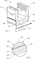
- FIG. 1 shows a non-planar explosion-welded component.
- FIG. 1 shows an explosion-welded gas turbine shroud 100.
- the shroud 100 is for use in a gas turbine and is capable of being arranged circumferentially and concentric with a rotor (not shown) on which turbine blades (not shown) are mounted.
- the shroud 100 includes ribs 107 extending from a substantially planar member 109.
- the ribs 107 and the substantially planar member 109 include the same material.
- the ribs 107 include material different from the substantially planar member 109.
- the shroud 100 includes a first alloy 102 and a second alloy 106.
- the first alloy 102 is positioned along the substantially planar member 109 as a cladding layer 104 and the second alloy 106 forms the substantially planar member 109 and is a backing layer 108.
- the cladding layer 104 is resistant to heat above a first temperature (for example, about 1000° F, about 1250° F, about 1500° F, about 2000° F, or about 3000° F).
- the backing layer 108 is resistant to heat above a second temperature (for example, between 800° F and 1250° F, about 800° F, about 1000° F, about 1250° F, about 1500° F, or about 2000° F).
- the first temperature is substantially higher than the second temperature.
- the second alloy 106 is unsuitable for being exposed to the first temperature.
- the first alloy 102 is an austenitic alloy, such as austenitic stainless steel or austenitic manganese steel.
- the first alloy 102 is any suitable cladding material. Suitable cladding materials include, but are not limited to, stainless steel alloys, aluminum alloys, tantalum alloys, nickel alloys, copper alloys, titanium alloys, zirconium alloys, and combinations thereof.
- the second alloy 106 is an austenitic alloy.
- the second alloy 106 is a ferritic alloy such as ferritic stainless steel.
- the second alloy 106 is any suitable backing material. Suitable backing materials include, but are not limited to, carbon steel, chromium-molybdenum alloy steel, forgings, stainless steel, or combinations thereof.
- explosion welding of the first alloy 102 to the second alloy 106 forms a microstructure having a gradient 203 between the first alloy 102 and the second alloy 106 as shown in enlarged region 200 corresponding to FIG. 1 .
- the first alloy 102 is austenitic and the second alloy 106 being ferritic
- the first alloy 102 includes a large grain region 202 distal from the second alloy 106 and a fine grain region 204 proximal to the second alloy 106.
- the second alloy 106 includes an amorphous region 206 proximal to the first alloy 102 and a high dislocation density region 208 distal from the first alloy 102.
- the explosion welding of the first alloy 102 to the second alloy 106 forms the gradient 203 with a transition region 210 between the first alloy 102 and the second alloy 106 thereby providing additional strength of the weld.
- the first alloy 102, the second alloy 106, and additional alloys (if present) are austenitic or ferritic based upon desired properties.
- the shroud 100 includes any other suitable features such as cooling passages, notches, chambers, mounting features, or other suitable features.
- hot gas flows along a path 101 abutting the cladding layer 104.
- the temperature of the gas within a first region 103 abutting the path 101 is higher than the temperature of the gas within an expansion region 105 abutting the path 101.
- the expansion region 105 is identifiable by including an angled, arced, or otherwise expanded region formed along the path 101 of the gas.
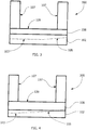
- FIGS. 3-4 show preforms 300 for forming the shroud 100.
- the preform 300 is formed by explosion welding the first alloy 102 to the second alloy 106.
- the preform 300 forms an embodiment of the shroud 100 with the first region 103 and the expansion region 105 including the first alloy 102.
- the preform 300 forms an embodiment of the shroud 100 with the expansion region 105 further including the second alloy 106.
- the forming of the shroud 100 or any other suitable component includes positioning a first portion of the shroud 100 and positioning a second portion of the shroud 100.
- the first portion includes the first alloy 102 (for example, the cladding layer 104) and the second portion includes the second alloy 106 (for example, the substantially planar member 109 or the backing layer 108).
- the first portion and the second portion are explosion welded together to form the preform 300.
- the preform 300 is then machined, deformed, further welded, or otherwise processed to remove excess material 302 and form the desired features of the shroud 100.
- the ribs 107 are formed on the preform 300 after the explosion welding by removing material through machining or by bonding the ribs 107 to the substantially planar member 109.
- the explosion welding of the first alloy 102 to the second alloy 106 is by ignition or initiation of detonation to direct the first alloy 102 with explosive force to contact the second alloy 106.
- the explosion welding is continued until a desired portion of the first alloy 102 is explosion welded to the second alloy 106.
- the explosion welding is performed along any suitable path. Suitable paths include, but are not limited to, a helical path for a cylindrical component (or preform), a series of paths, an S-shaped path, or combinations thereof.
- multiple coordinated ignitions or initiations of detonations coordinate the explosive welding (for example, concurrent, sequential, or otherwise controlled detonations).
- parameters include a predetermined pressure (for example, between about 1 GPa and about 10 GPa, about 5 GPa, or about 10 GPa), a predetermined detonation rate (for example, between about 1500 m/s and 4000 m/s, between about 1500 m/s and about 2000 m/s, between about 3500 m/s and about 4000 m/s, at about 1500 m/s, at about 2000 m/s, at about 3500 m/s, or at about 4000 m/s), a predetermined impact angle (for example, between about 3° and about 30°, between about 3° and about 5°, between about 25° and about 30°, at about 3°, at about 5°, at about 25°, or at about 30°), a predetermined collision velocity (for example, between about 225 m/s and about 550 m/s, between about 225 m/s and about 250 .
- a predetermined pressure for example, between about 1 GPa and about 10 GPa, about
Landscapes
- Engineering & Computer Science (AREA)
- Mechanical Engineering (AREA)
- General Engineering & Computer Science (AREA)
- Pressure Welding/Diffusion-Bonding (AREA)
- Arc Welding In General (AREA)
Applications Claiming Priority (1)
| Application Number | Priority Date | Filing Date | Title |
|---|---|---|---|
| US13/031,925 US20120213626A1 (en) | 2011-02-22 | 2011-02-22 | Explosion-welded gas turbine shroud and a process of forming an explosion-welded gas turbine |
Publications (2)
| Publication Number | Publication Date |
|---|---|
| EP2492450A2 true EP2492450A2 (de) | 2012-08-29 |
| EP2492450A3 EP2492450A3 (de) | 2014-12-03 |
Family
ID=45656127
Family Applications (1)
| Application Number | Title | Priority Date | Filing Date |
|---|---|---|---|
| EP12156097.3A Withdrawn EP2492450A3 (de) | 2011-02-22 | 2012-02-17 | Verfahren zur Formung eines explosionsgeschweißten Mantelringsegments einer Gasturbine |
Country Status (4)
| Country | Link |
|---|---|
| US (1) | US20120213626A1 (de) |
| EP (1) | EP2492450A3 (de) |
| JP (1) | JP2012172679A (de) |
| CN (1) | CN102650221A (de) |
Cited By (1)
| Publication number | Priority date | Publication date | Assignee | Title |
|---|---|---|---|---|
| EP3941675A1 (de) * | 2019-03-22 | 2022-01-26 | DMC Global Inc. | Plattierter artikel mit plattierungsschicht mit veränderlicher dicke |
Families Citing this family (1)
| Publication number | Priority date | Publication date | Assignee | Title |
|---|---|---|---|---|
| US20190055849A1 (en) * | 2015-11-10 | 2019-02-21 | Siemens Aktiengesellschaft | Laminated airfoil for a gas turbine |
Family Cites Families (11)
| Publication number | Priority date | Publication date | Assignee | Title |
|---|---|---|---|---|
| US4752184A (en) * | 1986-05-12 | 1988-06-21 | The United States Of America As Represented By The Secretary Of The Air Force | Self-locking outer air seal with full backside cooling |
| US5531369A (en) * | 1993-08-02 | 1996-07-02 | Electric Power Research Institute | Process for making machines resistant to cavitation and liquid droplet erosion |
| JPH07224358A (ja) * | 1994-02-14 | 1995-08-22 | Yamaki Kogyo Kk | スーパーステンレス鋼クラッドステンレス鋼板 |
| US5538393A (en) * | 1995-01-31 | 1996-07-23 | United Technologies Corporation | Turbine shroud segment with serpentine cooling channels having a bend passage |
| CA2254349C (en) * | 1997-11-19 | 2003-11-04 | Kabushiki Kaisha Toshiba | Joined structure of dissimilar metallic materials |
| US6554927B1 (en) * | 2000-11-24 | 2003-04-29 | Sigmabond Technologies Corporation | Method of explosive bonding, composition therefor and product thereof |
| US7300708B2 (en) * | 2004-03-16 | 2007-11-27 | General Electric Company | Erosion and wear resistant protective structures for turbine engine components |
| US7575418B2 (en) * | 2004-09-30 | 2009-08-18 | General Electric Company | Erosion and wear resistant protective structures for turbine components |
| US7832614B2 (en) * | 2007-05-11 | 2010-11-16 | Eaton Corporation | Method of explosion welding to create an explosion welded article having a non-planar shape |
| US20090053045A1 (en) * | 2007-08-22 | 2009-02-26 | General Electric Company | Turbine Shroud for Gas Turbine Assemblies and Processes for Forming the Shroud |
| EP2236237A1 (de) * | 2009-04-01 | 2010-10-06 | Siemens Aktiengesellschaft | Schweißanordnung zum explosionsschweissen eines Heissgasteils einer Turbine und Verfahren dafür |
-
2011
- 2011-02-22 US US13/031,925 patent/US20120213626A1/en not_active Abandoned
-
2012
- 2012-02-15 JP JP2012030029A patent/JP2012172679A/ja active Pending
- 2012-02-17 EP EP12156097.3A patent/EP2492450A3/de not_active Withdrawn
- 2012-02-22 CN CN2012100527839A patent/CN102650221A/zh active Pending
Non-Patent Citations (1)
| Title |
|---|
| None |
Cited By (2)
| Publication number | Priority date | Publication date | Assignee | Title |
|---|---|---|---|---|
| EP3941675A1 (de) * | 2019-03-22 | 2022-01-26 | DMC Global Inc. | Plattierter artikel mit plattierungsschicht mit veränderlicher dicke |
| EP3941675B1 (de) * | 2019-03-22 | 2025-08-27 | DMC Global Inc. | Plattierter artikel mit plattierungsschicht mit unterschiedlicher dicke und verfahren zur herstellung eines plattierten artikels |
Also Published As
| Publication number | Publication date |
|---|---|
| CN102650221A (zh) | 2012-08-29 |
| EP2492450A3 (de) | 2014-12-03 |
| JP2012172679A (ja) | 2012-09-10 |
| US20120213626A1 (en) | 2012-08-23 |
Similar Documents
| Publication | Publication Date | Title |
|---|---|---|
| EP2248997B1 (de) | System und Verfahren zur verbesserten Filmkühlung | |
| US8672613B2 (en) | Components with conformal curved film holes and methods of manufacture | |
| EP1526252B1 (de) | Herstellungsverfahren eines Turbinenrotors mit dreifachen Eigenschaften | |
| US20150083281A1 (en) | High temperature shape memory alloy actuators | |
| EP3421622B1 (de) | Festkörperschweissen von grobkörnigen pulvermetallurgischen superlegierungen auf nickelbasis | |
| EP2514550B1 (de) | Gasturbinenkomponente und Verfahren zum Schweißen der Komponente | |
| US20170198587A1 (en) | Cooled article | |
| EP2113634B1 (de) | Verfahren zur Reparatur eines Gasturbinenmotorgehäuses mit ausgetauschtem Flansch mittels Kaltmetallübertragung | |
| JP2011509845A (ja) | 熱伝導性構造 | |
| US20130078428A1 (en) | Components with ccoling channels and methods of manufacture | |
| US20180209280A1 (en) | Bladed disc and method of manufacturing the same | |
| US20100034661A1 (en) | Erosion resistant protective structure and process for applying same to a substrate | |
| EP3277859B1 (de) | Doppeltlegierte schaufel | |
| US20130078418A1 (en) | Components with cooling channels and methods of manufacture | |
| US10738648B2 (en) | Graphene discs and bores and methods of preparing the same | |
| US10767496B2 (en) | Turbine blade assembly with mounted platform | |
| EP2492450A2 (de) | Verfahren zur Formung eines explosionsgeschweißten Mantelringsegments einer Gasturbine | |
| US6901758B2 (en) | Method for repairing an air cooled combustor liner segment edge portion and repaired segment | |
| US10053987B2 (en) | Components with cooling channels and methods of manufacture | |
| EP2844423B1 (de) | Verfahren zur bearbeitung von schwebenden wandplatten einer brennkammer | |
| EP2882940A1 (de) | Komponente und verfahren zur kühlung einer komponente | |
| EP2236770B1 (de) | Gasturbinenbauteil mit kristalliner Mikrostruktur | |
| JP2015096709A (ja) | 耐熱合金部材およびこれを用いたガスタービン | |
| EP3198050B1 (de) | Verfahren zur selektiven entfernung von aluminiddiffusionsbeschichtungen | |
| EP2657453B1 (de) | Zwischenteil für eine gasturbine |
Legal Events
| Date | Code | Title | Description |
|---|---|---|---|
| PUAI | Public reference made under article 153(3) epc to a published international application that has entered the european phase |
Free format text: ORIGINAL CODE: 0009012 |
|
| AK | Designated contracting states |
Kind code of ref document: A2 Designated state(s): AL AT BE BG CH CY CZ DE DK EE ES FI FR GB GR HR HU IE IS IT LI LT LU LV MC MK MT NL NO PL PT RO RS SE SI SK SM TR |
|
| AX | Request for extension of the european patent |
Extension state: BA ME |
|
| PUAL | Search report despatched |
Free format text: ORIGINAL CODE: 0009013 |
|
| AK | Designated contracting states |
Kind code of ref document: A3 Designated state(s): AL AT BE BG CH CY CZ DE DK EE ES FI FR GB GR HR HU IE IS IT LI LT LU LV MC MK MT NL NO PL PT RO RS SE SI SK SM TR |
|
| AX | Request for extension of the european patent |
Extension state: BA ME |
|
| RIC1 | Information provided on ipc code assigned before grant |
Ipc: B23K 20/08 20060101ALI20141024BHEP Ipc: F01D 11/08 20060101AFI20141024BHEP |
|
| STAA | Information on the status of an ep patent application or granted ep patent |
Free format text: STATUS: THE APPLICATION IS DEEMED TO BE WITHDRAWN |
|
| 18D | Application deemed to be withdrawn |
Effective date: 20150604 |