EP2492447A1 - Refroidissement d'aubes de turbines - Google Patents
Refroidissement d'aubes de turbines Download PDFInfo
- Publication number
- EP2492447A1 EP2492447A1 EP11155472A EP11155472A EP2492447A1 EP 2492447 A1 EP2492447 A1 EP 2492447A1 EP 11155472 A EP11155472 A EP 11155472A EP 11155472 A EP11155472 A EP 11155472A EP 2492447 A1 EP2492447 A1 EP 2492447A1
- Authority
- EP
- European Patent Office
- Prior art keywords
- cooling
- cooling air
- ring
- openings
- blade
- Prior art date
- Legal status (The legal status is an assumption and is not a legal conclusion. Google has not performed a legal analysis and makes no representation as to the accuracy of the status listed.)
- Withdrawn
Links
- 238000001816 cooling Methods 0.000 title claims abstract description 52
- 238000005422 blasting Methods 0.000 claims 1
- 230000001419 dependent effect Effects 0.000 description 1
Images

Classifications
-
- F—MECHANICAL ENGINEERING; LIGHTING; HEATING; WEAPONS; BLASTING
- F01—MACHINES OR ENGINES IN GENERAL; ENGINE PLANTS IN GENERAL; STEAM ENGINES
- F01D—NON-POSITIVE DISPLACEMENT MACHINES OR ENGINES, e.g. STEAM TURBINES
- F01D11/00—Preventing or minimising internal leakage of working-fluid, e.g. between stages
- F01D11/02—Preventing or minimising internal leakage of working-fluid, e.g. between stages by non-contact sealings, e.g. of labyrinth type
-
- F—MECHANICAL ENGINEERING; LIGHTING; HEATING; WEAPONS; BLASTING
- F01—MACHINES OR ENGINES IN GENERAL; ENGINE PLANTS IN GENERAL; STEAM ENGINES
- F01D—NON-POSITIVE DISPLACEMENT MACHINES OR ENGINES, e.g. STEAM TURBINES
- F01D11/00—Preventing or minimising internal leakage of working-fluid, e.g. between stages
- F01D11/001—Preventing or minimising internal leakage of working-fluid, e.g. between stages for sealing space between stator blade and rotor
-
- F—MECHANICAL ENGINEERING; LIGHTING; HEATING; WEAPONS; BLASTING
- F01—MACHINES OR ENGINES IN GENERAL; ENGINE PLANTS IN GENERAL; STEAM ENGINES
- F01D—NON-POSITIVE DISPLACEMENT MACHINES OR ENGINES, e.g. STEAM TURBINES
- F01D5/00—Blades; Blade-carrying members; Heating, heat-insulating, cooling or antivibration means on the blades or the members
- F01D5/02—Blade-carrying members, e.g. rotors
- F01D5/08—Heating, heat-insulating or cooling means
- F01D5/081—Cooling fluid being directed on the side of the rotor disc or at the roots of the blades
- F01D5/082—Cooling fluid being directed on the side of the rotor disc or at the roots of the blades on the side of the rotor disc
-
- F—MECHANICAL ENGINEERING; LIGHTING; HEATING; WEAPONS; BLASTING
- F05—INDEXING SCHEMES RELATING TO ENGINES OR PUMPS IN VARIOUS SUBCLASSES OF CLASSES F01-F04
- F05D—INDEXING SCHEME FOR ASPECTS RELATING TO NON-POSITIVE-DISPLACEMENT MACHINES OR ENGINES, GAS-TURBINES OR JET-PROPULSION PLANTS
- F05D2260/00—Function
- F05D2260/20—Heat transfer, e.g. cooling
- F05D2260/201—Heat transfer, e.g. cooling by impingement of a fluid
-
- Y—GENERAL TAGGING OF NEW TECHNOLOGICAL DEVELOPMENTS; GENERAL TAGGING OF CROSS-SECTIONAL TECHNOLOGIES SPANNING OVER SEVERAL SECTIONS OF THE IPC; TECHNICAL SUBJECTS COVERED BY FORMER USPC CROSS-REFERENCE ART COLLECTIONS [XRACs] AND DIGESTS
- Y02—TECHNOLOGIES OR APPLICATIONS FOR MITIGATION OR ADAPTATION AGAINST CLIMATE CHANGE
- Y02T—CLIMATE CHANGE MITIGATION TECHNOLOGIES RELATED TO TRANSPORTATION
- Y02T50/00—Aeronautics or air transport
- Y02T50/60—Efficient propulsion technologies, e.g. for aircraft
Definitions
- the present invention relates to an apparatus for generating time-varying impact jets for cooling turbine rotor blades and turbine stator blades.
- By constructive design ensures that occur at intervals cooling air velocity packages or cooling air pulses for cooling in the stator or rotor blades.
- Blades, vanes, heat shields or other exposed to the hot gas flow of a gas turbine components must be intensively cooled in order to cope with the thermal and mechanical stresses occurring in the machine during operation.
- the rotor and stator blades of high pressure turbines in modern aircraft gas turbines are cooled by a system of cooling air passages within the blades. Cooling air is supplied to the cooling ducts, which is provided by the compressor (compressor). The cooling air hits within the blade, inter alia, as an impact jet (impingement cooling) on the inner blade surface. Compared to stationary impact rays, pulsed impact rays can significantly increase the cooling efficiency depending on the amplitude and the number of strokes.
- the invention consists of a constructive concept which makes it possible to generate at intervals cooling air speed packets or cooling air pulses for blade cooling. Instead of a steady impingement air flow, a change in the course of time air flow is generated.
- the invention is a device which is designed so that it comes through the rotation of the turbine rotor blades to a temporally fluctuating interruption or significant reduction of the impingement air flow.
- the device contains at least one opening through which the air flow, depending on the position of the turbine rotor blade, flows into it.
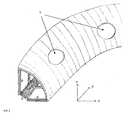
- the device For cooling of rotor blades, the device is mounted on a non-rotating part in Radierraum. On the inside of the device is cooling air. On the outside of the device rotates the rotor. Whenever the inlet opening rotating with the rotor blade is located in the cooling air channel of the rotor blade over an opening of the device, a significantly higher cooling air mass flow flows into the cooling air channel entrance of this blade for a short moment. In this way, at the outlet opening for the impact jets, ring vortex structures are detached which, depending on the amplitude and the number of strokes, increase the heat transfer on the surface acted on by the impact jet in the interior of the rotor blade.
- the device For cooling of stator blades, the device is mounted on a rotating part with the rotor in the Radierraum. On the inside of the device is cooling air. On the outside of the device, the inlet opening is located in the cooling air passage of the stator blade. Whenever the openings of the device rotating with the rotor are located above the inlet opening in the cooling air channel of a stator blade, a significantly higher cooling air mass flow flows into the cooling air channel inlet of this blade for a short moment. In this way, at the outlet opening for the impact jets, ring vortex structures are detached which, depending on the amplitude and the number of strokes, lead to an increase in the heat transfer on the surface acted upon by the impact jet in the interior of the stator blade.
- the cooling air velocity packets or cooling air pulses are passively generated. This device for generating the unsteady or pulsating impingement air streams can be installed in existing turbines.
- the device is attached to a non-rotating part in the wheel side space.
- the device is attached to a rotating part of the impeller in Radreteraum.
- the device is designed as a ring or ring section, which extends over part of the circumference or the entire circumference.
- this ring or ring section consists of a thin annular plate.
- the openings in the device are designed as bores. In another embodiment, the openings are designed as slots or long grooves or combinations of different opening shapes. In the preferred embodiment, the spaces between the openings are discretely spaced and the openings are made such that the entrance opening of the cooling air passage of each blade is at the same axial position as the opening in the device.
- At least one entrance opening of the cooling channel is sealed to the device (e.g., by a labyrinth seal).
Landscapes
- Engineering & Computer Science (AREA)
- Mechanical Engineering (AREA)
- General Engineering & Computer Science (AREA)
- Turbine Rotor Nozzle Sealing (AREA)
Priority Applications (1)
| Application Number | Priority Date | Filing Date | Title |
|---|---|---|---|
| EP11155472A EP2492447A1 (fr) | 2011-02-22 | 2011-02-22 | Refroidissement d'aubes de turbines |
Applications Claiming Priority (1)
| Application Number | Priority Date | Filing Date | Title |
|---|---|---|---|
| EP11155472A EP2492447A1 (fr) | 2011-02-22 | 2011-02-22 | Refroidissement d'aubes de turbines |
Publications (1)
| Publication Number | Publication Date |
|---|---|
| EP2492447A1 true EP2492447A1 (fr) | 2012-08-29 |
Family
ID=44144791
Family Applications (1)
| Application Number | Title | Priority Date | Filing Date |
|---|---|---|---|
| EP11155472A Withdrawn EP2492447A1 (fr) | 2011-02-22 | 2011-02-22 | Refroidissement d'aubes de turbines |
Country Status (1)
| Country | Link |
|---|---|
| EP (1) | EP2492447A1 (fr) |
Citations (4)
| Publication number | Priority date | Publication date | Assignee | Title |
|---|---|---|---|---|
| US3446482A (en) * | 1967-03-24 | 1969-05-27 | Gen Electric | Liquid cooled turbine rotor |
| GB2149022A (en) * | 1983-10-27 | 1985-06-05 | Rolls Royce | Warpable guide vanes for turbomachines |
| US4785624A (en) * | 1987-06-30 | 1988-11-22 | Teledyne Industries, Inc. | Turbine engine blade variable cooling means |
| EP1028230A1 (fr) * | 1999-02-09 | 2000-08-16 | ABB Alstom Power (Schweiz) AG | Pièce refroidie de turbine à gaz avec refroidissement ajustable |
-
2011
- 2011-02-22 EP EP11155472A patent/EP2492447A1/fr not_active Withdrawn
Patent Citations (4)
| Publication number | Priority date | Publication date | Assignee | Title |
|---|---|---|---|---|
| US3446482A (en) * | 1967-03-24 | 1969-05-27 | Gen Electric | Liquid cooled turbine rotor |
| GB2149022A (en) * | 1983-10-27 | 1985-06-05 | Rolls Royce | Warpable guide vanes for turbomachines |
| US4785624A (en) * | 1987-06-30 | 1988-11-22 | Teledyne Industries, Inc. | Turbine engine blade variable cooling means |
| EP1028230A1 (fr) * | 1999-02-09 | 2000-08-16 | ABB Alstom Power (Schweiz) AG | Pièce refroidie de turbine à gaz avec refroidissement ajustable |
Similar Documents
| Publication | Publication Date | Title |
|---|---|---|
| DE102009051651B4 (de) | Windkraftgenerator mit Innenkühlkreislauf | |
| EP1659293B1 (fr) | Turbomachine | |
| DE102009044585B4 (de) | Verfahren zum Betreiben eines Turbinentriebwerks und Anordnung in einem Turbinentriebwerk | |
| EP3101231B1 (fr) | Dispositif de refroidissement d'une paroi d'un composant d'une turbine à gaz | |
| JP6765973B2 (ja) | 磁気アキシャル軸受のための冷却システム | |
| US9341078B2 (en) | Blade for a turbo machine having labyrinth seal cooling passage | |
| EP2615244B1 (fr) | Aube de turbine refroidie par couche d'air comportant une pluralité de rainures à la surface extérieure | |
| US11156099B2 (en) | Turbine engine airfoil with a modified leading edge | |
| SE465227B (sv) | Fluidtaetningsarrangemang foer en turbomaskin samt saett att foerhindra stroemmande arbetsfluid fraan att undkomma fraan stroemningsbanan | |
| EP2659093B1 (fr) | Turbomachine | |
| EP3880967A1 (fr) | Ventilateur diagonal équipé d'un dispositif directeur de sortie | |
| DE4223496A1 (de) | Vorrichtung zum Reduzieren der kinetischen Energie von berstenden Teilen | |
| DE112015005131B4 (de) | Kühlstruktur für Turbine, und Gasturbine | |
| EP2492452A1 (fr) | Procédé de construction d'une turbomachine | |
| EP0544023B1 (fr) | Machine électrique refroidie par gaz | |
| DE102011055046A1 (de) | Mantelleckstromabdeckung | |
| US10738654B2 (en) | Lubricating-oil collection cap for turbomachine equipment | |
| EP2492447A1 (fr) | Refroidissement d'aubes de turbines | |
| KR20150055576A (ko) | 로터 냉각부 | |
| US20150056057A1 (en) | Alternating nozzles for radial inflow turbine | |
| CN207750484U (zh) | 轴承润滑结构 | |
| US10968771B2 (en) | Method and system for ice tolerant bleed takeoff | |
| US10533449B2 (en) | Containment for a continuous flow machine | |
| EP3828382B1 (fr) | Rangée d'aubes de turbine à gaz à sortie acoustique réduite | |
| DE653514C (de) | Turbine |
Legal Events
| Date | Code | Title | Description |
|---|---|---|---|
| PUAI | Public reference made under article 153(3) epc to a published international application that has entered the european phase |
Free format text: ORIGINAL CODE: 0009012 |
|
| AK | Designated contracting states |
Kind code of ref document: A1 Designated state(s): AL AT BE BG CH CY CZ DE DK EE ES FI FR GB GR HR HU IE IS IT LI LT LU LV MC MK MT NL NO PL PT RO RS SE SI SK SM TR |
|
| AX | Request for extension of the european patent |
Extension state: BA ME |
|
| STAA | Information on the status of an ep patent application or granted ep patent |
Free format text: STATUS: THE APPLICATION IS DEEMED TO BE WITHDRAWN |
|
| 18D | Application deemed to be withdrawn |
Effective date: 20130301 |