EP2492442A2 - Turbine vane with impingement insert - Google Patents
Turbine vane with impingement insert Download PDFInfo
- Publication number
- EP2492442A2 EP2492442A2 EP12156802A EP12156802A EP2492442A2 EP 2492442 A2 EP2492442 A2 EP 2492442A2 EP 12156802 A EP12156802 A EP 12156802A EP 12156802 A EP12156802 A EP 12156802A EP 2492442 A2 EP2492442 A2 EP 2492442A2
- Authority
- EP
- European Patent Office
- Prior art keywords
- tube
- tube portions
- aerofoil portion
- expansion member
- vane
- Prior art date
- Legal status (The legal status is an assumption and is not a legal conclusion. Google has not performed a legal analysis and makes no representation as to the accuracy of the status listed.)
- Granted
Links
- 239000007789 gas Substances 0.000 claims abstract description 14
- 238000001816 cooling Methods 0.000 claims abstract description 11
- 238000004519 manufacturing process Methods 0.000 claims abstract description 3
- 230000015572 biosynthetic process Effects 0.000 claims description 10
- 230000006835 compression Effects 0.000 claims description 10
- 238000007906 compression Methods 0.000 claims description 10
- 238000005755 formation reaction Methods 0.000 claims description 10
- 238000003780 insertion Methods 0.000 claims description 8
- 230000037431 insertion Effects 0.000 claims description 8
- 238000007789 sealing Methods 0.000 description 10
- 238000002485 combustion reaction Methods 0.000 description 3
- 230000001141 propulsive effect Effects 0.000 description 3
- 230000008602 contraction Effects 0.000 description 2
- 230000001595 contractor effect Effects 0.000 description 1
- 239000012530 fluid Substances 0.000 description 1
- 239000000446 fuel Substances 0.000 description 1
- 239000000203 mixture Substances 0.000 description 1
- 238000012986 modification Methods 0.000 description 1
- 230000004048 modification Effects 0.000 description 1
- 239000010705 motor oil Substances 0.000 description 1
- 238000003825 pressing Methods 0.000 description 1
- 230000003068 static effect Effects 0.000 description 1
- 238000003466 welding Methods 0.000 description 1
Images


Classifications
-
- F—MECHANICAL ENGINEERING; LIGHTING; HEATING; WEAPONS; BLASTING
- F01—MACHINES OR ENGINES IN GENERAL; ENGINE PLANTS IN GENERAL; STEAM ENGINES
- F01D—NON-POSITIVE DISPLACEMENT MACHINES OR ENGINES, e.g. STEAM TURBINES
- F01D5/00—Blades; Blade-carrying members; Heating, heat-insulating, cooling or antivibration means on the blades or the members
- F01D5/12—Blades
- F01D5/14—Form or construction
- F01D5/18—Hollow blades, i.e. blades with cooling or heating channels or cavities; Heating, heat-insulating or cooling means on blades
- F01D5/187—Convection cooling
- F01D5/188—Convection cooling with an insert in the blade cavity to guide the cooling fluid, e.g. forming a separation wall
- F01D5/189—Convection cooling with an insert in the blade cavity to guide the cooling fluid, e.g. forming a separation wall the insert having a tubular cross-section, e.g. airfoil shape
-
- F—MECHANICAL ENGINEERING; LIGHTING; HEATING; WEAPONS; BLASTING
- F05—INDEXING SCHEMES RELATING TO ENGINES OR PUMPS IN VARIOUS SUBCLASSES OF CLASSES F01-F04
- F05D—INDEXING SCHEME FOR ASPECTS RELATING TO NON-POSITIVE-DISPLACEMENT MACHINES OR ENGINES, GAS-TURBINES OR JET-PROPULSION PLANTS
- F05D2240/00—Components
- F05D2240/10—Stators
- F05D2240/12—Fluid guiding means, e.g. vanes
- F05D2240/122—Fluid guiding means, e.g. vanes related to the trailing edge of a stator vane
-
- F—MECHANICAL ENGINEERING; LIGHTING; HEATING; WEAPONS; BLASTING
- F05—INDEXING SCHEMES RELATING TO ENGINES OR PUMPS IN VARIOUS SUBCLASSES OF CLASSES F01-F04
- F05D—INDEXING SCHEME FOR ASPECTS RELATING TO NON-POSITIVE-DISPLACEMENT MACHINES OR ENGINES, GAS-TURBINES OR JET-PROPULSION PLANTS
- F05D2240/00—Components
- F05D2240/55—Seals
-
- F—MECHANICAL ENGINEERING; LIGHTING; HEATING; WEAPONS; BLASTING
- F05—INDEXING SCHEMES RELATING TO ENGINES OR PUMPS IN VARIOUS SUBCLASSES OF CLASSES F01-F04
- F05D—INDEXING SCHEME FOR ASPECTS RELATING TO NON-POSITIVE-DISPLACEMENT MACHINES OR ENGINES, GAS-TURBINES OR JET-PROPULSION PLANTS
- F05D2260/00—Function
- F05D2260/20—Heat transfer, e.g. cooling
- F05D2260/201—Heat transfer, e.g. cooling by impingement of a fluid
-
- F—MECHANICAL ENGINEERING; LIGHTING; HEATING; WEAPONS; BLASTING
- F05—INDEXING SCHEMES RELATING TO ENGINES OR PUMPS IN VARIOUS SUBCLASSES OF CLASSES F01-F04
- F05D—INDEXING SCHEME FOR ASPECTS RELATING TO NON-POSITIVE-DISPLACEMENT MACHINES OR ENGINES, GAS-TURBINES OR JET-PROPULSION PLANTS
- F05D2260/00—Function
- F05D2260/30—Retaining components in desired mutual position
Definitions
- the present invention relates to a vane for directing hot gases in a gas turbine engine.
- a ducted fan gas turbine engine generally indicated at 10 has a principal and rotational axis X-X.
- the engine comprises, in axial flow series, an air intake 11, a propulsive fan 12, an intermediate pressure compressor 13, a high-pressure compressor 14, combustion equipment 15, a high-pressure turbine 16, and intermediate pressure turbine 17, a low-pressure turbine 18 and a core engine exhaust nozzle 19.
- a nacelle 21 generally surrounds the engine 10 and defines the intake 11, a bypass duct 22 and a bypass exhaust nozzle 23.
- the gas turbine engine 10 works in a conventional manner so that air entering the intake 11 is accelerated by the fan 12 to produce two air flows: a first air flow A into the intermediate pressure compressor 14 and a second air flow B which passes through the bypass duct 22 to provide propulsive thrust.
- the intermediate pressure compressor 13 compresses the air flow A directed into it before delivering that air to the high pressure compressor 14 where further compression takes place.
- the compressed air exhausted from the high-pressure compressor 14 is directed into the combustion equipment 15 where it is mixed with fuel and the mixture combusted.
- the resultant hot combustion products then expand through, and thereby drive the high, intermediate and low-pressure turbines 16, 17, 18 before being exhausted through the nozzle 19 to provide additional propulsive thrust.
- the high, intermediate and low-pressure turbines respectively drive the high and intermediate pressure compressors 14, 13 and the fan 12 by suitable interconnecting shafts.
- a row of static nozzle guide vanes (NGVs) mounted into the turbine casing is provided at the entrance to each of the high, intermediate and low-pressure turbines 16, 17, 18.
- the NGVs are shaped to swirl the gasflow in the direction of rotation of the following rotor blades, and thereby to convert part of the gasflow's heat and pressure energy into kinetic energy from which the rotor blades can generate power.
- the NGVs of particularly the high and intermediate-pressure turbines 16, 17 tend to be cooled in order to withstand the high temperatures to which they are exposed.
- Impingement cooling is typically used to cool intermediate-pressure NGVs.
- a conventional impingement tube 26 is inserted into the hollow NGV, as shown in Figure 2 , which is a schematic cross-section through an intermediate-pressure NGV 25, the cross-section containing the leading 27 and trailing 28 edges of the NGV.
- the tapered shape of the internal cavity of the NGV allows the tube to be inserted along an approximately radial direction R of the engine.
- the tube is shown in both its pre-inserted and fully inserted positions. Once inserted, the tube is fixed at both ends, e.g. by welding at one end and swaging at the other.
- the swaged end of the NGV can be configured to allow relative radial movement between that end and the casing so that differential thermal expansion/contraction effects can be accommodated.
- Ribs on the inner surface of the NGV walls space the tube from therefrom. Apertures are formed in the tube, predominantly in the leading edge region, but also optionally along the pressure and suction sides of the NGV. Cooling air enters the tube from either or both of its ends, forms jets as it passes through the apertures, and then impinges on the walls of the NGV to penetrate the surface boundary layer and provide effective cooling. The air then flows away in the space between the walls of the NGV and the tube, to exit the NGV at holes or a slot formed along its trailing edge.
- An impingement cooling scheme of this type can provide effective cooling, while also leaving the internal space of the impingement tube 26 free to carry e.g. support struts for supporting engine bearing structures, and engine oil and air feeds.
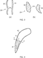
- Figure 3 shows schematically (a) a cross-section through another intermediate-pressure NGV 29, the cross-section being transversely across the engine and intersecting the suction 30 and pressure 31 sides of the NGV, and (b) a different cross-section containing the leading 32 and trailing 33 edges of the same NGV.
- the cross-sections show the NGV to have a re-entrant internal cavity feature 34 that would prevent insertion of a conventional impingement tube in the manner described above.
- An aim of the present invention is to provide a vane including an impingement tube which can inserted into the vane even when the vane has a re-entrant internal cavity feature.
- a first aspect of the present invention provides a vane for directing hot gases in a gas turbine engine, the vane including:
- each tube portion be configured such that it is possible to be positioned in the cavity of the aerofoil portion, even when that cavity has a re-entrant feature.
- the expansion member then holds the tube portions in position.
- the vane may have any one or, to the extent that they are compatible, any combination of the following optional features.
- one of the tube portions is positioned forward in the aerofoil portion and the other tube portion is positioned rearward in the aerofoil portion.
- the forward portion can wrap around the inside of the leading edge of the aerofoil portion
- the rearward portion can wrap around the inside of the trailing edge.
- Either or both of the tube portions may be resiliently deformable to facilitate its insertion into the aerofoil portion.
- the or each tube portions can be pinched inwardly to reduce its width on insertion into the aerofoil portion, and then allowed to resile outwardly to regain its shape after insertion.
- the expansion member urges the tube portions outwardly against the pressure surface side and the suction surface side of the aerofoil portion.
- the aerofoil portion typically has a plurality of projections and/or ridges on the internal surface against which the tube portions are held, the projections and/or ridges setting up a space between the impingement tube and the aerofoil portion through which the air from the cooling jets can flow.
- the outward urging can be achieved in various ways.
- One option is for expansion member to be slidably insertable into the aerofoil portion to urge the positioned tube portions outwardly with a wedging action.
- Another option is for expansion member to be rotatably connected to one of the tube portions to urge the positioned tube portions outwardly with a camming action.
- the expansion member and the tube portions have complimentary engaging formations which retain the expansion member in its location to urge the tube portions outwardly. In this way, inadvertent loss of the expansion member from the aerofoil portion, and hence loosening of the tube portions can be avoided.
- the expansion member is removably locatable in the aerofoil portion. This allows the tube portions also to be removably positionable so that they can be replaced if necessary.
- the tube portions may have seal formations at which the tube portions sealingly join to each other. Such formations help to prevent cooling air leaking through the joins between the tube portions and by-passing the jet-forming apertures.
- the expansion member can conveniently urge the tube portions outwardly at the seal formations. In this way, outward pressure from the expansion member can help to perfect the seals made by the seal formations.
- the expansion member may be a bimetallic strip. This can help the member to expand and contract with expansion and contraction of the aerofoil portion, maintaining the outward urging on the tube portions.
- the expansion member may be a compression spring which presses on the tube portions to urge them outwardly.
- the impingement tube typically includes more than two tube portions which are separately insertable into position in the aerofoil portion to form the covering, and a plurality of expansion members which, when the tube portions are in position in the aerofoil portion, are locatable in the aerofoil portion to urge each tube portion outwardly and thereby holds the tube portions in position against the aerofoil portion.
- the vane is a nozzle guide vane, e.g. an intermediate turbine nozzle guide vane.
- the vane has a re-entrant internal cavity feature which would prevent a one-piece impingement tube from being inserted therein.
- a second aspect of the present invention provides an impingement tube suitable for use in the vane of any one of the first aspect.
- Figures 4 to 6 show an aerofoil section through the aerofoil portion 40 of an NGV and successive steps in the fitting of an impingement tube therein.
- the aerofoil portion has a re-entrant internal cavity feature which prevents a one-piece impingement tube from being inserted therein. Instead, therefore, an impingement tube formed from two tube portions is fitted.
- the rearward tube portion 41 is inserted into the cavity of the aerofoil portion.
- the tube portion is V-shaped on the chordal section and can be resiliently deformed under inward compression to pinch the V (indicated by arrows A), thereby facilitating passage of the tube portion into the cavity.
- the tube portion is then slid (indicated by arrow B) rearwardly into position, the inward compression released, and the tube portion resiles outwardly to fit against gap-forming ridges and/or projections (not shown) formed on the inner surface of the rear part of the aerofoil portion.
- the forward tube portion 42 is inserted into the cavity.
- This tube portion is U-shaped on the chordal section and can also be resiliently deformed under inward compression to pinch the U (indicated by arrows C), again facilitating passage of the tube portion into the cavity.
- the tube portion is then slid (indicated by arrow D) forwardly into position, the inward compression released, and the tube portion resiles outwardly to fit against gap-forming ridges and/or projections (not shown) formed on the inner surface of the forward part of the aerofoil portion 40.
- an expansion member 43 is located in the aerofoil portion and urges each tube portion outwardly against facing parts of the pressure and suction side walls of the aerofoil portion.
- Sealing strips 44 which extend along the joins between the rearward 41 and forward 42 tube portions prevent cooling air leakage through joins, the seals being perfected by outward pressure exerted on them by the expansion member.
- the sealing strips may be fitted at the same time as the expansion member, or they may be integral or previously attached (e.g. brazed or welded on) parts of the tube portions
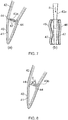
- Figure 7(a) and (b) shows schematically a possible form for the expansion member 43a, Figure 7(a) being the rearward part of an aerofoil section of the aerofoil portion 40, and Figure 7(b) being a cross-section transversely across the engine and intersecting the expansion member and the suction 45 and pressure 46 sides of the aerofoil portion.
- the expansion member is slidably inserted into the aerofoil portion along an approximately radial direction R of the engine.
- the member tapers from one end to the other so that it urges both tube portions outwardly at the sealing strips 44 against the aerofoil portion with a wedging action.
- Guide members 47 projecting inwardly from the sealing strips keep the expansion member aligned with the sealing strips as it is inserted.
- the expansion member can be brazed or welded to the tube portions or the NGV.
- complimentary mechanical engaging formations can be formed on the expansion member and the tube portions or the NGV which retain the member in place and preferably allow the member and (subsequently the tube portions) to be removed from the aerofoil portion.
- Figure 8 shows schematically the rearward part of an aerofoil section of the aerofoil portion 40 and another possible form for the expansion member 43b.
- the expansion member is rotatably connected along one edge to one of the sealing strips 44. After insertion of the tube portions 41, 42, the member is rotated, as indicated by the arrow E, so that its opposite edge engages with the opposite sealing strip and urges both tube portions outwardly against the aerofoil portion with a camming action.
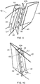
- Figure 9 shows a detailed exploded perspective view of the assembly of the rotatable expansion member 43b and the rearward part of the impingement tube (without the aerofoil portion 40)
- Figure 10 shows a detailed perspective view of the rotatable expansion member 43 and the rearward part of the impingement tube (again without the aerofoil portion) with the member rotated into location.
- Tangs 48 along the one side of the member fit into corresponding recesses 49 in one of the sealing strips 44 and allow the member to rotate about that the strip at that side.
- Tangs 50 along the other side of the member then fit into receiving slots 51 on the other sealing strip after the rotation of the member.
- the tangs, recess and slots provide complimentary engaging formations which retain the member in its location to urge the tube portions outwardly.
- Figure 11(a) and (b) shows schematically the rearward part of an aerofoil section of the aerofoil portion 40 and another possible form for the expansion member 43c.
- the member when initially located between the sealing strips 44 has a C-shaped cross-section, as shown in Figure 11 (a) .
- the member is then deformed (as indicated by arrow F) into a W-shaped cross-section, as shown in Figure 11 (b) .
- the member thus acts as compression spring which presses on the tube portions 41, 42 to urge them outwardly.
- Figure 12 shows schematically the rearward part of an aerofoil section of the aerofoil portion 40 and another possible form for the expansion member 43d.
- the member has a C-shaped cross-section and acts as compression spring pressing on the tube portions 41, 42 to urge them outwardly.
- the member is formed from a bimetallic strip which is configured to expand and contract with expansion and contraction of the aerofoil portion. In this way, the outward urging on the tube portions 41, 42 by the member can be maintained at different temperatures.
Landscapes
- Engineering & Computer Science (AREA)
- Mechanical Engineering (AREA)
- General Engineering & Computer Science (AREA)
- Turbine Rotor Nozzle Sealing (AREA)
Abstract
Description
- The present invention relates to a vane for directing hot gases in a gas turbine engine.
- With reference to
Figure 1 , a ducted fan gas turbine engine generally indicated at 10 has a principal and rotational axis X-X. The engine comprises, in axial flow series, an air intake 11, apropulsive fan 12, anintermediate pressure compressor 13, a high-pressure compressor 14,combustion equipment 15, a high-pressure turbine 16, andintermediate pressure turbine 17, a low-pressure turbine 18 and a coreengine exhaust nozzle 19. Anacelle 21 generally surrounds theengine 10 and defines the intake 11, abypass duct 22 and abypass exhaust nozzle 23. - The
gas turbine engine 10 works in a conventional manner so that air entering the intake 11 is accelerated by thefan 12 to produce two air flows: a first air flow A into theintermediate pressure compressor 14 and a second air flow B which passes through thebypass duct 22 to provide propulsive thrust. Theintermediate pressure compressor 13 compresses the air flow A directed into it before delivering that air to thehigh pressure compressor 14 where further compression takes place. - The compressed air exhausted from the high-
pressure compressor 14 is directed into thecombustion equipment 15 where it is mixed with fuel and the mixture combusted. The resultant hot combustion products then expand through, and thereby drive the high, intermediate and low-pressure turbines nozzle 19 to provide additional propulsive thrust. The high, intermediate and low-pressure turbines respectively drive the high andintermediate pressure compressors fan 12 by suitable interconnecting shafts. - A row of static nozzle guide vanes (NGVs) mounted into the turbine casing is provided at the entrance to each of the high, intermediate and low-
pressure turbines pressure turbines - Impingement cooling is typically used to cool intermediate-pressure NGVs. A
conventional impingement tube 26 is inserted into the hollow NGV, as shown inFigure 2 , which is a schematic cross-section through an intermediate-pressure NGV 25, the cross-section containing the leading 27 and trailing 28 edges of the NGV. The tapered shape of the internal cavity of the NGV allows the tube to be inserted along an approximately radial direction R of the engine. InFigure 2 , the tube is shown in both its pre-inserted and fully inserted positions. Once inserted, the tube is fixed at both ends, e.g. by welding at one end and swaging at the other. The swaged end of the NGV can be configured to allow relative radial movement between that end and the casing so that differential thermal expansion/contraction effects can be accommodated. Ribs on the inner surface of the NGV walls space the tube from therefrom. Apertures are formed in the tube, predominantly in the leading edge region, but also optionally along the pressure and suction sides of the NGV. Cooling air enters the tube from either or both of its ends, forms jets as it passes through the apertures, and then impinges on the walls of the NGV to penetrate the surface boundary layer and provide effective cooling. The air then flows away in the space between the walls of the NGV and the tube, to exit the NGV at holes or a slot formed along its trailing edge. - An impingement cooling scheme of this type can provide effective cooling, while also leaving the internal space of the
impingement tube 26 free to carry e.g. support struts for supporting engine bearing structures, and engine oil and air feeds. - NGV aerofoil shapes are becoming, however, increasingly complex. For example,
Figure 3 shows schematically (a) a cross-section through another intermediate-pressure NGV 29, the cross-section being transversely across the engine and intersecting thesuction 30 andpressure 31 sides of the NGV, and (b) a different cross-section containing the leading 32 and trailing 33 edges of the same NGV. The cross-sections show the NGV to have a re-entrantinternal cavity feature 34 that would prevent insertion of a conventional impingement tube in the manner described above. - An aim of the present invention is to provide a vane including an impingement tube which can inserted into the vane even when the vane has a re-entrant internal cavity feature.
- Accordingly, a first aspect of the present invention provides a vane for directing hot gases in a gas turbine engine, the vane including:
- a hollow aerofoil portion, which in use spans the working gas annulus of the engine, and
- an impingement tube which forms a covering over the interior surface of the aerofoil portion and which has jet-forming apertures formed therein for the production of impingement cooling jets;
- wherein the impingement tube includes two tube portions which are separately insertable into position into the aerofoil portion to form the covering, and
- an expansion member which, when the tube portions are in position in the aerofoil portion, is locatable in the aerofoil portion to urge each tube portion outwardly and thereby holds the tube portions in position against the aerofoil portion.
- Advantageously, by dividing the impingement tube into separate tube portions, each tube portion be configured such that it is possible to be positioned in the cavity of the aerofoil portion, even when that cavity has a re-entrant feature. The expansion member then holds the tube portions in position.
- The vane may have any one or, to the extent that they are compatible, any combination of the following optional features.
- Typically, one of the tube portions is positioned forward in the aerofoil portion and the other tube portion is positioned rearward in the aerofoil portion. For example the forward portion can wrap around the inside of the leading edge of the aerofoil portion, and the rearward portion can wrap around the inside of the trailing edge.
- Either or both of the tube portions may be resiliently deformable to facilitate its insertion into the aerofoil portion. For example, the or each tube portions can be pinched inwardly to reduce its width on insertion into the aerofoil portion, and then allowed to resile outwardly to regain its shape after insertion.
- Typically, the expansion member urges the tube portions outwardly against the pressure surface side and the suction surface side of the aerofoil portion. The aerofoil portion typically has a plurality of projections and/or ridges on the internal surface against which the tube portions are held, the projections and/or ridges setting up a space between the impingement tube and the aerofoil portion through which the air from the cooling jets can flow.
- The outward urging can be achieved in various ways. One option is for expansion member to be slidably insertable into the aerofoil portion to urge the positioned tube portions outwardly with a wedging action. Another option is for expansion member to be rotatably connected to one of the tube portions to urge the positioned tube portions outwardly with a camming action.
- Preferably the expansion member and the tube portions have complimentary engaging formations which retain the expansion member in its location to urge the tube portions outwardly. In this way, inadvertent loss of the expansion member from the aerofoil portion, and hence loosening of the tube portions can be avoided.
- Preferably, the expansion member is removably locatable in the aerofoil portion. This allows the tube portions also to be removably positionable so that they can be replaced if necessary.
- The tube portions may have seal formations at which the tube portions sealingly join to each other. Such formations help to prevent cooling air leaking through the joins between the tube portions and by-passing the jet-forming apertures. The expansion member can conveniently urge the tube portions outwardly at the seal formations. In this way, outward pressure from the expansion member can help to perfect the seals made by the seal formations.
- The expansion member may be a bimetallic strip. This can help the member to expand and contract with expansion and contraction of the aerofoil portion, maintaining the outward urging on the tube portions.
- The expansion member may be a compression spring which presses on the tube portions to urge them outwardly.
- Typically there are only two tube portions. This allows the outward expansion of the tube portions to be performed by only one expansion member, helping to maintain the amount of available space inside the impingement tube for e.g. engine support structures and fluid feeds. However, it is possible for the impingement tube to include more than two tube portions which are separately insertable into position in the aerofoil portion to form the covering, and a plurality of expansion members which, when the tube portions are in position in the aerofoil portion, are locatable in the aerofoil portion to urge each tube portion outwardly and thereby holds the tube portions in position against the aerofoil portion.
- Typically, the vane is a nozzle guide vane, e.g. an intermediate turbine nozzle guide vane.
- Typically, the vane has a re-entrant internal cavity feature which would prevent a one-piece impingement tube from being inserted therein.
- A second aspect of the present invention provides an impingement tube suitable for use in the vane of any one of the first aspect.
- Embodiments of the invention will now be described by way of example with reference to the accompanying drawings in which:
-
Figure 1 shows a schematic longitudinal cross-section through a ducted fan gas turbine engine; -
Figure 2 shows a schematic cross-section through an intermediate-pressure NGV; -
Figure 3 shows schematically (a) a cross-section through another intermediate-pressure NGV, the cross-section being transversely across the engine and intersecting the suction and pressure sides of the NGV, and (b) a different cross-section containing the leading and trailing edges of the same NGV; -
Figures 4 to 6 show an aerofoil section through the aerofoil portion of an NGV and successive steps in the fitting of an impingement tube therein; -
Figure 7 shows schematically (a) an expansion member fitted in the rearward part of an aerofoil section of the aerofoil portion, and (b) a cross-section transversely across the engine and intersecting the expansion member and the suction and pressure sides of the aerofoil portion; -
Figure 8 shows schematically another expansion member fitted in the rearward part of an aerofoil section of the aerofoil portion; -
Figure 9 shows a detailed exploded perspective view of the assembly of the expansion member ofFigure 8 and the rearward part of the impingement tube (without the aerofoil portion); -
Figure 10 shows a detailed perspective view of the rotatable expansion member ofFigure 8 and the rearward part of the impingement tube (without the aerofoil portion) with the member rotated into location; -
Figure 11 and shows schematically the rearward part of an aerofoil section of the aerofoil portion and another possible form for the expansion member (a) after insertion and (b) after subsequent deformation so that the member acts as a compression spring; and -
Figure 12 shows schematically the rearward part of an aerofoil section of the aerofoil portion and another possible form for the expansion member. -
Figures 4 to 6 show an aerofoil section through theaerofoil portion 40 of an NGV and successive steps in the fitting of an impingement tube therein. The aerofoil portion has a re-entrant internal cavity feature which prevents a one-piece impingement tube from being inserted therein. Instead, therefore, an impingement tube formed from two tube portions is fitted. As shown inFigure 4 , firstly therearward tube portion 41 is inserted into the cavity of the aerofoil portion. The tube portion is V-shaped on the chordal section and can be resiliently deformed under inward compression to pinch the V (indicated by arrows A), thereby facilitating passage of the tube portion into the cavity. The tube portion is then slid (indicated by arrow B) rearwardly into position, the inward compression released, and the tube portion resiles outwardly to fit against gap-forming ridges and/or projections (not shown) formed on the inner surface of the rear part of the aerofoil portion. - Next, as shown in
Figure 5 , theforward tube portion 42 is inserted into the cavity. This tube portion is U-shaped on the chordal section and can also be resiliently deformed under inward compression to pinch the U (indicated by arrows C), again facilitating passage of the tube portion into the cavity. The tube portion is then slid (indicated by arrow D) forwardly into position, the inward compression released, and the tube portion resiles outwardly to fit against gap-forming ridges and/or projections (not shown) formed on the inner surface of the forward part of theaerofoil portion 40. - Subsequently, as shown in
Figure 6 , to hold thetube portions aerofoil portion 40, anexpansion member 43 is located in the aerofoil portion and urges each tube portion outwardly against facing parts of the pressure and suction side walls of the aerofoil portion. Sealing strips 44 which extend along the joins between the rearward 41 and forward 42 tube portions prevent cooling air leakage through joins, the seals being perfected by outward pressure exerted on them by the expansion member. The sealing strips may be fitted at the same time as the expansion member, or they may be integral or previously attached (e.g. brazed or welded on) parts of the tube portions -
Figure 7(a) and (b) shows schematically a possible form for theexpansion member 43a,Figure 7(a) being the rearward part of an aerofoil section of theaerofoil portion 40, andFigure 7(b) being a cross-section transversely across the engine and intersecting the expansion member and thesuction 45 andpressure 46 sides of the aerofoil portion. The expansion member is slidably inserted into the aerofoil portion along an approximately radial direction R of the engine. The member tapers from one end to the other so that it urges both tube portions outwardly at the sealing strips 44 against the aerofoil portion with a wedging action.Guide members 47 projecting inwardly from the sealing strips keep the expansion member aligned with the sealing strips as it is inserted. To keep the expansion member in place after insertion, it can be brazed or welded to the tube portions or the NGV. Alternatively, complimentary mechanical engaging formations can be formed on the expansion member and the tube portions or the NGV which retain the member in place and preferably allow the member and (subsequently the tube portions) to be removed from the aerofoil portion. -
Figure 8 shows schematically the rearward part of an aerofoil section of theaerofoil portion 40 and another possible form for theexpansion member 43b. In this case, the expansion member is rotatably connected along one edge to one of the sealing strips 44. After insertion of thetube portions -
Figure 9 shows a detailed exploded perspective view of the assembly of therotatable expansion member 43b and the rearward part of the impingement tube (without the aerofoil portion 40), andFigure 10 shows a detailed perspective view of therotatable expansion member 43 and the rearward part of the impingement tube (again without the aerofoil portion) with the member rotated into location.Tangs 48 along the one side of the member fit into correspondingrecesses 49 in one of the sealing strips 44 and allow the member to rotate about that the strip at that side.Tangs 50 along the other side of the member then fit into receivingslots 51 on the other sealing strip after the rotation of the member. The tangs, recess and slots provide complimentary engaging formations which retain the member in its location to urge the tube portions outwardly. -
Figure 11(a) and (b) shows schematically the rearward part of an aerofoil section of theaerofoil portion 40 and another possible form for theexpansion member 43c. The member, when initially located between the sealing strips 44 has a C-shaped cross-section, as shown inFigure 11 (a) . The member is then deformed (as indicated by arrow F) into a W-shaped cross-section, as shown inFigure 11 (b) . The member thus acts as compression spring which presses on thetube portions -
Figure 12 shows schematically the rearward part of an aerofoil section of theaerofoil portion 40 and another possible form for theexpansion member 43d. The member has a C-shaped cross-section and acts as compression spring pressing on thetube portions tube portions - While the invention has been described in conjunction with the exemplary embodiments described above, many equivalent modifications and variations will be apparent to those skilled in the art when given this disclosure. Accordingly, the exemplary embodiments of the invention set forth above are considered to be illustrative and not limiting. Various changes to the described embodiments may be made without departing from the spirit and scope of the invention.
Claims (13)
- A vane for directing hot gases in a gas turbine engine, the vane including:a hollow aerofoil portion (40), which in use spans the working gas annulus of the engine, andan impingement tube which forms a covering over the interior surface of the aerofoil portion and which has jet-forming apertures formed therein for the production of impingement cooling jets;wherein the impingement tube includes two tube portions (41, 42) which are separately insertable into position into the aerofoil portion to form the covering, andan expansion member (43, 43a, 43b, 43c, 43d) which, when the tube portions are in position in the aerofoil portion, is locatable in the aerofoil portion to urge each tube portion outwardly and thereby holds the tube portions in position against the aerofoil portion.
- A vane according to claim 1, wherein one of the tube portions (42) is positioned forward in the aerofoil portion and the other tube portion (41) is positioned rearward in the aerofoil portion.
- A vane according to claim 1 or 2, wherein either or both of the tube portions is resiliently deformable to facilitate its insertion into the aerofoil portion.
- A vane according to any one of the previous claims, wherein the expansion member urges the tube portions outwardly against the pressure surface side and the suction surface side of the aerofoil portion.
- A vane according to any one of the previous claims, wherein the expansion member (43a) is slidably insertable into the aerofoil portion to urge the positioned tube portions outwardly with a wedging action.
- A vane according to any one of claims 1 to 4, wherein the expansion member (43b) is rotatably connected to one of the tube portions to urge the positioned tube portions outwardly with a camming action.
- A vane according to any one of the previous claims, wherein the expansion member and the tube portions have complimentary engaging formations (48, 49, 50, 51) which retain the expansion member in its location to urge the tube portions outwardly.
- A vane according to any one of the previous claims, wherein the expansion member is removably locatable in the aerofoil portion.
- A vane according to any one of the previous claims, wherein the tube portions have seal formations (44) at which the tube portions sealingly join to each other.
- A vane according to claim 9, wherein the expansion member urges the tube portions outwardly at the seal formations.
- A vane according to any one of the previous claims, wherein the expansion member (43d) is a bimetallic strip.
- A vane according to any one of the previous claims, wherein the expansion member (43c, 43d) is a compression spring which presses on the tube portions to urge them outwardly.
- An impingement tube suitable for use in the vane of any one of the previous claims.
Applications Claiming Priority (1)
| Application Number | Priority Date | Filing Date | Title |
|---|---|---|---|
| GBGB1103317.2A GB201103317D0 (en) | 2011-02-28 | 2011-02-28 |
Publications (3)
| Publication Number | Publication Date |
|---|---|
| EP2492442A2 true EP2492442A2 (en) | 2012-08-29 |
| EP2492442A3 EP2492442A3 (en) | 2017-03-29 |
| EP2492442B1 EP2492442B1 (en) | 2019-04-10 |
Family
ID=43904233
Family Applications (1)
| Application Number | Title | Priority Date | Filing Date |
|---|---|---|---|
| EP12156802.6A Active EP2492442B1 (en) | 2011-02-28 | 2012-02-24 | Turbine vane with impingement insert |
Country Status (3)
| Country | Link |
|---|---|
| US (1) | US9238968B2 (en) |
| EP (1) | EP2492442B1 (en) |
| GB (1) | GB201103317D0 (en) |
Cited By (5)
| Publication number | Priority date | Publication date | Assignee | Title |
|---|---|---|---|---|
| EP2706195A1 (en) * | 2012-09-05 | 2014-03-12 | Siemens Aktiengesellschaft | Impingement tube for gas turbine vane with a partition wall |
| EP2860348A1 (en) * | 2013-10-08 | 2015-04-15 | Siemens Aktiengesellschaft | Insert consisting of several parts for a turbine blade and corresponding method |
| EP2921649A1 (en) | 2014-03-19 | 2015-09-23 | Alstom Technology Ltd | Airfoil portion of a rotor blade or guide vane of a turbo-machine |
| EP3323995A3 (en) * | 2016-11-17 | 2018-07-25 | United Technologies Corporation | Airfoil with laterally insertable baffle |
| DE102020103777A1 (en) | 2020-02-13 | 2021-08-19 | Doosan Heavy Industries & Construction Co., Ltd. | Impact insert for a turbo machine component, turbo machine component and gas turbine provided with it |
Families Citing this family (8)
| Publication number | Priority date | Publication date | Assignee | Title |
|---|---|---|---|---|
| EP2933434A1 (en) * | 2014-04-16 | 2015-10-21 | Siemens Aktiengesellschaft | Controlling cooling flow in a cooled turbine vane or blade using an impingement tube |
| EP3032034B1 (en) * | 2014-12-12 | 2019-11-27 | United Technologies Corporation | Baffle insert, vane with a baffle insert, and corresponding method of manufacturing a vane |
| US10627033B2 (en) | 2016-09-02 | 2020-04-21 | United Technologies Corporation | Triple-weld fitting |
| US10544682B2 (en) * | 2017-08-14 | 2020-01-28 | United Technologies Corporation | Expansion seals for airfoils |
| US10900362B2 (en) * | 2019-01-14 | 2021-01-26 | General Electric Company | Insert system for an airfoil and method of installing same |
| US11365635B2 (en) * | 2019-05-17 | 2022-06-21 | Raytheon Technologies Corporation | CMC component with integral cooling channels and method of manufacture |
| US11506063B2 (en) * | 2019-11-07 | 2022-11-22 | Raytheon Technologies Corporation | Two-piece baffle |
| US11085374B2 (en) * | 2019-12-03 | 2021-08-10 | General Electric Company | Impingement insert with spring element for hot gas path component |
Family Cites Families (7)
| Publication number | Priority date | Publication date | Assignee | Title |
|---|---|---|---|---|
| GB2097479B (en) * | 1981-04-24 | 1984-09-05 | Rolls Royce | Cooled vane for a gas turbine engine |
| JPS60187701A (en) * | 1984-03-06 | 1985-09-25 | Toshiba Corp | Gas turbine cooling blade |
| GB2350867B (en) | 1999-06-09 | 2003-03-19 | Rolls Royce Plc | Gas turbine airfoil internal air system |
| US6450759B1 (en) * | 2001-02-16 | 2002-09-17 | General Electric Company | Gas turbine nozzle vane insert and methods of installation |
| GB2386926A (en) | 2002-03-27 | 2003-10-01 | Alstom | Two part impingement tube for a turbine blade or vane |
| US7080971B2 (en) | 2003-03-12 | 2006-07-25 | Florida Turbine Technologies, Inc. | Cooled turbine spar shell blade construction |
| US7431559B2 (en) | 2004-12-21 | 2008-10-07 | United Technologies Corporation | Dirt separation for impingement cooled turbine components |
-
2011
- 2011-02-28 GB GBGB1103317.2A patent/GB201103317D0/en not_active Ceased
-
2012
- 2012-02-24 US US13/404,320 patent/US9238968B2/en not_active Expired - Fee Related
- 2012-02-24 EP EP12156802.6A patent/EP2492442B1/en active Active
Non-Patent Citations (1)
| Title |
|---|
| None |
Cited By (9)
| Publication number | Priority date | Publication date | Assignee | Title |
|---|---|---|---|---|
| EP2706195A1 (en) * | 2012-09-05 | 2014-03-12 | Siemens Aktiengesellschaft | Impingement tube for gas turbine vane with a partition wall |
| WO2014037227A1 (en) * | 2012-09-05 | 2014-03-13 | Siemens Aktiengesellschaft | Impingement tube for gas turbine vane with a partition wall |
| EP2860348A1 (en) * | 2013-10-08 | 2015-04-15 | Siemens Aktiengesellschaft | Insert consisting of several parts for a turbine blade and corresponding method |
| EP2921649A1 (en) | 2014-03-19 | 2015-09-23 | Alstom Technology Ltd | Airfoil portion of a rotor blade or guide vane of a turbo-machine |
| EP3323995A3 (en) * | 2016-11-17 | 2018-07-25 | United Technologies Corporation | Airfoil with laterally insertable baffle |
| US10502070B2 (en) | 2016-11-17 | 2019-12-10 | United Technologies Corporation | Airfoil with laterally insertable baffle |
| DE102020103777A1 (en) | 2020-02-13 | 2021-08-19 | Doosan Heavy Industries & Construction Co., Ltd. | Impact insert for a turbo machine component, turbo machine component and gas turbine provided with it |
| DE102020103777B4 (en) | 2020-02-13 | 2022-04-28 | Doosan Heavy Industries & Construction Co., Ltd. | Impact insert for a turbomachine component, turbomachine component and gas turbine fitted therewith |
| US11585226B2 (en) | 2020-02-13 | 2023-02-21 | Doosan Enerbility Co., Ltd. | Impingement insert for a turbomachine component, turbomachine component and gas turbine having the same |
Also Published As
| Publication number | Publication date |
|---|---|
| US9238968B2 (en) | 2016-01-19 |
| GB201103317D0 (en) | 2011-04-13 |
| EP2492442A3 (en) | 2017-03-29 |
| US20120219402A1 (en) | 2012-08-30 |
| EP2492442B1 (en) | 2019-04-10 |
Similar Documents
| Publication | Publication Date | Title |
|---|---|---|
| US9238968B2 (en) | Vane | |
| JP6031116B2 (en) | Asymmetric radial spline seals for gas turbine engines | |
| CA2712113C (en) | Sealing and cooling at the joint between shroud segments | |
| JP4463917B2 (en) | Twin-rib turbine blade | |
| US8038405B2 (en) | Spring seal for turbine dovetail | |
| EP1746255A2 (en) | Gas turbine shroud assembly and method for cooling thereof | |
| CA2906895C (en) | TURBINE SHELL SEALING ARCHITECTURE | |
| CN109083686B (en) | Turbine blade cooling structure and related method | |
| US20140366556A1 (en) | Gas turbine engine vane-to-transition duct seal | |
| EP2551458A2 (en) | Blade Cooling and Sealing System | |
| CN105814283A (en) | Airfoil device for a gas turbine and corresponding arrangement | |
| JP6870964B2 (en) | CMC thermal clamp | |
| CN113006876A (en) | Improved rotor blade sealing structure | |
| US11371372B2 (en) | Beveled coverplate | |
| CN113464464B (en) | Compressors, gas turbines and equipment | |
| EP3101236A1 (en) | Trailing edge platform seals | |
| GB2555632A (en) | Self-sealing impingement cooling tube for a turbine vane | |
| EP4047190B1 (en) | Ring segment and turbomachine | |
| US10030530B2 (en) | Reversible blade rotor seal | |
| KR102388988B1 (en) | rotor and turbo-machine comprising the same | |
| US20190162074A1 (en) | Rotatable component for turbomachines, including a non-axisymmetric overhanging portion | |
| EP4545754A1 (en) | Vane outer shroud undercut groove | |
| EP3441578B1 (en) | Turbine exhaust diffuser | |
| US20160376903A1 (en) | Reversible blade rotor seal with protrusions | |
| US20220090504A1 (en) | Rotor blade for a gas turbine engine having a metallic structural member and a composite fairing |
Legal Events
| Date | Code | Title | Description |
|---|---|---|---|
| PUAI | Public reference made under article 153(3) epc to a published international application that has entered the european phase |
Free format text: ORIGINAL CODE: 0009012 |
|
| AK | Designated contracting states |
Kind code of ref document: A2 Designated state(s): AL AT BE BG CH CY CZ DE DK EE ES FI FR GB GR HR HU IE IS IT LI LT LU LV MC MK MT NL NO PL PT RO RS SE SI SK SM TR |
|
| AX | Request for extension of the european patent |
Extension state: BA ME |
|
| RAP1 | Party data changed (applicant data changed or rights of an application transferred) |
Owner name: ROLLS-ROYCE PLC |
|
| PUAL | Search report despatched |
Free format text: ORIGINAL CODE: 0009013 |
|
| AK | Designated contracting states |
Kind code of ref document: A3 Designated state(s): AL AT BE BG CH CY CZ DE DK EE ES FI FR GB GR HR HU IE IS IT LI LT LU LV MC MK MT NL NO PL PT RO RS SE SI SK SM TR |
|
| AX | Request for extension of the european patent |
Extension state: BA ME |
|
| RIC1 | Information provided on ipc code assigned before grant |
Ipc: F01D 5/18 20060101AFI20170221BHEP |
|
| STAA | Information on the status of an ep patent application or granted ep patent |
Free format text: STATUS: REQUEST FOR EXAMINATION WAS MADE |
|
| 17P | Request for examination filed |
Effective date: 20170927 |
|
| RBV | Designated contracting states (corrected) |
Designated state(s): AL AT BE BG CH CY CZ DE DK EE ES FI FR GB GR HR HU IE IS IT LI LT LU LV MC MK MT NL NO PL PT RO RS SE SI SK SM TR |
|
| GRAP | Despatch of communication of intention to grant a patent |
Free format text: ORIGINAL CODE: EPIDOSNIGR1 |
|
| STAA | Information on the status of an ep patent application or granted ep patent |
Free format text: STATUS: GRANT OF PATENT IS INTENDED |
|
| INTG | Intention to grant announced |
Effective date: 20181212 |
|
| GRAS | Grant fee paid |
Free format text: ORIGINAL CODE: EPIDOSNIGR3 |
|
| GRAA | (expected) grant |
Free format text: ORIGINAL CODE: 0009210 |
|
| STAA | Information on the status of an ep patent application or granted ep patent |
Free format text: STATUS: THE PATENT HAS BEEN GRANTED |
|
| AK | Designated contracting states |
Kind code of ref document: B1 Designated state(s): AL AT BE BG CH CY CZ DE DK EE ES FI FR GB GR HR HU IE IS IT LI LT LU LV MC MK MT NL NO PL PT RO RS SE SI SK SM TR |
|
| REG | Reference to a national code |
Ref country code: GB Ref legal event code: FG4D |
|
| REG | Reference to a national code |
Ref country code: CH Ref legal event code: EP Ref country code: AT Ref legal event code: REF Ref document number: 1118907 Country of ref document: AT Kind code of ref document: T Effective date: 20190415 |
|
| REG | Reference to a national code |
Ref country code: IE Ref legal event code: FG4D |
|
| REG | Reference to a national code |
Ref country code: DE Ref legal event code: R096 Ref document number: 602012058735 Country of ref document: DE |
|
| REG | Reference to a national code |
Ref country code: NL Ref legal event code: MP Effective date: 20190410 |
|
| REG | Reference to a national code |
Ref country code: LT Ref legal event code: MG4D |
|
| REG | Reference to a national code |
Ref country code: AT Ref legal event code: MK05 Ref document number: 1118907 Country of ref document: AT Kind code of ref document: T Effective date: 20190410 |
|
| PG25 | Lapsed in a contracting state [announced via postgrant information from national office to epo] |
Ref country code: NL Free format text: LAPSE BECAUSE OF FAILURE TO SUBMIT A TRANSLATION OF THE DESCRIPTION OR TO PAY THE FEE WITHIN THE PRESCRIBED TIME-LIMIT Effective date: 20190410 |
|
| PG25 | Lapsed in a contracting state [announced via postgrant information from national office to epo] |
Ref country code: SE Free format text: LAPSE BECAUSE OF FAILURE TO SUBMIT A TRANSLATION OF THE DESCRIPTION OR TO PAY THE FEE WITHIN THE PRESCRIBED TIME-LIMIT Effective date: 20190410 Ref country code: HR Free format text: LAPSE BECAUSE OF FAILURE TO SUBMIT A TRANSLATION OF THE DESCRIPTION OR TO PAY THE FEE WITHIN THE PRESCRIBED TIME-LIMIT Effective date: 20190410 Ref country code: PT Free format text: LAPSE BECAUSE OF FAILURE TO SUBMIT A TRANSLATION OF THE DESCRIPTION OR TO PAY THE FEE WITHIN THE PRESCRIBED TIME-LIMIT Effective date: 20190910 Ref country code: AL Free format text: LAPSE BECAUSE OF FAILURE TO SUBMIT A TRANSLATION OF THE DESCRIPTION OR TO PAY THE FEE WITHIN THE PRESCRIBED TIME-LIMIT Effective date: 20190410 Ref country code: FI Free format text: LAPSE BECAUSE OF FAILURE TO SUBMIT A TRANSLATION OF THE DESCRIPTION OR TO PAY THE FEE WITHIN THE PRESCRIBED TIME-LIMIT Effective date: 20190410 Ref country code: NO Free format text: LAPSE BECAUSE OF FAILURE TO SUBMIT A TRANSLATION OF THE DESCRIPTION OR TO PAY THE FEE WITHIN THE PRESCRIBED TIME-LIMIT Effective date: 20190710 Ref country code: ES Free format text: LAPSE BECAUSE OF FAILURE TO SUBMIT A TRANSLATION OF THE DESCRIPTION OR TO PAY THE FEE WITHIN THE PRESCRIBED TIME-LIMIT Effective date: 20190410 Ref country code: LT Free format text: LAPSE BECAUSE OF FAILURE TO SUBMIT A TRANSLATION OF THE DESCRIPTION OR TO PAY THE FEE WITHIN THE PRESCRIBED TIME-LIMIT Effective date: 20190410 |
|
| PG25 | Lapsed in a contracting state [announced via postgrant information from national office to epo] |
Ref country code: PL Free format text: LAPSE BECAUSE OF FAILURE TO SUBMIT A TRANSLATION OF THE DESCRIPTION OR TO PAY THE FEE WITHIN THE PRESCRIBED TIME-LIMIT Effective date: 20190410 Ref country code: BG Free format text: LAPSE BECAUSE OF FAILURE TO SUBMIT A TRANSLATION OF THE DESCRIPTION OR TO PAY THE FEE WITHIN THE PRESCRIBED TIME-LIMIT Effective date: 20190710 Ref country code: RS Free format text: LAPSE BECAUSE OF FAILURE TO SUBMIT A TRANSLATION OF THE DESCRIPTION OR TO PAY THE FEE WITHIN THE PRESCRIBED TIME-LIMIT Effective date: 20190410 Ref country code: LV Free format text: LAPSE BECAUSE OF FAILURE TO SUBMIT A TRANSLATION OF THE DESCRIPTION OR TO PAY THE FEE WITHIN THE PRESCRIBED TIME-LIMIT Effective date: 20190410 Ref country code: GR Free format text: LAPSE BECAUSE OF FAILURE TO SUBMIT A TRANSLATION OF THE DESCRIPTION OR TO PAY THE FEE WITHIN THE PRESCRIBED TIME-LIMIT Effective date: 20190711 |
|
| PG25 | Lapsed in a contracting state [announced via postgrant information from national office to epo] |
Ref country code: AT Free format text: LAPSE BECAUSE OF FAILURE TO SUBMIT A TRANSLATION OF THE DESCRIPTION OR TO PAY THE FEE WITHIN THE PRESCRIBED TIME-LIMIT Effective date: 20190410 Ref country code: IS Free format text: LAPSE BECAUSE OF FAILURE TO SUBMIT A TRANSLATION OF THE DESCRIPTION OR TO PAY THE FEE WITHIN THE PRESCRIBED TIME-LIMIT Effective date: 20190810 |
|
| REG | Reference to a national code |
Ref country code: DE Ref legal event code: R097 Ref document number: 602012058735 Country of ref document: DE |
|
| PG25 | Lapsed in a contracting state [announced via postgrant information from national office to epo] |
Ref country code: DK Free format text: LAPSE BECAUSE OF FAILURE TO SUBMIT A TRANSLATION OF THE DESCRIPTION OR TO PAY THE FEE WITHIN THE PRESCRIBED TIME-LIMIT Effective date: 20190410 Ref country code: EE Free format text: LAPSE BECAUSE OF FAILURE TO SUBMIT A TRANSLATION OF THE DESCRIPTION OR TO PAY THE FEE WITHIN THE PRESCRIBED TIME-LIMIT Effective date: 20190410 Ref country code: RO Free format text: LAPSE BECAUSE OF FAILURE TO SUBMIT A TRANSLATION OF THE DESCRIPTION OR TO PAY THE FEE WITHIN THE PRESCRIBED TIME-LIMIT Effective date: 20190410 Ref country code: SK Free format text: LAPSE BECAUSE OF FAILURE TO SUBMIT A TRANSLATION OF THE DESCRIPTION OR TO PAY THE FEE WITHIN THE PRESCRIBED TIME-LIMIT Effective date: 20190410 Ref country code: CZ Free format text: LAPSE BECAUSE OF FAILURE TO SUBMIT A TRANSLATION OF THE DESCRIPTION OR TO PAY THE FEE WITHIN THE PRESCRIBED TIME-LIMIT Effective date: 20190410 |
|
| PLBE | No opposition filed within time limit |
Free format text: ORIGINAL CODE: 0009261 |
|
| STAA | Information on the status of an ep patent application or granted ep patent |
Free format text: STATUS: NO OPPOSITION FILED WITHIN TIME LIMIT |
|
| RAP2 | Party data changed (patent owner data changed or rights of a patent transferred) |
Owner name: ROLLS-ROYCE PLC |
|
| PG25 | Lapsed in a contracting state [announced via postgrant information from national office to epo] |
Ref country code: SM Free format text: LAPSE BECAUSE OF FAILURE TO SUBMIT A TRANSLATION OF THE DESCRIPTION OR TO PAY THE FEE WITHIN THE PRESCRIBED TIME-LIMIT Effective date: 20190410 Ref country code: IT Free format text: LAPSE BECAUSE OF FAILURE TO SUBMIT A TRANSLATION OF THE DESCRIPTION OR TO PAY THE FEE WITHIN THE PRESCRIBED TIME-LIMIT Effective date: 20190410 |
|
| 26N | No opposition filed |
Effective date: 20200113 |
|
| PG25 | Lapsed in a contracting state [announced via postgrant information from national office to epo] |
Ref country code: TR Free format text: LAPSE BECAUSE OF FAILURE TO SUBMIT A TRANSLATION OF THE DESCRIPTION OR TO PAY THE FEE WITHIN THE PRESCRIBED TIME-LIMIT Effective date: 20190410 |
|
| PG25 | Lapsed in a contracting state [announced via postgrant information from national office to epo] |
Ref country code: SI Free format text: LAPSE BECAUSE OF FAILURE TO SUBMIT A TRANSLATION OF THE DESCRIPTION OR TO PAY THE FEE WITHIN THE PRESCRIBED TIME-LIMIT Effective date: 20190410 |
|
| REG | Reference to a national code |
Ref country code: DE Ref legal event code: R119 Ref document number: 602012058735 Country of ref document: DE |
|
| REG | Reference to a national code |
Ref country code: CH Ref legal event code: PL |
|
| GBPC | Gb: european patent ceased through non-payment of renewal fee |
Effective date: 20200224 |
|
| REG | Reference to a national code |
Ref country code: BE Ref legal event code: MM Effective date: 20200229 |
|
| PG25 | Lapsed in a contracting state [announced via postgrant information from national office to epo] |
Ref country code: MC Free format text: LAPSE BECAUSE OF FAILURE TO SUBMIT A TRANSLATION OF THE DESCRIPTION OR TO PAY THE FEE WITHIN THE PRESCRIBED TIME-LIMIT Effective date: 20190410 Ref country code: LU Free format text: LAPSE BECAUSE OF NON-PAYMENT OF DUE FEES Effective date: 20200224 |
|
| PG25 | Lapsed in a contracting state [announced via postgrant information from national office to epo] |
Ref country code: LI Free format text: LAPSE BECAUSE OF NON-PAYMENT OF DUE FEES Effective date: 20200229 Ref country code: CH Free format text: LAPSE BECAUSE OF NON-PAYMENT OF DUE FEES Effective date: 20200229 |
|
| PG25 | Lapsed in a contracting state [announced via postgrant information from national office to epo] |
Ref country code: DE Free format text: LAPSE BECAUSE OF NON-PAYMENT OF DUE FEES Effective date: 20200901 Ref country code: GB Free format text: LAPSE BECAUSE OF NON-PAYMENT OF DUE FEES Effective date: 20200224 Ref country code: FR Free format text: LAPSE BECAUSE OF NON-PAYMENT OF DUE FEES Effective date: 20200229 Ref country code: IE Free format text: LAPSE BECAUSE OF NON-PAYMENT OF DUE FEES Effective date: 20200224 |
|
| PG25 | Lapsed in a contracting state [announced via postgrant information from national office to epo] |
Ref country code: BE Free format text: LAPSE BECAUSE OF NON-PAYMENT OF DUE FEES Effective date: 20200229 |
|
| PG25 | Lapsed in a contracting state [announced via postgrant information from national office to epo] |
Ref country code: MT Free format text: LAPSE BECAUSE OF FAILURE TO SUBMIT A TRANSLATION OF THE DESCRIPTION OR TO PAY THE FEE WITHIN THE PRESCRIBED TIME-LIMIT Effective date: 20190410 Ref country code: CY Free format text: LAPSE BECAUSE OF FAILURE TO SUBMIT A TRANSLATION OF THE DESCRIPTION OR TO PAY THE FEE WITHIN THE PRESCRIBED TIME-LIMIT Effective date: 20190410 |
|
| PG25 | Lapsed in a contracting state [announced via postgrant information from national office to epo] |
Ref country code: MK Free format text: LAPSE BECAUSE OF FAILURE TO SUBMIT A TRANSLATION OF THE DESCRIPTION OR TO PAY THE FEE WITHIN THE PRESCRIBED TIME-LIMIT Effective date: 20190410 |