EP2492430A2 - Insulation panel - Google Patents
Insulation panel Download PDFInfo
- Publication number
- EP2492430A2 EP2492430A2 EP12002366A EP12002366A EP2492430A2 EP 2492430 A2 EP2492430 A2 EP 2492430A2 EP 12002366 A EP12002366 A EP 12002366A EP 12002366 A EP12002366 A EP 12002366A EP 2492430 A2 EP2492430 A2 EP 2492430A2
- Authority
- EP
- European Patent Office
- Prior art keywords
- projection
- insulating element
- sill
- bank connection
- window frame
- Prior art date
- Legal status (The legal status is an assumption and is not a legal conclusion. Google has not performed a legal analysis and makes no representation as to the accuracy of the status listed.)
- Granted
Links
Images

Classifications
-
- E—FIXED CONSTRUCTIONS
- E06—DOORS, WINDOWS, SHUTTERS, OR ROLLER BLINDS IN GENERAL; LADDERS
- E06B—FIXED OR MOVABLE CLOSURES FOR OPENINGS IN BUILDINGS, VEHICLES, FENCES OR LIKE ENCLOSURES IN GENERAL, e.g. DOORS, WINDOWS, BLINDS, GATES
- E06B1/00—Border constructions of openings in walls, floors, or ceilings; Frames to be rigidly mounted in such openings
- E06B1/70—Sills; Thresholds
- E06B1/702—Window sills
-
- E—FIXED CONSTRUCTIONS
- E06—DOORS, WINDOWS, SHUTTERS, OR ROLLER BLINDS IN GENERAL; LADDERS
- E06B—FIXED OR MOVABLE CLOSURES FOR OPENINGS IN BUILDINGS, VEHICLES, FENCES OR LIKE ENCLOSURES IN GENERAL, e.g. DOORS, WINDOWS, BLINDS, GATES
- E06B1/00—Border constructions of openings in walls, floors, or ceilings; Frames to be rigidly mounted in such openings
- E06B1/70—Sills; Thresholds
- E06B2001/707—Thresholds with special provision for insulation
Definitions
- the invention relates to an insulating element which is to be arranged between the underside of a window frame and the reveal masonry.
- a window is set with its frame known in a masonry reveal. On the two vertical sides and the top of the soffit is plastered, the plaster is usually used up to the window frame.
- an outside window sill such as an aluminum sill, and an interior sill, for example, marble, granite, natural stone, wood or wood composites.
- a bank connection has heretofore been provided on the underside of the window frame, usually in the form of a mostly hollow-chambered bar which extends along the window frame. This bank connection projects from the window frame to the reveal masonry.
- the two window sills are placed on both sides of the bank connection, the outside window sill is usually screwed to it, the window sills being fixed in each case via corresponding mortar bands applied to the reveal masonry.
- the bank connection thus serves as a stop respectively fastening element for the two sills.
- the bank connection is ultimately only a relatively narrow, mostly hollow strip, which is usually already connected to the window frame at the factory.
- the hollow chamber design a certain thermal insulation is achieved.
- this is not very good, especially after the two sills, both of which are made of materials that conduct heat well, strike directly. This means that a horizontal thermal bridge results in this area, so that overall the local thermal insulation is not very good.
- the invention is thus based on the problem of specifying a possibility with which a good thermal insulation can be achieved in a simple manner in this area.
- an insulating element is provided according to a first alternative of the invention, which is to be arranged between a window frame with a protruding on its underside frame bank connection as a stop for a first sill and a revetment masonry, this plate-shaped insulating element is characterized in that at least one support portion for a Window sill and a projection extending over the length of the element is provided, one side of which, when viewed in the assembled position, lies horizontally adjacent to the bank connection and whose other side serves as a stop for a second sill.
- the insulation element according to the invention is to be arranged in the sensitive area between the underside of the window frame and reveal masonry and, due to its geometric configuration, enables excellent thermal insulation in the horizontal direction. This is made possible on the one hand by the plate-shaped design of the Dämmelements so that it can be placed flat on the masonry and offers an extremely good thermal insulation due to its width in this area.
- the inventively provided, in the mounting position on the top of the element upwardly extending projection has a dual function. On the one hand, it serves with its two sides, on the one hand, as a contact surface for the bank connection provided in this embodiment of the invention or the intended use of the insulating element on the window frame, which rests on the outside of the projection in the assembly position.
- the insulating element itself may consist of any insulating material such as polystyrene different designs or polyurethane or other foamable in particular insulating materials.
- An expedient embodiment of this first alternative embodiment provides that a receiving groove is provided adjacent to the projection, into which the bank connection engages in the assembly position.
- the bank connection which has so far represented a heat sink over its entire vertical length, is additionally accommodated with its lower end in a groove which, viewed from the outside of the masonry, preferably receives it by at least half of its vertical length, so that only a very short height section of the bank connection is not surrounded by the insulating material.
- the bank connection engages in a positive or non-positive bond in the groove, in which optionally also a sealing swelling tape may be received.
- a second basic invention alternative of an insulating element is suitable for use with a window frame which has no bank connection.
- a suitable insulating element is characterized in that it is also designed plate-shaped and has at least one support portion for a sill and extending over the length element projection on one side serving as a stop for the first sill bank connector is arranged and the other Side serves as a stop for the second sill.
- the bank connection which is ultimately due to the integration of Dämmelements in this thermally sensitive area only to a sufficiently stable, a screwing the exterior window sill enabling component is arranged on the heat-insulating element itself or integrated there, preferably glued.
- the insulating element is a preconfigured component with integrated bank connection, which is preferably designed in the form of a plastic strip and is adhered to the outside protruding on the top of the element.
- a thickness of, for example, 5 mm is sufficient to screw the outside windowsill can.
- a slightly stronger hollow plastic strip with a thickness of z. B. 10 mm or 15 mm can be used as a bank connection.
- the frame side provided bank connection with the insulating element in the region of the projection respectively in the region of the receiving groove ,
- This invention alternative allows in the same way excellent insulation in this area, since here the central projection is provided, which in turn is adjacent to the insulation element integrated bank connection, so that no heat sink in the horizontal direction even with the arrangement of window sills, which in turn in the case of External bench on the insulation element side integrated bank connection or in the case of the inner bank to the projection itself strike given is.
- the inner window sill can be made shorter, after this is no longer as before to lead to the bank connection. Rather, the bank length can be shortened by the width of the projection, so for example at a projection width of 30 mm by just this measure, so that less material is consumed or the sill can be made a little cheaper overall.
- only one support section for a sill is provided which extends horizontally away from the projection.
- Such an insulating element is very well suited in the field of old building renovation, since in setting a new window this is not always the case, for example. the inner windowsill is replaced. This remains installed, the projection of the mounted Dämmelements nevertheless strikes the windowsill. Only the outer window sill is supported by the one provided support portion. Equally usable is such an insulating element even if the outer window sill is not exchanged, it is then only provided a support portion for the inner sill.
- An insulating element which can be used above all in the new building sector, is distinguished by two separate support sections for one window sill in each case, i. that in this case both sills are each supported by a support section. With the two support sections, since the insulation material length is even larger horizontally, the insulation can be further improved.
- one or two support sections for one or both window sills are provided on the damping element side, which rest directly on the upper side of the respective support section.
- the top of a support section which serves to receive the window sill, at an angle to the horizontal or, if the second support section is provided to the top of the other support section, so it is as an inclined surface executed.
- an outdoor window sill must be inclined at an angle of a few, usually 5 ° to the horizontal, so that pending water, whether driving rain or condensation, can run away from the window.
- the upper side of the support section which accommodates this outer window sill, is already bevelled, that is to run at this predetermined angle, so that the window sill mounted thereon is automatically arranged at the defined, predetermined angle to the horizontal.
- the top of the optionally provided other support section usually runs horizontally, after the windowsill worn by him is inside the room and a slope is not required.
- the inclined surface in the region adjacent to the projection in a second inclined surface with opposite inclination or a rounding pass.
- This further inclined surface or rounding allows easier insertion of the outer window sill, which is to bring with its front upper edge between an outer web of the window frame and the bank connection.
- the oblique surface or rounding allows easy pivoting into the end position, any dirt, etc., since the inclined surface or rounding provides sufficient space, this movement does not hinder.
- the projection itself should have a width of 25-50 mm, in particular of about 30 mm, wherein the projection may well be wider than 50 mm, depending on how wide the window frame is actually.
- the frame thickness is about 70 mm, which is why a projection width of about 30 mm is sufficient.
- projections which are significantly wider than 50 mm.
- an embodiment of the invention provides that the projection consists of a first broad projection section and one or more further, but narrower projection sections running parallel to one side.
- This multi-part embodiment of the protrusion is advantageous in that such a narrow protruding portion can be easily separated so that the actual protrusion width is limited from a maximum width defined by the first broad protruding portion and all narrower portions provided to a minimum width. defined only by the first width projection portion, can vary over the individual separation stages.
- the individual projecting portions are separated from one another, for example, by a very narrow gap. For example, the wide projecting portion 30 mm thick, each further narrower protruding section 5 mm, with approx. 1 mm distance between the individual sections. The separation can be done easily with a knife or the like tool or by breaking (possibly along a predetermined breaking line on the projection portion).
- the insulation element according to the invention can be used readily in new construction as well as in the field of old building renovation. Especially in the field of old building renovation are often very strong reveals, with wall thicknesses up to 40 cm and more.
- the standardized, for example, a width of at least 15 cm, in particular of at least 20 cm is provided according to the invention to attach to a longitudinal side of the Dämmelements an extension section.
- Such an extension section may for example have a width of 5 cm.
- the insulation element with two extension sections on both sides can be extended by 10 cm to a total of 30 cm, so that with a wall thickness of 40 cm on both sides of the Dämmelements each only about 5 cm distance to the wall surface remain where then the subsequent mortar tape can be applied.
- the horizontal width of the Dämmelements be increased here, on the other hand, the width of the applied mortar tape, so that less mortar is to turn.
- an extension section only on one side or to attach an extension section to a further extension section in order to build it up horizontally.
- the attachment of an extension portion on one longitudinal side is expediently carried out on both provided connecting means, in particular in the form of tongue and groove or the like, wherein in this way, of course, two extension sections can be coupled together.
- connecting means in particular in the form of tongue and groove or the like, wherein in this way, of course, two extension sections can be coupled together.
- glue the components together there is always the possibility to glue the components together.
- a further development of the invention provides a support element that can be detachably attached to a support section, in particular the inner support section. This is preferably done via provided on the support portion and the support element connecting means, in particular in the form of tongue and groove, so that both can be easily inserted into one another and optionally glued. The fixation can also be done only by gluing.
- the insulating element should have a length of at least 25 cm, in particular 50 cm or 100 cm.
- a masonry reveal is just over 1 m wide, so that when dimensioning the Dämmelements of example 50 cm easily two insulation elements that are glued together in the middle, can be set.
- the insulating element but also z. B. 125 cm long, so that it can be easily adjusted by cutting the soffit length, or two such long insulating elements z. B. lining a 250 cm reveal.
- the actual length is always to be chosen so that a denomination, possibly by cutting the Dämmelements, which is readily possible, can be done without further notice.
- the insulation element As the insulation element is cut to length, it is readily cut in width, that is, one or the other support portion can be shortened seen easily over its length, if this is due to the position of the arrangement of the window frame relative to masonry reveal and the reveal depth is required. For it must be ensured that the two longitudinal sides of the insulating element always have a certain distance from the masonry edge, in order to be able to apply the two mortar tapes which support the respective window sill.
- mortar or foam layer on the soffit inside the underside of the Dämmelements can be structured, which can be realized in particular via a groove or tooth structure. In this structure penetrates the tough glue, mortar or foam, which can be achieved via a good connection.
- the invention relates to a composite of window frame and reveal masonry with an arranged between the underside of the window frame and a reveal masonry insulation element of the type described, on which insulating element on a support portion a first sill and the other support portion a second sill is arranged.
- the composite according to the invention either the bank connection can be arranged on the window frame itself, so that an insulating element of the first basic design is used, as well as the window frame can be designed without bank connection, in which case the bank connection is integrated dämmelement soup, thus an insulating element of the second basic version is used.
- a bank connection is provided on the window frame, then it is accommodated positively and / or non-positively in the receiving groove provided on the insulating element.
- the frame side provided bank connection is further glued in the mounting position with the insulating element, either in the region of the vertical end face of the projection or in the region of the receiving groove or in both areas. If the bank connection is provided on the insulating element side, the bank connection provided on the insulating element is glued to the window frame.
- the sills themselves are most conveniently glued to the receiving portions, usually the outer sill, especially if it is made of aluminum, is additionally bolted to the bank connection.
- one or both extension elements finally includes in each case a mortar tape, which additionally carries the respective sill.
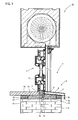
- Fig. 1 shows a composite according to the invention 1 consisting of a window 2 with a window frame 3, a masonry 4 with a masonry reveal 5, in which the window 2 is set, an insulation element 6 according to the invention, which is set between the masonry reveal 5 and the bottom 7 of the window frame 3 and a first window sill 8 arranged on the outside, which abuts against a bank connection 9 projecting on the underside 7 of the window frame 3, and a second inner window sill 10.
- the insulating element 6 is plate-shaped and placed with its flat bottom 11 on the surface of masonry reveal 5. It has a first support section 12, on the upper side of which the first sill 8 is placed. The top is at an angle of about 5 ° to the horizontal, so that automatically results in mounting the sill 8, which is usually made of aluminum, the predetermined inclination angle, see Fig. 1 , At a second support portion 13 sits on the upper side, the second window sill 10, for example, a marble or granite bench. The top of this support portion 13 is horizontal after the inboard sill 10 is not prone.
- a bank connection 9 is arranged on the window frame 3 itself, usually already adhered to the factory.
- the bank connection 9 is an elongated strip, which is designed here as a hollow-chamber strip. It extends from the frame bottom 7 down.
- a receiving groove 14 is provided, the shape and size of the shape and size of the bank connection 9 corresponds, so that it engages in the receiving groove 14 and is preferably non-positively or positively held.
- the first window sill 8 strikes the bank connection 9; it is usually also fixed to it by means of screws.
- the insulating element 6 also has a projection 15 which extends, based on the Dämmelementunterseite, vertically upwards. It has a substantially rectangular geometry. It extends to directly on the underside 7 of the window frame 3, that is, this sits on top of the projection 15, which is why the total insulation element 6 is made of sufficiently pressure-resistant material such as PS or PU.
- the projection 15 is obviously located immediately adjacent to the bank connection 9, this is preferably on the vertical outer side of the projection 15 (in Fig. 1 the right outer side) glued, as appropriate, in the region of the receiving groove 14th
- the projection 15 serves not only as an attachment point for the bank connection 9, but also as a stop for the second sill 10, which can be seen with its frame-side end side rests directly on the projection 15.
- the projection 15 is thus, seen horizontally, set between the first sill 8 respectively the bank connection 9 and the second sill 10. After this he immediately adjacent to the window frame 3, results, seen horizontally, a thermal barrier. A heat transfer from the inside to the outside is here largely prevented, compared with the previous embodiment in the prior art, where no insulating element 6 was used and both sills 8, 10 directly adjacent to the bank connection 9, which was the sole "Dämmelement" in this area ,
- the insulating element 6 is first placed on the reveal inside, preferably glued. Then, the window frame is mounted, wherein the bank connection 9 is inserted into the receiving groove 14 and the insulating element is glued to the frame bottom 7 and the bank connection 9. Then 6 mortar bands 18, 19 are applied to the longitudinal sides 16, 17 of the Dämmelements, after which the two window sills 8 and 10 are set and fixed.
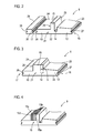
- Fig. 2 shows in an enlarged perspective view of the insulating element 6 Fig. 1 , It has a substantially plate-shaped body 21 with a flat underside 22. Shown is the first support portion 12 with its inclined surface 23 and the second support portion 13 with its flat surface 24. Also shown is the receiving groove 14, as well as the rectangular projection 15 whose vertical outer side 25 limits the receiving groove. On this outside 25 is like Fig. 1 the bank connection 9 indicates.
- the opposite inner side 26 serves as described as a stop surface for the second sill 10th
- each receiving grooves 27, 28 are provided on the two longitudinal sides 16, 17 each receiving grooves 27, 28 are provided. These serve for a better connection with a mortar tape, on the other hand can be done in them, the fixation of an extension member 29.
- an extension member 29 Such is in Fig. 2 additionally shown. It is also made of insulating material and has a spring 30 inserted into the groove 28 (or 27) can be, so that preferably results in a positive or frictional connection.
- a support portion 12, 13 are extended.
- the extension element 29 has a further groove 31, into which the spring 30 of a second extension element 29 can be inserted, so that stepwise any extension of the respective support section can be achieved. If such an extension portion 29 is provided for extending the first, obliquely receiving portion 12, its shape may be adapted to the slope, that is, it may decrease in height to continue the inclined surface 23.
- Fig. 3 shows a further inventive embodiment of a Dämmelements 6, wherein like reference numerals are used for the same components.
- this insulating element 6 has a body 21 with a flat bottom 22 and the two support portions 12, 13 with the located on their longitudinal sides 16, 17 grooves 27, 28. Again, the top 23 of the first receiving portion 12 is made oblique, while the top 24 of the second receiving portion 13 extends horizontally.
- the left inner side 26 again serves as a stop for the second sill.
- the bank connection 9 is arranged in the form of a strip in this embodiment of the invention on the insulating element, which is shown here as a solid material strip, but equally can also be embodied as a hollow-chamber strip.
- the bank connection 9 is integrated on the insulating element 6 itself, the bank connection 9 is glued to the projection 15 expediently.
- a receiving groove 14 may be provided, in which then the vertically seen slightly longer bank connector 9 is inserted, similar to the embodiment of the FIGS.
- the window frame 3 is bankan gleichlos, the connection of the bank connection 9 to the window frame 3 takes place only during the assembly of the window frame, both are glued together.
- the projection 15 here consists of a total of four separate projection portions 15a, 15b, 15c and 15d.
- the projection portion 15a is relatively wide, for example, it has a width of 30 mm.
- Each of the protrusion portions 15b-15d is, for example, 5 mm wide, all the protrusion portions are separated from each other by a narrow gap. It is now possible to gradually adjust the overall width of the projection 15 by separating one or more of the narrow projection portions 15d, 15c, 15b. This can be done by simply canceling or cutting off a projection section. This can be easily adapted to the width of the projection different window frame widths.
- the entire protrusion 15 has an overall width of about 50 mm, with the wide protruding portion 15a having a width of 30 mm and each protruding portion 15b-15d having a width of 5 mm.
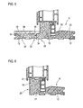
- Fig. 5 shows a further embodiment of a Dämmelements 6 according to the invention
- the underside 22 is structured via a groove structure 32. This can be done even better connection of the Dämmelements 6 with his fixation on the soffit inside serving adhesive or mortar. Such structuring can of course also in the Dämmelementaus exiten the Figures 1 - 4 be provided.
- the top 23 of the outer support portion 12 is designed as an inclined surface as in the other embodiments.
- the inclined surface is in the area that ends adjacent to the projection 15, in a further inclined surface 33, which serves for the simplified assembly of the outer sill 8. This must be brought with its upper edge in the area between the bank connection 9 and the front window frame edge, as in Fig. 1 is shown.
- the sill 8 is slightly tilted introduced from below. In order to be able to swing it down in a simple manner, without any dirt, the is in the area and the like hinders this, this inclined surface 33, which may also be designed as a curve, appropriate.
- the second support portion 13 is provided on its upper side with connecting means in the form of grooves 34 in which springs 35, which are arranged on the underside of a support element 36, engage.
- the support member 36 is a relining mold to slightly raise the support surface for the inner sill. In this way it is possible to mount even narrower, for example, only 22 mm thick window sills, which are then at a correct distance from the lower edge of the window frame.
- the support element is to install if necessary, after it is detachably placed, it is held on the tongue and groove connection either slightly clamped, but can also be glued if necessary.
- Fig. 6 shows an inventive Dämmelement 6, wherein the Dämmelementkorpus 21 only the outer sill 8 receiving support portion 12 and the projection 15 are provided. That is, the second support portion 13 is not provided here.
- This insulating element 6 is particularly suitable in the field of old building renovation, if the inner window sill is not removed and replaced with a new one.
- the projection 15, the here (as well as in the embodiment according to Fig. 5 ) has an upper side groove 37 for receiving a swelling tape, which automatically swells and seals against the frame bottom, has, strikes with its outside 26 against the set still in the soffit inner window sill, only the outer sill 8 is on the support portion 12 worn. Otherwise, the embodiment corresponds as far as in Fig. 5 shown.
- FIG. 7 another embodiment of a Dämmelements 6 with also only the support portion 12 and the projection 15, but here on the projection 15 - comparable to the embodiment according to Fig. 3 -
- a bank connector 9 is arranged in the form of a narrow angle bar, one leg 38 is glued to the outside 25 of the projection, while the other leg 39 engages over the top of the projection 15. On it lies in this embodiment of the window frame.
- the projection 15 as a separate component, which can be plugged into the plate-shaped body.
- a tongue and groove connection such as in the fixation of an extension element, can be used. This makes it possible, for example, to fix different widths or different heights 15 optional.
- the central element according to the invention is the projection 15 which, in comparison to the prior art, is arranged in the area directly below the window frame in addition to the bench connection. This can achieve a significant improvement of the thermal insulation, which is also clearly expressed in the calculated for the respective embodiments heat transfer coefficient U.
Landscapes
- Engineering & Computer Science (AREA)
- Civil Engineering (AREA)
- Structural Engineering (AREA)
- Door And Window Frames Mounted To Openings (AREA)
- Building Environments (AREA)
- Specific Sealing Or Ventilating Devices For Doors And Windows (AREA)
Abstract
Description
Die Erfindung betrifft ein Dämmelement, das zwischen der Unterseite eines Fensterrahmens und dem Laibungsmauerwerk anzuordnen ist.The invention relates to an insulating element which is to be arranged between the underside of a window frame and the reveal masonry.
Ein Fenster wird mit seinem Rahmen bekanntlich in eine Mauerwerkslaibung gesetzt. An den beiden Vertikalseiten und der Oberseite wird die Laibung verputzt, wobei der Putz üblicherweise bis an den Fensterrahmen herangezogen wird. An der Unterseite werden zwei Fensterbände angeordnet, eine Außenfensterbank, beispielsweise eine Aluminiumfensterbank, sowie eine Innenfensterbank, beispielsweise aus Marmor, Granit, Naturstein, Holz oder Holzverbundwerkstoffe. Um die Fensterbänke genau positionieren und im Falle der Außenfensterbank diese befestigen zu können, ist bisher an der Unterseite des Fensterrahmens ein Bankanschluss vorgesehen, üblicherweise in Form einer zumeist hohlkammerigen Leiste, die sich längs des Fensterrahmens erstreckt. Dieser Bankanschluss springt vom Fensterrahmen zum Laibungsmauerwerk vor. Die beiden Fensterbänke werden an beiden Seiten des Bankanschlusses angelegt, die Außenfensterbank üblicherweise daran verschraubt, wobei die Fensterbänke jeweils über entsprechende auf das Laibungsmauerwerk aufgebrachte Mörtelbänder fixiert werden. Der Bankanschluss dient also als Anschlag respektive Befestigungselement für die beiden Fensterbänke.A window is set with its frame known in a masonry reveal. On the two vertical sides and the top of the soffit is plastered, the plaster is usually used up to the window frame. At the bottom of two window bands are arranged, an outside window sill, such as an aluminum sill, and an interior sill, for example, marble, granite, natural stone, wood or wood composites. In order to position the sills exactly and be able to fix them in the case of the outside window sill, a bank connection has heretofore been provided on the underside of the window frame, usually in the form of a mostly hollow-chambered bar which extends along the window frame. This bank connection projects from the window frame to the reveal masonry. The two window sills are placed on both sides of the bank connection, the outside window sill is usually screwed to it, the window sills being fixed in each case via corresponding mortar bands applied to the reveal masonry. The bank connection thus serves as a stop respectively fastening element for the two sills.
Wie beschrieben handelt es sich bei dem Bankanschluss letztlich lediglich um eine relativ schmale, zumeist hohle Leiste, die mit dem Fensterrahmen in der Regel bereits werksseitig verbunden wird. Insbesondere über die Hohlkammerausführung wird eine gewisse Wärmedämmung erzielt. Diese ist jedoch nicht allzu gut, insbesondere, nachdem die beiden Fensterbänke, die beide aus Materialien sind, die gut wärmeleitend sind, direkt anschlagen. Das heißt, dass sich in diesem Bereich eine horizontale Wärmebrücke ergibt, so dass insgesamt gesehen die lokale Wärmedämmung nicht allzu gut ist.As described, the bank connection is ultimately only a relatively narrow, mostly hollow strip, which is usually already connected to the window frame at the factory. In particular, the hollow chamber design, a certain thermal insulation is achieved. However, this is not very good, especially after the two sills, both of which are made of materials that conduct heat well, strike directly. This means that a horizontal thermal bridge results in this area, so that overall the local thermal insulation is not very good.
Der Erfindung liegt damit das Problem zugrunde, eine Möglichkeit anzugeben, mit der auf einfache Weise in diesem Bereich eine gute Wärmedämmung erzielt werden kann.The invention is thus based on the problem of specifying a possibility with which a good thermal insulation can be achieved in a simple manner in this area.
Zur Lösung dieses Problem ist nach einer ersten Erfindungsalternative ein Dämmelement vorgesehen, das zwischen einem Fensterrahmen mit einem an seiner Rahmenunterseite vorspringenden Bankanschluss als Anschlag für eine erste Fensterbank und einem Laibungsmauerwerk anzuordnen ist, wobei sich dieses plattenförmige Dämmelement dadurch auszeichnet, dass wenigstens ein Auflageabschnitt für eine Fensterbank und ein sich über die Elementlänge erstreckender Vorsprung vorgesehen ist, dessen eine Seite in der Montagestellung horizontal gesehen benachbart zum Bankanschluss liegt und dessen andere Seite als Anschlag für eine zweite Fensterbank dient.To solve this problem, an insulating element is provided according to a first alternative of the invention, which is to be arranged between a window frame with a protruding on its underside frame bank connection as a stop for a first sill and a revetment masonry, this plate-shaped insulating element is characterized in that at least one support portion for a Window sill and a projection extending over the length of the element is provided, one side of which, when viewed in the assembled position, lies horizontally adjacent to the bank connection and whose other side serves as a stop for a second sill.
Das erfindungsgemäße Dämmelement ist in dem sensiblen Bereich zwischen Fensterrahmenunterseite und Laibungsmauerwerk anzuordnen und ermöglicht infolge seiner geometrischen Ausgestaltung eine hervorragende Wärmedämmung in horizontaler Richtung. Ermöglicht wird dies einerseits durch die plattenförmige Ausführung des Dämmelements, so dass es flächig auf das Mauerwerk aufgesetzt werden kann und infolge seiner Breite in diesem Bereich eine extrem gute Wärmedämmung bietet. Dem erfindungsgemäß vorgesehenen, sich in der Montagestellung an der Elementoberseite nach oben erstreckenden Vorsprung kommt eine Doppelfunktion zu. Zum einen dient er mit seinen beiden Seiten einerseits als Anlagefläche für den bei dieser Erfindungsausgestaltung respektive dem Einsatzzweck des Dämmelements am Fensterrahmen vorgesehenen Bankanschluss, der in der Montagestellung an der Außenseite des Vorsprungs anliegt. An der Innenseite dient der Vorsprung als Anschlag für die raumseitige Fensterbank. Gleichzeitig wird infolge der vertikalen Erstreckung des Vorsprungs bis zum Fensterrahmen, der auf ihm aufsitzt, eine hervorragende Wärmedämmung in horizontaler Richtung realisiert. Während dem Wärmetransport bisher nur der schmale Bankanschluss entgegengewirkt hat, entfaltet sich in der Montagestellung nun zusätzlich durch die Integration des erfindungsgemäßen Dämmelements auch die hervorragende Dämmeigenschaft des horizontal gesehen benachbart, also mit Blick von der Mauerwerkaußenseite innen hinter dem Bankanschluss liegenden Vorsprungs, so dass sich insgesamt in dieser Horizontalrichtung gesehen eine extreme Verbesserung der Wärmedämmung erreichen lässt. Der Bankanschluss liegt an der Außenseite des Vorsprungs, so dass über ihn zur Wetterseite hin abgedichtet wird. Das Dämmelement selbst kann aus einem beliebigen Dämmstoff wie Polystyrol unterschiedlichste Ausführung oder Polyurethan oder sonstigen insbesondere schäumbaren Dämmstoffen bestehen.The insulation element according to the invention is to be arranged in the sensitive area between the underside of the window frame and reveal masonry and, due to its geometric configuration, enables excellent thermal insulation in the horizontal direction. This is made possible on the one hand by the plate-shaped design of the Dämmelements so that it can be placed flat on the masonry and offers an extremely good thermal insulation due to its width in this area. The inventively provided, in the mounting position on the top of the element upwardly extending projection has a dual function. On the one hand, it serves with its two sides, on the one hand, as a contact surface for the bank connection provided in this embodiment of the invention or the intended use of the insulating element on the window frame, which rests on the outside of the projection in the assembly position. On the inside of the projection serves as a stop for the room-side windowsill. At the same time an excellent thermal insulation is realized in the horizontal direction due to the vertical extent of the projection to the window frame, which rests on him. While only the narrow bank connection has hitherto been counteracted during the transport of heat, in the assembly position now, in addition to the integration of the insulating element according to the invention, the outstanding insulating property of the horizontally adjacent one also unfolds, ie with a view from the masonry outside inside behind the bank connection lying projection, so that in total seen in this horizontal direction can achieve an extreme improvement in thermal insulation. The bank connection is located on the outside of the projection, so that it is sealed over it to the weather side. The insulating element itself may consist of any insulating material such as polystyrene different designs or polyurethane or other foamable in particular insulating materials.
Eine zweckmäßige Erfindungsausgestaltung dieser ersten Ausführungsalternative sieht vor, dass benachbart zum Vorsprung eine Aufnahmenut vorgesehen ist, in die der Bankanschluss in der Montagestellung eingreift. Das heißt, dass der Bankanschluss, der bisher über seine gesamte vertikale Länge eine Wärmesenke dargestellt hat, zusätzlich mit seinem unteren Ende in einer Nut aufgenommen ist, die ihn, gesehen von der Mauerwerkaußenseite, bevorzugt um wenigstens die Hälfte seiner vertikalen Länge aufnimmt, so dass nur noch ein sehr kurzer Höhenabschnitt des Bankanschlusses nicht vom Dämmmaterial umgeben ist. Darüber hinaus lässt sich auf diese Weise auch eine sehr einfache Ausrichtung des Dämmelements zum Fensterrahmen erreichen. Bevorzugt greift der Bankanschluss in einem form- oder kraftschlüssigen Verbund in die Nut ein, in der gegebenenfalls auch ein dichtendes Quellband aufgenommen sein kann.An expedient embodiment of this first alternative embodiment provides that a receiving groove is provided adjacent to the projection, into which the bank connection engages in the assembly position. This means that the bank connection, which has so far represented a heat sink over its entire vertical length, is additionally accommodated with its lower end in a groove which, viewed from the outside of the masonry, preferably receives it by at least half of its vertical length, so that only a very short height section of the bank connection is not surrounded by the insulating material. In addition, can be achieved in this way, a very simple alignment of the Dämmelements the window frame. Preferably, the bank connection engages in a positive or non-positive bond in the groove, in which optionally also a sealing swelling tape may be received.
Eine zweite grundlegende Erfindungsalternative eines Dämmelements ist zur Verwendung mit einem Fensterrahmen geeignet, der keinen Bankanschluss aufweist. Ein derart geeignetes Dämmelement zeichnet sich dadurch aus, dass es ebenfalls plattenförmig ausgeführt ist und wenigstens einen Auflageabschnitt für eine Fensterbank und einen sich über die Elementlänge erstreckenden Vorsprung aufweist, an dessen einen Seite ein als Anschlag für die erste Fensterbank dienender Bankanschluss angeordnet ist und dessen andere Seite als Anschlag für die zweite Fensterbank dient.A second basic invention alternative of an insulating element is suitable for use with a window frame which has no bank connection. Such a suitable insulating element is characterized in that it is also designed plate-shaped and has at least one support portion for a sill and extending over the length element projection on one side serving as a stop for the first sill bank connector is arranged and the other Side serves as a stop for the second sill.
Bei dieser zweiten grundlegenden Erfindungsausführung ist der Bankanschluss, bei dem es sich letztlich infolge der Integration des Dämmelements in diesem thermisch sensiblen Bereich nur noch um eine hinreichend stabile, ein Verschrauben der Außenfensterbank ermöglichendes Bauteil handelt, am Wärmedämmelement selbst angeordnet bzw. dort integriert, bevorzugt angeklebt. Das heißt, dass rahmenseitig kein separater Bankanschluss mehr vorgesehen werden muss, vielmehr ist das Dämmelement ein vorkonfiguriertes Bauteil mit integriertem Bankanschluss, der bevorzugt in Form einer Kunststoffleiste ausgeführt ist und am an der Elementoberseite abstehender Vorsprung außenseitig angeklebt ist. Eine solche, gegebenenfalls als Winkel ausgeführte Leiste ohne Hohlkammer ist die einfachste Ausführungsform eines Bankanschlusses, eine Stärke von beispielsweise 5 mm ist ausreichend, die Außenfensterbank daran anschrauben zu können. Selbstverständlich kann auch eine etwas stärkere hohle Kunststoffleiste mit einer Stärke von z. B. 10 mm oder 15 mm als Bankanschluss verwendet werden. Im Rahmen der Montage ist in diesem Fall lediglich der Bankanschluss mit seiner Oberseite oder im Kantenbereich mit dem Fensterrahmen zu verbinden, üblicherweise zu verkleben, während bei der ersten Ausführungsform der rahmenseitig vorgesehene Bankanschluss mit dem Dämmelement im Bereich des Vorsprungs respektive im Bereich der Aufnahmenut verklebt wird.In this second basic embodiment of the invention, the bank connection, which is ultimately due to the integration of Dämmelements in this thermally sensitive area only to a sufficiently stable, a screwing the exterior window sill enabling component is arranged on the heat-insulating element itself or integrated there, preferably glued. This means that no separate bank connection must be provided on the frame side, rather, the insulating element is a preconfigured component with integrated bank connection, which is preferably designed in the form of a plastic strip and is adhered to the outside protruding on the top of the element. Such, optionally executed as an angle bar without a hollow chamber is the simplest embodiment of a bank connection, a thickness of, for example, 5 mm is sufficient to screw the outside windowsill can. Of course, a slightly stronger hollow plastic strip with a thickness of z. B. 10 mm or 15 mm can be used as a bank connection. As part of the assembly in this case, only the bank connection with its top or in the edge region with the window frame to connect, usually stick, while glued in the first embodiment, the frame side provided bank connection with the insulating element in the region of the projection respectively in the region of the receiving groove ,
Diese Erfindungsalternative lässt in gleicher Weise eine hervorragende Dämmung in diesem Bereich zu, da auch hier der zentrale Vorsprung vorgesehen ist, der wiederum benachbart zum dämmelementseitig integrierten Bankanschluss liegt, so dass keine Wärmesenke in horizontaler Richtung auch bei Anordnung der Fensterbänke, die wiederum im Falle der Außenbank an den dämmelementseitig integrierten Bankanschluss bzw. im Falle der Innenbank an den Vorsprung selbst anschlagen, gegeben ist.This invention alternative allows in the same way excellent insulation in this area, since here the central projection is provided, which in turn is adjacent to the insulation element integrated bank connection, so that no heat sink in the horizontal direction even with the arrangement of window sills, which in turn in the case of External bench on the insulation element side integrated bank connection or in the case of the inner bank to the projection itself strike given is.
Ein weiterer Vorteil der Zwischenschaltung des Vorsprungs innerhalb dieses horizontalen Aufbaus liegt darin, dass die Innenfensterbank kürzer ausgeführt werden kann, nachdem diese nicht mehr wie bisher bis an den Bankanschluss zu führen ist. Vielmehr kann die Banklänge um die Breite des Vorsprungs verkürzt werden, also beispielsweise bei einer Vorsprungbreite von 30 mm um eben dieses Maß, so dass weniger Material verbraucht wird bzw. die Fensterbank insgesamt etwas kostengünstiger hergestellt werden kann.Another advantage of the interposition of the projection within this horizontal structure is that the inner window sill can be made shorter, after this is no longer as before to lead to the bank connection. Rather, the bank length can be shortened by the width of the projection, so for example at a projection width of 30 mm by just this measure, so that less material is consumed or the sill can be made a little cheaper overall.
Wie beschrieben ist in der einfachsten Ausführung nur ein Auflageabschnitt für eine Fensterbank vorgesehen, der sich horizontal vom Vorsprung weg erstreckt. Ein solches Dämmelement eignet sich sehr gut im Bereich der Altbausanierung, da hierbei beim Setzen eines neuen Fensters nicht immer z.B. die innere Fensterbank ausgetauscht wird. Diese bleibt verbaut, der Vorsprung des montierten Dämmelements schlägt gleichwohl an die Fensterbank an. Lediglich die Außenfensterbank wird von dem einen vorgesehenen Auflageabschnitt getragen. Gleichermaßen verwendbar ist solch ein Dämmelement auch dann, wenn die Außenfensterbank nicht getauscht wird, es ist dann nur ein Auflageabschnitt für die Innenfensterbank vorgesehen.As described, in the simplest embodiment, only one support section for a sill is provided which extends horizontally away from the projection. Such an insulating element is very well suited in the field of old building renovation, since in setting a new window this is not always the case, for example. the inner windowsill is replaced. This remains installed, the projection of the mounted Dämmelements nevertheless strikes the windowsill. Only the outer window sill is supported by the one provided support portion. Equally usable is such an insulating element even if the outer window sill is not exchanged, it is then only provided a support portion for the inner sill.
Ein vor allem im Neubaubereich einsetzbares Dämmelement zeichnet sich durch zwei separate Auflageabschnitte für jeweils eine Fensterbank aus, d.h. dass hierbei beide Fensterbänke von je einem Auflageabschnitt getragen sind. Mit den beiden Auflageabschnitten kann, da horizontal gesehen die Dämmstofflänge noch größer ist, die Dämmung noch weiter verbessert werden.An insulating element, which can be used above all in the new building sector, is distinguished by two separate support sections for one window sill in each case, i. that in this case both sills are each supported by a support section. With the two support sections, since the insulation material length is even larger horizontally, the insulation can be further improved.
Wie bereits beschrieben, sind dämmelementseitig ein oder zwei Auflageabschnitte für eine oder beide Fensterbänke vorgesehen, die unmittelbar auf der Oberseite des jeweiligen Auflageabschnitts aufliegen. Gemäß einer besonders zweckmäßigen Ausgestaltung beider Erfindungsalternativen ist vorgesehen, dass die Oberseite des einen Auflageabschnitts, der der Aufnahme der Außenfensterbank dient, unter einem Winkel zur Horizontalen oder, wenn der zweite Auflageabschnitt vorgesehen ist, zur Oberseite des anderen Auflageabschnitts verläuft, sie ist also als Schrägfläche ausgeführt. Üblicherweise muss eine Außenfensterbank unter einem Winkel von wenigen, in der Regel 5° zur Horizontalen geneigt verlaufen, so dass anstehendes Wasser, sei es Schlagregen oder Kondenswasser, vom Fenster weg ablaufen kann. Erfindungsgemäß ist nun vorgesehen, die Oberseite des Auflageabschnitts, der diese Außenfensterbank aufnimmt, bereits angeschrägt, also mit diesem vorgegebenen Winkel auszuführen, so dass die darauf aufgesetzte Fensterbank automatisch im definierten, vorgegebenen Winkel zur Horizontalen angeordnet ist. Die Oberseite des gegebenenfalls vorgesehenen anderen Auflageabschnitts verläuft in der Regel horizontal, nachdem sich die von ihm getragene Fensterbank im Rauminneren befindet und eine Neigung nicht erforderlich ist.As already described, one or two support sections for one or both window sills are provided on the damping element side, which rest directly on the upper side of the respective support section. According to a particularly expedient embodiment of both invention alternatives is provided that the top of a support section, which serves to receive the window sill, at an angle to the horizontal or, if the second support section is provided to the top of the other support section, so it is as an inclined surface executed. Usually, an outdoor window sill must be inclined at an angle of a few, usually 5 ° to the horizontal, so that pending water, whether driving rain or condensation, can run away from the window. According to the invention, it is now provided that the upper side of the support section, which accommodates this outer window sill, is already bevelled, that is to run at this predetermined angle, so that the window sill mounted thereon is automatically arranged at the defined, predetermined angle to the horizontal. The top of the optionally provided other support section usually runs horizontally, after the windowsill worn by him is inside the room and a slope is not required.
Ferner kann die Schrägfläche im Bereich benachbart zum Vorsprung in eine zweite Schrägfläche mit entgegengesetzter Neigung oder eine Rundung übergehen. Diese weitere Schrägfläche oder Rundung ermöglicht ein leichteres Einschieben der äußeren Fensterbank, die mit ihrer vorderen Oberkante zwischen einen Außensteg des Fensterrahmens und den Bankanschluss zu bringen ist. Die Schrägfläche oder Rundung ermöglicht ein einfaches Einschwenken in die Endstellung, etwaiger Schmutz etc. kann, da die Schrägfläche oder Rundung ausreichend Platz bietet, diese Bewegung nicht behindern.Further, the inclined surface in the region adjacent to the projection in a second inclined surface with opposite inclination or a rounding pass. This further inclined surface or rounding allows easier insertion of the outer window sill, which is to bring with its front upper edge between an outer web of the window frame and the bank connection. The oblique surface or rounding allows easy pivoting into the end position, any dirt, etc., since the inclined surface or rounding provides sufficient space, this movement does not hinder.
Der Vorsprung selbst sollte eine Breite von 25 - 50 mm, insbesondere von ca. 30 mm aufweisen, wobei der Vorsprung auch durchaus breiter als 50 mm sein kann, je nachdem, wie breit der Fensterrahmen tatsächlich ist. Bei üblichen Standardfensterrahmen beträgt die Rahmenstärke ca. 70 mm, weshalb eine Vorsprungbreite von ca. 30 mm ausreichend ist. Jedoch können bei sehr breiten Rahmen, wie sie beispielsweise für sehr große Fenster mitunter auch als Sonderanfertigungen zum Einsatz kommen, durchaus auch Vorsprünge verwendet werden, die deutlich breiter als 50 mm sind.The projection itself should have a width of 25-50 mm, in particular of about 30 mm, wherein the projection may well be wider than 50 mm, depending on how wide the window frame is actually. For standard window frames, the frame thickness is about 70 mm, which is why a projection width of about 30 mm is sufficient. However, in the case of very wide frames, such as are sometimes used for very large windows as custom-made designs, it is certainly also possible to use projections which are significantly wider than 50 mm.
Um die Möglichkeit zu geben, die Vorsprungbreite auf einfache Weise variieren zu können, sieht eine Erfindungsausgestaltung vor, dass der Vorsprung aus einem ersten breiten Vorsprungabschnitt und einem oder mehreren an einer Seite parallel dazu verlaufenden weiteren, jedoch schmäleren Vorsprungabschnitten besteht. Diese mehrteilige Ausführungsform des Vorsprungs ist dahingehend von Vorteil, als ohne weiteres ein solcher schmaler Vorsprungabschnitt abgetrennt werden kann, so dass sich die tatsächliche Vorsprungbreite von einer maximalen Breite, definiert durch den ersten breiten Vorsprungabschnitt und sämtliche vorgesehenen schmäleren Abschnitte, bis zu einer minimalen Breite, definiert nur durch den ersten Breitenvorsprungabschnitt, über die einzelnen Abtrennstufen variieren lässt. Die einzelnen Vorsprungabschnitte sind beispielsweise über einen sehr schmalen Spalt voneinander getrennt. Beispielsweise kann der breite Vorsprungabschnitt 30 mm stark sein, jeder weitere schmälere Vorsprungabschnitt 5 mm, bei ca. 1 mm Abstand zwischen den einzelnen Abschnitten. Die Abtrennung kann mühelos mit einem Messer oder dergleichen Werkzeug oder durch Abbrechen (gegebenenfalls entlang einer Sollbruchlinie am Vorsprungabschnitt) erfolgen.In order to be able to vary the projection width in a simple manner, an embodiment of the invention provides that the projection consists of a first broad projection section and one or more further, but narrower projection sections running parallel to one side. This multi-part embodiment of the protrusion is advantageous in that such a narrow protruding portion can be easily separated so that the actual protrusion width is limited from a maximum width defined by the first broad protruding portion and all narrower portions provided to a minimum width. defined only by the first width projection portion, can vary over the individual separation stages. The individual projecting portions are separated from one another, for example, by a very narrow gap. For example, the wide projecting
Das erfindungsgemäße Dämmelement ist sowohl im Neubaubereich als auch im Bereich der Altbausanierung ohne weiteres einsetzbar. Insbesondere im Bereich der Altbausanierung sind häufig sehr starke Laibungen geben, mit Mauerstärken bis zu 40 cm und mehr. Um die Möglichkeit einer breitenmäßigen Anpassung des Dämmelements, das standardisiert beispielsweise eine Breite von wenigstens 15 cm, insbesondere von wenigstens 20 cm aufweist, zu geben, ist erfindungsgemäß vorgesehen, an einer Längsseite des Dämmelements einen Verlängerungsabschnitt anzubringen. Ein solcher Verlängerungsabschnitt kann beispielsweise eine Breite von 5 cm aufweisen. Bei einer Standardbreite von 20 cm kann so das Dämmelement mit zwei Verlängerungsabschnitten an beiden Seiten um 10 cm auf insgesamt 30 cm verlängert werden, so dass bei einer Mauerstärke von 40 cm beidseits des Dämmelements jeweils nur ca. 5 cm Abstand zur Mauerfläche verbleiben, wo dann das anschließende Mörtelband aufgebracht werden kann. Zum einen kann hierüber die horizontale Breite des Dämmelements vergrößert werden, zum anderen die Breite des aufzubringenden Mörtelbandes, so dass weniger Mörtel zu wenden ist. Während obiges Beispiel von einer im Wesentlichen mittigen Anordnung des Fensterrahmens bezogen auf die Laibungstiefe ausgeht, ist es selbstverständlich denkbar, das Dämmelement auch außermittig zu setzen, sofern dies beispielsweise aufgrund des verwendeten Rollokastens oder dergleichen erforderlich ist. In diesem Fall ist es möglich, einen Verlängerungsabschnitt auch nur an einer Seite anzubringen bzw. an einen Verlängerungsabschnitt einen weiteren Verlängerungsabschnitt anzusetzen, um horizontal gesehen aufzubauen. Die Befestigung eines Verlängerungsabschnitts an einer Längsseite erfolgt zweckmäßigerweise über an beiden vorgesehene Verbindungsmittel, insbesondere in Form von Nut und Feder oder dergleichen, wobei auf diese Weise natürlich auch zwei Verlängerungsabschnitte miteinander gekoppelt werden können. Alternativ dazu besteht selbstverständlich immer die Möglichkeit, die Bauteile miteinander zu verkleben.The insulation element according to the invention can be used readily in new construction as well as in the field of old building renovation. Especially in the field of old building renovation are often very strong reveals, with wall thicknesses up to 40 cm and more. In order to give the possibility of a broad adaptation of Dämmelements, the standardized, for example, a width of at least 15 cm, in particular of at least 20 cm, is provided according to the invention to attach to a longitudinal side of the Dämmelements an extension section. Such an extension section may for example have a width of 5 cm. With a standard width of 20 cm, the insulation element with two extension sections on both sides can be extended by 10 cm to a total of 30 cm, so that with a wall thickness of 40 cm on both sides of the Dämmelements each only about 5 cm distance to the wall surface remain where then the subsequent mortar tape can be applied. On the one hand, the horizontal width of the Dämmelements be increased here, on the other hand, the width of the applied mortar tape, so that less mortar is to turn. While the above example of a substantially central arrangement of the window frame based on the reveal depth, it is of course conceivable to set the insulating element off-center, if this is necessary, for example, due to the Rollokastens or the like. In this case, it is also possible to attach an extension section only on one side or to attach an extension section to a further extension section in order to build it up horizontally. The attachment of an extension portion on one longitudinal side is expediently carried out on both provided connecting means, in particular in the form of tongue and groove or the like, wherein in this way, of course, two extension sections can be coupled together. Alternatively, of course, there is always the possibility to glue the components together.
Um sofern erforderlich die Höhe eines Auflageabschnitts, insbesondere des die innere Fensterbank tragenden Auflageabschnitts anpassen zu können, sieht eine Weiterbildung der Erfindung ein Auflageelement vor, das lösbar an einem Auflageabschnitt, insbesondere dem innern Auflageabschnitt, anbringbar ist. Dies geschieht vorzugsweise über am Auflageabschnitt und am Auflageelement vorgesehene Verbindungsmittel, insbesondere in Form von Nut und Feder, so dass beide einfach ineinander eingesteckt und gegebenenfalls verklebt werden können. Die Fixierung kann aber auch nur durch Verkleben erfolgen.In order to be able to adjust the height of a support section, in particular of the support section supporting the inner window sill, a further development of the invention provides a support element that can be detachably attached to a support section, in particular the inner support section. This is preferably done via provided on the support portion and the support element connecting means, in particular in the form of tongue and groove, so that both can be easily inserted into one another and optionally glued. The fixation can also be done only by gluing.
Das Dämmelement sollte eine Länge von wenigstens 25 cm, insbesondere von 50 cm oder 100 cm aufweisen. Üblicherweise ist eine Mauerwerkslaibung etwas mehr als 1 m breit, so dass bei einer Bemessung des Dämmelements von beispielsweise 50 cm ohne weiteres zwei Dämmelemente, die mittig miteinander verklebt werden, gesetzt werden können. Das Dämmelement kann aber auch z. B. 125 cm lang sein, so dass es durch Ablängen ohne weiteres der Laibungslänge angepasst werden kann, oder zwei derart lange Dämmelemente z. B. eine 250 cm Laibung auskleiden. Die tatsächliche Länge ist stets so zu wählen, dass ohne weiteres eine Stückelung, gegebenenfalls durch Ablängen des Dämmelements, was ohne weiteres möglich ist, erfolgen kann. Wie das Dämmelement in der Länge ablängbar ist, ist es ohne weiteres auch in der Breite ablängbar, das heißt, dass der eine oder andere Auflageabschnitt ohne weiteres über seine Länge gesehen verkürzt werden kann, wenn dies infolge der Position der Anordnung des Fensterrahmens relativ zu Mauerwerkslaibung und die Laibungstiefe erforderlich ist. Denn es ist sicherzustellen, dass die beiden Längsseiten des Dämmelements stets einen gewissen Abstand zur Mauerwerkskante haben, um dort die beiden Mörtelbänder, die die jeweilige Fensterbank mittragen, aufbringen zu können.The insulating element should have a length of at least 25 cm, in particular 50 cm or 100 cm. Typically, a masonry reveal is just over 1 m wide, so that when dimensioning the Dämmelements of example 50 cm easily two insulation elements that are glued together in the middle, can be set. The insulating element but also z. B. 125 cm long, so that it can be easily adjusted by cutting the soffit length, or two such long insulating elements z. B. lining a 250 cm reveal. The actual length is always to be chosen so that a denomination, possibly by cutting the Dämmelements, which is readily possible, can be done without further notice. As the insulation element is cut to length, it is readily cut in width, that is, one or the other support portion can be shortened seen easily over its length, if this is due to the position of the arrangement of the window frame relative to masonry reveal and the reveal depth is required. For it must be ensured that the two longitudinal sides of the insulating element always have a certain distance from the masonry edge, in order to be able to apply the two mortar tapes which support the respective window sill.
Zur Verbesserung der Verankerung des Dämmelements in der Klebe-, Mörtel- oder Schaumschicht auf der Laibungsinnenseite kann die Unterseite des Dämmelements strukturiert sein, was insbesondere über eine Nut- oder Zahnstruktur realisiert sein kann. In diese Struktur dringt der zähe Kleber, Mörtel oder Schaum ein, worüber sich eine gute Verbindung erzielen lässt.To improve the anchoring of the insulating element in the adhesive, mortar or foam layer on the soffit inside the underside of the Dämmelements can be structured, which can be realized in particular via a groove or tooth structure. In this structure penetrates the tough glue, mortar or foam, which can be achieved via a good connection.
Neben dem erfindungsgemäßen Dämmelement selbst betrifft die Erfindung einen Verbund aus Fensterrahmen und Laibungsmauerwerk mit einem zwischen der Unterseite des Fensterrahmens und einem Laibungsmauerwerk angeordneten Dämmelement der beschriebenen Art, an welchem Dämmelement am einen Auflageabschnitt eine erste Fensterbank und am anderen Auflageabschnitt eine zweite Fensterbank angeordnet ist. Dabei kann bei dem erfindungsgemäßen Verbund entweder der Bankanschluss am Fensterrahmen selbst angeordnet sein, so dass ein Dämmelement der ersten Basisausführung eingesetzt wird, wie auch der Fensterrahmen ohne Bankanschluss ausgeführt sein kann, wobei dann der Bankanschluss dämmelementseitig integriert ist, mithin also ein Dämmelement der zweiten Basisausführung eingesetzt wird.In addition to the insulation element according to the invention itself, the invention relates to a composite of window frame and reveal masonry with an arranged between the underside of the window frame and a reveal masonry insulation element of the type described, on which insulating element on a support portion a first sill and the other support portion a second sill is arranged. In this case, in the composite according to the invention, either the bank connection can be arranged on the window frame itself, so that an insulating element of the first basic design is used, as well as the window frame can be designed without bank connection, in which case the bank connection is integrated dämmelementseitig, thus an insulating element of the second basic version is used.
Ist am Fensterrahmen ein Bankanschluss vorgesehen, so ist dieser erfindungsgemäß formschlüssig und/oder kraftschlüssig in der am Dämmelement vorgesehenen Aufnahmenut aufgenommen. Der rahmenseitig vorgesehene Bankanschluss ist weiterhin in der Montagestellung mit dem Dämmelement verklebt, entweder im Bereich der vertikalen Stirnfläche des Vorsprungs oder im Bereich der Aufnahmenut oder in beiden Bereichen. Ist der Bankanschluss dämmelementseitig vorgesehen, so ist der am Dämmelement vorgesehene Bankanschluss mit dem Fensterrahmen verklebt.If a bank connection is provided on the window frame, then it is accommodated positively and / or non-positively in the receiving groove provided on the insulating element. The frame side provided bank connection is further glued in the mounting position with the insulating element, either in the region of the vertical end face of the projection or in the region of the receiving groove or in both areas. If the bank connection is provided on the insulating element side, the bank connection provided on the insulating element is glued to the window frame.
Die Fensterbänke selbst sind am zweckmäßigsten mit den Aufnahmeabschnitten verklebt, wobei üblicherweise die Außenfensterbank, insbesondere wenn diese aus Aluminium ist, zusätzlich mit dem Bankanschluss verschraubt ist.The sills themselves are most conveniently glued to the receiving portions, usually the outer sill, especially if it is made of aluminum, is additionally bolted to the bank connection.
An den Längsseiten des Dämmelements oder gegebenenfalls eines oder beider Verlängerungselemente schließt schließlich jeweils ein Mörtelband an, das die jeweilige Fensterbank zusätzlich trägt.On the long sides of the Dämmelements or possibly one or both extension elements finally includes in each case a mortar tape, which additionally carries the respective sill.
Weitere Vorteile, Merkmale und Einzelheiten der Erfindung ergeben sich aus den im Folgenden beschriebenen Ausführungsbeispielen sowie anhand der Zeichnungen. Dabei zeigen:
- Fig. 1
- eine Prinzipdarstellung eines erfindungsgemäßen Verbundes mit integriertem erfindungsgemäßen Dämmelement,
- Fig. 2
- eine Perspektivansicht des Dämmelements aus
Fig. 1 , - Fig. 3
- eine Perspektivansicht eines Dämmelements einer zweiten Ausführungsform,
- Fig. 4
- eine Perspektivansicht eines Dämmelements einer dritten Ausführungsform,
- Fig. 5
- eine Schnittansicht eines Dämmelements einer vierten Ausführungsform,
- Fig. 6
- eine Schnittansicht eines Dämmelements einer fünften Ausführungsform, und
- Fig. 7
- eine Schnittansicht eines Dämmelements einer sechsten Ausführungsform.
- Fig. 1
- a schematic diagram of a composite according to the invention with integrated insulation element according to the invention,
- Fig. 2
- a perspective view of the Dämmelements
Fig. 1 . - Fig. 3
- a perspective view of an insulating element of a second embodiment,
- Fig. 4
- a perspective view of a Dämmelements a third embodiment,
- Fig. 5
- a sectional view of a Dämmelements a fourth embodiment,
- Fig. 6
- a sectional view of a Dämmelements a fifth embodiment, and
- Fig. 7
- a sectional view of an insulating element of a sixth embodiment.
Das erfindungsgemäße Dämmelement 6 ist plattenförmig und mit seiner ebenen Unterseite 11 auf die Fläche der Mauerwerkslaibung 5 aufgesetzt. Es weist einen ersten Auflageabschnitt 12 auf, auf dessen Oberseite die erste Fensterbank 8 aufgesetzt ist. Die Oberseite verläuft unter einem Winkel von ca. 5° zur Horizontalen, so dass sich automatisch bei Montage der Fensterbank 8, die üblicherweise aus Aluminium besteht, der vorbestimmte Neigungswinkel ergibt, siehe
Am Fensterrahmen 3 selbst ist wie beschrieben ein Bankanschluss 9 angeordnet, üblicherweise bereits werkseitig angeklebt. Der Bankanschluss 9 ist eine längliche Leiste, die hier als Hohlkammerleiste ausgeführt ist. Sie erstreckt sich von der Rahmenunterseite 7 nach unten. Am Dämmelement 6 ist eine Aufnahmenut 14 vorgesehen, deren Form und Größe der Form und Größe des Bankanschlusses 9 entspricht, so dass dieser in die Aufnahmenut 14 eingreifen und in ihr bevorzugt kraft- oder formschlüssig gehaltert ist. Am Bankanschluss 9 schlägt wie beschrieben die erste Fensterbank 8 an, sie ist an ihm üblicherweise auch mittels Schrauben fixiert.As described, a
Das Dämmelement 6 weist ferner einen Vorsprung 15 auf, der sich, bezogen auf die Dämmelementunterseite, vertikal nach oben erstreckt. Er weist eine im Wesentlichen rechteckige Geometrie auf. Er erstreckt sich bis unmittelbar an die Unterseite 7 des Fensterrahmens 3, das heißt, dieser sitzt auf der Oberseite des Vorsprungs 15 auf, weshalb insgesamt das Dämmelement 6 aus hinreichend druckfestem Material wie beispielsweise PS oder PU ist. Der Vorsprung 15 liegt ersichtlich unmittelbar benachbart zum Bankanschluss 9, dieser ist bevorzugt an der vertikalen Außenseite des Vorsprungs 15 (in
Der Vorsprung 15 dient nicht nur als Anlagepunkt für den Bankanschluss 9, sondern auch als Anschlag für die zweite Fensterbank 10, die ersichtlich mit ihrer rahmenseitigen Stirnseite unmittelbar am Vorsprung 15 anliegt.The
Der Vorsprung 15 ist also, horizontal gesehen, zwischen die erste Fensterbank 8 respektive den Bankanschluss 9 sowie die zweite Fensterbank 10 gesetzt. Nachdem er unmittelbar an den Fensterrahmen 3 angrenzt, ergibt sich, horizontal gesehen, eine Wärmeschranke. Ein Wärmeübergang von innen nach außen wird hierüber weitgehend unterbunden, verglichen mit der bisherigen Ausgestaltung im Stand der Technik, wo keinerlei Dämmelement 6 eingesetzt wurde und beide Fensterbänke 8, 10 unmittelbar an den Bankanschluss 9 angrenzen, der das alleinige "Dämmelement" in diesem Bereich war.The
Im Rahmen der Montage wird zunächst das Dämmelement 6 auf die Laibungsinnenseite gesetzt, vorzugsweise angeklebt. Sodann wird der Fensterrahmen montiert, wobei der Bankanschluss 9 in die Aufnahmenut 14 eingesetzt wird und das Dämmelement mit der Rahmenunterseite 7 respektive dem Bankanschluss 9 verklebt wird. Sodann werden an die Längsseiten 16, 17 des Dämmelements 6 anschließende Mörtelbänder 18, 19 aufgebracht, wonach die beiden Fensterbänke 8 und 10 gesetzt und fixiert werden.As part of the assembly, the insulating
Der Vollständigkeit halber ist in der Schnittansicht gemäß
An den beiden Längsseiten 16, 17 sind jeweils Aufnahmenuten 27, 28 vorgesehen. Diese dienen zum einen der besseren Verbindung mit einem Mörtelband, zum anderen kann in ihnen auch die Fixierung eines Verlängerungselements 29 erfolgen. Ein solches ist in
Auch hier ist ein Vorsprung 15 vorgesehen, dessen linke Innenseite 26 wiederum als Anschlag für die zweite Fensterbank dient. An der gegenüberliegenden Außenseite ist bei dieser Erfindungsausgestaltung am Dämmelement folglich selbst der Bankanschluss 9 in Form einer Leiste angeordnet, die hier als Vollmaterialleiste dargestellt ist, gleichermaßen jedoch auch als Hohlkammerleiste ausgeführt sein kann. Das heißt, dass hier der Bankanschluss 9 am Dämmelement 6 selbst integriert ist, der Bankanschluss 9 ist mit dem Vorsprung 15 zweckmäßigerweise verklebt. Wie gestrichelt dargestellt ist, könnte auch eine Aufnahmenut 14 vorgesehen sein, in die der dann vertikal gesehen etwas längere Bankanschluss 9 eingesteckt wird, ähnlich wie bei der Ausgestaltung nach den
Schließlich zeigt
Die Oberseite 23 des äußeren Auflageabschnitts 12 ist wie bei den anderen Ausführungsformen auch als Schrägfläche ausgeführt. Die Schrägfläche geht im Bereich, der benachbart zum Vorsprung 15 endet, in eine weitere Schrägfläche 33 über, die der vereinfachten Montage der äußeren Fensterbank 8 dient. Diese muss mit ihrer Oberkante in den Bereich zwischen dem Bankanschluss 9 und der vorderen Fensterrahmenkante gebracht werden, wie in
Weiterhin ist der zweite Auflageabschnitt 13 an seiner Oberseite mit Verbindungsmitteln in Form von Nuten 34 versehen, in die Federn 35, die an der Unterseite eines Auflageelements 36 angeordnet sind, eingreifen. Das Auflageelement 36 ist ein Unterfütterungsformteil, um die Auflageoberfläche für die innere Fensterbank etwas anzuheben. Auf diese Weise ist es möglich, auch schmälere, beispielsweise nur 22 mm starke Fensterbänke montieren zu können, die dann in einen korrekten Abstand zur Unterkante des Fensterrahmens liegen. Das Auflageelement ist bei Bedarf anzubringen, nachdem es lösbar aufsetzbar ist, es wird über die Nut-Feder-Verbindung entweder leicht klemmend gehalten, kann aber auch gegebenenfalls angeklebt werden. Über eine reine Klebeverbindung kann selbstverständlich auch ein nicht mit entsprechenden Verbindungsmitteln versehenes Unterfütterungsformteil aufgebracht werden.Furthermore, the
Schließlich zeigt
Abschließend ist festzuhalten, dass es grundsätzlich auch denkbar wäre, den Vorsprung 15 insgesamt als separates Bauteil auszuführen, das an dem plattenförmigen Korpus angesteckt werden kann. Hierbei kann wiederum eine Nut-Feder-Verbindung, wie beispielsweise bei der Fixierung eines Verlängerungselements, genutzt werden. Dies ermöglicht es beispielsweise, unterschiedlich breite oder unterschiedlich hohe Vorsprünge 15 wahlweise fixieren zu können.Finally, it should be noted that it would also be conceivable in principle to execute the
Wie beschrieben ist das zentrale erfindungsgemäße Element der Vorsprung 15, der, verglichen mit dem bisherigen Stand der Technik, zusätzlich zum Bankanschluss im Bereich direkt unterhalb des Fensterrahmens angeordnet ist. Hierüber lässt sich eine wesentliche Verbesserung der Wärmedämmung erreichen, die sich auch eindeutig im für die jeweiligen Ausgestaltungen berechenbaren Wärmedurchgangskoeffizienten U ausdrückt.As described, the central element according to the invention is the
Der Wärmedurchgangskoeffizient U berechnet sich wie folgt: 
mit
- U = Wärmedurchgangskoeffizient in W/m2K
- Rse = äußerer Wärmeübergangswiderstand in m2 K/W
- Rsi = innerer Wärmeübergangswiderstand in m2 K/W
- d1 = Schichtdicke einer ersten Schicht in m
- λ1 = spezifische Wärmeleitfähigkeit des Materials der ersten Schicht in W/m K
- d2 ..... n = Schichtdicke einer zweiten ..... n-Schicht in m
- λ2 ... n = spezifische Wärmeleitfähigkeit des Materials der zweiten .....n-Schicht in W/m K.
With
- U = heat transfer coefficient in W / m 2 K
- Rse = external heat transfer resistance in m 2 K / W
- Rsi = internal heat transfer resistance in m 2 K / W
- d1 = layer thickness of a first layer in m
- λ1 = specific thermal conductivity of the material of the first layer in W / m K
- d2 ..... n = layer thickness of a second ..... n layer in m
- λ2 ... n = specific thermal conductivity of the material of the second ..... n layer in W / m K.
Nachfolgend werden zwei Berechnungsbeispiele gegeben, nämlich zum einen der U-Wert für den Bankanschluss selbst, bestehend aus einer Leiste mit einer Hohlkammer, ähnlich wie in
- Rse = 0,04 m2K/W (Übergang Außenluft - Bankanschluss)
- Rsi = 0,13 m2K/W (Übergang Bankanschluss bzw. Vorsprung - Innenluft)
- Rse = 0.04 m 2 K / W (transition outside air - bank connection)
- Rsi = 0.13 m 2 K / W (transition bank connection or projection - inside air)
- Material: PVCMaterial: PVC
- Stärke einer vertikalen Wand: 0,0025 mThickness of a vertical wall: 0.0025 m
- Breite Hohlkammer mit Luft: 0,01 mWidth hollow chamber with air: 0.01 m
- λPVC = 0,1 W/m Kλ PVC = 0.1 W / m K
- λLuft = 0,125 W/mKλ air = 0.125 W / mK
Hieraus errechnen sich unter Anwendung obiger Formel folgende U-Werte:
- Bankanschluss: U = 3,33 W/m K
- Kombination Bankanschluss - Vorsprung: U = 0,79 W/m K.
- Bank connection: U = 3.33 W / m K
- Combination bank connection - lead: U = 0.79 W / m K.
Hieran zeigt sich eindeutig, wie gravierend die Dämmverbesserung durch Integration des Vorsprungs ist. Es lässt sich eine Reduktion des U-Werts der Kombination aus Bankanschluss und Vorsprung auf weniger als ein Viertel des U-Werts des bloßen Bankanschlusses, wie er bisher verbaut wurde, erreichen.This clearly shows how serious the insulation improvement is by integrating the projection. It is possible to achieve a reduction in the U-value of the combination of bank account and lead to less than a quarter of the U-value of the bare bank account, as it was previously installed.
Die angegebenen U-Werte sind lediglich exemplarischer Natur für die oben definierten Randbedingungen respektive verwendeten Materialien. Sie sind keinesfalls beschränkend.The specified U values are merely exemplary in nature for the boundary conditions or materials used above. They are by no means limiting.
Claims (17)
Priority Applications (1)
| Application Number | Priority Date | Filing Date | Title |
|---|---|---|---|
| PL12002366T PL2492430T3 (en) | 2009-08-10 | 2010-08-06 | Insulation panel |
Applications Claiming Priority (2)
| Application Number | Priority Date | Filing Date | Title |
|---|---|---|---|
| DE102009036811.6A DE102009036811B4 (en) | 2009-08-10 | 2009-08-10 | insulating element |
| EP10172156.1A EP2295694B1 (en) | 2009-08-10 | 2010-08-06 | Plate-shaped insulation element between a window frame and a masonry |
Related Parent Applications (2)
| Application Number | Title | Priority Date | Filing Date |
|---|---|---|---|
| EP10172156.1A Division EP2295694B1 (en) | 2009-08-10 | 2010-08-06 | Plate-shaped insulation element between a window frame and a masonry |
| EP10172156.1A Division-Into EP2295694B1 (en) | 2009-08-10 | 2010-08-06 | Plate-shaped insulation element between a window frame and a masonry |
Publications (3)
| Publication Number | Publication Date |
|---|---|
| EP2492430A2 true EP2492430A2 (en) | 2012-08-29 |
| EP2492430A3 EP2492430A3 (en) | 2014-05-07 |
| EP2492430B1 EP2492430B1 (en) | 2015-02-11 |
Family
ID=43034240
Family Applications (2)
| Application Number | Title | Priority Date | Filing Date |
|---|---|---|---|
| EP10172156.1A Active EP2295694B1 (en) | 2009-08-10 | 2010-08-06 | Plate-shaped insulation element between a window frame and a masonry |
| EP12002366.8A Active EP2492430B1 (en) | 2009-08-10 | 2010-08-06 | Insulation panel |
Family Applications Before (1)
| Application Number | Title | Priority Date | Filing Date |
|---|---|---|---|
| EP10172156.1A Active EP2295694B1 (en) | 2009-08-10 | 2010-08-06 | Plate-shaped insulation element between a window frame and a masonry |
Country Status (3)
| Country | Link |
|---|---|
| EP (2) | EP2295694B1 (en) |
| DE (1) | DE102009036811B4 (en) |
| PL (2) | PL2295694T3 (en) |
Cited By (1)
| Publication number | Priority date | Publication date | Assignee | Title |
|---|---|---|---|---|
| FI20245287A1 (en) * | 2024-03-08 | 2025-09-09 | Panelia Woods Oy | A threshold arrangement and procedure for its installation |
Families Citing this family (3)
| Publication number | Priority date | Publication date | Assignee | Title |
|---|---|---|---|---|
| DE102012015270B4 (en) * | 2012-08-01 | 2017-12-14 | Hueck Gmbh & Co. Kg | Hollow profile arrangement with a thermal insulation device and method for producing a hollow chamber profile arrangement |
| CN103867072B (en) * | 2012-12-12 | 2016-07-06 | 贵阳铝镁设计研究院有限公司 | The manufacture method of the outer wall window of a kind of heat preservation energy-saving and structure |
| BE1025726B1 (en) * | 2017-11-23 | 2019-06-24 | Jos Wilms N.V. | Construction button |
Family Cites Families (7)
| Publication number | Priority date | Publication date | Assignee | Title |
|---|---|---|---|---|
| DE3020552A1 (en) * | 1980-05-30 | 1981-12-03 | Ernst-Günther 6519 Dierdorf Weßler | Prefab. composite heat insulated window support sill - has plastics piece foamed onto two spaced pressed chipboard type insulating slabs |
| DE19713823C2 (en) * | 1997-04-03 | 1999-12-09 | Hain Josef Gmbh & Co Kg | Window or door frame for an opening reveal in a wall |
| DE29718269U1 (en) * | 1997-10-15 | 1997-11-27 | Beck, Walter, Dipl.-Ing., 35794 Mengerskirchen | Windowsill connection |
| DE202004000886U1 (en) * | 2004-01-21 | 2004-04-15 | Dubiel, Jens | Protector for building opening during construction uses surround with hinged members to protect constructional elements |
| DE102005043079B4 (en) * | 2005-09-10 | 2008-02-21 | Inoutic / Deceuninck Gmbh | window |
| DE102006052288A1 (en) * | 2005-11-17 | 2007-05-24 | Tremco Illbruck Produktion Gmbh | Window reveal part, in particular window sill part |
| DE202008015581U1 (en) * | 2008-11-24 | 2009-02-19 | Beck, Bernd | Component for window openings |
-
2009
- 2009-08-10 DE DE102009036811.6A patent/DE102009036811B4/en active Active
-
2010
- 2010-08-06 EP EP10172156.1A patent/EP2295694B1/en active Active
- 2010-08-06 PL PL10172156T patent/PL2295694T3/en unknown
- 2010-08-06 PL PL12002366T patent/PL2492430T3/en unknown
- 2010-08-06 EP EP12002366.8A patent/EP2492430B1/en active Active
Non-Patent Citations (1)
| Title |
|---|
| None |
Cited By (1)
| Publication number | Priority date | Publication date | Assignee | Title |
|---|---|---|---|---|
| FI20245287A1 (en) * | 2024-03-08 | 2025-09-09 | Panelia Woods Oy | A threshold arrangement and procedure for its installation |
Also Published As
| Publication number | Publication date |
|---|---|
| DE102009036811A8 (en) | 2011-06-01 |
| DE102009036811B4 (en) | 2016-02-04 |
| DE102009036811A1 (en) | 2011-03-03 |
| EP2492430B1 (en) | 2015-02-11 |
| EP2295694A3 (en) | 2011-11-23 |
| EP2295694B1 (en) | 2014-06-25 |
| EP2295694A2 (en) | 2011-03-16 |
| EP2492430A3 (en) | 2014-05-07 |
| PL2295694T3 (en) | 2014-11-28 |
| PL2492430T3 (en) | 2015-07-31 |
Similar Documents
| Publication | Publication Date | Title |
|---|---|---|
| DE19546678C2 (en) | Profiled window or door | |
| CH699782A2 (en) | Frame connector for attachment to a frame. | |
| EP1943406B1 (en) | Constituent element | |
| EP2666949B1 (en) | Window or door leaves | |
| EP2072748A2 (en) | Holding element for a shading device | |
| EP2492430B1 (en) | Insulation panel | |
| AT508293A1 (en) | FORMING FOR HEAT INSULATION OF A LINK IN A WALL OPENING | |
| WO2009021662A1 (en) | Casement for a glass window or leaf for a glass door, window or door frame and window system | |
| WO2015058862A9 (en) | Windowsill device | |
| EP2060725B1 (en) | Frame for the insertion of a door or window | |
| EP2184420A2 (en) | Wall cladding element | |
| DE202009010749U1 (en) | insulating element | |
| AT8398U1 (en) | TWO-PIECE PERMANENT CONNECTION PROFILE | |
| DE202017101034U1 (en) | Windowsill mounting element | |
| DE202012007697U1 (en) | Plastering bar, finishing rail and plaster molding | |
| DE102012109097A1 (en) | Window bench end of building, has leg that is formed in inner area of receiving space, and seal element is firmly bonded with connector | |
| EP4006291A1 (en) | Frame part, frame and window element with compression insert | |
| AT508729B1 (en) | ZARGE FOR FLUSH-MOUNTED MOUNTING OF A MONOBLOCK WINDOW | |
| DE202009016152U1 (en) | frame | |
| EP1683940A2 (en) | Window or door with adhesively fixed glazing panel | |
| DE202007006736U1 (en) | Receiving device for receiving a covering device | |
| DE102020006840A1 (en) | Window or door frames with sliding clamping strips and an applied sealing layer | |
| EP2899354B1 (en) | Front wall assembly system for partially projecting construction elements and wall structure with front wall assembly system | |
| AT12155U1 (en) | GUIDE RAIL | |
| EP1548222A1 (en) | Profile to join a coat of plaster or a layer of tile mortar to a buiding element |
Legal Events
| Date | Code | Title | Description |
|---|---|---|---|
| PUAI | Public reference made under article 153(3) epc to a published international application that has entered the european phase |
Free format text: ORIGINAL CODE: 0009012 |
|
| AC | Divisional application: reference to earlier application |
Ref document number: 2295694 Country of ref document: EP Kind code of ref document: P |
|
| AK | Designated contracting states |
Kind code of ref document: A2 Designated state(s): AL AT BE BG CH CY CZ DE DK EE ES FI FR GB GR HR HU IE IS IT LI LT LU LV MC MK MT NL NO PL PT RO SE SI SK SM TR |
|
| AX | Request for extension of the european patent |
Extension state: BA ME RS |
|
| PUAL | Search report despatched |
Free format text: ORIGINAL CODE: 0009013 |
|
| AK | Designated contracting states |
Kind code of ref document: A3 Designated state(s): AL AT BE BG CH CY CZ DE DK EE ES FI FR GB GR HR HU IE IS IT LI LT LU LV MC MK MT NL NO PL PT RO SE SI SK SM TR |
|
| AX | Request for extension of the european patent |
Extension state: BA ME RS |
|
| RIC1 | Information provided on ipc code assigned before grant |
Ipc: E06B 1/70 20060101AFI20140401BHEP |
|
| 17P | Request for examination filed |
Effective date: 20140522 |
|
| RBV | Designated contracting states (corrected) |
Designated state(s): AL AT BE BG CH CY CZ DE DK EE ES FI FR GB GR HR HU IE IS IT LI LT LU LV MC MK MT NL NO PL PT RO SE SI SK SM TR |
|
| GRAP | Despatch of communication of intention to grant a patent |
Free format text: ORIGINAL CODE: EPIDOSNIGR1 |
|
| INTG | Intention to grant announced |
Effective date: 20141104 |
|
| GRAS | Grant fee paid |
Free format text: ORIGINAL CODE: EPIDOSNIGR3 |
|
| GRAA | (expected) grant |
Free format text: ORIGINAL CODE: 0009210 |
|
| AC | Divisional application: reference to earlier application |
Ref document number: 2295694 Country of ref document: EP Kind code of ref document: P |
|
| AK | Designated contracting states |
Kind code of ref document: B1 Designated state(s): AL AT BE BG CH CY CZ DE DK EE ES FI FR GB GR HR HU IE IS IT LI LT LU LV MC MK MT NL NO PL PT RO SE SI SK SM TR |
|
| REG | Reference to a national code |
Ref country code: GB Ref legal event code: FG4D Free format text: NOT ENGLISH |
|
| REG | Reference to a national code |
Ref country code: CH Ref legal event code: EP |
|
| REG | Reference to a national code |
Ref country code: IE Ref legal event code: FG4D Free format text: LANGUAGE OF EP DOCUMENT: GERMAN |
|
| REG | Reference to a national code |
Ref country code: AT Ref legal event code: REF Ref document number: 709996 Country of ref document: AT Kind code of ref document: T Effective date: 20150315 |
|
| REG | Reference to a national code |
Ref country code: DE Ref legal event code: R096 Ref document number: 502010008883 Country of ref document: DE Effective date: 20150402 |
|
| REG | Reference to a national code |
Ref country code: NL Ref legal event code: VDEP Effective date: 20150211 |
|
| REG | Reference to a national code |
Ref country code: LT Ref legal event code: MG4D |
|
| PG25 | Lapsed in a contracting state [announced via postgrant information from national office to epo] |
Ref country code: HR Free format text: LAPSE BECAUSE OF FAILURE TO SUBMIT A TRANSLATION OF THE DESCRIPTION OR TO PAY THE FEE WITHIN THE PRESCRIBED TIME-LIMIT Effective date: 20150211 Ref country code: SE Free format text: LAPSE BECAUSE OF FAILURE TO SUBMIT A TRANSLATION OF THE DESCRIPTION OR TO PAY THE FEE WITHIN THE PRESCRIBED TIME-LIMIT Effective date: 20150211 Ref country code: ES Free format text: LAPSE BECAUSE OF FAILURE TO SUBMIT A TRANSLATION OF THE DESCRIPTION OR TO PAY THE FEE WITHIN THE PRESCRIBED TIME-LIMIT Effective date: 20150211 Ref country code: LT Free format text: LAPSE BECAUSE OF FAILURE TO SUBMIT A TRANSLATION OF THE DESCRIPTION OR TO PAY THE FEE WITHIN THE PRESCRIBED TIME-LIMIT Effective date: 20150211 Ref country code: FI Free format text: LAPSE BECAUSE OF FAILURE TO SUBMIT A TRANSLATION OF THE DESCRIPTION OR TO PAY THE FEE WITHIN THE PRESCRIBED TIME-LIMIT Effective date: 20150211 Ref country code: NO Free format text: LAPSE BECAUSE OF FAILURE TO SUBMIT A TRANSLATION OF THE DESCRIPTION OR TO PAY THE FEE WITHIN THE PRESCRIBED TIME-LIMIT Effective date: 20150511 |
|
| REG | Reference to a national code |
Ref country code: PL Ref legal event code: T3 |
|
| PG25 | Lapsed in a contracting state [announced via postgrant information from national office to epo] |
Ref country code: NL Free format text: LAPSE BECAUSE OF FAILURE TO SUBMIT A TRANSLATION OF THE DESCRIPTION OR TO PAY THE FEE WITHIN THE PRESCRIBED TIME-LIMIT Effective date: 20150211 Ref country code: IS Free format text: LAPSE BECAUSE OF FAILURE TO SUBMIT A TRANSLATION OF THE DESCRIPTION OR TO PAY THE FEE WITHIN THE PRESCRIBED TIME-LIMIT Effective date: 20150611 Ref country code: LV Free format text: LAPSE BECAUSE OF FAILURE TO SUBMIT A TRANSLATION OF THE DESCRIPTION OR TO PAY THE FEE WITHIN THE PRESCRIBED TIME-LIMIT Effective date: 20150211 Ref country code: GR Free format text: LAPSE BECAUSE OF FAILURE TO SUBMIT A TRANSLATION OF THE DESCRIPTION OR TO PAY THE FEE WITHIN THE PRESCRIBED TIME-LIMIT Effective date: 20150512 |
|
| PG25 | Lapsed in a contracting state [announced via postgrant information from national office to epo] |
Ref country code: RO Free format text: LAPSE BECAUSE OF FAILURE TO SUBMIT A TRANSLATION OF THE DESCRIPTION OR TO PAY THE FEE WITHIN THE PRESCRIBED TIME-LIMIT Effective date: 20150211 Ref country code: SK Free format text: LAPSE BECAUSE OF FAILURE TO SUBMIT A TRANSLATION OF THE DESCRIPTION OR TO PAY THE FEE WITHIN THE PRESCRIBED TIME-LIMIT Effective date: 20150211 Ref country code: EE Free format text: LAPSE BECAUSE OF FAILURE TO SUBMIT A TRANSLATION OF THE DESCRIPTION OR TO PAY THE FEE WITHIN THE PRESCRIBED TIME-LIMIT Effective date: 20150211 Ref country code: DK Free format text: LAPSE BECAUSE OF FAILURE TO SUBMIT A TRANSLATION OF THE DESCRIPTION OR TO PAY THE FEE WITHIN THE PRESCRIBED TIME-LIMIT Effective date: 20150211 |
|
| REG | Reference to a national code |
Ref country code: DE Ref legal event code: R097 Ref document number: 502010008883 Country of ref document: DE |
|
| PLBE | No opposition filed within time limit |
Free format text: ORIGINAL CODE: 0009261 |
|
| STAA | Information on the status of an ep patent application or granted ep patent |
Free format text: STATUS: NO OPPOSITION FILED WITHIN TIME LIMIT |
|
| REG | Reference to a national code |
Ref country code: HU Ref legal event code: AG4A Ref document number: E024865 Country of ref document: HU |
|
| 26N | No opposition filed |
Effective date: 20151112 |
|
| PG25 | Lapsed in a contracting state [announced via postgrant information from national office to epo] |
Ref country code: SI Free format text: LAPSE BECAUSE OF FAILURE TO SUBMIT A TRANSLATION OF THE DESCRIPTION OR TO PAY THE FEE WITHIN THE PRESCRIBED TIME-LIMIT Effective date: 20150211 |
|
| PG25 | Lapsed in a contracting state [announced via postgrant information from national office to epo] |
Ref country code: LU Free format text: LAPSE BECAUSE OF FAILURE TO SUBMIT A TRANSLATION OF THE DESCRIPTION OR TO PAY THE FEE WITHIN THE PRESCRIBED TIME-LIMIT Effective date: 20150806 Ref country code: MC Free format text: LAPSE BECAUSE OF FAILURE TO SUBMIT A TRANSLATION OF THE DESCRIPTION OR TO PAY THE FEE WITHIN THE PRESCRIBED TIME-LIMIT Effective date: 20150211 |
|
| GBPC | Gb: european patent ceased through non-payment of renewal fee |
Effective date: 20150806 |
|
| REG | Reference to a national code |
Ref country code: IE Ref legal event code: MM4A |
|
| REG | Reference to a national code |
Ref country code: FR Ref legal event code: ST Effective date: 20160429 |
|
| PG25 | Lapsed in a contracting state [announced via postgrant information from national office to epo] |
Ref country code: IE Free format text: LAPSE BECAUSE OF NON-PAYMENT OF DUE FEES Effective date: 20150806 Ref country code: GB Free format text: LAPSE BECAUSE OF NON-PAYMENT OF DUE FEES Effective date: 20150806 |
|
| PG25 | Lapsed in a contracting state [announced via postgrant information from national office to epo] |
Ref country code: FR Free format text: LAPSE BECAUSE OF NON-PAYMENT OF DUE FEES Effective date: 20150831 |
|
| PG25 | Lapsed in a contracting state [announced via postgrant information from national office to epo] |
Ref country code: MT Free format text: LAPSE BECAUSE OF FAILURE TO SUBMIT A TRANSLATION OF THE DESCRIPTION OR TO PAY THE FEE WITHIN THE PRESCRIBED TIME-LIMIT Effective date: 20150211 |
|
| PG25 | Lapsed in a contracting state [announced via postgrant information from national office to epo] |
Ref country code: BG Free format text: LAPSE BECAUSE OF FAILURE TO SUBMIT A TRANSLATION OF THE DESCRIPTION OR TO PAY THE FEE WITHIN THE PRESCRIBED TIME-LIMIT Effective date: 20150211 Ref country code: SM Free format text: LAPSE BECAUSE OF FAILURE TO SUBMIT A TRANSLATION OF THE DESCRIPTION OR TO PAY THE FEE WITHIN THE PRESCRIBED TIME-LIMIT Effective date: 20150211 |
|
| PG25 | Lapsed in a contracting state [announced via postgrant information from national office to epo] |
Ref country code: CY Free format text: LAPSE BECAUSE OF FAILURE TO SUBMIT A TRANSLATION OF THE DESCRIPTION OR TO PAY THE FEE WITHIN THE PRESCRIBED TIME-LIMIT Effective date: 20150211 |
|
| PG25 | Lapsed in a contracting state [announced via postgrant information from national office to epo] |
Ref country code: BE Free format text: LAPSE BECAUSE OF NON-PAYMENT OF DUE FEES Effective date: 20150831 |
|
| PG25 | Lapsed in a contracting state [announced via postgrant information from national office to epo] |
Ref country code: TR Free format text: LAPSE BECAUSE OF FAILURE TO SUBMIT A TRANSLATION OF THE DESCRIPTION OR TO PAY THE FEE WITHIN THE PRESCRIBED TIME-LIMIT Effective date: 20150211 |
|
| PG25 | Lapsed in a contracting state [announced via postgrant information from national office to epo] |
Ref country code: PT Free format text: LAPSE BECAUSE OF FAILURE TO SUBMIT A TRANSLATION OF THE DESCRIPTION OR TO PAY THE FEE WITHIN THE PRESCRIBED TIME-LIMIT Effective date: 20150211 Ref country code: MK Free format text: LAPSE BECAUSE OF FAILURE TO SUBMIT A TRANSLATION OF THE DESCRIPTION OR TO PAY THE FEE WITHIN THE PRESCRIBED TIME-LIMIT Effective date: 20150211 |
|
| PG25 | Lapsed in a contracting state [announced via postgrant information from national office to epo] |
Ref country code: AL Free format text: LAPSE BECAUSE OF FAILURE TO SUBMIT A TRANSLATION OF THE DESCRIPTION OR TO PAY THE FEE WITHIN THE PRESCRIBED TIME-LIMIT Effective date: 20150211 |
|
| P01 | Opt-out of the competence of the unified patent court (upc) registered |
Effective date: 20230502 |
|
| PGFP | Annual fee paid to national office [announced via postgrant information from national office to epo] |
Ref country code: HU Payment date: 20250804 Year of fee payment: 16 |
|
| PGFP | Annual fee paid to national office [announced via postgrant information from national office to epo] |
Ref country code: DE Payment date: 20250807 Year of fee payment: 16 |
|
| PGFP | Annual fee paid to national office [announced via postgrant information from national office to epo] |
Ref country code: PL Payment date: 20250728 Year of fee payment: 16 Ref country code: IT Payment date: 20250829 Year of fee payment: 16 |
|
| PGFP | Annual fee paid to national office [announced via postgrant information from national office to epo] |
Ref country code: AT Payment date: 20250819 Year of fee payment: 16 |
|
| PGFP | Annual fee paid to national office [announced via postgrant information from national office to epo] |
Ref country code: CH Payment date: 20250901 Year of fee payment: 16 |
|
| PGFP | Annual fee paid to national office [announced via postgrant information from national office to epo] |
Ref country code: CZ Payment date: 20250729 Year of fee payment: 16 |