EP2492407A1 - Drainage channel - Google Patents
Drainage channel Download PDFInfo
- Publication number
- EP2492407A1 EP2492407A1 EP12000972A EP12000972A EP2492407A1 EP 2492407 A1 EP2492407 A1 EP 2492407A1 EP 12000972 A EP12000972 A EP 12000972A EP 12000972 A EP12000972 A EP 12000972A EP 2492407 A1 EP2492407 A1 EP 2492407A1
- Authority
- EP
- European Patent Office
- Prior art keywords
- flange
- frame
- rib
- plate
- horizontal wall
- Prior art date
- Legal status (The legal status is an assumption and is not a legal conclusion. Google has not performed a legal analysis and makes no representation as to the accuracy of the status listed.)
- Granted
Links
Images

Classifications
-
- E—FIXED CONSTRUCTIONS
- E03—WATER SUPPLY; SEWERAGE
- E03F—SEWERS; CESSPOOLS
- E03F5/00—Sewerage structures
- E03F5/04—Gullies inlets, road sinks, floor drains with or without odour seals or sediment traps
- E03F5/0407—Floor drains for indoor use
- E03F5/0409—Devices for preventing seepage around the floor drain
Definitions
- the present invention relates to a water outlet unit for drainage chutes. Its field of application is that of drainage devices in general, and especially that of constructed shower bases.
- the water outlet in drainage chutes is normally done via a grille or perforated plate fitted tightly on a suitable frame.
- the array of holes for the passage of water and their small dimension lead to frequent blockages due to the accumulation of dirt, hair, etc, which makes it necessary to carry out constant cleaning if it is wished to maintain a proper functioning and an acceptable appearance.
- Another objective of the present invention is to provide a water outlet unit for drainage chutes that is as simple as possible.
- a water outlet unit for drainage chutes which presents a perimetric support in order to allow it to rest on the drainage chute and on an interior skirting which terminates in a flange.
- a plate with dimensions smaller than the perimetric support rests on the flanges and is separated from the interior skirting by means of an array of spacers which for these purposes present a vertical wall, a horizontal wall and a rib which permits its attachment to the flange of the interior skirting of the frame, which it clasps.
- a perimetric separation is configured between the plate and the frame, via which the water circulates.
- the unit permits a high through-flow thanks to the large perimeter of this type of chute, even with a small separation between the plate and the frame.
- the invention In addition to a high rate of flow, the invention also offers a device that is clean and safe, and with an installation that is extremely simple and economical.
- the water outlet unit for drainage chutes of the invention consists of a frame (1) which presents a perimetric support (2) and an interior skirting (3) terminating in flanges (4).
- a plate (5) rests on the flanges (4) and against the interior skirting (3) with the mediation of several spacers (6) which, for these purposes, present a vertical wall (7) and a horizontal wall (8).
- a rib (9) is provided below the horizontal wall (8) in order to configure a cross-section in "U” which clasps the flange (4), permitting the spacers (6) to be attached to it.
- the rib (9) of the spacer (6) can present a stud (10) intended for being introduced into a drill-hole (11) provided in the flange (4), which improves the attachment of the spacer (6) to the frame (1).
- the plate (5) becomes separated both from the interior skirting (3) and from its flange (4) permitting water to pass freely.
- the separation between the plate (5) and the frame (1) is too narrow to ensure a high flow of water, this is not the case due to the large perimeter of the device.
- the change of direction that the flow of water can undergo does not introduce any appreciable restriction on the rate.
- the plate (5) will be made in toughened glass though it can equally be manufactured in stone, ceramic or another suitable material.
- the frame (1) will advantageously be carried out in folded stainless steel sheet though it can also be done in injected plastic or any other appropriate material.
Landscapes
- Health & Medical Sciences (AREA)
- Life Sciences & Earth Sciences (AREA)
- Engineering & Computer Science (AREA)
- Hydrology & Water Resources (AREA)
- Public Health (AREA)
- Water Supply & Treatment (AREA)
- Sink And Installation For Waste Water (AREA)
- Sewage (AREA)
- Specific Sealing Or Ventilating Devices For Doors And Windows (AREA)
Abstract

Description
- The present invention relates to a water outlet unit for drainage chutes. Its field of application is that of drainage devices in general, and especially that of constructed shower bases.
- The water outlet in drainage chutes is normally done via a grille or perforated plate fitted tightly on a suitable frame. The array of holes for the passage of water and their small dimension lead to frequent blockages due to the accumulation of dirt, hair, etc, which makes it necessary to carry out constant cleaning if it is wished to maintain a proper functioning and an acceptable appearance.
- Consequently, it is an objective of the present invention to provide a water outlet unit for drainage chutes that is safe and easy to clean.
- Another objective of the present invention is to provide a water outlet unit for drainage chutes that is as simple as possible.
- In order to achieve the proposed objectives a water outlet unit for drainage chutes has been conceived which presents a perimetric support in order to allow it to rest on the drainage chute and on an interior skirting which terminates in a flange.
- A plate with dimensions smaller than the perimetric support rests on the flanges and is separated from the interior skirting by means of an array of spacers which for these purposes present a vertical wall, a horizontal wall and a rib which permits its attachment to the flange of the interior skirting of the frame, which it clasps.
- In this way, a perimetric separation is configured between the plate and the frame, via which the water circulates. The unit permits a high through-flow thanks to the large perimeter of this type of chute, even with a small separation between the plate and the frame.
- In addition to a high rate of flow, the invention also offers a device that is clean and safe, and with an installation that is extremely simple and economical.
- In order to complement the foregoing description, and with the aim of aiding a better understanding of the characteristics of the invention, a detailed description is gong to be made of a preferred embodiment, on the basis of a set of plans accompanying this descriptive specification and in which the following has been represented in an illustrative and non-limiting basis.
-
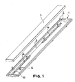
Figure 1 shows an exploded perspective view of the inventive water outlet unit. -
Figure 2 shows a cross-section of the above unit showing the spacers. -
Figure 3 shows a cross-section of the unit offigure 1 showing the passage of water through the plate/frame separation. - In the above figures, the numerical references correspond to the following parts and elements:
- 1. Frame.
- 2. Perimetric support.
- 3. Interior skirting.
- 4. Flanges.
- 5. Plate.
- 6. Spacers.
- 7. Vertical wall.
- 8. Horizontal wall.
- 9. Rib.
- 10. Stud.
- 11. Drill-hole.
- As can be seen in
figures 1 and2 , the water outlet unit for drainage chutes of the invention consists of a frame (1) which presents a perimetric support (2) and an interior skirting (3) terminating in flanges (4). - A plate (5), with dimensions somewhat less than the perimetric support (2) of the frame (1), rests on the flanges (4) and against the interior skirting (3) with the mediation of several spacers (6) which, for these purposes, present a vertical wall (7) and a horizontal wall (8). A rib (9) is provided below the horizontal wall (8) in order to configure a cross-section in "U" which clasps the flange (4), permitting the spacers (6) to be attached to it.
- Optionally, the rib (9) of the spacer (6) can present a stud (10) intended for being introduced into a drill-hole (11) provided in the flange (4), which improves the attachment of the spacer (6) to the frame (1).
- In this way, and as can be seen in
figure 3 , the plate (5) becomes separated both from the interior skirting (3) and from its flange (4) permitting water to pass freely. Although it might seem that the separation between the plate (5) and the frame (1) is too narrow to ensure a high flow of water, this is not the case due to the large perimeter of the device. The change of direction that the flow of water can undergo does not introduce any appreciable restriction on the rate. - There are a series of variants that will be evident to an expert on the subject which, adapting the embodiment of the design and the means of production, respect the essence of the invention. So, advantageously, the plate (5) will be made in toughened glass though it can equally be manufactured in stone, ceramic or another suitable material. Likewise, the frame (1) will advantageously be carried out in folded stainless steel sheet though it can also be done in injected plastic or any other appropriate material.
Claims (2)
- Water outlet unit for drainage chutes characterised by comprising a frame (1) which presents a perimetric support (2) with an interior skirting (3) which terminates in a flange (4), and a plate (5) with dimensions somewhat less than the perimetric support (2) which rests on the flanges (4) and against the interior skirting (3) with the mediation of several spacers (6) which, for these purposes, present a vertical wall (7) and a horizontal wall (8), incorporating a rib (9) which, together with the horizontal wall (8) configures a cross-section in "U" which clasps the flange (4).
- Water outlet unit for drainage chutes according to claim 1, characterised in that the rib (9) of the spacer (6) presents a stud (10) intended to be introduced into a drill-hole (11) provided for these purpose in the flange (4).
Priority Applications (1)
| Application Number | Priority Date | Filing Date | Title |
|---|---|---|---|
| PL12000972T PL2492407T3 (en) | 2011-02-15 | 2012-02-15 | Drainage channel |
Applications Claiming Priority (1)
| Application Number | Priority Date | Filing Date | Title |
|---|---|---|---|
| ES201130156U ES1074769Y (en) | 2011-02-15 | 2011-02-15 | WATER OUTLET ASSEMBLY FOR DRAINAGE CHANNELS |
Related Parent Applications (1)
| Application Number | Title | Priority Date | Filing Date |
|---|---|---|---|
| ES201130156U Previously-Filed-Application | 2011-02-15 |
Publications (2)
| Publication Number | Publication Date |
|---|---|
| EP2492407A1 true EP2492407A1 (en) | 2012-08-29 |
| EP2492407B1 EP2492407B1 (en) | 2013-10-16 |
Family
ID=44063815
Family Applications (1)
| Application Number | Title | Priority Date | Filing Date |
|---|---|---|---|
| EP12000972.5A Active EP2492407B1 (en) | 2011-02-15 | 2012-02-15 | Drainage channel |
Country Status (5)
| Country | Link |
|---|---|
| EP (1) | EP2492407B1 (en) |
| ES (2) | ES1074769Y (en) |
| PL (1) | PL2492407T3 (en) |
| PT (1) | PT2492407E (en) |
| RU (1) | RU2535561C2 (en) |
Citations (5)
| Publication number | Priority date | Publication date | Assignee | Title |
|---|---|---|---|---|
| DE8804073U1 (en) * | 1988-03-25 | 1989-07-20 | Broermann, geb. Muckermann, Rita, 4783 Anröchte | Drainage channel |
| DE19540068A1 (en) * | 1995-10-27 | 1997-04-30 | Finbau Finnentroper Bauelement | Mesh grating, especially for laying in openings in concrete of constructed roads |
| EP1191148A1 (en) * | 2000-09-23 | 2002-03-27 | Wilhelm Wiehe | Frame for mounting a cover and assembly device |
| WO2004072392A1 (en) * | 2003-02-17 | 2004-08-26 | Aco Severin Ahlmann Gmbh & Co. Kg | Street grid for surface drainage |
| DE202006014959U1 (en) * | 2006-09-27 | 2008-02-14 | Viega Gmbh & Co. Kg | Floor drain, especially in the form of a shower channel |
Family Cites Families (2)
| Publication number | Priority date | Publication date | Assignee | Title |
|---|---|---|---|---|
| JPS6452932A (en) * | 1988-08-03 | 1989-03-01 | Daiichi Kizai Kk | Drainage method of road-surface flowing water |
| DE8910414U1 (en) * | 1989-08-31 | 1989-10-26 | Passavant-Werke AG, 6209 Aarbergen | Channel for the drainage of surface water |
-
2011
- 2011-02-15 ES ES201130156U patent/ES1074769Y/en not_active Expired - Fee Related
-
2012
- 2012-02-15 EP EP12000972.5A patent/EP2492407B1/en active Active
- 2012-02-15 PL PL12000972T patent/PL2492407T3/en unknown
- 2012-02-15 RU RU2012105143/13A patent/RU2535561C2/en active
- 2012-02-15 ES ES12000972.5T patent/ES2442665T3/en active Active
- 2012-03-21 PT PT120009725T patent/PT2492407E/en unknown
Patent Citations (5)
| Publication number | Priority date | Publication date | Assignee | Title |
|---|---|---|---|---|
| DE8804073U1 (en) * | 1988-03-25 | 1989-07-20 | Broermann, geb. Muckermann, Rita, 4783 Anröchte | Drainage channel |
| DE19540068A1 (en) * | 1995-10-27 | 1997-04-30 | Finbau Finnentroper Bauelement | Mesh grating, especially for laying in openings in concrete of constructed roads |
| EP1191148A1 (en) * | 2000-09-23 | 2002-03-27 | Wilhelm Wiehe | Frame for mounting a cover and assembly device |
| WO2004072392A1 (en) * | 2003-02-17 | 2004-08-26 | Aco Severin Ahlmann Gmbh & Co. Kg | Street grid for surface drainage |
| DE202006014959U1 (en) * | 2006-09-27 | 2008-02-14 | Viega Gmbh & Co. Kg | Floor drain, especially in the form of a shower channel |
Also Published As
| Publication number | Publication date |
|---|---|
| EP2492407B1 (en) | 2013-10-16 |
| PT2492407E (en) | 2014-01-23 |
| PL2492407T3 (en) | 2014-03-31 |
| ES1074769U (en) | 2011-06-09 |
| ES1074769Y (en) | 2011-09-27 |
| RU2012105143A (en) | 2013-08-20 |
| ES2442665T3 (en) | 2014-02-12 |
| RU2535561C2 (en) | 2014-12-20 |
Similar Documents
| Publication | Publication Date | Title |
|---|---|---|
| US783556A (en) | Catch-basin top. | |
| US20160040409A1 (en) | Mesh covering for drain | |
| KR20140145494A (en) | Air cleaner using plants | |
| CN106381915A (en) | Winding preventing floor drain | |
| EP2492407A1 (en) | Drainage channel | |
| US20150345117A1 (en) | Faucet Water Output Structure | |
| KR200444012Y1 (en) | Drain trap | |
| KR100887004B1 (en) | Drain trap | |
| MX2019008723A (en) | Vortex-type grit chamber. | |
| KR100939452B1 (en) | Diffuser of air conditioning system | |
| CN103981939B (en) | filter | |
| CN203755394U (en) | Water discharging device having cleaning function | |
| EP3120699B1 (en) | Undergravel filter for an aquarium | |
| CN211114031U (en) | Anti-blocking and deodorizing gypsum drainage device | |
| JP7040879B2 (en) | Wastewater piping system and air valve | |
| CN202595890U (en) | Mouse-proof and odor-proof water draining device | |
| BE1018997A5 (en) | VENTILATION MOUTH FOR A VENTILATION DEVICE. | |
| CN205637058U (en) | Bulk moulding compound floor drain | |
| BE1016650A3 (en) | IMPROVED DEVICE FOR DIVIDING AND / OR DRAINING VENTILATION AIR IN A BUILDING. | |
| JP3174403U (en) | Road side structure drainage structure drainage cover pipe L-shaped ventilation movable check cover plate | |
| DE202014010049U1 (en) | Exhaust air purification device for stable installations | |
| KR20150000276A (en) | Filter structure for Heating Ventilation Air Conditioning | |
| CN208267059U (en) | A kind of floor drain | |
| KR101950600B1 (en) | Drainage system that removes foreign matter and adjusts flow rate | |
| CN202347601U (en) | Hand sink structure |
Legal Events
| Date | Code | Title | Description |
|---|---|---|---|
| PUAI | Public reference made under article 153(3) epc to a published international application that has entered the european phase |
Free format text: ORIGINAL CODE: 0009012 |
|
| AK | Designated contracting states |
Kind code of ref document: A1 Designated state(s): AL AT BE BG CH CY CZ DE DK EE ES FI FR GB GR HR HU IE IS IT LI LT LU LV MC MK MT NL NO PL PT RO RS SE SI SK SM TR |
|
| AX | Request for extension of the european patent |
Extension state: BA ME |
|
| 17P | Request for examination filed |
Effective date: 20121116 |
|
| GRAP | Despatch of communication of intention to grant a patent |
Free format text: ORIGINAL CODE: EPIDOSNIGR1 |
|
| GRAS | Grant fee paid |
Free format text: ORIGINAL CODE: EPIDOSNIGR3 |
|
| GRAA | (expected) grant |
Free format text: ORIGINAL CODE: 0009210 |
|
| AK | Designated contracting states |
Kind code of ref document: B1 Designated state(s): AL AT BE BG CH CY CZ DE DK EE ES FI FR GB GR HR HU IE IS IT LI LT LU LV MC MK MT NL NO PL PT RO RS SE SI SK SM TR |
|
| REG | Reference to a national code |
Ref country code: GB Ref legal event code: FG4D |
|
| REG | Reference to a national code |
Ref country code: CH Ref legal event code: EP |
|
| REG | Reference to a national code |
Ref country code: IE Ref legal event code: FG4D |
|
| REG | Reference to a national code |
Ref country code: AT Ref legal event code: REF Ref document number: 636601 Country of ref document: AT Kind code of ref document: T Effective date: 20131115 |
|
| REG | Reference to a national code |
Ref country code: DE Ref legal event code: R096 Ref document number: 602012000375 Country of ref document: DE Effective date: 20131212 |
|
| REG | Reference to a national code |
Ref country code: PT Ref legal event code: SC4A Free format text: AVAILABILITY OF NATIONAL TRANSLATION Effective date: 20140115 |
|
| REG | Reference to a national code |
Ref country code: NL Ref legal event code: T3 |
|
| REG | Reference to a national code |
Ref country code: NL Ref legal event code: T3 |
|
| REG | Reference to a national code |
Ref country code: ES Ref legal event code: FG2A Ref document number: 2442665 Country of ref document: ES Kind code of ref document: T3 Effective date: 20140212 |
|
| REG | Reference to a national code |
Ref country code: AT Ref legal event code: MK05 Ref document number: 636601 Country of ref document: AT Kind code of ref document: T Effective date: 20131016 |
|
| REG | Reference to a national code |
Ref country code: LT Ref legal event code: MG4D |
|
| PG25 | Lapsed in a contracting state [announced via postgrant information from national office to epo] |
Ref country code: IS Free format text: LAPSE BECAUSE OF FAILURE TO SUBMIT A TRANSLATION OF THE DESCRIPTION OR TO PAY THE FEE WITHIN THE PRESCRIBED TIME-LIMIT Effective date: 20140216 Ref country code: FI Free format text: LAPSE BECAUSE OF FAILURE TO SUBMIT A TRANSLATION OF THE DESCRIPTION OR TO PAY THE FEE WITHIN THE PRESCRIBED TIME-LIMIT Effective date: 20131016 Ref country code: SE Free format text: LAPSE BECAUSE OF FAILURE TO SUBMIT A TRANSLATION OF THE DESCRIPTION OR TO PAY THE FEE WITHIN THE PRESCRIBED TIME-LIMIT Effective date: 20131016 Ref country code: LT Free format text: LAPSE BECAUSE OF FAILURE TO SUBMIT A TRANSLATION OF THE DESCRIPTION OR TO PAY THE FEE WITHIN THE PRESCRIBED TIME-LIMIT Effective date: 20131016 Ref country code: HR Free format text: LAPSE BECAUSE OF FAILURE TO SUBMIT A TRANSLATION OF THE DESCRIPTION OR TO PAY THE FEE WITHIN THE PRESCRIBED TIME-LIMIT Effective date: 20131016 Ref country code: NO Free format text: LAPSE BECAUSE OF FAILURE TO SUBMIT A TRANSLATION OF THE DESCRIPTION OR TO PAY THE FEE WITHIN THE PRESCRIBED TIME-LIMIT Effective date: 20140116 |
|
| PG25 | Lapsed in a contracting state [announced via postgrant information from national office to epo] |
Ref country code: CY Free format text: LAPSE BECAUSE OF FAILURE TO SUBMIT A TRANSLATION OF THE DESCRIPTION OR TO PAY THE FEE WITHIN THE PRESCRIBED TIME-LIMIT Effective date: 20131016 Ref country code: RS Free format text: LAPSE BECAUSE OF FAILURE TO SUBMIT A TRANSLATION OF THE DESCRIPTION OR TO PAY THE FEE WITHIN THE PRESCRIBED TIME-LIMIT Effective date: 20131016 Ref country code: AT Free format text: LAPSE BECAUSE OF FAILURE TO SUBMIT A TRANSLATION OF THE DESCRIPTION OR TO PAY THE FEE WITHIN THE PRESCRIBED TIME-LIMIT Effective date: 20131016 Ref country code: LV Free format text: LAPSE BECAUSE OF FAILURE TO SUBMIT A TRANSLATION OF THE DESCRIPTION OR TO PAY THE FEE WITHIN THE PRESCRIBED TIME-LIMIT Effective date: 20131016 |
|
| REG | Reference to a national code |
Ref country code: DE Ref legal event code: R097 Ref document number: 602012000375 Country of ref document: DE |
|
| PG25 | Lapsed in a contracting state [announced via postgrant information from national office to epo] |
Ref country code: EE Free format text: LAPSE BECAUSE OF FAILURE TO SUBMIT A TRANSLATION OF THE DESCRIPTION OR TO PAY THE FEE WITHIN THE PRESCRIBED TIME-LIMIT Effective date: 20131016 |
|
| PLBE | No opposition filed within time limit |
Free format text: ORIGINAL CODE: 0009261 |
|
| STAA | Information on the status of an ep patent application or granted ep patent |
Free format text: STATUS: NO OPPOSITION FILED WITHIN TIME LIMIT |
|
| PG25 | Lapsed in a contracting state [announced via postgrant information from national office to epo] |
Ref country code: RO Free format text: LAPSE BECAUSE OF FAILURE TO SUBMIT A TRANSLATION OF THE DESCRIPTION OR TO PAY THE FEE WITHIN THE PRESCRIBED TIME-LIMIT Effective date: 20131016 Ref country code: SK Free format text: LAPSE BECAUSE OF FAILURE TO SUBMIT A TRANSLATION OF THE DESCRIPTION OR TO PAY THE FEE WITHIN THE PRESCRIBED TIME-LIMIT Effective date: 20131016 Ref country code: CZ Free format text: LAPSE BECAUSE OF FAILURE TO SUBMIT A TRANSLATION OF THE DESCRIPTION OR TO PAY THE FEE WITHIN THE PRESCRIBED TIME-LIMIT Effective date: 20131016 |
|
| 26N | No opposition filed |
Effective date: 20140717 |
|
| PG25 | Lapsed in a contracting state [announced via postgrant information from national office to epo] |
Ref country code: DK Free format text: LAPSE BECAUSE OF FAILURE TO SUBMIT A TRANSLATION OF THE DESCRIPTION OR TO PAY THE FEE WITHIN THE PRESCRIBED TIME-LIMIT Effective date: 20131016 Ref country code: MC Free format text: LAPSE BECAUSE OF FAILURE TO SUBMIT A TRANSLATION OF THE DESCRIPTION OR TO PAY THE FEE WITHIN THE PRESCRIBED TIME-LIMIT Effective date: 20131016 Ref country code: LU Free format text: LAPSE BECAUSE OF FAILURE TO SUBMIT A TRANSLATION OF THE DESCRIPTION OR TO PAY THE FEE WITHIN THE PRESCRIBED TIME-LIMIT Effective date: 20140215 |
|
| REG | Reference to a national code |
Ref country code: DE Ref legal event code: R097 Ref document number: 602012000375 Country of ref document: DE Effective date: 20140717 |
|
| REG | Reference to a national code |
Ref country code: IE Ref legal event code: MM4A |
|
| PG25 | Lapsed in a contracting state [announced via postgrant information from national office to epo] |
Ref country code: IE Free format text: LAPSE BECAUSE OF NON-PAYMENT OF DUE FEES Effective date: 20140215 |
|
| REG | Reference to a national code |
Ref country code: FR Ref legal event code: PLFP Year of fee payment: 4 |
|
| PG25 | Lapsed in a contracting state [announced via postgrant information from national office to epo] |
Ref country code: SI Free format text: LAPSE BECAUSE OF FAILURE TO SUBMIT A TRANSLATION OF THE DESCRIPTION OR TO PAY THE FEE WITHIN THE PRESCRIBED TIME-LIMIT Effective date: 20131016 |
|
| REG | Reference to a national code |
Ref country code: CH Ref legal event code: PL |
|
| PG25 | Lapsed in a contracting state [announced via postgrant information from national office to epo] |
Ref country code: LI Free format text: LAPSE BECAUSE OF NON-PAYMENT OF DUE FEES Effective date: 20150228 Ref country code: CH Free format text: LAPSE BECAUSE OF NON-PAYMENT OF DUE FEES Effective date: 20150228 |
|
| REG | Reference to a national code |
Ref country code: FR Ref legal event code: PLFP Year of fee payment: 5 |
|
| PG25 | Lapsed in a contracting state [announced via postgrant information from national office to epo] |
Ref country code: MT Free format text: LAPSE BECAUSE OF FAILURE TO SUBMIT A TRANSLATION OF THE DESCRIPTION OR TO PAY THE FEE WITHIN THE PRESCRIBED TIME-LIMIT Effective date: 20131016 |
|
| PG25 | Lapsed in a contracting state [announced via postgrant information from national office to epo] |
Ref country code: SM Free format text: LAPSE BECAUSE OF FAILURE TO SUBMIT A TRANSLATION OF THE DESCRIPTION OR TO PAY THE FEE WITHIN THE PRESCRIBED TIME-LIMIT Effective date: 20131016 |
|
| PG25 | Lapsed in a contracting state [announced via postgrant information from national office to epo] |
Ref country code: BG Free format text: LAPSE BECAUSE OF FAILURE TO SUBMIT A TRANSLATION OF THE DESCRIPTION OR TO PAY THE FEE WITHIN THE PRESCRIBED TIME-LIMIT Effective date: 20131016 Ref country code: GR Free format text: LAPSE BECAUSE OF FAILURE TO SUBMIT A TRANSLATION OF THE DESCRIPTION OR TO PAY THE FEE WITHIN THE PRESCRIBED TIME-LIMIT Effective date: 20140117 |
|
| PG25 | Lapsed in a contracting state [announced via postgrant information from national office to epo] |
Ref country code: HU Free format text: LAPSE BECAUSE OF FAILURE TO SUBMIT A TRANSLATION OF THE DESCRIPTION OR TO PAY THE FEE WITHIN THE PRESCRIBED TIME-LIMIT; INVALID AB INITIO Effective date: 20120215 Ref country code: TR Free format text: LAPSE BECAUSE OF FAILURE TO SUBMIT A TRANSLATION OF THE DESCRIPTION OR TO PAY THE FEE WITHIN THE PRESCRIBED TIME-LIMIT Effective date: 20131016 |
|
| REG | Reference to a national code |
Ref country code: FR Ref legal event code: PLFP Year of fee payment: 6 |
|
| REG | Reference to a national code |
Ref country code: FR Ref legal event code: PLFP Year of fee payment: 7 |
|
| PGFP | Annual fee paid to national office [announced via postgrant information from national office to epo] |
Ref country code: GB Payment date: 20180212 Year of fee payment: 7 |
|
| PG25 | Lapsed in a contracting state [announced via postgrant information from national office to epo] |
Ref country code: MK Free format text: LAPSE BECAUSE OF FAILURE TO SUBMIT A TRANSLATION OF THE DESCRIPTION OR TO PAY THE FEE WITHIN THE PRESCRIBED TIME-LIMIT Effective date: 20131016 |
|
| PG25 | Lapsed in a contracting state [announced via postgrant information from national office to epo] |
Ref country code: AL Free format text: LAPSE BECAUSE OF FAILURE TO SUBMIT A TRANSLATION OF THE DESCRIPTION OR TO PAY THE FEE WITHIN THE PRESCRIBED TIME-LIMIT Effective date: 20131016 |
|
| GBPC | Gb: european patent ceased through non-payment of renewal fee |
Effective date: 20190215 |
|
| PG25 | Lapsed in a contracting state [announced via postgrant information from national office to epo] |
Ref country code: GB Free format text: LAPSE BECAUSE OF NON-PAYMENT OF DUE FEES Effective date: 20190215 |
|
| REG | Reference to a national code |
Ref country code: DE Ref legal event code: R082 Ref document number: 602012000375 Country of ref document: DE Representative=s name: BRAEUNING & SCHUBERT PATENTANWAELTE GBR, DE Ref country code: DE Ref legal event code: R082 Ref document number: 602012000375 Country of ref document: DE Representative=s name: BRAEUNING & SCHUBERT PATENTANWAELTE, DE Ref country code: DE Ref legal event code: R082 Ref document number: 602012000375 Country of ref document: DE Representative=s name: SCHUBERT, KLEMENS, DIPL.-CHEM. DR.RER.NAT., DE |
|
| P01 | Opt-out of the competence of the unified patent court (upc) registered |
Effective date: 20230523 |
|
| REG | Reference to a national code |
Ref country code: DE Ref legal event code: R082 Ref document number: 602012000375 Country of ref document: DE Representative=s name: BRAEUNING & SCHUBERT PATENTANWAELTE GBR, DE Ref country code: DE Ref legal event code: R082 Ref document number: 602012000375 Country of ref document: DE Representative=s name: BRAEUNING & SCHUBERT PATENTANWAELTE, DE |
|
| PGFP | Annual fee paid to national office [announced via postgrant information from national office to epo] |
Ref country code: FR Payment date: 20240208 Year of fee payment: 13 |
|
| REG | Reference to a national code |
Ref country code: ES Ref legal event code: PC2A Owner name: ALIAXIS IBERIA, S.A.U. Effective date: 20240715 |
|
| PGFP | Annual fee paid to national office [announced via postgrant information from national office to epo] |
Ref country code: PT Payment date: 20250116 Year of fee payment: 14 Ref country code: DE Payment date: 20250227 Year of fee payment: 14 |
|
| PGFP | Annual fee paid to national office [announced via postgrant information from national office to epo] |
Ref country code: ES Payment date: 20250306 Year of fee payment: 14 |
|
| PGFP | Annual fee paid to national office [announced via postgrant information from national office to epo] |
Ref country code: BE Payment date: 20250227 Year of fee payment: 14 |
|
| PGFP | Annual fee paid to national office [announced via postgrant information from national office to epo] |
Ref country code: PL Payment date: 20250117 Year of fee payment: 14 |
|
| PGFP | Annual fee paid to national office [announced via postgrant information from national office to epo] |
Ref country code: IT Payment date: 20250220 Year of fee payment: 14 |
|
| PG25 | Lapsed in a contracting state [announced via postgrant information from national office to epo] |
Ref country code: FR Free format text: LAPSE BECAUSE OF NON-PAYMENT OF DUE FEES Effective date: 20250228 |
|
| PGFP | Annual fee paid to national office [announced via postgrant information from national office to epo] |
Ref country code: NL Payment date: 20260226 Year of fee payment: 15 |