EP2492191A1 - Panel member, aircraft main wing, and method for forming panel member - Google Patents
Panel member, aircraft main wing, and method for forming panel member Download PDFInfo
- Publication number
- EP2492191A1 EP2492191A1 EP12151367A EP12151367A EP2492191A1 EP 2492191 A1 EP2492191 A1 EP 2492191A1 EP 12151367 A EP12151367 A EP 12151367A EP 12151367 A EP12151367 A EP 12151367A EP 2492191 A1 EP2492191 A1 EP 2492191A1
- Authority
- EP
- European Patent Office
- Prior art keywords
- thickness
- panel member
- areas
- wing
- panel
- Prior art date
- Legal status (The legal status is an assumption and is not a legal conclusion. Google has not performed a legal analysis and makes no representation as to the accuracy of the status listed.)
- Granted
Links
Images


Classifications
-
- B—PERFORMING OPERATIONS; TRANSPORTING
- B64—AIRCRAFT; AVIATION; COSMONAUTICS
- B64C—AEROPLANES; HELICOPTERS
- B64C3/00—Wings
- B64C3/26—Construction, shape, or attachment of separate skins, e.g. panels
-
- Y—GENERAL TAGGING OF NEW TECHNOLOGICAL DEVELOPMENTS; GENERAL TAGGING OF CROSS-SECTIONAL TECHNOLOGIES SPANNING OVER SEVERAL SECTIONS OF THE IPC; TECHNICAL SUBJECTS COVERED BY FORMER USPC CROSS-REFERENCE ART COLLECTIONS [XRACs] AND DIGESTS
- Y10—TECHNICAL SUBJECTS COVERED BY FORMER USPC
- Y10T—TECHNICAL SUBJECTS COVERED BY FORMER US CLASSIFICATION
- Y10T29/00—Metal working
- Y10T29/49—Method of mechanical manufacture
- Y10T29/49616—Structural member making
- Y10T29/49622—Vehicular structural member making
-
- Y—GENERAL TAGGING OF NEW TECHNOLOGICAL DEVELOPMENTS; GENERAL TAGGING OF CROSS-SECTIONAL TECHNOLOGIES SPANNING OVER SEVERAL SECTIONS OF THE IPC; TECHNICAL SUBJECTS COVERED BY FORMER USPC CROSS-REFERENCE ART COLLECTIONS [XRACs] AND DIGESTS
- Y10—TECHNICAL SUBJECTS COVERED BY FORMER USPC
- Y10T—TECHNICAL SUBJECTS COVERED BY FORMER US CLASSIFICATION
- Y10T428/00—Stock material or miscellaneous articles
- Y10T428/12—All metal or with adjacent metals
- Y10T428/12389—All metal or with adjacent metals having variation in thickness
-
- Y—GENERAL TAGGING OF NEW TECHNOLOGICAL DEVELOPMENTS; GENERAL TAGGING OF CROSS-SECTIONAL TECHNOLOGIES SPANNING OVER SEVERAL SECTIONS OF THE IPC; TECHNICAL SUBJECTS COVERED BY FORMER USPC CROSS-REFERENCE ART COLLECTIONS [XRACs] AND DIGESTS
- Y10—TECHNICAL SUBJECTS COVERED BY FORMER USPC
- Y10T—TECHNICAL SUBJECTS COVERED BY FORMER US CLASSIFICATION
- Y10T428/00—Stock material or miscellaneous articles
- Y10T428/24—Structurally defined web or sheet [e.g., overall dimension, etc.]
- Y10T428/24479—Structurally defined web or sheet [e.g., overall dimension, etc.] including variation in thickness
Definitions
- the present invention relates to a panel member, an aircraft main wing, and a method for forming the panel member.
- a wing panel For an aircraft main wing, the outer surface thereof is formed by a panel-form member (hereinafter, referred to as a wing panel).
- This wing panel is configured so that the thickness thereof is set according to the portion of the wing. That is, in the base end portion on the airframe side of main wing, and in the portion around the engine-mounting position, the thickness of wing panel is set so as to be large because high strength is required in these portions. In contrast, in the tip end portion of wing or the like portions, the thickness of wing panel is set so as to be small. Thus, the thickness of wing panel is prevented from being increased than necessary while a necessary strength is ensured depending on the respective portions, whereby the weight of wing panel is restrained,
- Some wing panels are formed by being machined out of a metallic base material (for example, refer to Takeshi Yamada et al. "Development of Shot Peen Forming Technology of Main Wing Integral Skin of Continental Business Jet” Mitsubishi Heavy Industries Technical Review, Vol.39, No.1 (2002), p.36 ).
- the position of the cutting tool of a cutting machine with respect to the metallic base material is changed stepwise.
- the change amount of the thickness must be set to a dimension equal to or larger than the machining tolerance.
- the machining tolerance is, for example, ⁇ 0.1 mm
- the thickness is preferably increased or decreased stepwise for each dimension equal to or larger than the machining tolerance, for example, for each dimension equal to or larger than 0.2 mm (this increasing/decreasing amount is referred to as a step amount as appropriate). That is, in the case where the design value of thickness in a certain portion P1 of a wing panel 1 is 6.0 mm as shown in FIGS.
- the design value of thickness in the portion P2 is 6.1 mm
- the thickness increases from the portion P1 to the portion P2 in design, actually, in some cases, the thickness does not change, or inversely the thickness decreases from the portion P1 to the portion P2. Even in such a case, no problem occurs in terms of strength as long as the thicknesses of the portions P1 and P2 are within the machining tolerance. However, a hindrance may occur in the manufacturing process.
- the wing panel machined out of a metallic base material by cutting machine is inspected at least visually. If a flaw or the like induced while machining is present on the wing panel, the surroundings of the flaw must be sanded to correct the flaw to the predefined standard or higher grade.
- the step amount of thickness is small, the step existing in the portion in which the thickness changes becomes a minor step, and therefore, at the inspection time, it is sometimes impossible to distinguish between a normal step and a flaw. For this reason, correction is sometimes made as the result of mistaking the normal step for a flaw, which leads to an increase in the manufacturing cost.
- the thickness design value of 6.4 mm is an excess value by 0.3 mm.
- the present invention has been made to solve the above-described technical problems, and accordingly an object thereof is to provide a panel member capable of restraining an increase in weight of a wing panel while restraining wasteful work in the manufacturing process, an aircraft main wing formed by the said panel member, and a method for forming a panel member.
- the present invention provides a panel member forming the outer surface of an aircraft, wherein a portion of the panel member in which the thickness thereof changes gradually is divided into a plurality of areas each having a certain thickness; the thicknesses of the adjacent areas are different from each other; and in the boundary portion between the adjacent areas, there is formed a ridge having a height larger than the dimensional difference in thickness between the areas on both sides of the boundary portion.
- Such a ridge is preferably formed so as to have a height larger than the machining tolerance of the panel member.
- the panel member is formed by being machined out of a metallic base material.
- Such a panel member can also be used in forming a portion other than the outer surface of main wing.
- the present invention provides an aircraft main wing wherein the outer surface of the wing is formed by the panel member described above.
- the present invention provides a method for forming a panel member, in which the panel member is machined out of a metallic base material, wherein a portion in which the thickness changes gradually is divided into a plurality of areas; each of the areas is formed so as to have a certain thickness; and in the boundary portion between the adjacent areas, there is formed a ridge having a height larger than the dimensional difference in thickness between the areas on both sides of the boundary portion.
- the present invention is not limited to the case where the panel member and stringers (reinforcing ribs) are integrally machined out of a thick plate, and can be applied to a so-called built-up panel in which the stringers are fastened to the panel member with fasteners as far as the panel member is machined out of a thick plate.
- the boundary portion between the adjacent areas there is formed the ridge having a height larger than the dimensional difference in thickness between the areas on both sides of the boundary portion.
- the boundary portion between the adjacent areas each having a different thickness can be visually confirmed easily. Thereby, only a portion in which a flaw occurs in each area can be corrected, so that wasteful work in the manufacturing process can be restrained.
- the boundary portion between the adjacent areas can also be formed so as to have a thickness equal to or smaller than the machining tolerance, and thereby the increase in weight of the wing panel can be restrained.
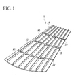
- FIG. 1 is a perspective view for explaining a wing panel 10 in accordance with this embodiment.
- the wing panel 10 forms the outer surface of an aircraft main wing.
- the wing panel 10 is formed so as to have the necessary minimum thickness or a larger thickness depending on a portion of a main wing.
- the wing panel 10 is formed by being machined out of a metallic base material.
- the thickness of the wing panel 10 is changed by dividing the wing panel 10 into a plurality of areas A1, A2, ... and by gradually increasing or decreasing the thicknesses t1, t2, ... of the areas A1, A2, ... , respectively.
- the change amounts of thicknesses of the adjacent areas (for example, area A1 and area A2, area A2 and area A3), that is, the difference between thickness t1 and thickness t2, the difference between thickness t2 and thickness t3, and so on are set so as to be a specified value s or larger.
- the specified value s can be set optionally regardless of the machining tolerance set at the design time. That is, the specified value s can be made a dimension equal to or larger than the machining tolerance.
- ridges 20 are formed so as to be continuous.
- This ridge 20 has a height h equal to or larger than the machining tolerance and a width w.
- both of the height h and the width w can be set at about 1 mm.
- the worker who handles the wing panel 10 can visually confirm the step portions of the areas A1, A2, ... easily. Thereby, if a flaw or the like is found in the areas A1, A2, ... , corrective actions can be properly taken on the actually existing flaw without mistaking the flaw for the step portion of the areas A1, A2, ....
- a configuration can be provided in which no hindrance occurs even if the change amounts of thicknesses of the areas A1, A2, ... (the difference between thickness t1 and thickness t2, the difference between thickness t2 and thickness t3) are equal to or smaller than the machining tolerance.
- each of the thicknesses of the areas A1, A2, ... can be made the necessary minimum thickness, and the wing panel 10 can be formed without having a wasteful thickness.
- the weight of the wing panel 10 is not increased, so that the weight thereof can be reduced as compared with the conventional configuration.
- the ridges 20 can be caused to function as a reinforcing element for the wing panel 10. Thereby, the thicknesses of the areas A1 A2, ... are decreased further, so that the weight of the wing panel 10 can also be reduced.
- the ridge is formed into a rectangular shape in cross section.
- the ridge shape is not limited to this shape, and as shown in FIGS. 3A and 3B , the ridge can be formed into a triangular shape or an inverse U shape in cross section.
Abstract
Description
- The present invention relates to a panel member, an aircraft main wing, and a method for forming the panel member.
- For an aircraft main wing, the outer surface thereof is formed by a panel-form member (hereinafter, referred to as a wing panel). This wing panel is configured so that the thickness thereof is set according to the portion of the wing. That is, in the base end portion on the airframe side of main wing, and in the portion around the engine-mounting position, the thickness of wing panel is set so as to be large because high strength is required in these portions. In contrast, in the tip end portion of wing or the like portions, the thickness of wing panel is set so as to be small. Thus, the thickness of wing panel is prevented from being increased than necessary while a necessary strength is ensured depending on the respective portions, whereby the weight of wing panel is restrained,
- Some wing panels are formed by being machined out of a metallic base material (for example, refer to Takeshi Yamada et al. "Development of Shot Peen Forming Technology of Main Wing Integral Skin of Continental Business Jet" Mitsubishi Heavy Industries Technical Review, Vol.39, No.1 (2002), p.36).
- For such a wing panel, to make the thickness thereof different according to the portions, generally, in a portion in which the thickness changes, the position of the cutting tool of a cutting machine with respect to the metallic base material is changed stepwise.
- Unfortunately, in the case where the wing panel is machined out of a material, a machining tolerance exists depending on the capability or the like of the cutting machine. In the portion in which the thickness changes, the change amount of the thickness must be set to a dimension equal to or larger than the machining tolerance. In the case where the machining tolerance is, for example, ±0.1 mm, the thickness is preferably increased or decreased stepwise for each dimension equal to or larger than the machining tolerance, for example, for each dimension equal to or larger than 0.2 mm (this increasing/decreasing amount is referred to as a step amount as appropriate). That is, in the case where the design value of thickness in a certain portion P1 of a wing panel 1 is 6.0 mm as shown in
FIGS. 4 and5 , the actual dimension after machining of the portion P1 is 6.0 ± 0. 1 mm = 5.9 to 6.1 mm. In the case where the step amount of thickness in a portion P2 adjacent to the portion P1 is 0.1 mm, which is equal to the machining tolerance, the design value of thickness in the portion P2 is 6.1 mm, and the actual dimension after machining is 6.1 ± 0.1 mm = 6.0 to 6.2 mm. - In such a case, as shown in
FIG. 5 , although the thickness increases from the portion P1 to the portion P2 in design, actually, in some cases, the thickness does not change, or inversely the thickness decreases from the portion P1 to the portion P2. Even in such a case, no problem occurs in terms of strength as long as the thicknesses of the portions P1 and P2 are within the machining tolerance. However, a hindrance may occur in the manufacturing process. - At the site of manufacturing process, the wing panel machined out of a metallic base material by cutting machine is inspected at least visually. If a flaw or the like induced while machining is present on the wing panel, the surroundings of the flaw must be sanded to correct the flaw to the predefined standard or higher grade.
- If the step amount of thickness is small, the step existing in the portion in which the thickness changes becomes a minor step, and therefore, at the inspection time, it is sometimes impossible to distinguish between a normal step and a flaw. For this reason, correction is sometimes made as the result of mistaking the normal step for a flaw, which leads to an increase in the manufacturing cost.
- To overcome this problem, conventionally, by setting the step amount of thickness to a dimension larger than the machining tolerance as described above, measures have been taken such that a step formed in the portion in which the thickness changes can be checked visually with ease. Thereby, the correction is prevented from being made as the result of mistaking the normal step for a flaw, and thereby the increase in the manufacturing cost is restrained.
- Unfortunately, if the step amount of thickness is made larger than the machining tolerance, a portion having a thickness larger than necessary is produced, which leads to an increase in weight of the wing panel. For example, in the above-described example, in the case where the step amount of thickness in the portion P2 adjacent to the portion P1 is made 0.4 mm, which is larger than the machining tolerance, the design value of thickness in the portion P2 becomes 6.4 mm, so that the actual dimension after machining becomes 6.4 ± 0.1 mm = 6.3 to 6.5 mm. Therefore, in the boundary portion between the portion P1 and the portion P2, a step of at least 0.1 mm arises. However, in the portion P2, assuming that the above-described thickness of 6.1 mm provides a necessary strength, the thickness design value of 6.4 mm is an excess value by 0.3 mm.
- The present invention has been made to solve the above-described technical problems, and accordingly an object thereof is to provide a panel member capable of restraining an increase in weight of a wing panel while restraining wasteful work in the manufacturing process, an aircraft main wing formed by the said panel member, and a method for forming a panel member.
- To achieve the above object, the present invention provides a panel member forming the outer surface of an aircraft, wherein a portion of the panel member in which the thickness thereof changes gradually is divided into a plurality of areas each having a certain thickness; the thicknesses of the adjacent areas are different from each other; and in the boundary portion between the adjacent areas, there is formed a ridge having a height larger than the dimensional difference in thickness between the areas on both sides of the boundary portion. By this ridge, the boundary portion between the adjacent areas each having a different thickness can be visually confirmed easily.
- Such a ridge is preferably formed so as to have a height larger than the machining tolerance of the panel member.
- Also, the panel member is formed by being machined out of a metallic base material.
- Such a panel member can also be used in forming a portion other than the outer surface of main wing.
- Also, the present invention provides an aircraft main wing wherein the outer surface of the wing is formed by the panel member described above.
- Further, the present invention provides a method for forming a panel member, in which the panel member is machined out of a metallic base material, wherein a portion in which the thickness changes gradually is divided into a plurality of areas; each of the areas is formed so as to have a certain thickness; and in the boundary portion between the adjacent areas, there is formed a ridge having a height larger than the dimensional difference in thickness between the areas on both sides of the boundary portion.
- The present invention is not limited to the case where the panel member and stringers (reinforcing ribs) are integrally machined out of a thick plate, and can be applied to a so-called built-up panel in which the stringers are fastened to the panel member with fasteners as far as the panel member is machined out of a thick plate.
- According to the present invention, in the boundary portion between the adjacent areas, there is formed the ridge having a height larger than the dimensional difference in thickness between the areas on both sides of the boundary portion. By this ridge, the boundary portion between the adjacent areas each having a different thickness can be visually confirmed easily. Thereby, only a portion in which a flaw occurs in each area can be corrected, so that wasteful work in the manufacturing process can be restrained. Also, the boundary portion between the adjacent areas can also be formed so as to have a thickness equal to or smaller than the machining tolerance, and thereby the increase in weight of the wing panel can be restrained.
-
-
FIG. 1 is a perspective view showing a part of a wing panel in accordance with an embodiment of the present invention; -
FIG. 2 is a sectional view of the wing panel shown inFIG. 1 ; -
FIG. 3 is sectional views showing other examples in which the cross-sectional shape of a ridge formed on a wing panel is different; -
FIG. 4 is a perspective view showing a part of a conventional wing panel; and -
FIG. 5 is a sectional view of a conventional wing panel. - The present invention will now be described in detail based on an embodiment shown in the accompanying drawings.
-
FIG. 1 is a perspective view for explaining awing panel 10 in accordance with this embodiment. - As shown in
FIG. 1 , thewing panel 10 forms the outer surface of an aircraft main wing. Thewing panel 10 is formed so as to have the necessary minimum thickness or a larger thickness depending on a portion of a main wing. - The
wing panel 10 is formed by being machined out of a metallic base material. - As shown in
FIGS. 1 and2 , in a portion in which the thickness of thewing panel 10 changes, the thickness of thewing panel 10 is changed by dividing thewing panel 10 into a plurality of areas A1, A2, ... and by gradually increasing or decreasing the thicknesses t1, t2, ... of the areas A1, A2, ... , respectively. - At this time, the change amounts of thicknesses of the adjacent areas (for example, area A1 and area A2, area A2 and area A3), that is, the difference between thickness t1 and thickness t2, the difference between thickness t2 and thickness t3, and so on are set so as to be a specified value s or larger.
- The specified value s can be set optionally regardless of the machining tolerance set at the design time. That is, the specified value s can be made a dimension equal to or larger than the machining tolerance.
- In the boundary portions in which the areas A1, A2, ... adjoin each other,
ridges 20 are formed so as to be continuous. Thisridge 20 has a height h equal to or larger than the machining tolerance and a width w. For example, both of the height h and the width w can be set at about 1 mm. - According to the
wing panel 10, since theridges 20 each having a dimension larger than the machining tolerance are formed in the boundary portions of the areas A1, A2, ... , the worker who handles thewing panel 10 can visually confirm the step portions of the areas A1, A2, ... easily. Thereby, if a flaw or the like is found in the areas A1, A2, ... , corrective actions can be properly taken on the actually existing flaw without mistaking the flaw for the step portion of the areas A1, A2, .... - Also, by doing this, a configuration can be provided in which no hindrance occurs even if the change amounts of thicknesses of the areas A1, A2, ... (the difference between thickness t1 and thickness t2, the difference between thickness t2 and thickness t3) are equal to or smaller than the machining tolerance. Thereby, each of the thicknesses of the areas A1, A2, ... can be made the necessary minimum thickness, and the
wing panel 10 can be formed without having a wasteful thickness. Also, by forming theridges 20 in the necessary minimum dimensions, the weight of thewing panel 10 is not increased, so that the weight thereof can be reduced as compared with the conventional configuration. - Further, the
ridges 20 can be caused to function as a reinforcing element for thewing panel 10. Thereby, the thicknesses of the areas A1 A2, ... are decreased further, so that the weight of thewing panel 10 can also be reduced. - In the above-described embodiment, the ridge is formed into a rectangular shape in cross section. However, the ridge shape is not limited to this shape, and as shown in
FIGS. 3A and 3B , the ridge can be formed into a triangular shape or an inverse U shape in cross section. - Besides, the configurations described in the above-described embodiment can be selected, or can be changed to other configurations as appropriate without departing from the spirit and scope of the present invention.
Claims (5)
- A panel member for forming the outer surface of an aircraft, wherein
a portion of the panel member in which the thickness thereof changes gradually is divided into a plurality of areas each having a certain thickness;
the thicknesses of the adjacent areas are different from each other; and
in a boundary portion between the adjacent areas, there is formed a ridge having a height larger than the dimensional difference in thickness between the areas on both sides of the boundary portion. - The panel member according to claim 1, wherein the ridge is formed so as to have a height larger than the machining tolerance of the panel member.
- The panel member according to claim 1 or 2, wherein the panel member is formed by being machined out of a metallic base material.
- An aircraft main wing wherein the outer surface of the wing is formed by the panel member according to any one of the preceding claims.
- A method for forming the panel member according any one of claims 1 to 3, in which the panel member is machined out of a metallic base material, wherein
a portion in which the thickness changes gradually is divided into a plurality of areas;
each of the areas is formed so as to have a certain thickness; and
in a boundary portion between the adjacent areas, there is formed a ridge having the height larger than the dimensional difference in thickness between the areas on both sides of the boundary portion.
Applications Claiming Priority (1)
| Application Number | Priority Date | Filing Date | Title |
|---|---|---|---|
| JP2011038161A JP5361009B2 (en) | 2011-02-24 | 2011-02-24 | Panel material, aircraft wing, panel material forming method |
Publications (2)
| Publication Number | Publication Date |
|---|---|
| EP2492191A1 true EP2492191A1 (en) | 2012-08-29 |
| EP2492191B1 EP2492191B1 (en) | 2017-01-04 |
Family
ID=45491447
Family Applications (1)
| Application Number | Title | Priority Date | Filing Date |
|---|---|---|---|
| EP12151367.5A Active EP2492191B1 (en) | 2011-02-24 | 2012-01-17 | Panel member, aircraft main wing, and method for forming panel member |
Country Status (4)
| Country | Link |
|---|---|
| US (2) | US20120219818A1 (en) |
| EP (1) | EP2492191B1 (en) |
| JP (1) | JP5361009B2 (en) |
| CA (1) | CA2763175C (en) |
Cited By (1)
| Publication number | Priority date | Publication date | Assignee | Title |
|---|---|---|---|---|
| CN106247155A (en) * | 2015-06-15 | 2016-12-21 | 波音公司 | fractal reinforcement |
Citations (3)
| Publication number | Priority date | Publication date | Assignee | Title |
|---|---|---|---|---|
| EP1127785A2 (en) * | 2000-02-22 | 2001-08-29 | EADS Airbus GmbH | Structural component, in particular for an aircraft and its manufacturing method |
| WO2003082670A1 (en) * | 2002-03-27 | 2003-10-09 | Airbus Uk Limited | Wing skin and method of manufacture thereof |
| US20040035979A1 (en) * | 2002-08-23 | 2004-02-26 | Mccoskey William Robert | Integrally stiffened axial load carrying skin panels for primary aircraft structure and closed loop manufacturing methods for making the same |
Family Cites Families (5)
| Publication number | Priority date | Publication date | Assignee | Title |
|---|---|---|---|---|
| AU2002245115A1 (en) * | 2000-12-12 | 2002-07-24 | Remmele Engineering, Inc. | Monolithic part and process for making the same |
| JP2003191028A (en) * | 2001-12-26 | 2003-07-08 | Mitsubishi Heavy Ind Ltd | Peening method |
| DE10301445B4 (en) * | 2003-01-16 | 2005-11-17 | Airbus Deutschland Gmbh | Lightweight structural component, in particular for aircraft and method for its production |
| US8074694B2 (en) * | 2009-05-28 | 2011-12-13 | The Boeing Company | Stringer transition method |
| ES2387854B1 (en) * | 2010-04-30 | 2013-11-07 | Airbus Operations, S.L. | INTERNAL AIRCRAFT STRUCTURE IN COMPOSITE MATERIAL. |
-
2011
- 2011-02-24 JP JP2011038161A patent/JP5361009B2/en active Active
-
2012
- 2012-01-03 CA CA2763175A patent/CA2763175C/en active Active
- 2012-01-17 EP EP12151367.5A patent/EP2492191B1/en active Active
- 2012-02-22 US US13/402,099 patent/US20120219818A1/en not_active Abandoned
-
2015
- 2015-07-06 US US14/792,103 patent/US10081418B2/en active Active
Patent Citations (3)
| Publication number | Priority date | Publication date | Assignee | Title |
|---|---|---|---|---|
| EP1127785A2 (en) * | 2000-02-22 | 2001-08-29 | EADS Airbus GmbH | Structural component, in particular for an aircraft and its manufacturing method |
| WO2003082670A1 (en) * | 2002-03-27 | 2003-10-09 | Airbus Uk Limited | Wing skin and method of manufacture thereof |
| US20040035979A1 (en) * | 2002-08-23 | 2004-02-26 | Mccoskey William Robert | Integrally stiffened axial load carrying skin panels for primary aircraft structure and closed loop manufacturing methods for making the same |
Non-Patent Citations (1)
| Title |
|---|
| TAKESHI YAMADA ET AL.: "Development of Shot Peen Forming Technology of Main Wing Integral Skin of Continental Business Jet", MITSUBISHI HEAVY INDUSTRIES TECHNICAL REVIEW, vol. 39, no. 1, 2002, pages 36 |
Cited By (1)
| Publication number | Priority date | Publication date | Assignee | Title |
|---|---|---|---|---|
| CN106247155A (en) * | 2015-06-15 | 2016-12-21 | 波音公司 | fractal reinforcement |
Also Published As
| Publication number | Publication date |
|---|---|
| US20150307181A1 (en) | 2015-10-29 |
| JP5361009B2 (en) | 2013-12-04 |
| US20120219818A1 (en) | 2012-08-30 |
| EP2492191B1 (en) | 2017-01-04 |
| CA2763175A1 (en) | 2012-08-24 |
| CA2763175C (en) | 2014-04-15 |
| US10081418B2 (en) | 2018-09-25 |
| JP2012171576A (en) | 2012-09-10 |
Similar Documents
| Publication | Publication Date | Title |
|---|---|---|
| CN101511673B (en) | Panel assembly and method of erecting a panel assembly | |
| EP3069964B1 (en) | Underbody manufacturing method and vehicle underbody | |
| US9333566B2 (en) | Indexable cutting insert for milling | |
| US7963483B2 (en) | Stiffening element carbon-glass layered foot section | |
| EP2583814B1 (en) | Method for manufacturing t-shaped aircraft beams and a curing tool used during same | |
| EP2489590B1 (en) | Wing panel and aircraft main wing | |
| US9381993B2 (en) | Airframe panel for aircraft and aircraft wing | |
| US10081418B2 (en) | Panel member, aircraft main wing, and method for forming panel member | |
| US20140315040A1 (en) | Integrally formed stiffener | |
| EP3603942B1 (en) | Locking hole plug for sealing holes in composite structures | |
| US9145195B2 (en) | Aircraft panel structure and aircraft panel structure manufacturing method for alleviation of stress | |
| US9663231B2 (en) | Seat track | |
| RU2490165C2 (en) | System of joint between lining elements and structural elements that support them | |
| JP5883528B1 (en) | Crack growth control method and crack growth control structure | |
| CN217167005U (en) | Planar workpiece made of metal | |
| US11679457B2 (en) | Assembling device | |
| JP6515654B2 (en) | Lap joint, method of manufacturing the same, and method of designing the same | |
| US10392132B2 (en) | Curved aircraft substructure repair systems and methods | |
| US20200400171A1 (en) | Composite material assembly | |
| US20120107435A1 (en) | Re-usable retainers for co-bonding uncured stringers | |
| CN112839752B (en) | Tool holder and device for cold joining | |
| JP2012171576A5 (en) | ||
| WO2022059047A1 (en) | Composite component and method for producing composite component |
Legal Events
| Date | Code | Title | Description |
|---|---|---|---|
| PUAI | Public reference made under article 153(3) epc to a published international application that has entered the european phase |
Free format text: ORIGINAL CODE: 0009012 |
|
| 17P | Request for examination filed |
Effective date: 20120117 |
|
| AK | Designated contracting states |
Kind code of ref document: A1 Designated state(s): AL AT BE BG CH CY CZ DE DK EE ES FI FR GB GR HR HU IE IS IT LI LT LU LV MC MK MT NL NO PL PT RO RS SE SI SK SM TR |
|
| AX | Request for extension of the european patent |
Extension state: BA ME |
|
| 17Q | First examination report despatched |
Effective date: 20150916 |
|
| GRAP | Despatch of communication of intention to grant a patent |
Free format text: ORIGINAL CODE: EPIDOSNIGR1 |
|
| INTG | Intention to grant announced |
Effective date: 20160812 |
|
| GRAS | Grant fee paid |
Free format text: ORIGINAL CODE: EPIDOSNIGR3 |
|
| GRAA | (expected) grant |
Free format text: ORIGINAL CODE: 0009210 |
|
| AK | Designated contracting states |
Kind code of ref document: B1 Designated state(s): AL AT BE BG CH CY CZ DE DK EE ES FI FR GB GR HR HU IE IS IT LI LT LU LV MC MK MT NL NO PL PT RO RS SE SI SK SM TR |
|
| REG | Reference to a national code |
Ref country code: GB Ref legal event code: FG4D |
|
| REG | Reference to a national code |
Ref country code: CH Ref legal event code: EP |
|
| REG | Reference to a national code |
Ref country code: AT Ref legal event code: REF Ref document number: 858948 Country of ref document: AT Kind code of ref document: T Effective date: 20170115 |
|
| REG | Reference to a national code |
Ref country code: IE Ref legal event code: FG4D |
|
| REG | Reference to a national code |
Ref country code: FR Ref legal event code: PLFP Year of fee payment: 6 |
|
| REG | Reference to a national code |
Ref country code: DE Ref legal event code: R096 Ref document number: 602012027272 Country of ref document: DE |
|
| REG | Reference to a national code |
Ref country code: LT Ref legal event code: MG4D Ref country code: NL Ref legal event code: MP Effective date: 20170104 |
|
| PG25 | Lapsed in a contracting state [announced via postgrant information from national office to epo] |
Ref country code: BE Free format text: LAPSE BECAUSE OF NON-PAYMENT OF DUE FEES Effective date: 20170131 |
|
| REG | Reference to a national code |
Ref country code: AT Ref legal event code: MK05 Ref document number: 858948 Country of ref document: AT Kind code of ref document: T Effective date: 20170104 |
|
| PG25 | Lapsed in a contracting state [announced via postgrant information from national office to epo] |
Ref country code: NL Free format text: LAPSE BECAUSE OF FAILURE TO SUBMIT A TRANSLATION OF THE DESCRIPTION OR TO PAY THE FEE WITHIN THE PRESCRIBED TIME-LIMIT Effective date: 20170104 |
|
| PG25 | Lapsed in a contracting state [announced via postgrant information from national office to epo] |
Ref country code: LT Free format text: LAPSE BECAUSE OF FAILURE TO SUBMIT A TRANSLATION OF THE DESCRIPTION OR TO PAY THE FEE WITHIN THE PRESCRIBED TIME-LIMIT Effective date: 20170104 Ref country code: HR Free format text: LAPSE BECAUSE OF FAILURE TO SUBMIT A TRANSLATION OF THE DESCRIPTION OR TO PAY THE FEE WITHIN THE PRESCRIBED TIME-LIMIT Effective date: 20170104 Ref country code: FI Free format text: LAPSE BECAUSE OF FAILURE TO SUBMIT A TRANSLATION OF THE DESCRIPTION OR TO PAY THE FEE WITHIN THE PRESCRIBED TIME-LIMIT Effective date: 20170104 Ref country code: IS Free format text: LAPSE BECAUSE OF FAILURE TO SUBMIT A TRANSLATION OF THE DESCRIPTION OR TO PAY THE FEE WITHIN THE PRESCRIBED TIME-LIMIT Effective date: 20170504 Ref country code: GR Free format text: LAPSE BECAUSE OF FAILURE TO SUBMIT A TRANSLATION OF THE DESCRIPTION OR TO PAY THE FEE WITHIN THE PRESCRIBED TIME-LIMIT Effective date: 20170405 Ref country code: NO Free format text: LAPSE BECAUSE OF FAILURE TO SUBMIT A TRANSLATION OF THE DESCRIPTION OR TO PAY THE FEE WITHIN THE PRESCRIBED TIME-LIMIT Effective date: 20170404 |
|
| PG25 | Lapsed in a contracting state [announced via postgrant information from national office to epo] |
Ref country code: BG Free format text: LAPSE BECAUSE OF FAILURE TO SUBMIT A TRANSLATION OF THE DESCRIPTION OR TO PAY THE FEE WITHIN THE PRESCRIBED TIME-LIMIT Effective date: 20170404 Ref country code: RS Free format text: LAPSE BECAUSE OF FAILURE TO SUBMIT A TRANSLATION OF THE DESCRIPTION OR TO PAY THE FEE WITHIN THE PRESCRIBED TIME-LIMIT Effective date: 20170104 Ref country code: LV Free format text: LAPSE BECAUSE OF FAILURE TO SUBMIT A TRANSLATION OF THE DESCRIPTION OR TO PAY THE FEE WITHIN THE PRESCRIBED TIME-LIMIT Effective date: 20170104 Ref country code: AT Free format text: LAPSE BECAUSE OF FAILURE TO SUBMIT A TRANSLATION OF THE DESCRIPTION OR TO PAY THE FEE WITHIN THE PRESCRIBED TIME-LIMIT Effective date: 20170104 Ref country code: SE Free format text: LAPSE BECAUSE OF FAILURE TO SUBMIT A TRANSLATION OF THE DESCRIPTION OR TO PAY THE FEE WITHIN THE PRESCRIBED TIME-LIMIT Effective date: 20170104 Ref country code: PT Free format text: LAPSE BECAUSE OF FAILURE TO SUBMIT A TRANSLATION OF THE DESCRIPTION OR TO PAY THE FEE WITHIN THE PRESCRIBED TIME-LIMIT Effective date: 20170504 Ref country code: PL Free format text: LAPSE BECAUSE OF FAILURE TO SUBMIT A TRANSLATION OF THE DESCRIPTION OR TO PAY THE FEE WITHIN THE PRESCRIBED TIME-LIMIT Effective date: 20170104 Ref country code: ES Free format text: LAPSE BECAUSE OF FAILURE TO SUBMIT A TRANSLATION OF THE DESCRIPTION OR TO PAY THE FEE WITHIN THE PRESCRIBED TIME-LIMIT Effective date: 20170104 |
|
| REG | Reference to a national code |
Ref country code: CH Ref legal event code: PL |
|
| REG | Reference to a national code |
Ref country code: DE Ref legal event code: R097 Ref document number: 602012027272 Country of ref document: DE |
|
| PG25 | Lapsed in a contracting state [announced via postgrant information from national office to epo] |
Ref country code: IT Free format text: LAPSE BECAUSE OF FAILURE TO SUBMIT A TRANSLATION OF THE DESCRIPTION OR TO PAY THE FEE WITHIN THE PRESCRIBED TIME-LIMIT Effective date: 20170104 Ref country code: CH Free format text: LAPSE BECAUSE OF NON-PAYMENT OF DUE FEES Effective date: 20170131 Ref country code: CZ Free format text: LAPSE BECAUSE OF FAILURE TO SUBMIT A TRANSLATION OF THE DESCRIPTION OR TO PAY THE FEE WITHIN THE PRESCRIBED TIME-LIMIT Effective date: 20170104 Ref country code: SK Free format text: LAPSE BECAUSE OF FAILURE TO SUBMIT A TRANSLATION OF THE DESCRIPTION OR TO PAY THE FEE WITHIN THE PRESCRIBED TIME-LIMIT Effective date: 20170104 Ref country code: EE Free format text: LAPSE BECAUSE OF FAILURE TO SUBMIT A TRANSLATION OF THE DESCRIPTION OR TO PAY THE FEE WITHIN THE PRESCRIBED TIME-LIMIT Effective date: 20170104 Ref country code: LI Free format text: LAPSE BECAUSE OF NON-PAYMENT OF DUE FEES Effective date: 20170131 Ref country code: RO Free format text: LAPSE BECAUSE OF FAILURE TO SUBMIT A TRANSLATION OF THE DESCRIPTION OR TO PAY THE FEE WITHIN THE PRESCRIBED TIME-LIMIT Effective date: 20170104 |
|
| REG | Reference to a national code |
Ref country code: IE Ref legal event code: MM4A |
|
| PLBE | No opposition filed within time limit |
Free format text: ORIGINAL CODE: 0009261 |
|
| STAA | Information on the status of an ep patent application or granted ep patent |
Free format text: STATUS: NO OPPOSITION FILED WITHIN TIME LIMIT |
|
| PG25 | Lapsed in a contracting state [announced via postgrant information from national office to epo] |
Ref country code: MC Free format text: LAPSE BECAUSE OF FAILURE TO SUBMIT A TRANSLATION OF THE DESCRIPTION OR TO PAY THE FEE WITHIN THE PRESCRIBED TIME-LIMIT Effective date: 20170104 Ref country code: LU Free format text: LAPSE BECAUSE OF NON-PAYMENT OF DUE FEES Effective date: 20170117 Ref country code: DK Free format text: LAPSE BECAUSE OF FAILURE TO SUBMIT A TRANSLATION OF THE DESCRIPTION OR TO PAY THE FEE WITHIN THE PRESCRIBED TIME-LIMIT Effective date: 20170104 Ref country code: SM Free format text: LAPSE BECAUSE OF FAILURE TO SUBMIT A TRANSLATION OF THE DESCRIPTION OR TO PAY THE FEE WITHIN THE PRESCRIBED TIME-LIMIT Effective date: 20170104 |
|
| 26N | No opposition filed |
Effective date: 20171005 |
|
| REG | Reference to a national code |
Ref country code: FR Ref legal event code: PLFP Year of fee payment: 7 |
|
| REG | Reference to a national code |
Ref country code: BE Ref legal event code: MM Effective date: 20170131 |
|
| PG25 | Lapsed in a contracting state [announced via postgrant information from national office to epo] |
Ref country code: SI Free format text: LAPSE BECAUSE OF FAILURE TO SUBMIT A TRANSLATION OF THE DESCRIPTION OR TO PAY THE FEE WITHIN THE PRESCRIBED TIME-LIMIT Effective date: 20170104 Ref country code: IE Free format text: LAPSE BECAUSE OF NON-PAYMENT OF DUE FEES Effective date: 20170117 |
|
| PG25 | Lapsed in a contracting state [announced via postgrant information from national office to epo] |
Ref country code: MT Free format text: LAPSE BECAUSE OF NON-PAYMENT OF DUE FEES Effective date: 20170117 |
|
| PG25 | Lapsed in a contracting state [announced via postgrant information from national office to epo] |
Ref country code: HU Free format text: LAPSE BECAUSE OF FAILURE TO SUBMIT A TRANSLATION OF THE DESCRIPTION OR TO PAY THE FEE WITHIN THE PRESCRIBED TIME-LIMIT; INVALID AB INITIO Effective date: 20120117 |
|
| PG25 | Lapsed in a contracting state [announced via postgrant information from national office to epo] |
Ref country code: CY Free format text: LAPSE BECAUSE OF NON-PAYMENT OF DUE FEES Effective date: 20170104 |
|
| PG25 | Lapsed in a contracting state [announced via postgrant information from national office to epo] |
Ref country code: MK Free format text: LAPSE BECAUSE OF FAILURE TO SUBMIT A TRANSLATION OF THE DESCRIPTION OR TO PAY THE FEE WITHIN THE PRESCRIBED TIME-LIMIT Effective date: 20170104 |
|
| PG25 | Lapsed in a contracting state [announced via postgrant information from national office to epo] |
Ref country code: TR Free format text: LAPSE BECAUSE OF FAILURE TO SUBMIT A TRANSLATION OF THE DESCRIPTION OR TO PAY THE FEE WITHIN THE PRESCRIBED TIME-LIMIT Effective date: 20170104 |
|
| PG25 | Lapsed in a contracting state [announced via postgrant information from national office to epo] |
Ref country code: AL Free format text: LAPSE BECAUSE OF FAILURE TO SUBMIT A TRANSLATION OF THE DESCRIPTION OR TO PAY THE FEE WITHIN THE PRESCRIBED TIME-LIMIT Effective date: 20170104 |
|
| PGFP | Annual fee paid to national office [announced via postgrant information from national office to epo] |
Ref country code: GB Payment date: 20221201 Year of fee payment: 12 Ref country code: FR Payment date: 20221208 Year of fee payment: 12 |
|
| PGFP | Annual fee paid to national office [announced via postgrant information from national office to epo] |
Ref country code: DE Payment date: 20221130 Year of fee payment: 12 |