EP3603942B1 - Locking hole plug for sealing holes in composite structures - Google Patents
Locking hole plug for sealing holes in composite structures Download PDFInfo
- Publication number
- EP3603942B1 EP3603942B1 EP19178786.0A EP19178786A EP3603942B1 EP 3603942 B1 EP3603942 B1 EP 3603942B1 EP 19178786 A EP19178786 A EP 19178786A EP 3603942 B1 EP3603942 B1 EP 3603942B1
- Authority
- EP
- European Patent Office
- Prior art keywords
- hole plug
- hole
- diameter
- shank
- plug
- Prior art date
- Legal status (The legal status is an assumption and is not a legal conclusion. Google has not performed a legal analysis and makes no representation as to the accuracy of the status listed.)
- Active
Links
- 239000002131 composite material Substances 0.000 title claims description 53
- 238000007789 sealing Methods 0.000 title 1
- 230000008439 repair process Effects 0.000 claims description 40
- 239000000853 adhesive Substances 0.000 claims description 33
- 230000001070 adhesive effect Effects 0.000 claims description 33
- 238000000034 method Methods 0.000 claims description 33
- 239000000835 fiber Substances 0.000 claims description 22
- 239000000463 material Substances 0.000 claims description 17
- 230000003746 surface roughness Effects 0.000 claims description 8
- 239000000805 composite resin Substances 0.000 claims description 7
- 229910001240 Maraging steel Inorganic materials 0.000 claims description 3
- 229920000049 Carbon (fiber) Polymers 0.000 description 36
- 239000004917 carbon fiber Substances 0.000 description 36
- VNWKTOKETHGBQD-UHFFFAOYSA-N methane Chemical compound C VNWKTOKETHGBQD-UHFFFAOYSA-N 0.000 description 36
- 230000008569 process Effects 0.000 description 12
- 238000012545 processing Methods 0.000 description 10
- 239000011347 resin Substances 0.000 description 9
- 229920005989 resin Polymers 0.000 description 9
- OKTJSMMVPCPJKN-UHFFFAOYSA-N Carbon Chemical compound [C] OKTJSMMVPCPJKN-UHFFFAOYSA-N 0.000 description 8
- 229910052799 carbon Inorganic materials 0.000 description 8
- 238000004519 manufacturing process Methods 0.000 description 7
- 238000010146 3D printing Methods 0.000 description 4
- 238000009434 installation Methods 0.000 description 4
- 230000015572 biosynthetic process Effects 0.000 description 3
- 238000005553 drilling Methods 0.000 description 3
- 239000007789 gas Substances 0.000 description 3
- 238000005259 measurement Methods 0.000 description 3
- 239000002184 metal Substances 0.000 description 3
- 238000000465 moulding Methods 0.000 description 3
- 239000007787 solid Substances 0.000 description 3
- 229920002430 Fibre-reinforced plastic Polymers 0.000 description 2
- 230000004075 alteration Effects 0.000 description 2
- 150000001721 carbon Chemical class 0.000 description 2
- 238000010276 construction Methods 0.000 description 2
- 238000010586 diagram Methods 0.000 description 2
- 238000005530 etching Methods 0.000 description 2
- 239000011151 fibre-reinforced plastic Substances 0.000 description 2
- 229910001092 metal group alloy Inorganic materials 0.000 description 2
- 238000007493 shaping process Methods 0.000 description 2
- 239000000654 additive Substances 0.000 description 1
- 230000000996 additive effect Effects 0.000 description 1
- 238000000149 argon plasma sintering Methods 0.000 description 1
- 239000011230 binding agent Substances 0.000 description 1
- 238000003486 chemical etching Methods 0.000 description 1
- 239000003795 chemical substances by application Substances 0.000 description 1
- 239000011248 coating agent Substances 0.000 description 1
- 238000000576 coating method Methods 0.000 description 1
- 230000007547 defect Effects 0.000 description 1
- 230000001419 dependent effect Effects 0.000 description 1
- 238000013461 design Methods 0.000 description 1
- 239000003822 epoxy resin Substances 0.000 description 1
- 230000005484 gravity Effects 0.000 description 1
- 238000010438 heat treatment Methods 0.000 description 1
- 238000003780 insertion Methods 0.000 description 1
- 230000037431 insertion Effects 0.000 description 1
- 238000012423 maintenance Methods 0.000 description 1
- 230000014759 maintenance of location Effects 0.000 description 1
- 239000011159 matrix material Substances 0.000 description 1
- 238000012986 modification Methods 0.000 description 1
- 230000004048 modification Effects 0.000 description 1
- 238000010422 painting Methods 0.000 description 1
- 229920000647 polyepoxide Polymers 0.000 description 1
- 229920000642 polymer Polymers 0.000 description 1
- 238000007639 printing Methods 0.000 description 1
- 230000003014 reinforcing effect Effects 0.000 description 1
- 239000000565 sealant Substances 0.000 description 1
- 230000007480 spreading Effects 0.000 description 1
- 239000000126 substance Substances 0.000 description 1
- 238000012360 testing method Methods 0.000 description 1
Images


Classifications
-
- B—PERFORMING OPERATIONS; TRANSPORTING
- B29—WORKING OF PLASTICS; WORKING OF SUBSTANCES IN A PLASTIC STATE IN GENERAL
- B29C—SHAPING OR JOINING OF PLASTICS; SHAPING OF MATERIAL IN A PLASTIC STATE, NOT OTHERWISE PROVIDED FOR; AFTER-TREATMENT OF THE SHAPED PRODUCTS, e.g. REPAIRING
- B29C70/00—Shaping composites, i.e. plastics material comprising reinforcements, fillers or preformed parts, e.g. inserts
- B29C70/02—Shaping composites, i.e. plastics material comprising reinforcements, fillers or preformed parts, e.g. inserts comprising combinations of reinforcements, e.g. non-specified reinforcements, fibrous reinforcing inserts and fillers, e.g. particulate fillers, incorporated in matrix material, forming one or more layers and with or without non-reinforced or non-filled layers
- B29C70/021—Combinations of fibrous reinforcement and non-fibrous material
- B29C70/023—Combinations of fibrous reinforcement and non-fibrous material with reinforcing inserts
-
- B—PERFORMING OPERATIONS; TRANSPORTING
- B64—AIRCRAFT; AVIATION; COSMONAUTICS
- B64F—GROUND OR AIRCRAFT-CARRIER-DECK INSTALLATIONS SPECIALLY ADAPTED FOR USE IN CONNECTION WITH AIRCRAFT; DESIGNING, MANUFACTURING, ASSEMBLING, CLEANING, MAINTAINING OR REPAIRING AIRCRAFT, NOT OTHERWISE PROVIDED FOR; HANDLING, TRANSPORTING, TESTING OR INSPECTING AIRCRAFT COMPONENTS, NOT OTHERWISE PROVIDED FOR
- B64F5/00—Designing, manufacturing, assembling, cleaning, maintaining or repairing aircraft, not otherwise provided for; Handling, transporting, testing or inspecting aircraft components, not otherwise provided for
- B64F5/40—Maintaining or repairing aircraft
-
- B—PERFORMING OPERATIONS; TRANSPORTING
- B29—WORKING OF PLASTICS; WORKING OF SUBSTANCES IN A PLASTIC STATE IN GENERAL
- B29C—SHAPING OR JOINING OF PLASTICS; SHAPING OF MATERIAL IN A PLASTIC STATE, NOT OTHERWISE PROVIDED FOR; AFTER-TREATMENT OF THE SHAPED PRODUCTS, e.g. REPAIRING
- B29C73/00—Repairing of articles made from plastics or substances in a plastic state, e.g. of articles shaped or produced by using techniques covered by this subclass or subclass B29D
- B29C73/04—Repairing of articles made from plastics or substances in a plastic state, e.g. of articles shaped or produced by using techniques covered by this subclass or subclass B29D using preformed elements
- B29C73/10—Repairing of articles made from plastics or substances in a plastic state, e.g. of articles shaped or produced by using techniques covered by this subclass or subclass B29D using preformed elements using patches sealing on the surface of the article
-
- B—PERFORMING OPERATIONS; TRANSPORTING
- B64—AIRCRAFT; AVIATION; COSMONAUTICS
- B64C—AEROPLANES; HELICOPTERS
- B64C1/00—Fuselages; Constructional features common to fuselages, wings, stabilising surfaces or the like
-
- B—PERFORMING OPERATIONS; TRANSPORTING
- B29—WORKING OF PLASTICS; WORKING OF SUBSTANCES IN A PLASTIC STATE IN GENERAL
- B29C—SHAPING OR JOINING OF PLASTICS; SHAPING OF MATERIAL IN A PLASTIC STATE, NOT OTHERWISE PROVIDED FOR; AFTER-TREATMENT OF THE SHAPED PRODUCTS, e.g. REPAIRING
- B29C70/00—Shaping composites, i.e. plastics material comprising reinforcements, fillers or preformed parts, e.g. inserts
- B29C70/68—Shaping composites, i.e. plastics material comprising reinforcements, fillers or preformed parts, e.g. inserts by incorporating or moulding on preformed parts, e.g. inserts or layers, e.g. foam blocks
- B29C70/70—Completely encapsulating inserts
-
- B—PERFORMING OPERATIONS; TRANSPORTING
- B29—WORKING OF PLASTICS; WORKING OF SUBSTANCES IN A PLASTIC STATE IN GENERAL
- B29C—SHAPING OR JOINING OF PLASTICS; SHAPING OF MATERIAL IN A PLASTIC STATE, NOT OTHERWISE PROVIDED FOR; AFTER-TREATMENT OF THE SHAPED PRODUCTS, e.g. REPAIRING
- B29C73/00—Repairing of articles made from plastics or substances in a plastic state, e.g. of articles shaped or produced by using techniques covered by this subclass or subclass B29D
- B29C73/04—Repairing of articles made from plastics or substances in a plastic state, e.g. of articles shaped or produced by using techniques covered by this subclass or subclass B29D using preformed elements
- B29C73/06—Repairing of articles made from plastics or substances in a plastic state, e.g. of articles shaped or produced by using techniques covered by this subclass or subclass B29D using preformed elements using plugs sealing in the hole
-
- B—PERFORMING OPERATIONS; TRANSPORTING
- B29—WORKING OF PLASTICS; WORKING OF SUBSTANCES IN A PLASTIC STATE IN GENERAL
- B29C—SHAPING OR JOINING OF PLASTICS; SHAPING OF MATERIAL IN A PLASTIC STATE, NOT OTHERWISE PROVIDED FOR; AFTER-TREATMENT OF THE SHAPED PRODUCTS, e.g. REPAIRING
- B29C73/00—Repairing of articles made from plastics or substances in a plastic state, e.g. of articles shaped or produced by using techniques covered by this subclass or subclass B29D
- B29C73/24—Apparatus or accessories not otherwise provided for
- B29C73/30—Apparatus or accessories not otherwise provided for for local pressing or local heating
-
- B—PERFORMING OPERATIONS; TRANSPORTING
- B32—LAYERED PRODUCTS
- B32B—LAYERED PRODUCTS, i.e. PRODUCTS BUILT-UP OF STRATA OF FLAT OR NON-FLAT, e.g. CELLULAR OR HONEYCOMB, FORM
- B32B3/00—Layered products comprising a layer with external or internal discontinuities or unevennesses, or a layer of non-planar form; Layered products having particular features of form
- B32B3/10—Layered products comprising a layer with external or internal discontinuities or unevennesses, or a layer of non-planar form; Layered products having particular features of form characterised by a discontinuous layer, i.e. formed of separate pieces of material
- B32B3/12—Layered products comprising a layer with external or internal discontinuities or unevennesses, or a layer of non-planar form; Layered products having particular features of form characterised by a discontinuous layer, i.e. formed of separate pieces of material characterised by a layer of regularly- arranged cells, e.g. a honeycomb structure
-
- B—PERFORMING OPERATIONS; TRANSPORTING
- B32—LAYERED PRODUCTS
- B32B—LAYERED PRODUCTS, i.e. PRODUCTS BUILT-UP OF STRATA OF FLAT OR NON-FLAT, e.g. CELLULAR OR HONEYCOMB, FORM
- B32B3/00—Layered products comprising a layer with external or internal discontinuities or unevennesses, or a layer of non-planar form; Layered products having particular features of form
- B32B3/26—Layered products comprising a layer with external or internal discontinuities or unevennesses, or a layer of non-planar form; Layered products having particular features of form characterised by a particular shape of the outline of the cross-section of a continuous layer; characterised by a layer with cavities or internal voids ; characterised by an apertured layer
- B32B3/266—Layered products comprising a layer with external or internal discontinuities or unevennesses, or a layer of non-planar form; Layered products having particular features of form characterised by a particular shape of the outline of the cross-section of a continuous layer; characterised by a layer with cavities or internal voids ; characterised by an apertured layer characterised by an apertured layer, the apertures going through the whole thickness of the layer, e.g. expanded metal, perforated layer, slit layer regular cells B32B3/12
-
- B—PERFORMING OPERATIONS; TRANSPORTING
- B32—LAYERED PRODUCTS
- B32B—LAYERED PRODUCTS, i.e. PRODUCTS BUILT-UP OF STRATA OF FLAT OR NON-FLAT, e.g. CELLULAR OR HONEYCOMB, FORM
- B32B5/00—Layered products characterised by the non- homogeneity or physical structure, i.e. comprising a fibrous, filamentary, particulate or foam layer; Layered products characterised by having a layer differing constitutionally or physically in different parts
- B32B5/22—Layered products characterised by the non- homogeneity or physical structure, i.e. comprising a fibrous, filamentary, particulate or foam layer; Layered products characterised by having a layer differing constitutionally or physically in different parts characterised by the presence of two or more layers which are next to each other and are fibrous, filamentary, formed of particles or foamed
- B32B5/24—Layered products characterised by the non- homogeneity or physical structure, i.e. comprising a fibrous, filamentary, particulate or foam layer; Layered products characterised by having a layer differing constitutionally or physically in different parts characterised by the presence of two or more layers which are next to each other and are fibrous, filamentary, formed of particles or foamed one layer being a fibrous or filamentary layer
- B32B5/26—Layered products characterised by the non- homogeneity or physical structure, i.e. comprising a fibrous, filamentary, particulate or foam layer; Layered products characterised by having a layer differing constitutionally or physically in different parts characterised by the presence of two or more layers which are next to each other and are fibrous, filamentary, formed of particles or foamed one layer being a fibrous or filamentary layer another layer next to it also being fibrous or filamentary
-
- B—PERFORMING OPERATIONS; TRANSPORTING
- B32—LAYERED PRODUCTS
- B32B—LAYERED PRODUCTS, i.e. PRODUCTS BUILT-UP OF STRATA OF FLAT OR NON-FLAT, e.g. CELLULAR OR HONEYCOMB, FORM
- B32B7/00—Layered products characterised by the relation between layers; Layered products characterised by the relative orientation of features between layers, or by the relative values of a measurable parameter between layers, i.e. products comprising layers having different physical, chemical or physicochemical properties; Layered products characterised by the interconnection of layers
- B32B7/04—Interconnection of layers
- B32B7/12—Interconnection of layers using interposed adhesives or interposed materials with bonding properties
-
- C—CHEMISTRY; METALLURGY
- C22—METALLURGY; FERROUS OR NON-FERROUS ALLOYS; TREATMENT OF ALLOYS OR NON-FERROUS METALS
- C22C—ALLOYS
- C22C38/00—Ferrous alloys, e.g. steel alloys
- C22C38/10—Ferrous alloys, e.g. steel alloys containing cobalt
- C22C38/105—Ferrous alloys, e.g. steel alloys containing cobalt containing Co and Ni
-
- F—MECHANICAL ENGINEERING; LIGHTING; HEATING; WEAPONS; BLASTING
- F16—ENGINEERING ELEMENTS AND UNITS; GENERAL MEASURES FOR PRODUCING AND MAINTAINING EFFECTIVE FUNCTIONING OF MACHINES OR INSTALLATIONS; THERMAL INSULATION IN GENERAL
- F16B—DEVICES FOR FASTENING OR SECURING CONSTRUCTIONAL ELEMENTS OR MACHINE PARTS TOGETHER, e.g. NAILS, BOLTS, CIRCLIPS, CLAMPS, CLIPS OR WEDGES; JOINTS OR JOINTING
- F16B11/00—Connecting constructional elements or machine parts by sticking or pressing them together, e.g. cold pressure welding
- F16B11/006—Connecting constructional elements or machine parts by sticking or pressing them together, e.g. cold pressure welding by gluing
-
- F—MECHANICAL ENGINEERING; LIGHTING; HEATING; WEAPONS; BLASTING
- F16—ENGINEERING ELEMENTS AND UNITS; GENERAL MEASURES FOR PRODUCING AND MAINTAINING EFFECTIVE FUNCTIONING OF MACHINES OR INSTALLATIONS; THERMAL INSULATION IN GENERAL
- F16B—DEVICES FOR FASTENING OR SECURING CONSTRUCTIONAL ELEMENTS OR MACHINE PARTS TOGETHER, e.g. NAILS, BOLTS, CIRCLIPS, CLAMPS, CLIPS OR WEDGES; JOINTS OR JOINTING
- F16B19/00—Bolts without screw-thread; Pins, including deformable elements; Rivets
- F16B19/008—Bolts without screw-thread; Pins, including deformable elements; Rivets with sealing means
-
- F—MECHANICAL ENGINEERING; LIGHTING; HEATING; WEAPONS; BLASTING
- F16—ENGINEERING ELEMENTS AND UNITS; GENERAL MEASURES FOR PRODUCING AND MAINTAINING EFFECTIVE FUNCTIONING OF MACHINES OR INSTALLATIONS; THERMAL INSULATION IN GENERAL
- F16J—PISTONS; CYLINDERS; SEALINGS
- F16J15/00—Sealings
- F16J15/02—Sealings between relatively-stationary surfaces
- F16J15/06—Sealings between relatively-stationary surfaces with solid packing compressed between sealing surfaces
-
- B—PERFORMING OPERATIONS; TRANSPORTING
- B29—WORKING OF PLASTICS; WORKING OF SUBSTANCES IN A PLASTIC STATE IN GENERAL
- B29K—INDEXING SCHEME ASSOCIATED WITH SUBCLASSES B29B, B29C OR B29D, RELATING TO MOULDING MATERIALS OR TO MATERIALS FOR MOULDS, REINFORCEMENTS, FILLERS OR PREFORMED PARTS, e.g. INSERTS
- B29K2307/00—Use of elements other than metals as reinforcement
- B29K2307/04—Carbon
-
- B—PERFORMING OPERATIONS; TRANSPORTING
- B32—LAYERED PRODUCTS
- B32B—LAYERED PRODUCTS, i.e. PRODUCTS BUILT-UP OF STRATA OF FLAT OR NON-FLAT, e.g. CELLULAR OR HONEYCOMB, FORM
- B32B2262/00—Composition or structural features of fibres which form a fibrous or filamentary layer or are present as additives
- B32B2262/10—Inorganic fibres
- B32B2262/106—Carbon fibres, e.g. graphite fibres
-
- B—PERFORMING OPERATIONS; TRANSPORTING
- B64—AIRCRAFT; AVIATION; COSMONAUTICS
- B64C—AEROPLANES; HELICOPTERS
- B64C1/00—Fuselages; Constructional features common to fuselages, wings, stabilising surfaces or the like
- B64C2001/0054—Fuselage structures substantially made from particular materials
- B64C2001/0072—Fuselage structures substantially made from particular materials from composite materials
-
- F—MECHANICAL ENGINEERING; LIGHTING; HEATING; WEAPONS; BLASTING
- F16—ENGINEERING ELEMENTS AND UNITS; GENERAL MEASURES FOR PRODUCING AND MAINTAINING EFFECTIVE FUNCTIONING OF MACHINES OR INSTALLATIONS; THERMAL INSULATION IN GENERAL
- F16B—DEVICES FOR FASTENING OR SECURING CONSTRUCTIONAL ELEMENTS OR MACHINE PARTS TOGETHER, e.g. NAILS, BOLTS, CIRCLIPS, CLAMPS, CLIPS OR WEDGES; JOINTS OR JOINTING
- F16B19/00—Bolts without screw-thread; Pins, including deformable elements; Rivets
- F16B19/002—Resiliently deformable pins
- F16B19/004—Resiliently deformable pins made in one piece
Definitions
- the present teachings relate to the field of composite structures formed from composite materials and, more particularly, to rework and repair of composite structures.
- Composite materials such as composite fiber reinforced polymer are commonly used in various industries for their advantages of weight, strength, rigidity, moldability into complex contoured shapes, etc., compared to some other materials.
- composite fiber reinforced polymers referred to herein collectively as "carbon composite” for simplicity
- the carbon composite can include multiple layers of carbon fiber sheets laminated together using a resin adhesive, matrix, or binder.
- an outer shell or skin panel i.e., skin
- an inner frame can include metal stringers and ribs.
- a region to undergo rework may be caused, for example, by physical contact with other objects, gradual wear, material or manufacturing defects, wind damage, lightning strike, chemical damage, fatigue, or other causes.
- the region may result from rework of the structure, for example, from installing additional framework that supports the composite layer.
- the region may include only surface damage to the skin or may extend further into the carbon composite.
- the composite resin can be reworked or repaired by removing the damaged area, applying a fiber patch and an epoxy resin with a curing agent, curing the resin, then sanding and finishing the fiber patch and surrounding areas to complete the repair.
- a vacuum force is applied to the fiber patch during the resin cure to compact the two or more fiber layers that make up the fiber patch by removing air and volatile gases from within and between the laminated layers, and to remove excess resin.
- a buried type nut comprises a cylindrical nut main body.
- the nut main body is constituted by small-diameter parts and a flange part. On the outer circumferential surfaces of the small-diameter parts are formed engaging protrusions.
- the protrusions are formed at the outer circumferential surfaces of the small-diameter parts in mountain-shapes intermittently protruded along a circumferential direction of the small-diameter parts.
- the engaging protrusions are entirely formed by male threads.
- the outer edges of the engaging protrusions are formed with extension segments.
- the extension segments are formed to extend toward the circumferential directions of the small-diameter parts on an edge lines extending between the extremity ends of the engaging protrusions at the outer edge of each of the engaging protrusions and the surface of each of the small-diameter parts".
- a hole plug of the present claimed invention is defined in claim 1.
- a composite fiber assembly of the claimed invention is defined in claim 11.
- a method for reworking a region of a composite resin assembly of the claimed invention, using the hole plug, of claim 1, is defined in claim 12.
- a hole plug in an implementation of the present teachings, includes a flange having a first diameter, wherein the flange is positioned at a first end of the hole plug, a bevel extending from, and intersecting, the flange at an angle, a shank extending from the bevel away from the flange to a second end of the hole plug opposite the first end, the shank including a second diameter that is smaller than the first diameter and a plurality of longitudinal grooves defined by the shank and oriented around an exterior of the shank.
- the hole plug further includes a plurality of nubs positioned on, and extending from, the exterior of the shank, wherein the plurality of nubs are positioned between the plurality of longitudinal grooves.
- the plurality of nubs each include a radius and a tangent of each radius parallel to a longitudinal axis of the hole plug intersects the flange within the first diameter.
- the hole plug can further include a circumferential notch defined by the shank, wherein the circumferential notch is positioned between the plurality of longitudinal grooves and the flange.
- the plurality of nubs can each include a first height that is parallel to a longitudinal axis of the hole plug.
- the plurality of longitudinal grooves each have a second height that is parallel to the longitudinal axis of the hole plug and greater than the first height, and the plurality of longitudinal grooves can be positioned closer to the first end and the second end of the hole plug than the plurality of nubs.
- the second end of the hole plug can include a chamfered surface, and the plurality of longitudinal grooves can extend into the chamfered surface.
- each nub can define a radius, such that the plurality of nubs define a plurality of radii.
- Each radius can include a tangent that is parallel to a longitudinal axis of the hole plug, and each tangent of each radius intersects the flange within the first diameter.
- the hole plug can have a third diameter through a first nub, through the shank, and through a second nub that is opposite the first nub, and the third diameter can be less than the first diameter and greater than the second diameter.
- the hole plug can be formed from a single piece of material, and the single piece of material can be maraging steel.
- the hole plug can have a surface roughness, wherein an average roughness centerline "R a " of the surface roughness is from 250 microns ( ⁇ m) to 400 ⁇ m.
- a composite fiber assembly in another example, includes a composite laminate and a skin overlying the composite laminate, the composite laminate and the skin having a hole therethrough, wherein a first hole diameter of the hole through the skin is larger than a second hole diameter of the hole through the composite laminate.
- the composite fiber assembly further includes a hole plug within the hole, the hole plug having a flange having a third diameter, wherein the flange is positioned at a first end of the hole plug, a bevel extending from, and intersecting, the flange at an angle, a shank extending from the bevel away from the flange to a second end of the hole plug opposite the first end.
- the shank includes a fourth diameter that is smaller than the third diameter and a plurality of longitudinal grooves defined by the shank and oriented around an exterior of the shank.
- the hole plug further includes a plurality of nubs positioned on, and extending from, the exterior of the shank, wherein the plurality of nubs are positioned between the plurality of longitudinal grooves, and wherein the composite laminate physically contacts the hole plug between the flange and the plurality of nubs.
- the hole plug can further include a circumferential notch defined by the shank and the circumferential notch is positioned between the plurality of longitudinal grooves and the flange.
- the plurality of nubs can have a first height that is parallel to a longitudinal axis of the hole plug, the plurality of longitudinal grooves can each have a second height that is parallel to the longitudinal axis of the hole plug and greater than the first height, and the plurality of longitudinal grooves can be positioned closer to the first end and the second end of the hole plug than the plurality of nubs.
- the hole plug can further include a chamfered surface at the second end, wherein the plurality of longitudinal grooves extend into the chamfered surface.
- Another example includes a method for reworking a region of a composite resin assembly having a composite laminate and a skin overlying the composite laminate.
- the method includes defining a hole within the region of the composite resin assembly, wherein the hole comprises a first diameter within the skin and a second diameter within the composite laminate, and the first diameter is larger than the second diameter, applying an adhesive to a plurality of grooves defined by a shank of a hole plug, fully inserting the hole plug into the hole, wherein the hole plug is recessed within the skin, curing the adhesive, and subsequent to curing the adhesive, completing the reworking of the region.
- the completing of the reworking of the region can optionally include applying a vacuum bag to the region subsequent to curing the adhesive and applying a vacuum force to the region and to the hole plug.
- the applying of the vacuum force to the region can debulk one or more repair layers overlying the hole plug.
- the method can further include forming a cant on the composite laminate, partially inserting the hole plug into the hole, wherein nubs extending from the shank of the hole plug rest on the cant, and applying the adhesive to a notch that encircles the shank of the hole plug.
- a vacuum force can be applied to a surface area during repair of a carbon composite.
- the vacuum force debulks the two or more fiber layers by removing air and volatile gases from within and between the laminated layers, and removes excess resin.
- some structures can include a carbon composite covered by a hard skin panel to form a composite fiber assembly.
- the composite fiber assembly can include a pair of adjacent or parallel surfaces that form a hollow area or gap between the adjacent surfaces. This construction can impede or prevent access to the back side of the surface undergoing repair or rework (i.e., the repair surface).
- this hollow area has a high volume or is open to the inflow of air or other gases, a vacuum force on the repair surface during the cure of the repair patch can be difficult or impossible to establish and, if applied, can result in the repair patch lifting away from the repair surface.
- the present teachings thus include a hole plug that can be positioned through the laminated layers of the carbon composite.
- the hole plug fills the opening through the carbon composite and simplifies the repair of the structure.
- FIG. 1 is a side view
- FIG. 2 is a bottom view
- FIG. 3 is a top view of a hole plug 100 in accordance with an example implementation of the present teachings.
- the hole plug design includes various features for use with carbon composites such as multilayer carbon fiber resin structures as described below. It will be appreciated that the hole plug 100 depicted in the figures is an exemplary implementation, and that other implementations may include other features that have not been depicted for simplicity, while various depicted features may be removed or modified.
- the hole plug 100 in the implementation of FIG. 1 includes a first or upper surface 102 at a first end of the hole plug 100, a second or lower surface 104 at a second end of the hole plug 100, and a body 106 positioned between the upper surface 102 and the lower surface 104 (i.e., between the first end and the second end).
- the upper 102 and lower 104 surfaces can be planar or generally planar, and parallel or generally parallel with each other.
- the body 106 includes a flange 108 that can intersect the upper surface 102 at an angle of about 90° ⁇ 5° and has a thickness 110.
- the body 106 further includes a bevel 112 that intersects the flange 108 and a shank 114 that intersects the bevel 112.
- the bevel 112 can have an angle of about 100° ⁇ 5° relative to a longitudinal axis A that extends through a center of the hole plug 100, or another angle that matches a countersink of the hole it is being used to fill as described in more detail below.
- a bevel 112 with an angle of less than 95° or greater than 105° can result in a poor adhesive bond with the carbon fiber laminate, and may result in leakage of air around the hole plug 100 upon the application of a vacuum during use.
- the shank 114 can be generally parallel with the longitudinal axis A.
- the shank 114 defines a notch 116 that can encircle an entirety of the shank 114 around the longitudinal axis A, thus providing a circumferential notch. Two linear edges of the notch 116 can intersect to form an angle theta 1 ( ⁇ 1 ) of about 45° ⁇ 5°.
- the shank 114 further defines, at least in part, a plurality of grooves 118. Each groove 118 has a height that is parallel to the longitudinal axis A and a width that is perpendicular to the longitudinal axis A, where the height is greater than the width, and thus form longitudinal grooves 118.
- the plurality of grooves 118 extend along a majority of the shank 114 parallel to the longitudinal axis A.
- the plurality of grooves 118 extend into a chamfered surface 120 or chamfer 120, and thus the chamfer 120 defines a portion of each of the plurality of grooves 118.
- FIG. 3 depicts eight grooves 118 generally equally spaced around the circumference of the hole plug 100, and thus a center of each groove 118 is spaced from each of two adjacent grooves 118 by 45° around the circumference of the hole plug 100.
- Two linear edges of each groove 118 can intersect to form an angle theta 2 ( ⁇ 2 ) of about 97.2° ⁇ 5°.
- the hole plug 100 further includes a plurality of locking detents, bumps, retention members, or nubs 122 (hereinafter, collectively, "nubs") that extend from the shank 114.
- FIGS. 1 and 3 depict one nub 122 positioned between each pair of adjacent grooves 118.
- the nubs 122 are generally equally spaced around the circumference of the hole plug 100, and thus a center of each nub 122 is spaced from each of two adjacent nubs by 45° around the circumference of the hole plug 100.
- Each nub 122 can include, for example, a spherical sector, a spherical slice, a hemisphere, etc., having a radius, such that the plurality of nubs define a plurality of radii.
- a tangent T of the radius of each nub 122 that is parallel to the longitudinal axis A intersects the bevel 112 within an outside diameter D 1 ( FIG. 2 ) of the flange 108.
- a width W of the hole plug 100 through the longitudinal axis A and through a pair of nubs 122 that are positioned on opposite sides of the shank 114 is less than the outside diameter D 1 of the flange 108.
- a circumference of the hole plug 100 around a midpoint of the nubs 122 is less than a circumference of the hole plug 100 around the outer vertical surface of the flange 108.
- an outside diameter D 4 ( FIG. 3 ) of the shank 114 is less than the outside diameter D 1 of the flange 108.
- the midpoint of the nubs 122 depicted at the width W in FIG. 1 should be the approximate middle of the hole plug 100 between upper surface 102 and lower surface 104.
- "W" in FIG. 1 refers to the middle or midpoint of the hole plug 100, where 50% of an overall height of the hole plug 100 is above midpoint W and 50% of the overall height of the hole plug 100 is below midpoint W.
- the plurality of grooves 118 are positioned closer to the first surface 102 at the first end and to the second surface 104 at the second end of the hole plug than are the plurality of nubs 122, which aids in dispersing a sealant (e.g., adhesive) as described below.
- the surface of the chamfer 120 intersects the surface of the shank 114 and the lower surface 104 as depicted in FIG. 1 , and forms an angle theta 3 ( ⁇ 3 ) with the lower surface 104.
- the angle ⁇ 3 can be about 131° ⁇ 5°.
- the hole plug 100 can be designed so that the diameter D 1 of the flange 108 (e.g., the diameter D 1 of the upper surface 102) is larger than the minimum diameter of the hole for which it is used (i.e., the hole through the carbon fiber resin laminate) and smaller than the largest diameter of the hole through the exterior surface (i.e., the hole through the exterior skin) of the composite fiber assembly.
- the thickness 110 of the flange 108 must have a sufficient thickness to withstand the loads and/or forces that it will undergo during installation as described below.
- the bevel 112 e.g., the angle and height of the bevel 112 is designed to match a countersink of the hole for which it is designed.
- the notch 116 can be included to facilitate bonding at an interface of the bottom of the skin.
- the notch 116 provides an additional adhesive carrier or receptacle that at least partially attaches the hole plug 100 to the carbon fiber laminate.
- grooves 118 running parallel to the shank 114 and to the longitudinal axis A are designed as an additional adhesive carrier or receptacle for attachment to the carbon fiber laminate. Both the notch 116 and grooves 118 can also provide some frictional resistance to maintain the hole plug 100 in place prior to curing of the adhesive.
- the grooves 118 should extend both above and below the nubs 122 so that the adhesive is carried through the length of the hole that receives the hole plug 100.
- the nubs 122 are sized to be sufficiently large to maintain the hole plug 100 within the hole in the carbon fiber laminate but small enough to prevent damaged to the carbon fiber laminate as they pass through the hole.
- the length of the chamfer 120 and the angle ⁇ 3 of the chamfer are designed to ease installation of the hole plug 100 into the hole in the carbon fiber assembly during repair.
- a minimum length of the body 106 i.e., the total length of the hole plug 100 is designed for ease of installation of the hole plug 100, but also helps prevent the nubs 122 from breaking or fracturing off of the shank 114 during installation.
- a surface roughness of the hole plug 100 contributes to the mechanical bond of the adhesive to the hole plug 100.
- the hole plug 100 can have a surface roughness, wherein an average roughness centerline "Ra" of the surface roughness is from 250 microns ( ⁇ m) to 400 ⁇ m.
- the hole plug 100 can be formed, for example, using an additive manufacturing process such as a three dimensional (3D) printing process.
- the 3D printing process can include laser sintering of a metal or metal alloy, such as maraging steel.
- the hole plug 100 can be formed using a molding process of a metal, metal alloy, or a suitable synthetic such as a polymer.
- the hole plug 100 can be formed as a single solid structure or single piece of material, although other constructions, such as formation from two or more materials or layers, or the formation of a hollow hole plug 100 to reduce weight, are contemplated.
- the surface roughness described above can result form the 3D printing process, molding process, or another formation process, or can result from a separate method act such as one or more of chemical etching, mechanical etching, or chemical-mechanical etching.
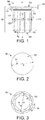
- FIG. 4 is a cross section depicting a composite resin assembly 400 (e.g., a carbon fiber assembly 400) including a rigid outer layer or skin 402 and a carbon fiber laminate 404.
- the carbon fiber laminate 404 of FIG. 4 includes four carbon fiber layers 404A-404D, but it will be appreciated that a carbon fiber laminate can include two or more carbon fiber layers, and may include 100 or more layers.
- the carbon fiber assembly 400 includes a region 406 to undergo rework or repair (hereinafter, generally referred to collectively as rework).
- FIG. 4 further depicts a surface or layer 408 that prevents access to the back surface 410 of the carbon fiber laminate 404, where the back surface 410 and the layer 408 are separated by a gap 412. Access to the back surface 410 is typically required to properly establish a vacuum from the skin 402 side of the carbon fiber assembly 400.
- the layer 408 may include a plurality of layers and may be part of the carbon fiber assembly 400 or another surface.
- FIG. 5 depicts the FIG. 4 structure after forming or shaping a hole 500 through the skin 402 and carbon fiber laminate 404 of the carbon fiber assembly 400.
- the portion of the hole 500 through the skin 402 has a larger diameter D 2 than the diameter D 1 of the surface 102 of the flange 108 ( FIG. 2 ) of the hole plug 100. Further D 2 is larger than a diameter D 3 of the portion of the hole 500 through the carbon fiber laminate 404.
- the carbon fiber laminate 404 around the hole 500 can include a sloping face 502 (i.e., cant 502) that forms a countersink for the hole 500, where the cant 502 approximates or matches the bevel 112 of the hole plug 100.
- the hole 500 can be formed using, for example, a drill bit and countersink tool known in the art (not individually depicted for simplicity).
- the measurements of the FIG. 4 structure, particularly the carbon fiber assembly 400 and the hole 500 therethrough, can be used to determine the shape of the hole plug 100 used for the rework.
- the hole plug 100 can be formed by 3D printing after forming the hole 500.
- the hole plug 100 can be formed prior to forming the hole 500, where the hole 500 is shaped to match the hole plug 100.
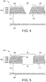
- an adhesive material 600 can be applied to the grooves 118 of the hole plug 100. The hole plug can then be placed either completely into the hole 500 as depicted in FIG. 7 , or partially into the hole 500 as depicted in FIG. 6 . In the position of FIG.
- the elongated portion of the shank 114 below the nubs 122 stabilize the hole plug 100 within the hole in the carbon fiber laminate 404.
- additional adhesive 600 can be placed around the hole plug 100, for example, around and/or into the notch 116, after which the hole plug 100 is inserted fully into the hole 500 as depicted in FIG. 7 . Excessive adhesive is removed to result in a structure similar to FIG. 7 .
- the hole plug 100 is designed so that the tops of the nubs 122 (i.e., the upper edges between surface 102 and the midpoint W, FIG. 1 ) are positioned at or near the level of the back surface 410.
- the nubs 122 thus prevent the hole plug 100 from falling or popping out of the hole 500 prior to the curing of the adhesive 600, even under the force of gravity or the application of a certain amount of vacuum force.
- the nubs 122 loosely secure or "lock" the hole plug 100 onto the composite laminate 404, possibly in the absence of cured or uncured adhesive or other discrete mechanical attachments, and thus can be referred to as a "locking" hole plug.
- the upper surface 102 of the hole plug 100 is at a level that is below the exposed upper surface 700 of the skin 402 so that the rework region 406 can be continuous and level with the exposed upper surface 700 after completion of the rework.
- the elongated portion of the shank 114 between the bottom of the nubs 122 and the chamfer 120 ensures that a sufficient amount or volume of adhesive is carried within the grooves 118 by the hole plug 100 through the hole in the carbon fiber laminate 404 and to the back surface 410 to properly bond the hole plug 100 to the carbon fiber laminate 404.
- the adhesive 600 is cured, thereby bonding the hole plug 100 to the carbon fiber layers 404A-404D of the carbon fiber laminate 404.
- the rework can include applying one or more repair layers 800 to the region 406 as depicted in FIG. 8 .
- a vacuum assembly 802 which may include a vacuum bag 804, a vacuum nozzle 806, and a vacuum line 808 connected to a vacuum 810 can be applied to the region 406.
- the vacuum assembly 802 may be used to debulk the one or more repair layers 800, and to remove excess resin as the one or more repair layers 800 are cured.
- the vacuum assembly 802 is removed from the upper exposed surface 700 of the skin 402, and additional processing is performed on the repair layer 800 and skin 402 to result in the completed structure of FIG. 9 .
- the hole plug 100 thus remains part of the carbon fiber assembly 400.
- the region 406 to undergo rework or repair may be a solid surface such that the structure of FIG. 9 is completed.
- the region 406 of FIG. 4 can be or include a damaged region around a fastening hole.
- the fastening hole can be temporarily filled and sealed using the hole plug 100 and repaired as described above with reference to FIGS. 4-8 result in the structure of FIG. 9 .
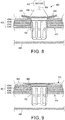
- the structure of FIG. 9 can be further processed, for example, by drilling out and/or otherwise removing the hole plug 100 to result in the fastening hole 1000 of FIG. 10 .
- the fastening hole 1000 can be lined with a liner 1002, for example, to protect the carbon fiber laminate 404 or to prepare the fastening hole 1000 for insertion of a fastener (not individually depicted for simplicity).
- FIG. 11 is a functional block diagram depicting a composite laminate 1100 having a first hole 1102 therethrough, and a hole plug 1104 positioned within the first hole 1102.
- the composite laminate 1100 can be or include one or more layers, for example, one or more carbon fiber layers.
- the FIG. 11 structure further depicts a skin 1106 that can be a solid shell that overlies and covers the composite laminate 1100.
- the skin 1106 can have a second hole 1108 therethrough.
- the hole plug 1104 can be inserted through the second hole 1108 to result in the positioning of the hole plug 100 within the first hole 1102.
- a first width or first diameter D 5 of the first hole 1102 is smaller than a second width or second diameter D 6 of the second hole 1108.
- the 10 includes a flange 1110, a bevel 1112 extending from the flange 1110, and a shank 1114 extending from the bevel 1112.
- the shank 1114 can include a notch 1116 that can extend partially or completely around a circumference of the shank 1114.
- the shank 1114 further includes a plurality of grooves 1118 extending longitudinally along a height of the shank 1114.
- a plurality of nubs 1120 and a chamfer 1122 extend from the shank 1114.
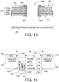
- FIG. 12 is a flow chart depicting a method 1200 for reworking a workpiece such as a fiber resin assembly 400 which may be a carbon fiber assembly 400 according to an implementation of the present teachings.
- the method 1200 can proceed by operation or use of one or more of the structures depicted in the figures described above, and thus is described with reference to FIGS. 1-9 ; however, it will be appreciated that the method 1200 is not limited to any particular structure or use unless expressly stated herein. It will be appreciated that while the method 1200 is described as a series of acts or events, the present teachings are not limited by the ordering of such acts or events. Some acts can occur in different orders and/or concurrently with other acts or events apart from those described herein. Further, a method in accordance with the present teachings can include other acts or events that have not been shown for simplicity, while other illustrated acts or events can be removed or modified.
- a rework area of a workpiece 400 is processed to define a hole 500 within the workpiece as at 1202.
- the hole 500 can have a first diameter D 2 through a first region (e.g., skin 402) of the workpiece 400 that is larger than a second diameter D 3 through a second region 404 (e.g., a carbon fiber laminate 404) of the workpiece.
- the second region 404 of the workpiece can be formed to define a cant 502.
- a hole plug 100 is formed, for example, using 3D printing, a molding process, or another suitable process as at 1204.
- the hole plug 100 can be formed after forming the hole 500 based on measurements of the hole 500, or the hole 500 can be formed to match the dimensions of an existing hole plug 100.
- the hole plug 100 can include a flange 108 having a third diameter D 1 that is smaller than the first diameter D 2 .
- adhesive 600 is applied to grooves 118 of the hole plug 100, and the hole plug 100 is partially inserted into the hole 500 as at 1208.
- the hole plug 100 is partially inserted such that a lower edge of nubs 122 around a shank 114 of the hole plug 100 rest on the second region such as the cant 502.
- additional adhesive 600 can be applied to the hole plug 100, for example, to a notch 116 as at 1210.
- the notch 116 and grooves 118 thus provide a carrier for the adhesive 600 as it is inserted into the hole 500, thereby spreading or dispersing a sufficient volume or quantity of the adhesive 600 to other portions of the shank 114 and the workpiece to ensure bonding of the hole plug 100 to the workpiece 400.
- the hole plug 100 is fully inserted into the hole 500.
- an upper surface 102 of the hole plug 100 is recessed within an exposed upper surface 700 of the skin 402.
- a vacuum bag 804 is applied to a region 406 of the workpiece 400 including the hole plug 100 and one or more repair layers 800.
- a vacuum force can be applied to the workpiece 400, the one or more repair layers 800, and the locking hole plug 100 as at 1216.
- the application of the vacuum force can debulk the one or more repair layers 800 that overlie the workpiece 400 and the locking hole plug 100, as at 1218.
- the adhesive 600 is cured, either passively using a timed cure at ambient temperatures or by performing active processing acts such as heating the adhesive 600, exposing the adhesive to ultraviolet light, etc.
- additional processing of the region 406 can optionally be performed to complete the rework as at 1222.
- the rework can include one or more of applying additional layers and adhesives, sanding and/or curing the additional layers 800, applying a vacuum to the additional layer 800 using a vacuum assembly 802, painting or otherwise finishing the workpiece 400.
- the rework can also optionally include drilling out and removing the hole plug 100 to form a fastening hole 1000, lining the fastening hole 1000 with a liner 1002, and/or other processing acts.
- a hole plug according to an example implementation of the present teachings thus provides a structure and technique for reworking a workpiece.
- the hole plug is secured within a hole defined by the workpiece such that processing of the workpiece can be performed.
- the processing of the workpiece can include the application of a vacuum force to the rework area during a cure and/or other processing of a repair layer.
- the numerical values as stated for the parameter can take on negative values.
- the example value of range stated as "less than 10" can assume negative values, e.g. - 1, -2, -3, -10, -20, -30, etc.
- the term “on” used with respect to two materials, one “on” the other, means at least some contact between the materials, while “over” means the materials are in proximity, but possibly with one or more additional intervening materials such that contact is possible but not required. Neither “on” nor “over” implies any directionality as used herein.
- the term “conformal” describes a coating material in which angles of the underlying material are preserved by the conformal material. The term “about” indicates that the value listed may be somewhat altered, as long as the alteration does not result in nonconformance of the process or structure to the illustrated implementation.
- “exemplary” indicates the description is used as an example, rather than implying that it is an ideal. Other implementations of the present teachings will be apparent to those skilled in the art from consideration of the specification and practice of the disclosure herein. It is intended that the specification and examples be considered as exemplary only, the claimed invention being indicated by the following claims.
- Terms of relative position as used in this application are defined based on a plane parallel to the conventional plane or working surface of a workpiece, regardless of the orientation of the workpiece.
- the term “horizontal” or “lateral” as used in this application is defined as a plane parallel to the conventional plane or working surface of a workpiece, regardless of the orientation of the workpiece.
- the term “vertical” refers to a direction perpendicular to the horizontal. Terms such as “on,” “side” (as in “sidewall”), “higher,” “lower,” “over,” “top,” and “under” are defined with respect to the conventional plane or working surface being on the top surface of the workpiece, regardless of the orientation of the workpiece.
Description
- The present teachings relate to the field of composite structures formed from composite materials and, more particularly, to rework and repair of composite structures. Composite materials such as composite fiber reinforced polymer are commonly used in various industries for their advantages of weight, strength, rigidity, moldability into complex contoured shapes, etc., compared to some other materials. In the aerospace industry, composite fiber reinforced polymers (referred to herein collectively as "carbon composite" for simplicity) are commonly used to form various aircraft structures or portions of structures such as fuselages, wings, empennages, etc. The carbon composite can include multiple layers of carbon fiber sheets laminated together using a resin adhesive, matrix, or binder. To complete a carbon fiber assembly that includes the carbon composite, an outer shell or skin panel (i.e., skin) can be attached with fasteners to an inner frame that can include metal stringers and ribs.
- While carbon composites provide a robust strength and durability, rework and/or repair of fatigued, damaged, or other regions or areas is occasionally required. A region to undergo rework may be caused, for example, by physical contact with other objects, gradual wear, material or manufacturing defects, wind damage, lightning strike, chemical damage, fatigue, or other causes. In other cases, the region may result from rework of the structure, for example, from installing additional framework that supports the composite layer. The region may include only surface damage to the skin or may extend further into the carbon composite.
- In some cases, depending on surrounding structures, the composite resin can be reworked or repaired by removing the damaged area, applying a fiber patch and an epoxy resin with a curing agent, curing the resin, then sanding and finishing the fiber patch and surrounding areas to complete the repair. Generally, a vacuum force is applied to the fiber patch during the resin cure to compact the two or more fiber layers that make up the fiber patch by removing air and volatile gases from within and between the laminated layers, and to remove excess resin.
- Document
JP 2015 183695 A - Document
DE 10 2017 127 719 A1 states in its abstract:" Repair method for a fibre composite workpiece, wherein the fibre composite workpiece has a damage site , in which a repair area is created at the damage site by removing structural material of the fibre composite workpiece, wherein the repair area has a repair base area, wherein the repair area is provided with at least one step, which closedly surrounds a normal oriented transversely and in particular perpendicularly to the repair base region, wherein the at least one step has an orientation-dependent length defined along a radial direction oriented perpendicularly to the normal, wherein, in the manufacture of the repair area, the length of the at least one step is varied as a function of an angle between an orientation of the radial direction and a main fiber orientation of the fiber composite workpiece, wherein, in the manufacture of the repair area, the length of the at least one step is chosen to be greatest in a radial direction parallel to the main fiber orientation of the fiber composite workpiece during the manufacture of the repair area, wherein a ratio of a width of the at least one step as defined longitudinally to the normal, to the length is varied as a function of the angle, and wherein a repair workpiece which has a positive shape corresponding to a negative shape of the repair area, is arranged on the repair area. - Improved structures, methods, and kits for repairing composite structures would be a welcome addition to the art.
- The following presents a simplified summary in order to provide a basic understanding of some aspects of one or more implementations of the present teachings. This summary is not an extensive overview, nor is it intended to identify key or critical elements of the present teachings, nor to delineate the scope of the disclosure. Rather, its primary purpose is merely to present one or more concepts in simplified form as a prelude to the detailed description presented later.
- A hole plug of the present claimed invention is defined in claim 1. A composite fiber assembly of the claimed invention is defined in claim 11. A method for reworking a region of a composite resin assembly of the claimed invention, using the hole plug, of claim 1, is defined in claim 12.
- In an implementation of the present teachings, a hole plug includes a flange having a first diameter, wherein the flange is positioned at a first end of the hole plug, a bevel extending from, and intersecting, the flange at an angle, a shank extending from the bevel away from the flange to a second end of the hole plug opposite the first end, the shank including a second diameter that is smaller than the first diameter and a plurality of longitudinal grooves defined by the shank and oriented around an exterior of the shank. The hole plug further includes a plurality of nubs positioned on, and extending from, the exterior of the shank, wherein the plurality of nubs are positioned between the plurality of longitudinal grooves.
- In the above defined hole plug, the plurality of nubs each include a radius and a tangent of each radius parallel to a longitudinal axis of the hole plug intersects the flange within the first diameter. The hole plug can further include a circumferential notch defined by the shank, wherein the circumferential notch is positioned between the plurality of longitudinal grooves and the flange. The plurality of nubs can each include a first height that is parallel to a longitudinal axis of the hole plug. The plurality of longitudinal grooves each have a second height that is parallel to the longitudinal axis of the hole plug and greater than the first height, and the plurality of longitudinal grooves can be positioned closer to the first end and the second end of the hole plug than the plurality of nubs. The second end of the hole plug can include a chamfered surface, and the plurality of longitudinal grooves can extend into the chamfered surface.
- Additionally each nub can define a radius, such that the plurality of nubs define a plurality of radii. Each radius can include a tangent that is parallel to a longitudinal axis of the hole plug, and each tangent of each radius intersects the flange within the first diameter.
- In an implementation, the hole plug can have a third diameter through a first nub, through the shank, and through a second nub that is opposite the first nub, and the third diameter can be less than the first diameter and greater than the second diameter. The hole plug can be formed from a single piece of material, and the single piece of material can be maraging steel. The hole plug can have a surface roughness, wherein an average roughness centerline "Ra" of the surface roughness is from 250 microns (µm) to 400 µm. Further,
- In another example, a composite fiber assembly includes a composite laminate and a skin overlying the composite laminate, the composite laminate and the skin having a hole therethrough, wherein a first hole diameter of the hole through the skin is larger than a second hole diameter of the hole through the composite laminate. The composite fiber assembly further includes a hole plug within the hole, the hole plug having a flange having a third diameter, wherein the flange is positioned at a first end of the hole plug, a bevel extending from, and intersecting, the flange at an angle, a shank extending from the bevel away from the flange to a second end of the hole plug opposite the first end. The shank includes a fourth diameter that is smaller than the third diameter and a plurality of longitudinal grooves defined by the shank and oriented around an exterior of the shank. The hole plug further includes a plurality of nubs positioned on, and extending from, the exterior of the shank, wherein the plurality of nubs are positioned between the plurality of longitudinal grooves, and wherein the composite laminate physically contacts the hole plug between the flange and the plurality of nubs.
- The hole plug can further include a circumferential notch defined by the shank and the circumferential notch is positioned between the plurality of longitudinal grooves and the flange. The plurality of nubs can have a first height that is parallel to a longitudinal axis of the hole plug, the plurality of longitudinal grooves can each have a second height that is parallel to the longitudinal axis of the hole plug and greater than the first height, and the plurality of longitudinal grooves can be positioned closer to the first end and the second end of the hole plug than the plurality of nubs. The hole plug can further include a chamfered surface at the second end, wherein the plurality of longitudinal grooves extend into the chamfered surface.
- Another example includes a method for reworking a region of a composite resin assembly having a composite laminate and a skin overlying the composite laminate. The method includes defining a hole within the region of the composite resin assembly, wherein the hole comprises a first diameter within the skin and a second diameter within the composite laminate, and the first diameter is larger than the second diameter, applying an adhesive to a plurality of grooves defined by a shank of a hole plug, fully inserting the hole plug into the hole, wherein the hole plug is recessed within the skin, curing the adhesive, and subsequent to curing the adhesive, completing the reworking of the region. The completing of the reworking of the region can optionally include applying a vacuum bag to the region subsequent to curing the adhesive and applying a vacuum force to the region and to the hole plug. The applying of the vacuum force to the region can debulk one or more repair layers overlying the hole plug. The method can further include forming a cant on the composite laminate, partially inserting the hole plug into the hole, wherein nubs extending from the shank of the hole plug rest on the cant, and applying the adhesive to a notch that encircles the shank of the hole plug.
- The accompanying drawings, which are incorporated in, and constitute a part of this specification, illustrate implementations of the present teachings and, together with the description, serve to explain the principles of the disclosure. In the figures:
-
FIG. 1 is a side view of a hole plug in accordance with an implementation of the present teachings. -
FIG. 2 is a plan view or top view of the hole plug ofFIG. 1 . -
FIG. 3 is a bottom view of the hole plug ofFIG. 1 . -
FIG. 4 is a cross section of a composite fiber assembly having a area for repair or rework. -
FIG. 5 depicts theFIG. 4 structure after forming or shaping a hole therethrough. -
FIG. 6 depicts theFIG. 5 structure after partially inserting a hole plug into the hole. -
FIG. 7 depicts theFIG. 6 structure after fully inserting the hole plug into the hole. -
FIG. 8 depicts theFIG. 7 structure during repair or rework. -
FIG. 9 depicts theFIG. 8 structure after completing the repair or rework. -
FIG. 10 depicts theFIG. 9 structure after drilling out the hole plug and lining a resulting fastening hole with a liner. -
FIG. 11 is a functional block diagram depicting a hole plug within a hole of a composite laminate. -
FIG. 12 is a flow chart of a method for repairing or reworking a workpiece. - It should be noted that some details of the figures have been simplified and are drawn to facilitate understanding of the present teachings rather than to maintain strict structural accuracy, detail, and scale.
- Reference will now be made in detail to exemplary implementations of the present teachings, examples of which are illustrated in the accompanying drawings. Wherever convenient, the same reference numbers will be used throughout the drawings to refer to the same or like parts. It will be understood that the structures referenced herein may include additional features which are not depicted for simplicity, while various depicted structures may be removed or modified.
- As discussed above, a vacuum force can be applied to a surface area during repair of a carbon composite. The vacuum force debulks the two or more fiber layers by removing air and volatile gases from within and between the laminated layers, and removes excess resin.
- As discussed above, some structures can include a carbon composite covered by a hard skin panel to form a composite fiber assembly. The composite fiber assembly can include a pair of adjacent or parallel surfaces that form a hollow area or gap between the adjacent surfaces. This construction can impede or prevent access to the back side of the surface undergoing repair or rework (i.e., the repair surface). When this hollow area has a high volume or is open to the inflow of air or other gases, a vacuum force on the repair surface during the cure of the repair patch can be difficult or impossible to establish and, if applied, can result in the repair patch lifting away from the repair surface.
- The present teachings thus include a hole plug that can be positioned through the laminated layers of the carbon composite. The hole plug fills the opening through the carbon composite and simplifies the repair of the structure.
-
FIG. 1 is a side view,FIG. 2 is a bottom view, andFIG. 3 is a top view of ahole plug 100 in accordance with an example implementation of the present teachings. The hole plug design includes various features for use with carbon composites such as multilayer carbon fiber resin structures as described below. It will be appreciated that thehole plug 100 depicted in the figures is an exemplary implementation, and that other implementations may include other features that have not been depicted for simplicity, while various depicted features may be removed or modified. - The
hole plug 100 in the implementation ofFIG. 1 includes a first orupper surface 102 at a first end of thehole plug 100, a second orlower surface 104 at a second end of thehole plug 100, and abody 106 positioned between theupper surface 102 and the lower surface 104 (i.e., between the first end and the second end). The upper 102 and lower 104 surfaces can be planar or generally planar, and parallel or generally parallel with each other. Thebody 106 includes a flange 108 that can intersect theupper surface 102 at an angle of about 90° ± 5° and has athickness 110. Thebody 106 further includes abevel 112 that intersects the flange 108 and ashank 114 that intersects thebevel 112. Thebevel 112 can have an angle of about 100° ± 5° relative to a longitudinal axis A that extends through a center of thehole plug 100, or another angle that matches a countersink of the hole it is being used to fill as described in more detail below. Abevel 112 with an angle of less than 95° or greater than 105° can result in a poor adhesive bond with the carbon fiber laminate, and may result in leakage of air around thehole plug 100 upon the application of a vacuum during use. Theshank 114 can be generally parallel with the longitudinal axis A. - The
shank 114 defines anotch 116 that can encircle an entirety of theshank 114 around the longitudinal axis A, thus providing a circumferential notch. Two linear edges of thenotch 116 can intersect to form an angle theta 1 (θ1) of about 45° ± 5°. Theshank 114 further defines, at least in part, a plurality ofgrooves 118. Eachgroove 118 has a height that is parallel to the longitudinal axis A and a width that is perpendicular to the longitudinal axis A, where the height is greater than the width, and thus formlongitudinal grooves 118. The plurality ofgrooves 118 extend along a majority of theshank 114 parallel to the longitudinal axis A. Further, the plurality ofgrooves 118 extend into achamfered surface 120 orchamfer 120, and thus thechamfer 120 defines a portion of each of the plurality ofgrooves 118.FIG. 3 depicts eightgrooves 118 generally equally spaced around the circumference of thehole plug 100, and thus a center of eachgroove 118 is spaced from each of twoadjacent grooves 118 by 45° around the circumference of thehole plug 100. Two linear edges of eachgroove 118 can intersect to form an angle theta 2 (θ2) of about 97.2° ± 5°. - The
hole plug 100 further includes a plurality of locking detents, bumps, retention members, or nubs 122 (hereinafter, collectively, "nubs") that extend from theshank 114.FIGS. 1 and 3 depict onenub 122 positioned between each pair ofadjacent grooves 118. Thenubs 122 are generally equally spaced around the circumference of thehole plug 100, and thus a center of eachnub 122 is spaced from each of two adjacent nubs by 45° around the circumference of thehole plug 100. Eachnub 122 can include, for example, a spherical sector, a spherical slice, a hemisphere, etc., having a radius, such that the plurality of nubs define a plurality of radii. As depicted inFIG. 1 , a tangent T of the radius of eachnub 122 that is parallel to the longitudinal axis A intersects thebevel 112 within an outside diameter D1 (FIG. 2 ) of the flange 108. In another aspect, a width W of thehole plug 100 through the longitudinal axis A and through a pair ofnubs 122 that are positioned on opposite sides of theshank 114 is less than the outside diameter D1 of the flange 108. Additionally, a circumference of thehole plug 100 around a midpoint of the nubs 122 (generally circumferentially around width "W" inFIG. 1 ) is less than a circumference of thehole plug 100 around the outer vertical surface of the flange 108. Moreover, an outside diameter D4 (FIG. 3 ) of theshank 114 is less than the outside diameter D1 of the flange 108. - The midpoint of the
nubs 122 depicted at the width W inFIG. 1 should be the approximate middle of thehole plug 100 betweenupper surface 102 andlower surface 104. In this aspect, "W" inFIG. 1 refers to the middle or midpoint of thehole plug 100, where 50% of an overall height of thehole plug 100 is above midpoint W and 50% of the overall height of thehole plug 100 is below midpoint W. As depicted, the plurality ofgrooves 118 are positioned closer to thefirst surface 102 at the first end and to thesecond surface 104 at the second end of the hole plug than are the plurality ofnubs 122, which aids in dispersing a sealant (e.g., adhesive) as described below. - The surface of the
chamfer 120 intersects the surface of theshank 114 and thelower surface 104 as depicted inFIG. 1 , and forms an angle theta 3 (θ3) with thelower surface 104. The angle θ3 can be about 131° ± 5°. - With regard to use, the
hole plug 100 can be designed so that the diameter D1 of the flange 108 (e.g., the diameter D1 of the upper surface 102) is larger than the minimum diameter of the hole for which it is used (i.e., the hole through the carbon fiber resin laminate) and smaller than the largest diameter of the hole through the exterior surface (i.e., the hole through the exterior skin) of the composite fiber assembly. Further, thethickness 110 of the flange 108 must have a sufficient thickness to withstand the loads and/or forces that it will undergo during installation as described below. The bevel 112 (e.g., the angle and height of the bevel 112) is designed to match a countersink of the hole for which it is designed. - The
notch 116 can be included to facilitate bonding at an interface of the bottom of the skin. Thenotch 116 provides an additional adhesive carrier or receptacle that at least partially attaches thehole plug 100 to the carbon fiber laminate. Similarly,grooves 118 running parallel to theshank 114 and to the longitudinal axis A are designed as an additional adhesive carrier or receptacle for attachment to the carbon fiber laminate. Both thenotch 116 andgrooves 118 can also provide some frictional resistance to maintain thehole plug 100 in place prior to curing of the adhesive. Thegrooves 118 should extend both above and below thenubs 122 so that the adhesive is carried through the length of the hole that receives thehole plug 100. - The
nubs 122 are sized to be sufficiently large to maintain thehole plug 100 within the hole in the carbon fiber laminate but small enough to prevent damaged to the carbon fiber laminate as they pass through the hole. The length of thechamfer 120 and the angle θ3 of the chamfer are designed to ease installation of thehole plug 100 into the hole in the carbon fiber assembly during repair. A minimum length of the body 106 (i.e., the total length of the hole plug 100) is designed for ease of installation of thehole plug 100, but also helps prevent thenubs 122 from breaking or fracturing off of theshank 114 during installation. - A surface roughness of the
hole plug 100 contributes to the mechanical bond of the adhesive to thehole plug 100. In an implementation, thehole plug 100 can have a surface roughness, wherein an average roughness centerline "Ra" of the surface roughness is from 250 microns (µm) to 400 µm. - The
hole plug 100 can be formed, for example, using an additive manufacturing process such as a three dimensional (3D) printing process. The 3D printing process can include laser sintering of a metal or metal alloy, such as maraging steel. In another manufacturing process, thehole plug 100 can be formed using a molding process of a metal, metal alloy, or a suitable synthetic such as a polymer. Thehole plug 100 can be formed as a single solid structure or single piece of material, although other constructions, such as formation from two or more materials or layers, or the formation of ahollow hole plug 100 to reduce weight, are contemplated. The surface roughness described above can result form the 3D printing process, molding process, or another formation process, or can result from a separate method act such as one or more of chemical etching, mechanical etching, or chemical-mechanical etching. - Various uses and techniques for using the
hole plug 100 in accordance are contemplated. An example use is depicted inFIGS. 4-9 .FIG. 4 is a cross section depicting a composite resin assembly 400 (e.g., a carbon fiber assembly 400) including a rigid outer layer orskin 402 and acarbon fiber laminate 404. Thecarbon fiber laminate 404 ofFIG. 4 includes four carbon fiber layers 404A-404D, but it will be appreciated that a carbon fiber laminate can include two or more carbon fiber layers, and may include 100 or more layers. Thecarbon fiber assembly 400 includes aregion 406 to undergo rework or repair (hereinafter, generally referred to collectively as rework). Theregion 406 to undergo rework may result from damage, maintenance, reconstruction, or reinforcing of the carbon fiber assembly, or any another cause. For purposes of illustration,FIG. 4 further depicts a surface orlayer 408 that prevents access to theback surface 410 of thecarbon fiber laminate 404, where theback surface 410 and thelayer 408 are separated by agap 412. Access to theback surface 410 is typically required to properly establish a vacuum from theskin 402 side of thecarbon fiber assembly 400. Thelayer 408 may include a plurality of layers and may be part of thecarbon fiber assembly 400 or another surface. -
FIG. 5 depicts theFIG. 4 structure after forming or shaping ahole 500 through theskin 402 andcarbon fiber laminate 404 of thecarbon fiber assembly 400. As depicted, the portion of thehole 500 through theskin 402 has a larger diameter D2 than the diameter D1 of thesurface 102 of the flange 108 (FIG. 2 ) of thehole plug 100. Further D2 is larger than a diameter D3 of the portion of thehole 500 through thecarbon fiber laminate 404. Further, thecarbon fiber laminate 404 around thehole 500 can include a sloping face 502 (i.e., cant 502) that forms a countersink for thehole 500, where thecant 502 approximates or matches thebevel 112 of thehole plug 100. Thehole 500 can be formed using, for example, a drill bit and countersink tool known in the art (not individually depicted for simplicity). - The measurements of the
FIG. 4 structure, particularly thecarbon fiber assembly 400 and thehole 500 therethrough, can be used to determine the shape of thehole plug 100 used for the rework. In one implementation, thehole plug 100 can be formed by 3D printing after forming thehole 500. In another implementation, thehole plug 100 can be formed prior to forming thehole 500, where thehole 500 is shaped to match thehole plug 100. After forming theshaped hole 500 and thehole plug 100, anadhesive material 600 can be applied to thegrooves 118 of thehole plug 100. The hole plug can then be placed either completely into thehole 500 as depicted inFIG. 7 , or partially into thehole 500 as depicted inFIG. 6 . In the position ofFIG. 6 , the elongated portion of theshank 114 below thenubs 122 stabilize thehole plug 100 within the hole in thecarbon fiber laminate 404. In the position ofFIG. 6 , additional adhesive 600 can be placed around thehole plug 100, for example, around and/or into thenotch 116, after which thehole plug 100 is inserted fully into thehole 500 as depicted inFIG. 7 . Excessive adhesive is removed to result in a structure similar toFIG. 7 . - As depicted in
FIG. 7 , thehole plug 100 is designed so that the tops of the nubs 122 (i.e., the upper edges betweensurface 102 and the midpoint W,FIG. 1 ) are positioned at or near the level of theback surface 410. Thenubs 122 thus prevent thehole plug 100 from falling or popping out of thehole 500 prior to the curing of the adhesive 600, even under the force of gravity or the application of a certain amount of vacuum force. In one aspect, thenubs 122 loosely secure or "lock" thehole plug 100 onto thecomposite laminate 404, possibly in the absence of cured or uncured adhesive or other discrete mechanical attachments, and thus can be referred to as a "locking" hole plug. Further, theupper surface 102 of thehole plug 100 is at a level that is below the exposedupper surface 700 of theskin 402 so that therework region 406 can be continuous and level with the exposedupper surface 700 after completion of the rework. The elongated portion of theshank 114 between the bottom of thenubs 122 and thechamfer 120 ensures that a sufficient amount or volume of adhesive is carried within thegrooves 118 by thehole plug 100 through the hole in thecarbon fiber laminate 404 and to theback surface 410 to properly bond thehole plug 100 to thecarbon fiber laminate 404. After forming theFIG. 7 structure, the adhesive 600 is cured, thereby bonding thehole plug 100 to the carbon fiber layers 404A-404D of thecarbon fiber laminate 404. - Subsequently, additional processing can be performed to rework the
region 406 that includes thehole plug 100. The rework can include applying one or more repair layers 800 to theregion 406 as depicted inFIG. 8 . Avacuum assembly 802, which may include avacuum bag 804, avacuum nozzle 806, and avacuum line 808 connected to avacuum 810 can be applied to theregion 406. Thevacuum assembly 802 may be used to debulk the one or more repair layers 800, and to remove excess resin as the one or more repair layers 800 are cured. After curing the one or more repair layers 800, thevacuum assembly 802 is removed from the upper exposedsurface 700 of theskin 402, and additional processing is performed on therepair layer 800 andskin 402 to result in the completed structure ofFIG. 9 . Thehole plug 100 thus remains part of thecarbon fiber assembly 400. - With regard to the structure depicted in
FIGS. 4-9 , theregion 406 to undergo rework or repair may be a solid surface such that the structure ofFIG. 9 is completed. In another implementation, theregion 406 ofFIG. 4 can be or include a damaged region around a fastening hole. In this implementation, the fastening hole can be temporarily filled and sealed using thehole plug 100 and repaired as described above with reference toFIGS. 4-8 result in the structure ofFIG. 9 . Subsequently, the structure ofFIG. 9 can be further processed, for example, by drilling out and/or otherwise removing thehole plug 100 to result in thefastening hole 1000 ofFIG. 10 . In an implementation, thefastening hole 1000 can be lined with aliner 1002, for example, to protect thecarbon fiber laminate 404 or to prepare thefastening hole 1000 for insertion of a fastener (not individually depicted for simplicity). - It will be appreciated that the figures have been simplified and are drawn to facilitate understanding of the present teachings and are not to scale.
-
FIG. 11 is a functional block diagram depicting acomposite laminate 1100 having afirst hole 1102 therethrough, and ahole plug 1104 positioned within thefirst hole 1102. Thecomposite laminate 1100 can be or include one or more layers, for example, one or more carbon fiber layers. TheFIG. 11 structure further depicts askin 1106 that can be a solid shell that overlies and covers thecomposite laminate 1100. Theskin 1106 can have asecond hole 1108 therethrough. Thehole plug 1104 can be inserted through thesecond hole 1108 to result in the positioning of thehole plug 100 within thefirst hole 1102. A first width or first diameter D5 of thefirst hole 1102 is smaller than a second width or second diameter D6 of thesecond hole 1108. Thehole plug 1104 ofFIG. 10 includes aflange 1110, abevel 1112 extending from theflange 1110, and ashank 1114 extending from thebevel 1112. Theshank 1114 can include anotch 1116 that can extend partially or completely around a circumference of theshank 1114. Theshank 1114 further includes a plurality ofgrooves 1118 extending longitudinally along a height of theshank 1114. A plurality ofnubs 1120 and achamfer 1122 extend from theshank 1114. -
FIG. 12 is a flow chart depicting amethod 1200 for reworking a workpiece such as afiber resin assembly 400 which may be acarbon fiber assembly 400 according to an implementation of the present teachings. Themethod 1200 can proceed by operation or use of one or more of the structures depicted in the figures described above, and thus is described with reference toFIGS. 1-9 ; however, it will be appreciated that themethod 1200 is not limited to any particular structure or use unless expressly stated herein. It will be appreciated that while themethod 1200 is described as a series of acts or events, the present teachings are not limited by the ordering of such acts or events. Some acts can occur in different orders and/or concurrently with other acts or events apart from those described herein. Further, a method in accordance with the present teachings can include other acts or events that have not been shown for simplicity, while other illustrated acts or events can be removed or modified. - In an implementation, a rework area of a
workpiece 400 is processed to define ahole 500 within the workpiece as at 1202. Thehole 500 can have a first diameter D2 through a first region (e.g., skin 402) of theworkpiece 400 that is larger than a second diameter D3 through a second region 404 (e.g., a carbon fiber laminate 404) of the workpiece. Thesecond region 404 of the workpiece can be formed to define acant 502. Ahole plug 100 is formed, for example, using 3D printing, a molding process, or another suitable process as at 1204. Thehole plug 100 can be formed after forming thehole 500 based on measurements of thehole 500, or thehole 500 can be formed to match the dimensions of an existinghole plug 100. Thehole plug 100 can include a flange 108 having a third diameter D1 that is smaller than the first diameter D2. - Subsequently, as at 1206, adhesive 600 is applied to
grooves 118 of thehole plug 100, and thehole plug 100 is partially inserted into thehole 500 as at 1208. In an example implementation, thehole plug 100 is partially inserted such that a lower edge ofnubs 122 around ashank 114 of thehole plug 100 rest on the second region such as thecant 502. With thehole plug 100 partially inserted into the hole, additional adhesive 600 can be applied to thehole plug 100, for example, to anotch 116 as at 1210. Thenotch 116 andgrooves 118 thus provide a carrier for the adhesive 600 as it is inserted into thehole 500, thereby spreading or dispersing a sufficient volume or quantity of the adhesive 600 to other portions of theshank 114 and the workpiece to ensure bonding of thehole plug 100 to theworkpiece 400. Next, at 1212, thehole plug 100 is fully inserted into thehole 500. When fully inserted, anupper surface 102 of thehole plug 100 is recessed within an exposedupper surface 700 of theskin 402. Next, at 1214, avacuum bag 804 is applied to aregion 406 of theworkpiece 400 including thehole plug 100 and one or more repair layers 800. Subsequently, a vacuum force can be applied to theworkpiece 400, the one or more repair layers 800, and the lockinghole plug 100 as at 1216. The application of the vacuum force can debulk the one or more repair layers 800 that overlie theworkpiece 400 and the lockinghole plug 100, as at 1218. At 1220, the adhesive 600 is cured, either passively using a timed cure at ambient temperatures or by performing active processing acts such as heating the adhesive 600, exposing the adhesive to ultraviolet light, etc. Subsequently, additional processing of theregion 406 can optionally be performed to complete the rework as at 1222. The rework can include one or more of applying additional layers and adhesives, sanding and/or curing theadditional layers 800, applying a vacuum to theadditional layer 800 using avacuum assembly 802, painting or otherwise finishing theworkpiece 400. The rework can also optionally include drilling out and removing thehole plug 100 to form afastening hole 1000, lining thefastening hole 1000 with aliner 1002, and/or other processing acts. - A hole plug according to an example implementation of the present teachings thus provides a structure and technique for reworking a workpiece. The hole plug is secured within a hole defined by the workpiece such that processing of the workpiece can be performed. The processing of the workpiece can include the application of a vacuum force to the rework area during a cure and/or other processing of a repair layer.
- Notwithstanding that the numerical ranges and parameters setting forth the broad scope of the present teachings are approximations, the numerical values set forth in the specific examples are reported as precisely as possible. Any numerical value, however, inherently contains certain errors necessarily resulting from the standard deviation found in their respective testing measurements. Moreover, all ranges disclosed herein are to be understood to encompass any and all sub-ranges subsumed therein. For example, a range of "less than 10" can include any and all sub-ranges between (and including) the minimum value of zero and the maximum value of 10, that is, any and all sub-ranges having a minimum value of equal to or greater than zero and a maximum value of equal to or less than 10, e.g., 1 to 5. In certain cases, the numerical values as stated for the parameter can take on negative values. In this case, the example value of range stated as "less than 10" can assume negative values, e.g. - 1, -2, -3, -10, -20, -30, etc.
- While the present teachings have been illustrated with respect to one or more implementations, alterations and/or modifications can be made to the illustrated examples. For example, it will be appreciated that while the process is described as a series of acts or events, the present teachings are not limited by the ordering of such acts or events. Some acts may occur in different orders and/or concurrently with other acts or events apart from those described herein. Also, not all process stages may be required to implement a methodology in accordance with one or more aspects or implementations of the present teachings. It will be appreciated that structural components and/or processing stages can be added or existing structural components and/or processing stages can be removed or modified. Further, one or more of the acts depicted herein may be carried out in one or more separate acts and/or phases. Furthermore, to the extent that the terms "including," "includes," "having," "has," "with," or variants thereof are used in either the detailed description and the claims, such terms are intended to be inclusive in a manner similar to the term "comprising." The term "at least one of" is used to mean one or more of the listed items can be selected. As used herein, the term "one or more of" with respect to a listing of items such as, for example, A and B, means A alone, B alone, or A and B. Further, in the discussion and claims herein, the term "on" used with respect to two materials, one "on" the other, means at least some contact between the materials, while "over" means the materials are in proximity, but possibly with one or more additional intervening materials such that contact is possible but not required. Neither "on" nor "over" implies any directionality as used herein. The term "conformal" describes a coating material in which angles of the underlying material are preserved by the conformal material. The term "about" indicates that the value listed may be somewhat altered, as long as the alteration does not result in nonconformance of the process or structure to the illustrated implementation. Finally, "exemplary" indicates the description is used as an example, rather than implying that it is an ideal. Other implementations of the present teachings will be apparent to those skilled in the art from consideration of the specification and practice of the disclosure herein. It is intended that the specification and examples be considered as exemplary only, the claimed invention being indicated by the following claims.
- Terms of relative position as used in this application are defined based on a plane parallel to the conventional plane or working surface of a workpiece, regardless of the orientation of the workpiece. The term "horizontal" or "lateral" as used in this application is defined as a plane parallel to the conventional plane or working surface of a workpiece, regardless of the orientation of the workpiece. The term "vertical" refers to a direction perpendicular to the horizontal. Terms such as "on," "side" (as in "sidewall"), "higher," "lower," "over," "top," and "under" are defined with respect to the conventional plane or working surface being on the top surface of the workpiece, regardless of the orientation of the workpiece.
Claims (15)
- A hole plug (100, 1104), comprising:a flange (108, 1110) having a first diameter (D1), wherein the flange (108, 1110) is positioned at a first end of the hole plug (100, 1104);a bevel (112, 1112) extending from, and intersecting, the flange (108, 1110) at an angle;a shank (114, 1114) extending from the bevel (112, 1112) away from the flange (108, 1110) to a second end of the hole plug (100, 1104) opposite the first end, the shank (114, 1114) comprising:a second diameter (D4) that is smaller than the first diameter (D1); anda plurality of longitudinal grooves (118, 1118) defined by the shank (114, 1114) and oriented around an exterior of the shank (114, 1114); anda plurality of nubs (122, 1120) positioned on, and extending from, the exterior of the shank (114, 1114), wherein the plurality of nubs (122, 1120) are positioned between the plurality of longitudinal grooves (118, 1118)wherein:the plurality of nubs (122, 1120) each comprise a radius; anda tangent of each radius parallel to a longitudinal axis of the hole plug (100, 1104) intersects the flange (108, 1110) within the first diameter (D1).
- The hole plug (100, 1104) of claim 1, further comprising a circumferential notch (116, 1116) defined by the shank (114, 1114), wherein the circumferential notch (116, 1116) is positioned between the plurality of longitudinal grooves (118, 1118) and the flange (108, 1110).
- The hole plug (100, 1104) of any one of claims 1 to 2, wherein:the plurality of nubs (122, 1120) each have a first height that is parallel to a longitudinal axis of the hole plug (100, 1104);the plurality of longitudinal grooves (118, 1118) each have a second height that is parallel to the longitudinal axis of the hole plug (100, 1104) and greater than the first height; andthe plurality of longitudinal grooves (118, 1118) are positioned closer to the first end and the second end of the hole plug (100, 1104) than the plurality of nubs (122, 1120).
- The hole plug (100, 1104) of any one of claims 1 to 3, wherein the second end of the hole plug (100, 1104) comprises a chamfered surface (120, 1122).
- The hole plug (100, 1104) of claim 4, wherein the plurality of longitudinal grooves (118, 1118) extend into the chamfered surface (120, 1122).
- The hole plug (100, 1104) of claim 1, wherein:each nub (122, 1120) defines a radius, such that the plurality of nubs (122, 1120) define a plurality of radii;each radius comprises a tangent that is parallel to a longitudinal axis of the hole plug (100, 1104); andeach tangent of each radius intersects the flange (108, 1110) within the first diameter (D1).
- The hole plug (100, 1104) of any one of claims 1 to 6, wherein:the hole plug (100, 1104) has a third diameter (W) through a first nub (122, 1120), through the shank (114, 1114), and through a second nub (122, 1120) that is opposite the first nub (122, 1120); andthe third diameter (W) is less than the first diameter (D1) and greater than the second diameter (D4).
- The hole plug (100, 1104) of any one of claims 1 to 7, wherein the hole plug (100, 1104) is formed from a single piece of material.
- The hole plug (100, 1104) of claim 8 having a surface roughness, wherein an average roughness centerline "Ra" of the surface roughness is from 250 microns (µm) to 400 µm.
- The hole plug (100, 1104) of claim 8 or 9, wherein the single piece of material is maraging steel.
- A composite fiber assembly, comprising: a composite laminate and a skin overlying the composite laminate, the composite laminate and the skin having a hole therethrough, wherein a first hole diameter of the hole through the skin is larger than a second hole diameter of the hole through the composite laminate; a hole plug within the hole,wherein the hole plug is a hole plug according to any one of claims 1 to 10, andwherein the composite laminate physically contacts the hole plug between the flange and the plurality of nubs.
- A method (1200) for reworking a region (406) of a composite resin assembly (400) having a composite laminate (404, 1100) and a skin (402, 1106) overlying the composite laminate (404, 1100), the method (1200) using a hole plug according to any one of claims 1 to 10 and comprises:defining a hole (500) within the region (406) of the composite resin assembly (400), wherein the hole (500) comprises a first hole diameter (D2) within the skin (402, 1106) and a second hole diameter (D3) within the composite laminate (404, 1100), and the first hole diameter is larger than the second hole diameter;applying an adhesive (600) to a plurality of grooves (118, 1118) defined by a shank (114, 1114) of the hole plug (100, 1104);fully inserting the hole plug (100, 1104) into the hole (500), wherein the hole plug (100, 1104) is recessed within the skin (402, 1106);curing the adhesive (600); andsubsequent to curing the adhesive (600), completing the reworking of the region (406).
- The method of claim 12, wherein the completing of the reworking of the region comprises: applying a vacuum bag to the region subsequent to curing the adhesive; and applying a vacuum force to the region and to the hole plug.
- The method of claim 13, wherein the applying of the vacuum force to the region debulks one or more repair layers overlying the hole plug.
- The method of any one of claims 12 to 14, further comprising: forming a cant on the composite laminate; partially inserting the hole plug into the hole, wherein nubs extending from the shank of the hole plug rest on the cant; and applying the adhesive to a notch that encircles the shank of the hole plug.
Applications Claiming Priority (1)
| Application Number | Priority Date | Filing Date | Title |
|---|---|---|---|
| US16/049,317 US11577479B2 (en) | 2018-07-30 | 2018-07-30 | Locking hole plug for sealing holes in composite structures |
Publications (2)
| Publication Number | Publication Date |
|---|---|
| EP3603942A1 EP3603942A1 (en) | 2020-02-05 |
| EP3603942B1 true EP3603942B1 (en) | 2021-12-08 |
Family
ID=66776232
Family Applications (1)
| Application Number | Title | Priority Date | Filing Date |
|---|---|---|---|
| EP19178786.0A Active EP3603942B1 (en) | 2018-07-30 | 2019-06-06 | Locking hole plug for sealing holes in composite structures |
Country Status (8)
| Country | Link |
|---|---|
| US (2) | US11577479B2 (en) |
| EP (1) | EP3603942B1 (en) |
| JP (2) | JP7378992B2 (en) |
| KR (1) | KR20200013582A (en) |
| CN (1) | CN110775243A (en) |
| BR (1) | BR102019013423A2 (en) |
| CA (1) | CA3044409A1 (en) |
| SG (1) | SG10201905843SA (en) |
Families Citing this family (3)
| Publication number | Priority date | Publication date | Assignee | Title |
|---|---|---|---|---|
| DE102019107202A1 (en) * | 2019-03-20 | 2020-09-24 | Airbus Operations Gmbh | Processing method, application tool and processing arrangement for changing or repairing a surface location of a workpiece surface of a fiber composite workpiece |
| WO2023021333A1 (en) * | 2021-08-19 | 2023-02-23 | Howmet Aerospace Inc. | Fastening collars, multi-piece fasteners, and methods for fastening |
| CN114770982B (en) * | 2022-03-28 | 2023-04-11 | 航天特种材料及工艺技术研究所 | Combined positioning mechanism and positioning method thereof |
Family Cites Families (20)
| Publication number | Priority date | Publication date | Assignee | Title |
|---|---|---|---|---|
| KR20020047269A (en) | 1999-10-26 | 2002-06-21 | 사이토 아키히코 | Rivet, riveted joint structure, riveting apparatus, and riveting method |
| US6814531B2 (en) * | 2002-11-18 | 2004-11-09 | General Motors Corporation | Rotation restraining self-piercing rivet |
| DE102005036110A1 (en) * | 2005-08-01 | 2007-02-08 | Sepitec Foundation | Fastening element for insertion into a bore |
| US7835130B2 (en) * | 2007-10-05 | 2010-11-16 | The Boeing Company | Method and apparatus for lightning protection of a composite structure |
| GB0806827D0 (en) * | 2008-04-15 | 2008-05-14 | Russell Philip | Fixing |
| US8262841B2 (en) | 2010-11-24 | 2012-09-11 | The Boeing Company | Methods for void-free debulking of adhesive bonded joints |
| FR2974157B1 (en) * | 2011-04-18 | 2014-02-14 | Bollhoff Otalu Sa | INSERT FOR THERMOPLASTIC SUPPORT AND METHOD FOR ASSEMBLING THE INSERT WITH THE SUPPORT |
| JP5818700B2 (en) | 2012-01-19 | 2015-11-18 | 三菱航空機株式会社 | Repair method and repair structure of honeycomb sandwich structure |
| JP6088231B2 (en) | 2012-12-07 | 2017-03-01 | 株式会社ニフコ | Hole plug |
| US9366279B2 (en) * | 2013-03-13 | 2016-06-14 | Ford Global Technologies, Llc | Rivets with anti-rotational features |
| WO2015026798A1 (en) * | 2013-08-20 | 2015-02-26 | United Technologies Corporation | Replacing an aperture with an annular bushing in a composite laminated composite component |
| KR101453214B1 (en) | 2013-10-29 | 2014-10-22 | 한국철도기술연구원 | Composite structure and method of manufacturing thereof |
| US9481157B2 (en) * | 2014-03-06 | 2016-11-01 | The Boeing Company | Repair apparatus and method for composite panels having a conductive layer |
| FR3018564B1 (en) * | 2014-03-11 | 2017-03-03 | Lisi Aerospace | INSERT THREAD |
| JP6338212B2 (en) | 2014-03-20 | 2018-06-06 | 第一工業株式会社 | Embedded type nut, method for manufacturing embedded type nut, and embedded type nut mounting component |
| DE102015102174A1 (en) * | 2015-02-16 | 2016-08-18 | Newfrey Llc | Punch rivet and method of making a riveted joint |
| EP3433500B1 (en) * | 2016-03-21 | 2023-12-13 | Multimaterial-Welding AG | Securing a second object to a first object |
| JP2018017254A (en) * | 2016-07-25 | 2018-02-01 | トヨタ紡織株式会社 | Fastener for fastening of resin component |
| DE102016119479A1 (en) * | 2016-10-12 | 2018-04-12 | Profil Verbindungstechnik Gmbh & Co. Kg | Functional element for fluid-tight attachment to a sheet metal part, assembly part and method |
| DE102017127719A1 (en) | 2016-11-23 | 2018-05-24 | Deutsches Zentrum für Luft- und Raumfahrt e.V. | Repair method for a fiber composite workpiece, repair system |
-
2018
- 2018-07-30 US US16/049,317 patent/US11577479B2/en active Active
-
2019
- 2019-05-27 CA CA3044409A patent/CA3044409A1/en active Pending
- 2019-06-06 EP EP19178786.0A patent/EP3603942B1/en active Active
- 2019-06-24 SG SG10201905843SA patent/SG10201905843SA/en unknown
- 2019-06-24 CN CN201910548240.8A patent/CN110775243A/en active Pending
- 2019-06-27 BR BR102019013423-2A patent/BR102019013423A2/en unknown
- 2019-07-01 KR KR1020190078502A patent/KR20200013582A/en not_active Application Discontinuation
- 2019-07-17 JP JP2019131550A patent/JP7378992B2/en active Active
-
2023
- 2023-01-10 US US18/152,537 patent/US20230158759A1/en active Pending
- 2023-11-01 JP JP2023187581A patent/JP2024012463A/en active Pending
Also Published As
| Publication number | Publication date |
|---|---|
| JP2020037998A (en) | 2020-03-12 |
| BR102019013423A2 (en) | 2020-02-11 |
| JP7378992B2 (en) | 2023-11-14 |
| CN110775243A (en) | 2020-02-11 |
| JP2024012463A (en) | 2024-01-30 |
| KR20200013582A (en) | 2020-02-07 |
| US11577479B2 (en) | 2023-02-14 |
| CA3044409A1 (en) | 2020-01-30 |
| SG10201905843SA (en) | 2020-02-27 |
| EP3603942A1 (en) | 2020-02-05 |
| US20200031069A1 (en) | 2020-01-30 |
| US20230158759A1 (en) | 2023-05-25 |
Similar Documents
| Publication | Publication Date | Title |
|---|---|---|
| US20230158759A1 (en) | Locking hole plug for sealing holes in composite structures | |
| JP6971080B2 (en) | Wings and manufacturing method | |
| JP5111068B2 (en) | Method for producing perforated fiber reinforced composite | |
| US10005267B1 (en) | Formation of complex composite structures using laminate templates | |
| CN103391840B (en) | For aircraft or the connector of spacecraft and the manufacture method of connector | |
| EP2676877B1 (en) | Composite structural panels and aircraft fuselages | |
| JP2015509168A (en) | How to apply small surface ribs to aerodynamic surfaces | |
| US20160279920A1 (en) | Insert for load application and/or anchorage of various components into respectively onto a composite sandwich panel and method of producing a lightweight support structure comprising the same | |
| US7814729B2 (en) | Stiff panel having composite stiffeners with reduced shock sensitivity | |
| JP2020037998A5 (en) | ||
| US10946984B2 (en) | Method of repairing a composite material | |
| EP4074499A1 (en) | Methods for repairing composite material using pre-cured plugs | |
| EP2930011A1 (en) | A method of repairing a sandwich component having a honeycomb core with an associated core height | |
| US11673644B2 (en) | Composite spars with integrated sacrificial surfaces | |
| US9579855B2 (en) | Secondary groove for work piece retention during machining | |
| US20160136892A1 (en) | Method for manufacturing an aircraft or spacecraft component comprising a crack stopper using additive layer manufacturing | |
| US20150041044A1 (en) | Peel-resistant mechanism for use in bonding components | |
| US10081418B2 (en) | Panel member, aircraft main wing, and method for forming panel member | |
| US20220212777A1 (en) | Composite spars with integrated sacrificial surfaces | |
| US20060010689A1 (en) | Automated drill process for two-diameter holes in multi-layer variable thickness composite materials | |
| US20190283337A1 (en) | Mold insert and corresponding composite panel insert | |
| EP1925437B1 (en) | Method for applying a resin layer on a selected surface |
Legal Events
| Date | Code | Title | Description |
|---|---|---|---|
| PUAI | Public reference made under article 153(3) epc to a published international application that has entered the european phase |
Free format text: ORIGINAL CODE: 0009012 |
|
| STAA | Information on the status of an ep patent application or granted ep patent |
Free format text: STATUS: REQUEST FOR EXAMINATION WAS MADE |
|
| 17P | Request for examination filed |
Effective date: 20190606 |
|
| AK | Designated contracting states |
Kind code of ref document: A1 Designated state(s): AL AT BE BG CH CY CZ DE DK EE ES FI FR GB GR HR HU IE IS IT LI LT LU LV MC MK MT NL NO PL PT RO RS SE SI SK SM TR |
|
| AX | Request for extension of the european patent |
Extension state: BA ME |
|
| STAA | Information on the status of an ep patent application or granted ep patent |
Free format text: STATUS: EXAMINATION IS IN PROGRESS |
|
| 17Q | First examination report despatched |
Effective date: 20201008 |
|
| STAA | Information on the status of an ep patent application or granted ep patent |
Free format text: STATUS: EXAMINATION IS IN PROGRESS |
|
| GRAP | Despatch of communication of intention to grant a patent |
Free format text: ORIGINAL CODE: EPIDOSNIGR1 |
|
| STAA | Information on the status of an ep patent application or granted ep patent |
Free format text: STATUS: GRANT OF PATENT IS INTENDED |
|
| RIC1 | Information provided on ipc code assigned before grant |
Ipc: B29C 70/02 20060101AFI20210328BHEP Ipc: B29C 70/70 20060101ALI20210328BHEP Ipc: B29C 73/06 20060101ALI20210328BHEP Ipc: E21B 33/12 20060101ALI20210328BHEP Ipc: F16B 13/02 20060101ALI20210328BHEP Ipc: F16B 19/00 20060101ALI20210328BHEP Ipc: E21D 21/00 20060101ALI20210328BHEP Ipc: F16B 11/00 20060101ALI20210328BHEP |
|
| INTG | Intention to grant announced |
Effective date: 20210415 |
|
| GRAJ | Information related to disapproval of communication of intention to grant by the applicant or resumption of examination proceedings by the epo deleted |
Free format text: ORIGINAL CODE: EPIDOSDIGR1 |
|
| STAA | Information on the status of an ep patent application or granted ep patent |
Free format text: STATUS: EXAMINATION IS IN PROGRESS |
|
| GRAP | Despatch of communication of intention to grant a patent |
Free format text: ORIGINAL CODE: EPIDOSNIGR1 |
|
| STAA | Information on the status of an ep patent application or granted ep patent |
Free format text: STATUS: GRANT OF PATENT IS INTENDED |
|
| INTC | Intention to grant announced (deleted) | ||
| INTG | Intention to grant announced |
Effective date: 20210623 |
|
| GRAS | Grant fee paid |
Free format text: ORIGINAL CODE: EPIDOSNIGR3 |
|
| GRAA | (expected) grant |
Free format text: ORIGINAL CODE: 0009210 |
|
| STAA | Information on the status of an ep patent application or granted ep patent |
Free format text: STATUS: THE PATENT HAS BEEN GRANTED |
|
| AK | Designated contracting states |
Kind code of ref document: B1 Designated state(s): AL AT BE BG CH CY CZ DE DK EE ES FI FR GB GR HR HU IE IS IT LI LT LU LV MC MK MT NL NO PL PT RO RS SE SI SK SM TR |
|
| REG | Reference to a national code |
Ref country code: GB Ref legal event code: FG4D |
|
| REG | Reference to a national code |
Ref country code: AT Ref legal event code: REF Ref document number: 1453438 Country of ref document: AT Kind code of ref document: T Effective date: 20211215 Ref country code: CH Ref legal event code: EP |
|
| REG | Reference to a national code |
Ref country code: DE Ref legal event code: R096 Ref document number: 602019009823 Country of ref document: DE |
|
| REG | Reference to a national code |
Ref country code: IE Ref legal event code: FG4D |
|
| REG | Reference to a national code |
Ref country code: LT Ref legal event code: MG9D |
|
| REG | Reference to a national code |
Ref country code: NL Ref legal event code: MP Effective date: 20211208 |
|
| PG25 | Lapsed in a contracting state [announced via postgrant information from national office to epo] |
Ref country code: RS Free format text: LAPSE BECAUSE OF FAILURE TO SUBMIT A TRANSLATION OF THE DESCRIPTION OR TO PAY THE FEE WITHIN THE PRESCRIBED TIME-LIMIT Effective date: 20211208 Ref country code: LT Free format text: LAPSE BECAUSE OF FAILURE TO SUBMIT A TRANSLATION OF THE DESCRIPTION OR TO PAY THE FEE WITHIN THE PRESCRIBED TIME-LIMIT Effective date: 20211208 Ref country code: FI Free format text: LAPSE BECAUSE OF FAILURE TO SUBMIT A TRANSLATION OF THE DESCRIPTION OR TO PAY THE FEE WITHIN THE PRESCRIBED TIME-LIMIT Effective date: 20211208 Ref country code: BG Free format text: LAPSE BECAUSE OF FAILURE TO SUBMIT A TRANSLATION OF THE DESCRIPTION OR TO PAY THE FEE WITHIN THE PRESCRIBED TIME-LIMIT Effective date: 20220308 |
|
| REG | Reference to a national code |
Ref country code: AT Ref legal event code: MK05 Ref document number: 1453438 Country of ref document: AT Kind code of ref document: T Effective date: 20211208 |
|
| PG25 | Lapsed in a contracting state [announced via postgrant information from national office to epo] |
Ref country code: SE Free format text: LAPSE BECAUSE OF FAILURE TO SUBMIT A TRANSLATION OF THE DESCRIPTION OR TO PAY THE FEE WITHIN THE PRESCRIBED TIME-LIMIT Effective date: 20211208 Ref country code: NO Free format text: LAPSE BECAUSE OF FAILURE TO SUBMIT A TRANSLATION OF THE DESCRIPTION OR TO PAY THE FEE WITHIN THE PRESCRIBED TIME-LIMIT Effective date: 20220308 Ref country code: LV Free format text: LAPSE BECAUSE OF FAILURE TO SUBMIT A TRANSLATION OF THE DESCRIPTION OR TO PAY THE FEE WITHIN THE PRESCRIBED TIME-LIMIT Effective date: 20211208 Ref country code: HR Free format text: LAPSE BECAUSE OF FAILURE TO SUBMIT A TRANSLATION OF THE DESCRIPTION OR TO PAY THE FEE WITHIN THE PRESCRIBED TIME-LIMIT Effective date: 20211208 Ref country code: GR Free format text: LAPSE BECAUSE OF FAILURE TO SUBMIT A TRANSLATION OF THE DESCRIPTION OR TO PAY THE FEE WITHIN THE PRESCRIBED TIME-LIMIT Effective date: 20220309 Ref country code: ES Free format text: LAPSE BECAUSE OF FAILURE TO SUBMIT A TRANSLATION OF THE DESCRIPTION OR TO PAY THE FEE WITHIN THE PRESCRIBED TIME-LIMIT Effective date: 20211208 |
|
| PG25 | Lapsed in a contracting state [announced via postgrant information from national office to epo] |
Ref country code: NL Free format text: LAPSE BECAUSE OF FAILURE TO SUBMIT A TRANSLATION OF THE DESCRIPTION OR TO PAY THE FEE WITHIN THE PRESCRIBED TIME-LIMIT Effective date: 20211208 |
|
| PG25 | Lapsed in a contracting state [announced via postgrant information from national office to epo] |
Ref country code: SM Free format text: LAPSE BECAUSE OF FAILURE TO SUBMIT A TRANSLATION OF THE DESCRIPTION OR TO PAY THE FEE WITHIN THE PRESCRIBED TIME-LIMIT Effective date: 20211208 Ref country code: SK Free format text: LAPSE BECAUSE OF FAILURE TO SUBMIT A TRANSLATION OF THE DESCRIPTION OR TO PAY THE FEE WITHIN THE PRESCRIBED TIME-LIMIT Effective date: 20211208 Ref country code: RO Free format text: LAPSE BECAUSE OF FAILURE TO SUBMIT A TRANSLATION OF THE DESCRIPTION OR TO PAY THE FEE WITHIN THE PRESCRIBED TIME-LIMIT Effective date: 20211208 Ref country code: PT Free format text: LAPSE BECAUSE OF FAILURE TO SUBMIT A TRANSLATION OF THE DESCRIPTION OR TO PAY THE FEE WITHIN THE PRESCRIBED TIME-LIMIT Effective date: 20220408 Ref country code: EE Free format text: LAPSE BECAUSE OF FAILURE TO SUBMIT A TRANSLATION OF THE DESCRIPTION OR TO PAY THE FEE WITHIN THE PRESCRIBED TIME-LIMIT Effective date: 20211208 Ref country code: CZ Free format text: LAPSE BECAUSE OF FAILURE TO SUBMIT A TRANSLATION OF THE DESCRIPTION OR TO PAY THE FEE WITHIN THE PRESCRIBED TIME-LIMIT Effective date: 20211208 |
|
| PG25 | Lapsed in a contracting state [announced via postgrant information from national office to epo] |
Ref country code: PL Free format text: LAPSE BECAUSE OF FAILURE TO SUBMIT A TRANSLATION OF THE DESCRIPTION OR TO PAY THE FEE WITHIN THE PRESCRIBED TIME-LIMIT Effective date: 20211208 Ref country code: AT Free format text: LAPSE BECAUSE OF FAILURE TO SUBMIT A TRANSLATION OF THE DESCRIPTION OR TO PAY THE FEE WITHIN THE PRESCRIBED TIME-LIMIT Effective date: 20211208 |
|
| REG | Reference to a national code |
Ref country code: DE Ref legal event code: R097 Ref document number: 602019009823 Country of ref document: DE |
|
| PG25 | Lapsed in a contracting state [announced via postgrant information from national office to epo] |
Ref country code: IS Free format text: LAPSE BECAUSE OF FAILURE TO SUBMIT A TRANSLATION OF THE DESCRIPTION OR TO PAY THE FEE WITHIN THE PRESCRIBED TIME-LIMIT Effective date: 20220408 |
|
| PLBE | No opposition filed within time limit |
Free format text: ORIGINAL CODE: 0009261 |
|
| STAA | Information on the status of an ep patent application or granted ep patent |
Free format text: STATUS: NO OPPOSITION FILED WITHIN TIME LIMIT |
|
| PG25 | Lapsed in a contracting state [announced via postgrant information from national office to epo] |
Ref country code: DK Free format text: LAPSE BECAUSE OF FAILURE TO SUBMIT A TRANSLATION OF THE DESCRIPTION OR TO PAY THE FEE WITHIN THE PRESCRIBED TIME-LIMIT Effective date: 20211208 Ref country code: AL Free format text: LAPSE BECAUSE OF FAILURE TO SUBMIT A TRANSLATION OF THE DESCRIPTION OR TO PAY THE FEE WITHIN THE PRESCRIBED TIME-LIMIT Effective date: 20211208 |
|
| 26N | No opposition filed |
Effective date: 20220909 |
|
| PG25 | Lapsed in a contracting state [announced via postgrant information from national office to epo] |
Ref country code: SI Free format text: LAPSE BECAUSE OF FAILURE TO SUBMIT A TRANSLATION OF THE DESCRIPTION OR TO PAY THE FEE WITHIN THE PRESCRIBED TIME-LIMIT Effective date: 20211208 |
|
| PG25 | Lapsed in a contracting state [announced via postgrant information from national office to epo] |
Ref country code: MC Free format text: LAPSE BECAUSE OF FAILURE TO SUBMIT A TRANSLATION OF THE DESCRIPTION OR TO PAY THE FEE WITHIN THE PRESCRIBED TIME-LIMIT Effective date: 20211208 |
|
| REG | Reference to a national code |
Ref country code: CH Ref legal event code: PL |
|
| REG | Reference to a national code |
Ref country code: BE Ref legal event code: MM Effective date: 20220630 |
|
| PG25 | Lapsed in a contracting state [announced via postgrant information from national office to epo] |
Ref country code: LU Free format text: LAPSE BECAUSE OF NON-PAYMENT OF DUE FEES Effective date: 20220606 Ref country code: LI Free format text: LAPSE BECAUSE OF NON-PAYMENT OF DUE FEES Effective date: 20220630 Ref country code: IE Free format text: LAPSE BECAUSE OF NON-PAYMENT OF DUE FEES Effective date: 20220606 Ref country code: CH Free format text: LAPSE BECAUSE OF NON-PAYMENT OF DUE FEES Effective date: 20220630 |
|
| PG25 | Lapsed in a contracting state [announced via postgrant information from national office to epo] |
Ref country code: IT Free format text: LAPSE BECAUSE OF FAILURE TO SUBMIT A TRANSLATION OF THE DESCRIPTION OR TO PAY THE FEE WITHIN THE PRESCRIBED TIME-LIMIT Effective date: 20211208 Ref country code: BE Free format text: LAPSE BECAUSE OF NON-PAYMENT OF DUE FEES Effective date: 20220630 |
|
| P01 | Opt-out of the competence of the unified patent court (upc) registered |
Effective date: 20230516 |
|
| PGFP | Annual fee paid to national office [announced via postgrant information from national office to epo] |
Ref country code: FR Payment date: 20230626 Year of fee payment: 5 Ref country code: DE Payment date: 20230626 Year of fee payment: 5 |
|
| PGFP | Annual fee paid to national office [announced via postgrant information from national office to epo] |
Ref country code: GB Payment date: 20230627 Year of fee payment: 5 |