EP2492154A1 - Airbag - Google Patents
Airbag Download PDFInfo
- Publication number
- EP2492154A1 EP2492154A1 EP10844677A EP10844677A EP2492154A1 EP 2492154 A1 EP2492154 A1 EP 2492154A1 EP 10844677 A EP10844677 A EP 10844677A EP 10844677 A EP10844677 A EP 10844677A EP 2492154 A1 EP2492154 A1 EP 2492154A1
- Authority
- EP
- European Patent Office
- Prior art keywords
- airbag
- unjoined
- sheet
- unjoined sections
- sections
- Prior art date
- Legal status (The legal status is an assumption and is not a legal conclusion. Google has not performed a legal analysis and makes no representation as to the accuracy of the status listed.)
- Granted
Links
Images



Classifications
-
- B—PERFORMING OPERATIONS; TRANSPORTING
- B60—VEHICLES IN GENERAL
- B60R—VEHICLES, VEHICLE FITTINGS, OR VEHICLE PARTS, NOT OTHERWISE PROVIDED FOR
- B60R21/00—Arrangements or fittings on vehicles for protecting or preventing injuries to occupants or pedestrians in case of accidents or other traffic risks
- B60R21/02—Occupant safety arrangements or fittings, e.g. crash pads
- B60R21/16—Inflatable occupant restraints or confinements designed to inflate upon impact or impending impact, e.g. air bags
- B60R21/23—Inflatable members
- B60R21/239—Inflatable members characterised by their venting means
-
- B—PERFORMING OPERATIONS; TRANSPORTING
- B60—VEHICLES IN GENERAL
- B60R—VEHICLES, VEHICLE FITTINGS, OR VEHICLE PARTS, NOT OTHERWISE PROVIDED FOR
- B60R21/00—Arrangements or fittings on vehicles for protecting or preventing injuries to occupants or pedestrians in case of accidents or other traffic risks
- B60R21/02—Occupant safety arrangements or fittings, e.g. crash pads
- B60R21/16—Inflatable occupant restraints or confinements designed to inflate upon impact or impending impact, e.g. air bags
- B60R21/23—Inflatable members
- B60R21/235—Inflatable members characterised by their material
- B60R2021/23571—Inflatable members characterised by their material characterised by connections between panels
-
- B—PERFORMING OPERATIONS; TRANSPORTING
- B60—VEHICLES IN GENERAL
- B60R—VEHICLES, VEHICLE FITTINGS, OR VEHICLE PARTS, NOT OTHERWISE PROVIDED FOR
- B60R21/00—Arrangements or fittings on vehicles for protecting or preventing injuries to occupants or pedestrians in case of accidents or other traffic risks
- B60R21/02—Occupant safety arrangements or fittings, e.g. crash pads
- B60R21/16—Inflatable occupant restraints or confinements designed to inflate upon impact or impending impact, e.g. air bags
- B60R21/20—Arrangements for storing inflatable members in their non-use or deflated condition; Arrangement or mounting of air bag modules or components
- B60R21/203—Arrangements for storing inflatable members in their non-use or deflated condition; Arrangement or mounting of air bag modules or components in steering wheels or steering columns
Definitions
- the present invention relates to an airbag adapted for deployment by gas generated by an inflator, and particularly relates to a vehicle airbag.
- a vehicle airbag When collision energy acts on a vehicle, for example, a vehicle airbag deploys in front of a vehicle occupant sitting in a driver seat or a passenger seat, thereby protecting the vehicle occupant.
- Airbags of the type described have a vent hole.
- the vent hole is a gas-releasing hole through which some of the gas is ejected to the exterior so as to restrict excessive increases in internal pressure when the airbag is deployed.
- the size of the vent hole is set in advance and does not change. Therefore, the ejection rate or quantity of gas ejected to the exterior from the vent hole cannot be precisely controlled in accordance with the state in which a vehicle occupant collides with the deployed airbag.
- the gas inside the airbag begins to be ejected to the exterior through the vent hole.
- the internal pressure of the airbag be maintained over a long period of time.
- the ejection rate and quantity of the gas ejected to the exterior from the vent hole cannot be controlled.
- the airbag taught in Patent Document 1 has a vent hole cover for closing the vent hole.
- This vent hole cover comprises a plurality of sewn parts sewn into the airbag. The sewn parts sequentially rupture as the internal pressure increases when the airbag is deployed, and the rupturing concludes at the end of the airbag deployment. As a result, the vent hole cover is removed from the vent hole, and therefore the vent hole is opened. In other words, it is possible to control the timing with which the gas inside the airbag is ejected to the exterior from the vent hole.
- the size of the vent hole is set in advance and does not change. Therefore, the ejection timing, ejection rate, and quantity of the gas ejected to the exterior from the opened vent hole cannot be precisely controlled in accordance with the state in which the vehicle occupant collides with the deployed airbag. Moreover, in the airbag known in Patent Document 1, since the vent hole cover for closing the vent hole is sewn, controlling the ejection timing, ejection rate, and ejected quantity of the gas in accordance with the state in which the vehicle occupant collides with the deployed airbag inevitably makes the configuration complicated and causes cost to increase.
- An object of the present invention is to provide a technique whereby the ejection timing, ejection rate, and quantity of a gas ejected to the exterior from an airbag can be precisely controlled.
- an airbag comprising a first sheet near a protected object, and a second sheet far from the protected object, wherein outer peripheral parts of the first sheet and the second sheet are joined, characterized in that the second sheet is formed by a plurality of divided base cloths, the base cloths are arrayed along a circumferential direction and have overlapping parts where adjacent ends are overlapping, at least some of the overlapping parts have unjoined sections not joined together, and when the airbag deploys and the protected object collides therewith, a gas can be ejected through the unjoined sections.
- the second sheet is circular in overall shape
- each of the base cloths is formed into a fan shape with reference to a center of the circular second sheet
- the unjoined sections extend in a radial direction with reference to the center of the circular second sheet.
- At least one value among the number of the unjoined sections, an overlap width of the overlapping parts in the unjoined sections, and a length of the unjoined sections is set such that the unjoined sections begin to open from a stage in which the protected object collides with the deployed airbag.
- the airbag of the second aspect is accommodated in a hub of a vehicle steering wheel, and the unjoined sections are positioned such that at least some of the unjoined sections do not overlap a spoke of the vehicle steering wheel when the airbag deployed in a passenger compartment is viewed from a front side of the vehicle.
- the unjoined sections are plural in number, and the plural unjoined sections are positioned evenly in the circumferential direction with reference to the center of the circular second sheet.
- the plurality of base cloths is arrayed along the circumferential direction and adjacent ends overlap, constituting the overlapping parts. At least some of the overlapping parts are configured as a plurality of unjoined sections which are not joined together. These unjoined sections can be set so as to not open at the internal pressure at the time the airbag has completely deployed. Therefore, the airbag can essentially preserve the deployed shape.
- the airbag deforms, whereby the unjoined sections open and excess gas inside the airbag can be ejected to the exterior. Therefore, the ejection timing, the ejection rate, and the quantity of the gas ejected to the exterior from the unjoined sections can be precisely set (controlled) in accordance with the collision mode of the protected object against the deployed airbag. Moreover, in order for the ejection timing, the ejection rate, and the ejected quantity to be set according to the airbag, the configuration is simple, merely in which at least some of the overlapping parts of the plurality of base cloths are not joined. Examples of the collision mode include a first collision mode in which the protected object collides with an outer peripheral part of the deployed airbag, and a second collision mode in which the protected object collides with a front surface of the deployed airbag.
- the plurality of unjoined sections extends in the radial direction with reference to the center of the circular second sheet.
- the shape of the airbag is changed by the colliding protected object.
- the plurality of base cloths is pulled in the circumferential direction about the center, along the surface of the second sheet. Since the unjoined sections extend in the radial direction with reference to the center, the pulling action in the circumferential direction about the center can be effectively utilized to begin to reliably open the unjoined sections with the proper timing.
- the unjoined sections due to at least one value among the number of the unjoined sections, the overlap width of the overlapping parts in the unjoined sections, and the lengths of the unjoined sections being set in advance, the unjoined sections begin to open from the stage in which the protected object collides with the deployed airbag.
- the ejection timing, the ejection rate, and the quantity of the gas ejected to the exterior from the unjoined sections can be precisely set in accordance with the collision mode of the protected object against the deployed airbag.
- the unjoined sections are positioned such that at least some of the unjoined sections do not overlap the spoke of the steering wheel when the airbag deployed in the passenger compartment is viewed from the front side of the vehicle. Therefore, when the gas inside the airbag is ejected to the exterior from the unjoined sections, the ejected gas can flow into the passenger compartment without being blocked by the spoke. Consequently, excess gas inside the airbag can be quickly and reliably ejected to the exterior.
- the unjoined sections are plurality in number.
- the plural unjoined sections are positioned evenly in the circumferential direction about the center of the circular back surface section. Therefore, the positional relationship of the plural unjoined sections to the steering wheel does not change regardless of the steering state of the steering wheel, and the unjoined sections are also positioned evenly in the circumferential direction relative to the steering wheel. Consequently, no matter what area of the deployed airbag the protected object collides with, the shape of the airbag locally collapses (or deforms) readily. As a result, some of the unjoined sections locally open readily, and ejection of the gas is begun readily.
- a vehicle 10 is equipped with an airbag device 20.
- the airbag device 20 causes an airbag 30 to be deployed into a passenger compartment 11 by high-pressure gas generated by an inflator 21 (see FIGS. 3 and 4 ).
- the airbag 30 is deployed in front of a vehicle occupant Mn sitting in a driver seat 12, a passenger seat 13, or another seat such as rear seat (not shown), and the airbag 30 protects the vehicle occupant Mn by restraining the vehicle occupant Mn.
- a device for protecting a vehicle occupant Mn (a driver Mn) sitting in the driver seat 12 is described as an example of the airbag device 20.
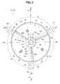
- FIG. 2 shows the airbag 30 as seen from the front side of the vehicle 10.
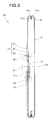
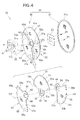
- the airbag device 20, as shown in FIGS. 3 and 4 is composed of the inflator 21, a retainer 22, a fixing ring 23, and the airbag 30, which are shown by the imaginary lines.
- the inflator 21 When the inflator 21 receives an ignite signal from a controller (not shown) due to collision energy acting on the vehicle 10, the inflator 21 ignites a gas-forming agent, whereby high-pressure gas for deploying the airbag (hereinbelow referred to simply as "gas") is generated and supplied to the airbag 30.
- the inflator 21 has a mounting flange 21a.
- the retainer 22 is a member for retaining the airbag 30 in a folded state and supporting the inflator 21, and is provided over a steering wheel 14 ( FIG. 1 ).
- the mounting flange 21a is bolted to the retainer 22, whereby the inflator 21 is fixed to a hub 14a of the steering wheel 14 shown in FIG. 1 .
- the airbag 30 is accommodated in the hub 14a of the steering wheel 14.
- the airbag 30 is composed of a rear-side sheet (a first sheet) 31 and a front-side sheet (a second sheet or a back-surface section) 41. Both the rear-side sheet 31 and the front-side sheet 41 are circular in overall shape.
- the circular airbag 30 is configured by the rear-side sheet 31 and the front-side sheet 41 overlapping each other and outer peripheral parts 31a, 41a being joined together (sewn integrally at sutured parts 42 in the outer periphery).
- the rear-side sheet 31 is the section on the front surface (the bag rear half) that faces the vehicle occupant Mn being protected, and is configured from a single base cloth.
- the front-side sheet 41 is the section on the back surface (the bag front half) that does not come in contact with the vehicle occupant Mn, i.e., a section positioned so as to face the steering wheel 14.
- the front-side sheet 41 is appropriately referred to as the "back-surface section 41.”
- the inflator insertion hole 43 is disposed in the center CP of the front-side sheet 41 (the center CP of the airbag 30, the center CP of the circle), and is a circular through-hole that encircles the inserted inflator 21.
- the gas generated by the inflator 21 is supplied into the airbag 30.
- the plurality of bolt holes 44 is disposed in the periphery around of the inflator insertion hole 43.
- the front-side sheet 41 and the fixing ring 23 are made to overlap the mounting flange 21a of the inflator 21, and bolts 24 (see FIG. 4 ) inserted through the bolt holes 44 are screwed into the mounting flange 21a, whereby the airbag 30 is mounted to the retainer 22.
- the front-side sheet 41 (the back-surface section 41) is a complex configured integrally from a plurality of divided base cloths 51 to 53.
- the front-side sheet 41 is formed by three base cloths 51 to 53.
- the plurality of base cloths 51 to 53 are arranged evenly along the sheet surface (the back surface) of the front-side sheet 41, and only the ends (the borders) 51a, 52a, 53a, which are adjacent in the circumferential direction, overlap each other.
- These overlapping sections 61 to 63 are hereinbelow referred to as "overlapping parts 61 to 63.”
- the respective overlapping parts 61 to 63 are positioned evenly in the circumferential direction with reference to the center CP of the circle.
- the point equivalent to 12:00 on a clock is designated as 0°, and the angle increases clockwise based on this point 0°.
- the plurality of base cloths 51 to 53 is appropriately referred to as the "first base cloth 51,” the “second base cloth 52,” and the “third base cloth 53.”
- the first base cloth 51 is positioned at the point 0°, and the second base cloth 52 and third base cloth 53 are positioned sequentially clockwise.
- the first overlapping part 61 is a section where an end 51a of the first base cloth 51 and an end 52a of the second base cloth 52 overlap one another front-to-back.
- the second overlapping part 62 is a section where the end 52a of the second base cloth 52 and an end 53a of the third base cloth 53 overlap one another front-to-back.
- the third overlapping part 63 is a section where the end 53a of the third base cloth 53 and the end 51a of the first base cloth 51 overlap one another front-to-back.
- the plurality of base cloths 51 to 53 are formed into a fan shape with reference to the center CP of the circle so that the front-side sheet 41 describes an overall circular shape.
- the central angles ⁇ 1 of this fan are uniform or nearly uniform.
- the overlapping angles ⁇ 2 (overlap width) of the respective overlapping parts 61 to 63, where the plurality of base cloths 51 to 53 are adjacent to each other, are uniform or nearly uniform.
- the overlapping angles ⁇ 2 are set to optimal values that take into account the ejection starting pressure, the ejection rate, and the quantity of the gas ejected to the exterior from the airbag 30.
- the first overlapping part 61 is positioned at the point 60°
- the second overlapping part 62 is positioned at the point 180°
- the third overlapping part 63 is positioned at the point 300°.
- the overlap widths of the overlapping parts 61 to 63 may be uniform, for example, rather than being set to the overlapping angles ⁇ 2.
- the base cloths constituting the rear-side sheet 31 and the plurality of base cloths 51 to 53 are all composed of cloths, i.e., flexible panels of the same material and the same thickness. These cloths have different friction characteristics (friction resistance) on the front and back sides. For example, the friction characteristics differ in the front and back sides due to a silicon coating being formed on one side of the cloth.
- the rear-side sheet 31 and the plurality of base cloths 51 to 53 face each other with the sides that have low friction resistance.
- Each of the base cloths 51 to 53 is composed of a middle circular base part 54 extending around the center CP, and a fan part 55 connected to an outer periphery of the base part 54.
- the inflator insertion hole 43 and the bolt holes 44 are opened in the middles of the base parts 54.
- the base parts 54 in the respective base cloths 51 to 53 are all made to overlap and are joined together (sewn integrally at a sutured part 45). Therefore, the strength of the inflator insertion hole 43 section in the front-side sheet 41 increases.
- the fan parts 55 each have an arcuate folding part 55a and linear folding parts 55b, 55b.
- the arcuate folding parts 55a are arcuate folding sections in which edges are formed by the arcuate edges of the fans being folded back toward the rear-side sheet 31.
- the arcuate folding parts 55a constitute the outer peripheral part 41a of the front-side sheet 41 shown in FIG. 3 .
- the linear folding parts 55b, 55b are substantially linear folding sections in which edges are formed by the edges at both circumferential ends of the fans (equivalent to the ends 51a, 52a, 53a in the circumferential direction of the plurality of base cloths 51 to 53) being folded back toward the rear-side sheet 31.
- the linear folding parts 55b, 55b are sutured so as to preserve the edged state.
- FIG. 5(a) shows an enlarged view of a second unjoined section 62a shown in FIG. 2 .
- FIG. 5(b) is an enlarged cross-sectional view taken along line b-b of FIG. 5(a) .
- At least some of the overlapping parts 61 to 63 are configured as so-called unjoined sections 61a to 63a, which are not joined together (not sewn integrally by a sutured part 65) as shown in FIGS. 2 and 5(a) and (b) .
- These unjoined sections 61a to 63a are referred to respectively as a "first unjoined section 61a,” the “second unjoined section 62a,” and a "third unjoined section 63a.”
- unjoined sections 61a to 63a are used in place of the conventionally known vent hole.
- the unjoined sections 61a to 63a are closed during the normal state in which the internal pressure of the airbag 30 is nil or low, and are opened according to the increase in internal pressure to be capable of ejecting gas when the internal pressure of the airbag 30 has reached a predetermined value.
- the unjoined sections 61a to 63a have lengths Ln, the maximum values thereof being the entire length Ls of the ends 51a, 52a, 53a in the circumferential direction of the fan parts 55, and the lengths Ln are set to optimal values that take into account the ejection starting pressure, the ejection rate, and the quantity of the gas ejected to the exterior from the airbag 30.
- the plurality of unjoined sections 61a to 63a shown in FIG. 2 are positioned evenly in the circumferential direction about the center CP of the circle, and these sections extend in a radial formation with respect to the center CP.
- spokes 14b of the steering wheel 14 are commonly positioned mostly in the bottom half of the steering wheel 14 in a steering neutral state, as shown in FIGS. 1 and 6 .
- the spokes 14b are mostly positioned in the range of the points 90° to 270°.
- the first overlapping part 61 and the first unjoined section 61a are positioned at the point 60°
- the third overlapping part 63 and the third unjoined section 63a are positioned at the point 300°, as described above.
- the plurality of unjoined sections 61a to 63a are positioned such that at least some of the unjoined sections 61a to 63a do not overlap the spokes 14b of the steering wheel 14.
- the gas Ga inside the airbag 30 when the gas Ga inside the airbag 30 is ejected to the exterior from the first and third unjoined sections 61a, 63a, the ejected gas Ga can flow into the passenger compartment 11 (see FIG. 1 ) without being blocked by the spokes 14b. Consequently, excess gas Ga inside the airbag 30 can be ejected to the exterior quickly and reliably.
- the inflator 21 shown in FIG. 3 receives an ignition signal and ignites the gas-forming agent, thereby generating gas and supplying the gas to the airbag 30.
- the airbag 30 accommodated in a folded up state on the steering wheel 14 begins to be deployed by the supplied gas.
- a cover (not shown) mounted on the steering wheel 14 ruptures from a tear line and forms an opening for the airbag 30 to project through. As a result, the airbag 30 begins to deploy into the passenger compartment 11.
- FIG. 7(a) schematically depicts the airbag 30 seen from the front side of the vehicle 10, and corresponds to FIG. 2 .
- FIG. 7(b) shows a cross section taken along line b-b of FIG. 7(a) .
- FIG. 7(c) schematically depicts the airbag 30 when it has fully deployed, and corresponds to FIG. 7(b) .
- FIG. 7(d) shows on enlarged scape the second unjoined section 62a shown in FIG. 7(c) .
- FIGS. 7(e) through 7(g) illustrate a manner which the second unjoined section 62a shown in FIG. 7(d) changes according to the increase in internal pressure pb.
- FIG. 7(h) schematically depicts the airbag 30 in the state of FIG. 7(g) .
- FIG. 7(i) shows on enlarged scape the second unjoined section 62a while opening in the state of FIG. 7(h) .
- the internal pressure pb increases, the plurality of base cloths 51 to 53 are pulled in the circumferential direction (in the direction of the arrows Te, Te) about the center CP of the circle, along the surface of the front-side sheet 41.
- the internal pressure pb of the airbag 30 at this state of deployment completion is comparatively low. Since the pressure difference between the inside and outside of the airbag 30 is small, the unjoined sections 61a to 63a are closed as shown in FIGS. 7(c) and (d) . Therefore, there is a small leakage quantity of gas Ga inside the airbag 30 leaking out to the exterior from the unjoined sections 61a to 63a. In other words, merely with the airbag deployed, the internal pressure pb does not reach a certain reference pressure set in advance. Therefore, the airbag 30 essentially preserves its deployed shape.
- the vehicle occupant Mn shown in FIG. 1 then collides with the airbag 30 (a secondary collision).
- the airbag 30 changes shape due to the vehicle occupant Mn colliding.
- the internal pressure pb of the airbag 30 further increases. Due to the internal pressure pb increasing to a reference pressure, the plurality of base cloths 51 to 53 are further pulled in the circumferential direction about the center CP of the circle, along the surface of the front-side sheet 41.
- the plurality of base cloths 51 to 53 is further pulled in the circumferential direction about the center CP of the circle, along the surface of the front-side sheet 41.
- the overlap widths ⁇ 2 of the overlapping parts 61 to 63 in the unjoined sections 61a to 63a are reduced by the pulling action in the circumferential direction about the center CP of the circle. In other words, the overlap widths ⁇ 2 shift so as to decrease in the sequence shown in FIGS. 7(e) and (f).
- the unjoined sections 61a to 63a are then completely opened as shown in FIGS. 7(g) and (h) .
- the unjoined sections 61a to 63a essentially begin to open from the stage in which the vehicle occupant Mn (the protected object Mn) collides with the deployed airbag 30.
- the unjoined sections 61a to 63a open in the sequence of FIG. 7(f) and FIG. 7(g) , and the excess gas Ga inside the airbag 30 is ejected to the exterior.
- FIG. 7(h) and FIG. 7(i) represent a state in which a large quantity of excess gas Ga inside the airbag 30 is ejected by the unjoined sections 61a to 63a opening by a large amount.
- the pulling action in the circumferential direction about the center CP of the circle can be effectively utilized to begin to reliably open the unjoined sections 61a to 63a with the proper timing.
- the ejection timing, the ejection rate, and the ejected quantity of the gas Ga ejected to the exterior from the unjoined sections 61a to 63a can be precisely set according to the collision mode of the vehicle occupant Mn (the protected object Mn) colliding with the deployed airbag 30.
- the collision mode of the vehicle occupant Mn the protected object Mn
- the first collision mode is a mode in which the head Hd of the vehicle occupant Mn collides with the top end part (the outer peripheral section) of the airbag 30 deployed as shown in FIG. 1 .
- the head Hd collides with the outer peripheral section of the airbag 30 in a so-called radial direction from radially outward toward the center (in the direction of arrow Fs), when the airbag 30 having been deployed into the passenger compartment 11 is viewed from the vehicle occupant Mn side, as shown in FIG. 1 , for example.
- the shape of the airbag 30 readily collapses (or deforms) locally due to the collision energy (the secondary collision energy) when the head Hd collides with the airbag 30.
- the force whereby the base cloths 51 to 53 are pulled in the direction of the arrows Te, Te increases, as shown in FIG. 7 . Therefore, some of the unjoined sections 61a to 63a locally open readily, and the ejected quantity of the gas Ga ejected to the exterior from the unjoined sections 61a to 63a therefore increases.
- a large quantity of the gas Ga is quickly ejected and the secondary collision energy is sufficiently absorbed, whereby a large amount of secondary collision energy inflicted on the vehicle occupant Mn can be sufficiently alleviated.
- the chest Ch of the vehicle occupant Mn collides with the front surface of the airbag 30 deployed as shown in FIG. 1 .
- the shape of the airbag 30 is preserved comparatively readily despite the secondary collision energy. Since the unjoined sections 61a to 63a open less readily than in the case of the first collision mode, the ejected quantity of the gas Ga ejected to the exterior from the unjoined sections 61a to 63a is smaller. Due to the smaller ejected quantity, a large amount of secondary collision energy can be sufficiently absorbed by the entire airbag 30.
- At least one value among the number of unjoined sections 61a to 63a, the overlap widths ⁇ 2 of the overlapping parts 61 to 63 in the unjoined sections 61a to 63a, and the lengths Ln of the unjoined sections 61a to 63a is set such that from the stage in which the airbag 30 expands and begins to contact the vehicle occupant Mn (the protected object Mn), the unjoined sections 61a to 63a begin to open according to the increase in the internal pressure pb of the airbag 30.
- the plurality of base cloths 51 to 53 constituting the back surface of the airbag 30 is arranged along the back surface and only the adjacent ends 51a, 52a, 53a overlap each other, constituting the overlapping parts 61 to 63. At least some of the overlapping parts 61 to 63 are configured as unjoined sections 61a to 63a which are not joined together.
- the ejection timing, the ejection rate, and the ejected quantity of the gas Ga ejected to the exterior from the unjoined sections 61a to 63a can be precisely controlled in accordance with the collision mode of the vehicle occupant Mn against the deployed airbag 30.
- the overlap widths ⁇ 2 and the lengths Ln of the unjoined sections 61a to 63a may be set to separate values with each of the respective unjoined sections 61a, 62a, and 63a.
- FIG. 8 shows the configuration of an airbag 30A of the second embodiment, seen from the front side of the vehicle 10 ( FIG. 1 ).
- a front-side sheet 41A is formed by two base cloths 51A, 52A.
- the first base cloth 51A and the second base cloth 52A are set in essentially the same size.
- the base cloths 51A, 52A have essentially the same configuration as the base cloths 51, 52 of the first embodiment.
- First and second overlapping parts 61A, 62A have the same configuration as the first and second overlapping parts 61, 62 of the first embodiment.
- the overlap widths Wr of the overlapping parts 61A, 62A have a certain width.
- First and second unjoined sections 61aA, 62aA have the same configuration as the first and second unjoined sections 61a, 62a of the first embodiment.
- the first overlapping part 61A and the second overlapping part 62A are positioned in point symmetry with each other with respect to the center CP.
- the first overlapping part 61A and the first unjoined section 61aA are positioned at the point 165°
- the second overlapping part 62A and the second unjoined section 62aA are positioned at the point 345°.
- the airbag 30A of the second embodiment having this configuration exhibits the same operation and effects as the airbag 30 of the first embodiment. Furthermore, when the gas Ga inside the airbag 30A is ejected to the exterior from the first and second unjoined sections 61aA, 62aA, the ejected gas Ga can flow into the passenger compartment 11 ( FIG. 1 ) while being mostly unblocked by the spokes 14b. Consequently, the excess gas Ga inside the airbag 30A can be quickly and reliably ejected to the exterior.
- the unjoined sections 61a to 63a are preferably configured on at least some of the plurality of overlapping parts 61 to 63.
- the configuration may be one in which the first unjoined section 61a is provided in the first overlapping part 61 and the third unjoined section 63a is provided in the third overlapping part 63, but an unjoined section is not provided in the second overlapping part 62.
- unjoined sections 61aA to 63aA are preferably configured on at least some of the plurality of overlapping parts 61A, 62A.
- the airbags 30, 30A of the present invention are suitable for use in the vehicle airbag device 20 for restraining and protecting a vehicle occupant Mn sitting in the driver seat 12 or the passenger seat 13 of the vehicle 10 by deploying in front of the vehicle occupant Mn. Furthermore, the airbags 30, 30A of the present invention are suitable for use as side airbags for restraining and protecting a vehicle occupant Mn sitting in the passenger compartment 11 by deploying to the side of the vehicle occupant Mn. Furthermore, the airbags 30, 30A of the present invention are suitable for use as pedestrian-protecting airbags for protecting pedestrians by being provided to the hood of the vehicle 10, for example, and deploying to the vehicle exterior. Reference Signs List
Landscapes
- Engineering & Computer Science (AREA)
- Mechanical Engineering (AREA)
- Air Bags (AREA)
Abstract
Description
- The present invention relates to an airbag adapted for deployment by gas generated by an inflator, and particularly relates to a vehicle airbag.
- When collision energy acts on a vehicle, for example, a vehicle airbag deploys in front of a vehicle occupant sitting in a driver seat or a passenger seat, thereby protecting the vehicle occupant.
- Airbags of the type described have a vent hole. The vent hole is a gas-releasing hole through which some of the gas is ejected to the exterior so as to restrict excessive increases in internal pressure when the airbag is deployed. The size of the vent hole is set in advance and does not change. Therefore, the ejection rate or quantity of gas ejected to the exterior from the vent hole cannot be precisely controlled in accordance with the state in which a vehicle occupant collides with the deployed airbag.
- From an initial stage in which the airbag begins to deploy in front of the vehicle occupant, the gas inside the airbag begins to be ejected to the exterior through the vent hole. To increase the airbag's performance of protecting the vehicle occupant, it is preferable that the internal pressure of the airbag be maintained over a long period of time. However, the ejection rate and quantity of the gas ejected to the exterior from the vent hole cannot be controlled.
- Thus, an improvement can be made in regard to merely having a vent hole in the airbag, in terms of precisely controlling the internal pressure of the airbag. In view whereof, techniques for controlling the internal pressure of an airbag have recently been developed (see Patent Document 1, for example).
- The airbag taught in Patent Document 1 has a vent hole cover for closing the vent hole. This vent hole cover comprises a plurality of sewn parts sewn into the airbag. The sewn parts sequentially rupture as the internal pressure increases when the airbag is deployed, and the rupturing concludes at the end of the airbag deployment. As a result, the vent hole cover is removed from the vent hole, and therefore the vent hole is opened. In other words, it is possible to control the timing with which the gas inside the airbag is ejected to the exterior from the vent hole.
- However, in the airbag known in Patent Document 1, the size of the vent hole is set in advance and does not change. Therefore, the ejection timing, ejection rate, and quantity of the gas ejected to the exterior from the opened vent hole cannot be precisely controlled in accordance with the state in which the vehicle occupant collides with the deployed airbag. Moreover, in the airbag known in Patent Document 1, since the vent hole cover for closing the vent hole is sewn, controlling the ejection timing, ejection rate, and ejected quantity of the gas in accordance with the state in which the vehicle occupant collides with the deployed airbag inevitably makes the configuration complicated and causes cost to increase.
-
- [Patent Document 1] Japanese Patent Application Laid-Open Publication No.
2007-302224 - An object of the present invention is to provide a technique whereby the ejection timing, ejection rate, and quantity of a gas ejected to the exterior from an airbag can be precisely controlled.
- According to the invention, as defined in claim 1, there is provided an airbag comprising a first sheet near a protected object, and a second sheet far from the protected object, wherein outer peripheral parts of the first sheet and the second sheet are joined, characterized in that the second sheet is formed by a plurality of divided base cloths, the base cloths are arrayed along a circumferential direction and have overlapping parts where adjacent ends are overlapping, at least some of the overlapping parts have unjoined sections not joined together, and when the airbag deploys and the protected object collides therewith, a gas can be ejected through the unjoined sections.
- In the invention, as defined in claim 2, preferably, the second sheet is circular in overall shape, each of the base cloths is formed into a fan shape with reference to a center of the circular second sheet, and the unjoined sections extend in a radial direction with reference to the center of the circular second sheet.
- In the invention, as defined in
claim 3, preferably, at least one value among the number of the unjoined sections, an overlap width of the overlapping parts in the unjoined sections, and a length of the unjoined sections is set such that the unjoined sections begin to open from a stage in which the protected object collides with the deployed airbag. - In the invention, as defined in claim 4, preferably, the airbag of the second aspect is accommodated in a hub of a vehicle steering wheel, and the unjoined sections are positioned such that at least some of the unjoined sections do not overlap a spoke of the vehicle steering wheel when the airbag deployed in a passenger compartment is viewed from a front side of the vehicle.
- In the invention, as defined in claim 5, preferably, the unjoined sections are plural in number, and the plural unjoined sections are positioned evenly in the circumferential direction with reference to the center of the circular second sheet.
- In the invention, as defined in claim 1, the plurality of base cloths is arrayed along the circumferential direction and adjacent ends overlap, constituting the overlapping parts. At least some of the overlapping parts are configured as a plurality of unjoined sections which are not joined together. These unjoined sections can be set so as to not open at the internal pressure at the time the airbag has completely deployed. Therefore, the airbag can essentially preserve the deployed shape.
- When the protected object (the vehicle occupant) collides with the deployed airbag, the airbag deforms, whereby the unjoined sections open and excess gas inside the airbag can be ejected to the exterior. Therefore, the ejection timing, the ejection rate, and the quantity of the gas ejected to the exterior from the unjoined sections can be precisely set (controlled) in accordance with the collision mode of the protected object against the deployed airbag. Moreover, in order for the ejection timing, the ejection rate, and the ejected quantity to be set according to the airbag, the configuration is simple, merely in which at least some of the overlapping parts of the plurality of base cloths are not joined. Examples of the collision mode include a first collision mode in which the protected object collides with an outer peripheral part of the deployed airbag, and a second collision mode in which the protected object collides with a front surface of the deployed airbag.
- In the invention, as defined in claim 2, the plurality of unjoined sections extends in the radial direction with reference to the center of the circular second sheet. The shape of the airbag is changed by the colliding protected object. As the shape changes, the plurality of base cloths is pulled in the circumferential direction about the center, along the surface of the second sheet. Since the unjoined sections extend in the radial direction with reference to the center, the pulling action in the circumferential direction about the center can be effectively utilized to begin to reliably open the unjoined sections with the proper timing.
- In the invention, as defined in
claim 3, due to at least one value among the number of the unjoined sections, the overlap width of the overlapping parts in the unjoined sections, and the lengths of the unjoined sections being set in advance, the unjoined sections begin to open from the stage in which the protected object collides with the deployed airbag. Thus, the ejection timing, the ejection rate, and the quantity of the gas ejected to the exterior from the unjoined sections can be precisely set in accordance with the collision mode of the protected object against the deployed airbag. - In the invention, as defined in claim 4, the unjoined sections are positioned such that at least some of the unjoined sections do not overlap the spoke of the steering wheel when the airbag deployed in the passenger compartment is viewed from the front side of the vehicle. Therefore, when the gas inside the airbag is ejected to the exterior from the unjoined sections, the ejected gas can flow into the passenger compartment without being blocked by the spoke. Consequently, excess gas inside the airbag can be quickly and reliably ejected to the exterior.
- In the invention, as defined in claim 5, the unjoined sections are plurality in number. The plural unjoined sections are positioned evenly in the circumferential direction about the center of the circular back surface section. Therefore, the positional relationship of the plural unjoined sections to the steering wheel does not change regardless of the steering state of the steering wheel, and the unjoined sections are also positioned evenly in the circumferential direction relative to the steering wheel. Consequently, no matter what area of the deployed airbag the protected object collides with, the shape of the airbag locally collapses (or deforms) readily. As a result, some of the unjoined sections locally open readily, and ejection of the gas is begun readily.
-
-
FIG. 1 is a perspective view showing the interior of a vehicle equipped with an airbag according to a first embodiment of the present invention; -
FIG. 2 is a view of an enlarged configuration of the airbag shown inFIG. 1 , as seen from the front side of the vehicle; -
FIG. 3 is a cross-sectional view taken along line 3-3 ofFIG. 2 ; -
FIG. 4 is an exploded view of the airbag shown inFIG. 3 ; -
FIG. 5(a) is a view illustrating a configuration of a second unjoined section ofFIG. 2 ; -
FIG. 5(b) is a cross-sectional view taken along line b-b ofFIG. 5(a) ; -
FIG. 6 is a view showing the relationship between a steering wheel and the airbag shown inFIG. 2 ; -
FIGS. 7(a) through 7(i) are views illustrative of the operation of the airbag shown inFIG. 2 ; and -
FIG. 8 is a view of an enlarged configuration of an airbag according to a second embodiment of the present invention as seen from the front side of the vehicle. - Certain preferred embodiments of the present invention will be described below with reference to the accompanying sheets of drawings.
- As shown in
FIG., 1 , avehicle 10 is equipped with anairbag device 20. When collision energy acts on thevehicle 10, theairbag device 20 causes anairbag 30 to be deployed into apassenger compartment 11 by high-pressure gas generated by an inflator 21 (seeFIGS. 3 and4 ). Theairbag 30 is deployed in front of a vehicle occupant Mn sitting in adriver seat 12, apassenger seat 13, or another seat such as rear seat (not shown), and theairbag 30 protects the vehicle occupant Mn by restraining the vehicle occupant Mn. In the present embodiment, a device for protecting a vehicle occupant Mn (a driver Mn) sitting in thedriver seat 12 is described as an example of theairbag device 20. - The
airbag device 20 is described hereinbelow in detail.FIG. 2 shows theairbag 30 as seen from the front side of thevehicle 10. Theairbag device 20, as shown inFIGS. 3 and4 , is composed of the inflator 21, aretainer 22, a fixingring 23, and theairbag 30, which are shown by the imaginary lines. - When the inflator 21 receives an ignite signal from a controller (not shown) due to collision energy acting on the
vehicle 10, theinflator 21 ignites a gas-forming agent, whereby high-pressure gas for deploying the airbag (hereinbelow referred to simply as "gas") is generated and supplied to theairbag 30. The inflator 21 has a mountingflange 21a. Theretainer 22 is a member for retaining theairbag 30 in a folded state and supporting the inflator 21, and is provided over a steering wheel 14 (FIG. 1 ). The mountingflange 21a is bolted to theretainer 22, whereby the inflator 21 is fixed to ahub 14a of thesteering wheel 14 shown inFIG. 1 . As a result, theairbag 30 is accommodated in thehub 14a of thesteering wheel 14. - The
airbag 30 is composed of a rear-side sheet (a first sheet) 31 and a front-side sheet (a second sheet or a back-surface section) 41. Both the rear-side sheet 31 and the front-side sheet 41 are circular in overall shape. Thecircular airbag 30 is configured by the rear-side sheet 31 and the front-side sheet 41 overlapping each other and outerperipheral parts parts 42 in the outer periphery). - When the
airbag 30 is deployed into thepassenger compartment 11 as shown inFIG. 1 , the rear-side sheet 31 is the section on the front surface (the bag rear half) that faces the vehicle occupant Mn being protected, and is configured from a single base cloth. - When the
airbag 30 is deployed into thepassenger compartment 11 as shown inFIG. 1 , the front-side sheet 41 is the section on the back surface (the bag front half) that does not come in contact with the vehicle occupant Mn, i.e., a section positioned so as to face thesteering wheel 14. Hereinbelow, the front-side sheet 41 is appropriately referred to as the "back-surface section 41." - Formed in the front-
side sheet 41 are oneinflator insertion hole 43 and a plurality of bolt holes 44. Theinflator insertion hole 43 is disposed in the center CP of the front-side sheet 41 (the center CP of theairbag 30, the center CP of the circle), and is a circular through-hole that encircles the insertedinflator 21. The gas generated by theinflator 21 is supplied into theairbag 30. - The plurality of bolt holes 44 is disposed in the periphery around of the
inflator insertion hole 43. The front-side sheet 41 and the fixingring 23 are made to overlap the mountingflange 21a of the inflator 21, and bolts 24 (seeFIG. 4 ) inserted through the bolt holes 44 are screwed into the mountingflange 21a, whereby theairbag 30 is mounted to theretainer 22. - The front-side sheet 41 (the back-surface section 41) is a complex configured integrally from a plurality of divided
base cloths 51 to 53. In the illustrated first embodiment, the front-side sheet 41 is formed by threebase cloths 51 to 53. The plurality ofbase cloths 51 to 53 are arranged evenly along the sheet surface (the back surface) of the front-side sheet 41, and only the ends (the borders) 51a, 52a, 53a, which are adjacent in the circumferential direction, overlap each other. These overlappingsections 61 to 63 are hereinbelow referred to as "overlappingparts 61 to 63." The respective overlappingparts 61 to 63 are positioned evenly in the circumferential direction with reference to the center CP of the circle. - When the deployed
airbag 30 is viewed from the front side of thevehicle 10 as shown inFIG. 2 , with reference to the center CP of the circle, the point equivalent to 12:00 on a clock is designated as 0°, and the angle increases clockwise based on this point 0°. The plurality ofbase cloths 51 to 53 is appropriately referred to as the "first base cloth 51," the "second base cloth 52," and the "third base cloth 53." Thefirst base cloth 51 is positioned at the point 0°, and thesecond base cloth 52 andthird base cloth 53 are positioned sequentially clockwise. - The first overlapping
part 61 is a section where anend 51a of thefirst base cloth 51 and anend 52a of thesecond base cloth 52 overlap one another front-to-back. The second overlappingpart 62 is a section where theend 52a of thesecond base cloth 52 and anend 53a of thethird base cloth 53 overlap one another front-to-back. The third overlappingpart 63 is a section where theend 53a of thethird base cloth 53 and theend 51a of thefirst base cloth 51 overlap one another front-to-back. - To be more specific, the plurality of
base cloths 51 to 53 are formed into a fan shape with reference to the center CP of the circle so that the front-side sheet 41 describes an overall circular shape. The central angles θ1 of this fan are uniform or nearly uniform. The overlapping angles θ2 (overlap width) of the respective overlappingparts 61 to 63, where the plurality ofbase cloths 51 to 53 are adjacent to each other, are uniform or nearly uniform. - The overlapping angles θ2 are set to optimal values that take into account the ejection starting pressure, the ejection rate, and the quantity of the gas ejected to the exterior from the
airbag 30. The first overlappingpart 61 is positioned at the point 60°, the second overlappingpart 62 is positioned at the point 180°, and the third overlappingpart 63 is positioned at thepoint 300°. - The overlap widths of the overlapping
parts 61 to 63 may be uniform, for example, rather than being set to the overlapping angles θ2. - The base cloths constituting the rear-
side sheet 31 and the plurality ofbase cloths 51 to 53 are all composed of cloths, i.e., flexible panels of the same material and the same thickness. These cloths have different friction characteristics (friction resistance) on the front and back sides. For example, the friction characteristics differ in the front and back sides due to a silicon coating being formed on one side of the cloth. The rear-side sheet 31 and the plurality ofbase cloths 51 to 53 face each other with the sides that have low friction resistance. - The base cloths 51 to 53 will be described in greater detail. Each of the
base cloths 51 to 53 is composed of a middlecircular base part 54 extending around the center CP, and afan part 55 connected to an outer periphery of thebase part 54. Theinflator insertion hole 43 and the bolt holes 44 are opened in the middles of thebase parts 54. Thebase parts 54 in therespective base cloths 51 to 53 are all made to overlap and are joined together (sewn integrally at a sutured part 45). Therefore, the strength of theinflator insertion hole 43 section in the front-side sheet 41 increases. - The
fan parts 55 each have anarcuate folding part 55a and linearfolding parts arcuate folding parts 55a are arcuate folding sections in which edges are formed by the arcuate edges of the fans being folded back toward the rear-side sheet 31. Thearcuate folding parts 55a constitute the outerperipheral part 41a of the front-side sheet 41 shown inFIG. 3 . Thelinear folding parts ends base cloths 51 to 53) being folded back toward the rear-side sheet 31. Thelinear folding parts -
FIG. 5(a) shows an enlarged view of a secondunjoined section 62a shown inFIG. 2 .FIG. 5(b) is an enlarged cross-sectional view taken along line b-b ofFIG. 5(a) . - At least some of the overlapping
parts 61 to 63 are configured as so-calledunjoined sections 61a to 63a, which are not joined together (not sewn integrally by a sutured part 65) as shown inFIGS. 2 and 5(a) and (b) . Theseunjoined sections 61a to 63a are referred to respectively as a "firstunjoined section 61a," the "secondunjoined section 62a," and a "thirdunjoined section 63a." - These
unjoined sections 61a to 63a are used in place of the conventionally known vent hole. Theunjoined sections 61a to 63a are closed during the normal state in which the internal pressure of theairbag 30 is nil or low, and are opened according to the increase in internal pressure to be capable of ejecting gas when the internal pressure of theairbag 30 has reached a predetermined value. Theunjoined sections 61a to 63a have lengths Ln, the maximum values thereof being the entire length Ls of theends fan parts 55, and the lengths Ln are set to optimal values that take into account the ejection starting pressure, the ejection rate, and the quantity of the gas ejected to the exterior from theairbag 30. - The plurality of
unjoined sections 61a to 63a shown inFIG. 2 are positioned evenly in the circumferential direction about the center CP of the circle, and these sections extend in a radial formation with respect to the center CP. - It is known that
spokes 14b of thesteering wheel 14 are commonly positioned mostly in the bottom half of thesteering wheel 14 in a steering neutral state, as shown inFIGS. 1 and6 . In other words, thespokes 14b are mostly positioned in the range of the points 90° to 270°. Accordingly, the first overlappingpart 61 and the firstunjoined section 61a are positioned at the point 60°, and the third overlappingpart 63 and the thirdunjoined section 63a are positioned at thepoint 300°, as described above. Therefore, when theairbag 30 deployed in thepassenger compartment 11 is viewed from the back surface, the plurality ofunjoined sections 61a to 63a are positioned such that at least some of theunjoined sections 61a to 63a do not overlap thespokes 14b of thesteering wheel 14. - Therefore, when the gas Ga inside the
airbag 30 is ejected to the exterior from the first and thirdunjoined sections FIG. 1 ) without being blocked by thespokes 14b. Consequently, excess gas Ga inside theairbag 30 can be ejected to the exterior quickly and reliably. - Next, the operation of the
airbag device 20 according to the first embodiment will be described. - When at least a predetermined amount of collision energy acts on the vehicle 10 (see
FIG. 1 ), the inflator 21 shown inFIG. 3 receives an ignition signal and ignites the gas-forming agent, thereby generating gas and supplying the gas to theairbag 30. Theairbag 30 accommodated in a folded up state on the steering wheel 14 (seeFIG. 1 ) begins to be deployed by the supplied gas. During the process of theairbag 30 deploying, a cover (not shown) mounted on thesteering wheel 14 ruptures from a tear line and forms an opening for theairbag 30 to project through. As a result, theairbag 30 begins to deploy into thepassenger compartment 11. -
FIG. 7(a) schematically depicts theairbag 30 seen from the front side of thevehicle 10, and corresponds toFIG. 2 . -
FIG. 7(b) shows a cross section taken along line b-b ofFIG. 7(a) . -
FIG. 7(c) schematically depicts theairbag 30 when it has fully deployed, and corresponds toFIG. 7(b) . -
FIG. 7(d) shows on enlarged scape the secondunjoined section 62a shown inFIG. 7(c) . -
FIGS. 7(e) through 7(g) illustrate a manner which the secondunjoined section 62a shown inFIG. 7(d) changes according to the increase in internal pressure pb. -
FIG. 7(h) schematically depicts theairbag 30 in the state ofFIG. 7(g) . -
FIG. 7(i) shows on enlarged scape the secondunjoined section 62a while opening in the state ofFIG. 7(h) . - During the initial state shown in
FIG. 7(a) and (b) , when gas begins to be supplied from the inflator 21 (FIG. 3 ) to theairbag 30, theairbag 30 deploys as the supplied gas quantity increases, and as a result, deployment into the passenger compartment 11 (FIG. 1 ) completes as shown inFIG. 7(c) . - As the internal pressure pb increases, the plurality of
base cloths 51 to 53 are pulled in the circumferential direction (in the direction of the arrows Te, Te) about the center CP of the circle, along the surface of the front-side sheet 41. However, the internal pressure pb of theairbag 30 at this state of deployment completion is comparatively low. Since the pressure difference between the inside and outside of theairbag 30 is small, theunjoined sections 61a to 63a are closed as shown inFIGS. 7(c) and (d) . Therefore, there is a small leakage quantity of gas Ga inside theairbag 30 leaking out to the exterior from theunjoined sections 61a to 63a. In other words, merely with the airbag deployed, the internal pressure pb does not reach a certain reference pressure set in advance. Therefore, theairbag 30 essentially preserves its deployed shape. - The vehicle occupant Mn shown in
FIG. 1 then collides with the airbag 30 (a secondary collision). Theairbag 30 changes shape due to the vehicle occupant Mn colliding. As a result, the internal pressure pb of theairbag 30 further increases. Due to the internal pressure pb increasing to a reference pressure, the plurality ofbase cloths 51 to 53 are further pulled in the circumferential direction about the center CP of the circle, along the surface of the front-side sheet 41. Moreover, along with the shape change in theairbag 30, the plurality ofbase cloths 51 to 53 is further pulled in the circumferential direction about the center CP of the circle, along the surface of the front-side sheet 41. - Since the plurality of
unjoined sections 61a to 63a extends in a radial formation with respect to the center CP of the circle, the overlap widths θ2 of the overlappingparts 61 to 63 in theunjoined sections 61a to 63a are reduced by the pulling action in the circumferential direction about the center CP of the circle. In other words, the overlap widths θ2 shift so as to decrease in the sequence shown inFIGS. 7(e) and (f). Theunjoined sections 61a to 63a are then completely opened as shown inFIGS. 7(g) and (h) . - Thus, the
unjoined sections 61a to 63a essentially begin to open from the stage in which the vehicle occupant Mn (the protected object Mn) collides with the deployedairbag 30. In other words, theunjoined sections 61a to 63a open in the sequence ofFIG. 7(f) and FIG. 7(g) , and the excess gas Ga inside theairbag 30 is ejected to the exterior.FIG. 7(h) and FIG. 7(i) represent a state in which a large quantity of excess gas Ga inside theairbag 30 is ejected by theunjoined sections 61a to 63a opening by a large amount. Due to the excess gas Ga being ejected to the exterior from theunjoined sections 61a to 63a, excessive increases in the internal pressure pb of theairbag 30 are prevented. As a result, the collision energy when the vehicle occupant Mn collides with theairbag 30 can be efficiently alleviated. - Moreover, since the plurality of
unjoined sections 61a to 63a extend in a radial formation with respect to the center CP of the circle, the pulling action in the circumferential direction about the center CP of the circle can be effectively utilized to begin to reliably open theunjoined sections 61a to 63a with the proper timing. - Furthermore, according to the first embodiment, the ejection timing, the ejection rate, and the ejected quantity of the gas Ga ejected to the exterior from the
unjoined sections 61a to 63a can be precisely set according to the collision mode of the vehicle occupant Mn (the protected object Mn) colliding with the deployedairbag 30. There can be considered, for example, a first collision mode and a second collision mode. - The first collision mode is a mode in which the head Hd of the vehicle occupant Mn collides with the top end part (the outer peripheral section) of the
airbag 30 deployed as shown inFIG. 1 . In this mode, the head Hd collides with the outer peripheral section of theairbag 30 in a so-called radial direction from radially outward toward the center (in the direction of arrow Fs), when theairbag 30 having been deployed into thepassenger compartment 11 is viewed from the vehicle occupant Mn side, as shown inFIG. 1 , for example. - In the case of the first collision mode, the shape of the
airbag 30 readily collapses (or deforms) locally due to the collision energy (the secondary collision energy) when the head Hd collides with theairbag 30. As a result, the force whereby thebase cloths 51 to 53 are pulled in the direction of the arrows Te, Te increases, as shown inFIG. 7 . Therefore, some of theunjoined sections 61a to 63a locally open readily, and the ejected quantity of the gas Ga ejected to the exterior from theunjoined sections 61a to 63a therefore increases. A large quantity of the gas Ga is quickly ejected and the secondary collision energy is sufficiently absorbed, whereby a large amount of secondary collision energy inflicted on the vehicle occupant Mn can be sufficiently alleviated. - In the second collision mode, the chest Ch of the vehicle occupant Mn collides with the front surface of the
airbag 30 deployed as shown inFIG. 1 . In the case of the second collision mode, the shape of theairbag 30 is preserved comparatively readily despite the secondary collision energy. Since theunjoined sections 61a to 63a open less readily than in the case of the first collision mode, the ejected quantity of the gas Ga ejected to the exterior from theunjoined sections 61a to 63a is smaller. Due to the smaller ejected quantity, a large amount of secondary collision energy can be sufficiently absorbed by theentire airbag 30. - Thus, at least one value among the number of
unjoined sections 61a to 63a, the overlap widths θ2 of the overlappingparts 61 to 63 in theunjoined sections 61a to 63a, and the lengths Ln of theunjoined sections 61a to 63a is set such that from the stage in which theairbag 30 expands and begins to contact the vehicle occupant Mn (the protected object Mn), theunjoined sections 61a to 63a begin to open according to the increase in the internal pressure pb of theairbag 30. - As is clear from the above description, in the first embodiment, the plurality of
base cloths 51 to 53 constituting the back surface of theairbag 30 is arranged along the back surface and only theadjacent ends parts 61 to 63. At least some of the overlappingparts 61 to 63 are configured asunjoined sections 61a to 63a which are not joined together. - The ejection timing, the ejection rate, and the ejected quantity of the gas Ga ejected to the exterior from the
unjoined sections 61a to 63a can be precisely controlled in accordance with the collision mode of the vehicle occupant Mn against the deployedairbag 30. - The overlap widths θ2 and the lengths Ln of the
unjoined sections 61a to 63a may be set to separate values with each of the respectiveunjoined sections - An airbag according to a second embodiment of the present invention will next be described.
FIG. 8 shows the configuration of anairbag 30A of the second embodiment, seen from the front side of the vehicle 10 (FIG. 1 ). - In the
airbag 30A according to the second embodiment, a front-side sheet 41A is formed by twobase cloths first base cloth 51A and thesecond base cloth 52A are set in essentially the same size. The base cloths 51A, 52A have essentially the same configuration as thebase cloths - First and second overlapping
parts parts parts unjoined sections - The first overlapping
part 61A and the second overlappingpart 62A are positioned in point symmetry with each other with respect to the center CP. For example, the first overlappingpart 61A and the first unjoined section 61aA are positioned at the point 165°, and the second overlappingpart 62A and the second unjoined section 62aA are positioned at the point 345°. - The
airbag 30A of the second embodiment having this configuration exhibits the same operation and effects as theairbag 30 of the first embodiment. Furthermore, when the gas Ga inside theairbag 30A is ejected to the exterior from the first and second unjoined sections 61aA, 62aA, the ejected gas Ga can flow into the passenger compartment 11 (FIG. 1 ) while being mostly unblocked by thespokes 14b. Consequently, the excess gas Ga inside theairbag 30A can be quickly and reliably ejected to the exterior. - In first embodiment, the
unjoined sections 61a to 63a are preferably configured on at least some of the plurality of overlappingparts 61 to 63. For example, the configuration may be one in which the firstunjoined section 61a is provided in the first overlappingpart 61 and the thirdunjoined section 63a is provided in the third overlappingpart 63, but an unjoined section is not provided in the second overlappingpart 62. Similarly, in the second embodiment, unjoined sections 61aA to 63aA are preferably configured on at least some of the plurality of overlappingparts - The
airbags vehicle airbag device 20 for restraining and protecting a vehicle occupant Mn sitting in thedriver seat 12 or thepassenger seat 13 of thevehicle 10 by deploying in front of the vehicle occupant Mn. Furthermore, theairbags passenger compartment 11 by deploying to the side of the vehicle occupant Mn. Furthermore, theairbags vehicle 10, for example, and deploying to the vehicle exterior. Reference Signs List - 10
- Vehicle
- 14
- Steering wheel
- 14a
- Hub
- 14b
- Spoke
- 30, 30A
- Airbags
- 31
- Rear-side sheet (first sheet)
- 41
- Front-side sheet (second sheet)
- 51-53, 51A, 52A
- Plurality of base cloths
- 61-63, 61A, 62A
- Overlapping parts
- 61a-63a, 61aA, 62aA
- Unjoined sections
- CP
- Center of circular back surface
- Ln
- Length of unjoined section
- Mn
- Protected object (vehicle occupant)
- pb
- Internal pressure of airbag
- Wr, θ2
- Overlap width
Claims (5)
- An airbag comprising a first sheet near a protected object, and a second sheet far from the protected object, wherein outer peripheral parts of the first sheet and the second sheet are joined, characterized in that:the second sheet is formed by a plurality of divided base cloths;the base cloths are arrayed along a circumferential direction and have overlapping parts where adjacent ends are overlapping;at least some of the overlapping parts have unjoined sections not joined together; andwhen the airbag deploys and the protected object collides therewith, a gas can be ejected through the unjoined sections.
- The airbag of claim 1, wherein the second sheet is circular in overall shape,
each of the base cloths is formed into a fan shape with reference to a center of the circular second sheet, and
the unjoined sections extend in a radial direction with reference to the center of the circular second sheet. - The airbag of claim 1, wherein at least one value among the number of the unjoined sections, an overlap width of the overlapping parts in the unjoined sections, and a length of the unjoined sections is set such that the unjoined sections begin to open from a stage in which the protected object collides with the deployed airbag.
- The airbag of claim 2, wherein the airbag is accommodated in a hub (14a) of a vehicle steering wheel, and
the unjoined sections are positioned such that at least some of the unjoined sections do not overlap a spoke of the vehicle steering wheel when the airbag deployed in a passenger compartment is viewed from a front side of the vehicle. - The airbag of claim 4, wherein the unjoined sections are plural in number and the plural unjoined sections are positioned evenly in the circumferential direction with reference to the center of the circular second sheet.
Applications Claiming Priority (2)
| Application Number | Priority Date | Filing Date | Title |
|---|---|---|---|
| JP2010016887 | 2010-01-28 | ||
| PCT/JP2010/070109 WO2011092923A1 (en) | 2010-01-28 | 2010-11-11 | Airbag |
Publications (3)
| Publication Number | Publication Date |
|---|---|
| EP2492154A1 true EP2492154A1 (en) | 2012-08-29 |
| EP2492154A4 EP2492154A4 (en) | 2013-04-03 |
| EP2492154B1 EP2492154B1 (en) | 2013-09-18 |
Family
ID=44318924
Family Applications (1)
| Application Number | Title | Priority Date | Filing Date |
|---|---|---|---|
| EP10844677.4A Not-in-force EP2492154B1 (en) | 2010-01-28 | 2010-11-11 | Airbag |
Country Status (5)
| Country | Link |
|---|---|
| US (1) | US8480126B2 (en) |
| EP (1) | EP2492154B1 (en) |
| JP (1) | JP5430678B2 (en) |
| CN (1) | CN102574498B (en) |
| WO (1) | WO2011092923A1 (en) |
Families Citing this family (8)
| Publication number | Priority date | Publication date | Assignee | Title |
|---|---|---|---|---|
| JP5705252B2 (en) * | 2013-03-12 | 2015-04-22 | 本田技研工業株式会社 | Airbag device |
| US9126563B2 (en) * | 2013-03-15 | 2015-09-08 | Tk Holdings Inc | Airbag module |
| JP2016047666A (en) * | 2014-08-27 | 2016-04-07 | 豊田合成株式会社 | Airbag device |
| JP6319156B2 (en) * | 2015-03-31 | 2018-05-09 | 豊田合成株式会社 | Airbag device for driver's seat |
| CN105946778B (en) * | 2016-05-25 | 2018-05-25 | 延锋百利得(上海)汽车安全系统有限公司 | Air bag |
| WO2019008740A1 (en) * | 2017-07-07 | 2019-01-10 | 本田技研工業株式会社 | Airbag device |
| US11453357B2 (en) * | 2018-06-04 | 2022-09-27 | Autoliv Development Ab | Driver's seat airbag apparatus for vehicles |
| US11932189B2 (en) * | 2019-02-07 | 2024-03-19 | Autoliv Development Ab | Driver seat airbag |
Family Cites Families (13)
| Publication number | Priority date | Publication date | Assignee | Title |
|---|---|---|---|---|
| JPS6334752A (en) | 1986-07-29 | 1988-02-15 | Seiko Epson Corp | magneto-optical recording medium |
| JPH0644759Y2 (en) * | 1986-08-26 | 1994-11-16 | タカタ株式会社 | Airbag pressure regulator |
| JP4423738B2 (en) * | 2000-03-31 | 2010-03-03 | タカタ株式会社 | Airbag |
| JP3922086B2 (en) | 2002-04-25 | 2007-05-30 | 豊田合成株式会社 | Driver airbag |
| US20030222446A1 (en) * | 2002-05-30 | 2003-12-04 | Quin Soderquist | Inflator insertion apparatus and method for airbag systems |
| US7150470B2 (en) * | 2002-05-31 | 2006-12-19 | Toyoda Gosei Co., Ltd. | Airbag device for front passenger's seat |
| US7455317B2 (en) * | 2004-09-09 | 2008-11-25 | Toyoda Gosei Co., Ltd. | Airbag for front passenger's seat |
| DE102004058438B3 (en) * | 2004-12-03 | 2006-05-11 | Trw Automotive Gmbh | Gas bag for vehicle passenger-restraint system, has retaining unit holding folding together to begin expansion stage of bag, and destroyed during attaining of assigned expansion condition or gas bag internal pressure to uncover venting hole |
| EP1790538A3 (en) * | 2005-11-28 | 2008-09-03 | Toyoda Gosei Co., Ltd. | Airbag apparatus |
| JP5079340B2 (en) | 2006-04-12 | 2012-11-21 | 本田技研工業株式会社 | Airbag device |
| JP2008179337A (en) * | 2006-08-04 | 2008-08-07 | Takata Corp | Airbag and airbag device |
| JP2010111331A (en) * | 2008-11-07 | 2010-05-20 | Toyoda Gosei Co Ltd | Airbag device for front passenger seat |
| JP4892029B2 (en) * | 2009-04-01 | 2012-03-07 | 本田技研工業株式会社 | Airbag device for vehicle |
-
2010
- 2010-11-11 US US13/574,349 patent/US8480126B2/en not_active Expired - Fee Related
- 2010-11-11 EP EP10844677.4A patent/EP2492154B1/en not_active Not-in-force
- 2010-11-11 CN CN201080047723.7A patent/CN102574498B/en not_active Expired - Fee Related
- 2010-11-11 JP JP2011551684A patent/JP5430678B2/en not_active Expired - Fee Related
- 2010-11-11 WO PCT/JP2010/070109 patent/WO2011092923A1/en not_active Ceased
Also Published As
| Publication number | Publication date |
|---|---|
| WO2011092923A1 (en) | 2011-08-04 |
| CN102574498A (en) | 2012-07-11 |
| JPWO2011092923A1 (en) | 2013-05-30 |
| EP2492154B1 (en) | 2013-09-18 |
| US8480126B2 (en) | 2013-07-09 |
| US20120292896A1 (en) | 2012-11-22 |
| CN102574498B (en) | 2014-09-24 |
| EP2492154A4 (en) | 2013-04-03 |
| JP5430678B2 (en) | 2014-03-05 |
Similar Documents
| Publication | Publication Date | Title |
|---|---|---|
| EP2492154B1 (en) | Airbag | |
| US8690185B2 (en) | Airbag device | |
| US6474686B1 (en) | Air bag device | |
| JP5607480B2 (en) | Airbag, airbag device, and method for suturing airbag lid member | |
| US9199601B2 (en) | Airbag device | |
| JP4221018B2 (en) | Head protection airbag device | |
| JP4811028B2 (en) | Air bag and air bag device | |
| EP1354771A1 (en) | Occupant-leg protection device | |
| CN101765528B (en) | Airbag and airbag device | |
| JP6726543B2 (en) | Airbag | |
| JPWO2008136336A1 (en) | Air bag and air bag device | |
| US20020195800A1 (en) | Airbag module | |
| KR102792320B1 (en) | Roof airbag for vehicles | |
| JP6846191B2 (en) | Airbag device | |
| CN101939193A (en) | Improved cover-wheel attachment method for improved clearance control | |
| JP2013035459A (en) | Airbag device for front passenger seat | |
| JP5766577B2 (en) | Airbag device | |
| JP4523891B2 (en) | Airbag device | |
| JP7124805B2 (en) | Passenger seat airbag device | |
| JP2008174071A (en) | Airbag storage structure | |
| JP2002524350A (en) | Airbag module with multi-stage gas generator | |
| JP2002019568A (en) | Airbag device | |
| JP5804967B2 (en) | Air bag and air bag device | |
| JP5139930B2 (en) | Bag structure of passenger airbag | |
| JP2014019418A (en) | Air bag device for vehicle |
Legal Events
| Date | Code | Title | Description |
|---|---|---|---|
| PUAI | Public reference made under article 153(3) epc to a published international application that has entered the european phase |
Free format text: ORIGINAL CODE: 0009012 |
|
| 17P | Request for examination filed |
Effective date: 20120523 |
|
| AK | Designated contracting states |
Kind code of ref document: A1 Designated state(s): AL AT BE BG CH CY CZ DE DK EE ES FI FR GB GR HR HU IE IS IT LI LT LU LV MC MK MT NL NO PL PT RO RS SE SI SK SM TR |
|
| RIN1 | Information on inventor provided before grant (corrected) |
Inventor name: HIGUCHI, HITOSHI |
|
| RIN1 | Information on inventor provided before grant (corrected) |
Inventor name: HIGUCHI, HITOSHI |
|
| A4 | Supplementary search report drawn up and despatched |
Effective date: 20130304 |
|
| RIC1 | Information provided on ipc code assigned before grant |
Ipc: B60R 21/203 20060101ALI20130226BHEP Ipc: B60R 21/239 20060101AFI20130226BHEP |
|
| GRAP | Despatch of communication of intention to grant a patent |
Free format text: ORIGINAL CODE: EPIDOSNIGR1 |
|
| DAX | Request for extension of the european patent (deleted) | ||
| INTG | Intention to grant announced |
Effective date: 20130411 |
|
| GRAS | Grant fee paid |
Free format text: ORIGINAL CODE: EPIDOSNIGR3 |
|
| GRAA | (expected) grant |
Free format text: ORIGINAL CODE: 0009210 |
|
| AK | Designated contracting states |
Kind code of ref document: B1 Designated state(s): AL AT BE BG CH CY CZ DE DK EE ES FI FR GB GR HR HU IE IS IT LI LT LU LV MC MK MT NL NO PL PT RO RS SE SI SK SM TR |
|
| REG | Reference to a national code |
Ref country code: GB Ref legal event code: FG4D |
|
| REG | Reference to a national code |
Ref country code: CH Ref legal event code: EP |
|
| REG | Reference to a national code |
Ref country code: IE Ref legal event code: FG4D |
|
| REG | Reference to a national code |
Ref country code: AT Ref legal event code: REF Ref document number: 632562 Country of ref document: AT Kind code of ref document: T Effective date: 20131015 |
|
| REG | Reference to a national code |
Ref country code: DE Ref legal event code: R096 Ref document number: 602010010467 Country of ref document: DE Effective date: 20131114 |
|
| PG25 | Lapsed in a contracting state [announced via postgrant information from national office to epo] |
Ref country code: NO Free format text: LAPSE BECAUSE OF FAILURE TO SUBMIT A TRANSLATION OF THE DESCRIPTION OR TO PAY THE FEE WITHIN THE PRESCRIBED TIME-LIMIT Effective date: 20131218 Ref country code: HR Free format text: LAPSE BECAUSE OF FAILURE TO SUBMIT A TRANSLATION OF THE DESCRIPTION OR TO PAY THE FEE WITHIN THE PRESCRIBED TIME-LIMIT Effective date: 20130918 Ref country code: LT Free format text: LAPSE BECAUSE OF FAILURE TO SUBMIT A TRANSLATION OF THE DESCRIPTION OR TO PAY THE FEE WITHIN THE PRESCRIBED TIME-LIMIT Effective date: 20130918 Ref country code: SE Free format text: LAPSE BECAUSE OF FAILURE TO SUBMIT A TRANSLATION OF THE DESCRIPTION OR TO PAY THE FEE WITHIN THE PRESCRIBED TIME-LIMIT Effective date: 20130918 Ref country code: CY Free format text: LAPSE BECAUSE OF FAILURE TO SUBMIT A TRANSLATION OF THE DESCRIPTION OR TO PAY THE FEE WITHIN THE PRESCRIBED TIME-LIMIT Effective date: 20130911 |
|
| REG | Reference to a national code |
Ref country code: NL Ref legal event code: VDEP Effective date: 20130918 |
|
| REG | Reference to a national code |
Ref country code: AT Ref legal event code: MK05 Ref document number: 632562 Country of ref document: AT Kind code of ref document: T Effective date: 20130918 |
|
| REG | Reference to a national code |
Ref country code: LT Ref legal event code: MG4D |
|
| PG25 | Lapsed in a contracting state [announced via postgrant information from national office to epo] |
Ref country code: SI Free format text: LAPSE BECAUSE OF FAILURE TO SUBMIT A TRANSLATION OF THE DESCRIPTION OR TO PAY THE FEE WITHIN THE PRESCRIBED TIME-LIMIT Effective date: 20130918 Ref country code: RS Free format text: LAPSE BECAUSE OF FAILURE TO SUBMIT A TRANSLATION OF THE DESCRIPTION OR TO PAY THE FEE WITHIN THE PRESCRIBED TIME-LIMIT Effective date: 20130918 Ref country code: FI Free format text: LAPSE BECAUSE OF FAILURE TO SUBMIT A TRANSLATION OF THE DESCRIPTION OR TO PAY THE FEE WITHIN THE PRESCRIBED TIME-LIMIT Effective date: 20130918 Ref country code: GR Free format text: LAPSE BECAUSE OF FAILURE TO SUBMIT A TRANSLATION OF THE DESCRIPTION OR TO PAY THE FEE WITHIN THE PRESCRIBED TIME-LIMIT Effective date: 20131219 Ref country code: LV Free format text: LAPSE BECAUSE OF FAILURE TO SUBMIT A TRANSLATION OF THE DESCRIPTION OR TO PAY THE FEE WITHIN THE PRESCRIBED TIME-LIMIT Effective date: 20130918 |
|
| PG25 | Lapsed in a contracting state [announced via postgrant information from national office to epo] |
Ref country code: CY Free format text: LAPSE BECAUSE OF FAILURE TO SUBMIT A TRANSLATION OF THE DESCRIPTION OR TO PAY THE FEE WITHIN THE PRESCRIBED TIME-LIMIT Effective date: 20130918 Ref country code: BE Free format text: LAPSE BECAUSE OF FAILURE TO SUBMIT A TRANSLATION OF THE DESCRIPTION OR TO PAY THE FEE WITHIN THE PRESCRIBED TIME-LIMIT Effective date: 20130918 |
|
| PG25 | Lapsed in a contracting state [announced via postgrant information from national office to epo] |
Ref country code: EE Free format text: LAPSE BECAUSE OF FAILURE TO SUBMIT A TRANSLATION OF THE DESCRIPTION OR TO PAY THE FEE WITHIN THE PRESCRIBED TIME-LIMIT Effective date: 20130918 Ref country code: IS Free format text: LAPSE BECAUSE OF FAILURE TO SUBMIT A TRANSLATION OF THE DESCRIPTION OR TO PAY THE FEE WITHIN THE PRESCRIBED TIME-LIMIT Effective date: 20140118 Ref country code: NL Free format text: LAPSE BECAUSE OF FAILURE TO SUBMIT A TRANSLATION OF THE DESCRIPTION OR TO PAY THE FEE WITHIN THE PRESCRIBED TIME-LIMIT Effective date: 20130918 Ref country code: CZ Free format text: LAPSE BECAUSE OF FAILURE TO SUBMIT A TRANSLATION OF THE DESCRIPTION OR TO PAY THE FEE WITHIN THE PRESCRIBED TIME-LIMIT Effective date: 20130918 Ref country code: SK Free format text: LAPSE BECAUSE OF FAILURE TO SUBMIT A TRANSLATION OF THE DESCRIPTION OR TO PAY THE FEE WITHIN THE PRESCRIBED TIME-LIMIT Effective date: 20130918 |
|
| PG25 | Lapsed in a contracting state [announced via postgrant information from national office to epo] |
Ref country code: AT Free format text: LAPSE BECAUSE OF FAILURE TO SUBMIT A TRANSLATION OF THE DESCRIPTION OR TO PAY THE FEE WITHIN THE PRESCRIBED TIME-LIMIT Effective date: 20130918 Ref country code: ES Free format text: LAPSE BECAUSE OF FAILURE TO SUBMIT A TRANSLATION OF THE DESCRIPTION OR TO PAY THE FEE WITHIN THE PRESCRIBED TIME-LIMIT Effective date: 20130918 Ref country code: PL Free format text: LAPSE BECAUSE OF FAILURE TO SUBMIT A TRANSLATION OF THE DESCRIPTION OR TO PAY THE FEE WITHIN THE PRESCRIBED TIME-LIMIT Effective date: 20130918 |
|
| REG | Reference to a national code |
Ref country code: DE Ref legal event code: R097 Ref document number: 602010010467 Country of ref document: DE |
|
| PG25 | Lapsed in a contracting state [announced via postgrant information from national office to epo] |
Ref country code: PT Free format text: LAPSE BECAUSE OF FAILURE TO SUBMIT A TRANSLATION OF THE DESCRIPTION OR TO PAY THE FEE WITHIN THE PRESCRIBED TIME-LIMIT Effective date: 20140120 |
|
| PLBE | No opposition filed within time limit |
Free format text: ORIGINAL CODE: 0009261 |
|
| STAA | Information on the status of an ep patent application or granted ep patent |
Free format text: STATUS: NO OPPOSITION FILED WITHIN TIME LIMIT |
|
| PG25 | Lapsed in a contracting state [announced via postgrant information from national office to epo] |
Ref country code: MC Free format text: LAPSE BECAUSE OF FAILURE TO SUBMIT A TRANSLATION OF THE DESCRIPTION OR TO PAY THE FEE WITHIN THE PRESCRIBED TIME-LIMIT Effective date: 20130918 |
|
| 26N | No opposition filed |
Effective date: 20140619 |
|
| REG | Reference to a national code |
Ref country code: IE Ref legal event code: MM4A |
|
| PG25 | Lapsed in a contracting state [announced via postgrant information from national office to epo] |
Ref country code: IT Free format text: LAPSE BECAUSE OF FAILURE TO SUBMIT A TRANSLATION OF THE DESCRIPTION OR TO PAY THE FEE WITHIN THE PRESCRIBED TIME-LIMIT Effective date: 20130918 |
|
| PG25 | Lapsed in a contracting state [announced via postgrant information from national office to epo] |
Ref country code: DK Free format text: LAPSE BECAUSE OF FAILURE TO SUBMIT A TRANSLATION OF THE DESCRIPTION OR TO PAY THE FEE WITHIN THE PRESCRIBED TIME-LIMIT Effective date: 20130918 |
|
| REG | Reference to a national code |
Ref country code: DE Ref legal event code: R097 Ref document number: 602010010467 Country of ref document: DE Effective date: 20140619 |
|
| PG25 | Lapsed in a contracting state [announced via postgrant information from national office to epo] |
Ref country code: IE Free format text: LAPSE BECAUSE OF NON-PAYMENT OF DUE FEES Effective date: 20131111 |
|
| PGFP | Annual fee paid to national office [announced via postgrant information from national office to epo] |
Ref country code: DE Payment date: 20140915 Year of fee payment: 5 Ref country code: FR Payment date: 20141119 Year of fee payment: 5 |
|
| PG25 | Lapsed in a contracting state [announced via postgrant information from national office to epo] |
Ref country code: RO Free format text: LAPSE BECAUSE OF FAILURE TO SUBMIT A TRANSLATION OF THE DESCRIPTION OR TO PAY THE FEE WITHIN THE PRESCRIBED TIME-LIMIT Effective date: 20130918 |
|
| PG25 | Lapsed in a contracting state [announced via postgrant information from national office to epo] |
Ref country code: SM Free format text: LAPSE BECAUSE OF FAILURE TO SUBMIT A TRANSLATION OF THE DESCRIPTION OR TO PAY THE FEE WITHIN THE PRESCRIBED TIME-LIMIT Effective date: 20130918 |
|
| REG | Reference to a national code |
Ref country code: CH Ref legal event code: PL |
|
| GBPC | Gb: european patent ceased through non-payment of renewal fee |
Effective date: 20141111 |
|
| PG25 | Lapsed in a contracting state [announced via postgrant information from national office to epo] |
Ref country code: HU Free format text: LAPSE BECAUSE OF FAILURE TO SUBMIT A TRANSLATION OF THE DESCRIPTION OR TO PAY THE FEE WITHIN THE PRESCRIBED TIME-LIMIT; INVALID AB INITIO Effective date: 20101111 Ref country code: BG Free format text: LAPSE BECAUSE OF FAILURE TO SUBMIT A TRANSLATION OF THE DESCRIPTION OR TO PAY THE FEE WITHIN THE PRESCRIBED TIME-LIMIT Effective date: 20130918 Ref country code: LU Free format text: LAPSE BECAUSE OF NON-PAYMENT OF DUE FEES Effective date: 20131111 Ref country code: MK Free format text: LAPSE BECAUSE OF FAILURE TO SUBMIT A TRANSLATION OF THE DESCRIPTION OR TO PAY THE FEE WITHIN THE PRESCRIBED TIME-LIMIT Effective date: 20130918 Ref country code: LI Free format text: LAPSE BECAUSE OF NON-PAYMENT OF DUE FEES Effective date: 20141130 Ref country code: CH Free format text: LAPSE BECAUSE OF NON-PAYMENT OF DUE FEES Effective date: 20141130 |
|
| PG25 | Lapsed in a contracting state [announced via postgrant information from national office to epo] |
Ref country code: MT Free format text: LAPSE BECAUSE OF FAILURE TO SUBMIT A TRANSLATION OF THE DESCRIPTION OR TO PAY THE FEE WITHIN THE PRESCRIBED TIME-LIMIT Effective date: 20130918 |
|
| PG25 | Lapsed in a contracting state [announced via postgrant information from national office to epo] |
Ref country code: GB Free format text: LAPSE BECAUSE OF NON-PAYMENT OF DUE FEES Effective date: 20141111 |
|
| REG | Reference to a national code |
Ref country code: DE Ref legal event code: R119 Ref document number: 602010010467 Country of ref document: DE |
|
| PG25 | Lapsed in a contracting state [announced via postgrant information from national office to epo] |
Ref country code: TR Free format text: LAPSE BECAUSE OF FAILURE TO SUBMIT A TRANSLATION OF THE DESCRIPTION OR TO PAY THE FEE WITHIN THE PRESCRIBED TIME-LIMIT Effective date: 20130918 |
|
| REG | Reference to a national code |
Ref country code: FR Ref legal event code: ST Effective date: 20160729 |
|
| PG25 | Lapsed in a contracting state [announced via postgrant information from national office to epo] |
Ref country code: DE Free format text: LAPSE BECAUSE OF NON-PAYMENT OF DUE FEES Effective date: 20160601 |
|
| PG25 | Lapsed in a contracting state [announced via postgrant information from national office to epo] |
Ref country code: FR Free format text: LAPSE BECAUSE OF NON-PAYMENT OF DUE FEES Effective date: 20151130 |
|
| PG25 | Lapsed in a contracting state [announced via postgrant information from national office to epo] |
Ref country code: AL Free format text: LAPSE BECAUSE OF FAILURE TO SUBMIT A TRANSLATION OF THE DESCRIPTION OR TO PAY THE FEE WITHIN THE PRESCRIBED TIME-LIMIT Effective date: 20130918 |