EP2491712B1 - Imaging device with a stabilizing module - Google Patents
Imaging device with a stabilizing module Download PDFInfo
- Publication number
- EP2491712B1 EP2491712B1 EP10763375.2A EP10763375A EP2491712B1 EP 2491712 B1 EP2491712 B1 EP 2491712B1 EP 10763375 A EP10763375 A EP 10763375A EP 2491712 B1 EP2491712 B1 EP 2491712B1
- Authority
- EP
- European Patent Office
- Prior art keywords
- lens element
- imaging device
- drive means
- limbs
- lens
- Prior art date
- Legal status (The legal status is an assumption and is not a legal conclusion. Google has not performed a legal analysis and makes no representation as to the accuracy of the status listed.)
- Active
Links
Images


Classifications
-
- G—PHYSICS
- G02—OPTICS
- G02B—OPTICAL ELEMENTS, SYSTEMS OR APPARATUS
- G02B27/00—Optical systems or apparatus not provided for by any of the groups G02B1/00 - G02B26/00, G02B30/00
- G02B27/64—Imaging systems using optical elements for stabilisation of the lateral and angular position of the image
- G02B27/646—Imaging systems using optical elements for stabilisation of the lateral and angular position of the image compensating for small deviations, e.g. due to vibration or shake
-
- G—PHYSICS
- G03—PHOTOGRAPHY; CINEMATOGRAPHY; ANALOGOUS TECHNIQUES USING WAVES OTHER THAN OPTICAL WAVES; ELECTROGRAPHY; HOLOGRAPHY
- G03B—APPARATUS OR ARRANGEMENTS FOR TAKING PHOTOGRAPHS OR FOR PROJECTING OR VIEWING THEM; APPARATUS OR ARRANGEMENTS EMPLOYING ANALOGOUS TECHNIQUES USING WAVES OTHER THAN OPTICAL WAVES; ACCESSORIES THEREFOR
- G03B5/00—Adjustment of optical system relative to image or object surface other than for focusing
-
- H—ELECTRICITY
- H04—ELECTRIC COMMUNICATION TECHNIQUE
- H04N—PICTORIAL COMMUNICATION, e.g. TELEVISION
- H04N23/00—Cameras or camera modules comprising electronic image sensors; Control thereof
- H04N23/60—Control of cameras or camera modules
- H04N23/68—Control of cameras or camera modules for stable pick-up of the scene, e.g. compensating for camera body vibrations
-
- H—ELECTRICITY
- H04—ELECTRIC COMMUNICATION TECHNIQUE
- H04N—PICTORIAL COMMUNICATION, e.g. TELEVISION
- H04N23/00—Cameras or camera modules comprising electronic image sensors; Control thereof
- H04N23/60—Control of cameras or camera modules
- H04N23/68—Control of cameras or camera modules for stable pick-up of the scene, e.g. compensating for camera body vibrations
- H04N23/682—Vibration or motion blur correction
- H04N23/685—Vibration or motion blur correction performed by mechanical compensation
- H04N23/687—Vibration or motion blur correction performed by mechanical compensation by shifting the lens or sensor position
-
- G—PHYSICS
- G02—OPTICS
- G02B—OPTICAL ELEMENTS, SYSTEMS OR APPARATUS
- G02B7/00—Mountings, adjusting means, or light-tight connections, for optical elements
- G02B7/02—Mountings, adjusting means, or light-tight connections, for optical elements for lenses
- G02B7/023—Mountings, adjusting means, or light-tight connections, for optical elements for lenses permitting adjustment
-
- G—PHYSICS
- G03—PHOTOGRAPHY; CINEMATOGRAPHY; ANALOGOUS TECHNIQUES USING WAVES OTHER THAN OPTICAL WAVES; ELECTROGRAPHY; HOLOGRAPHY
- G03B—APPARATUS OR ARRANGEMENTS FOR TAKING PHOTOGRAPHS OR FOR PROJECTING OR VIEWING THEM; APPARATUS OR ARRANGEMENTS EMPLOYING ANALOGOUS TECHNIQUES USING WAVES OTHER THAN OPTICAL WAVES; ACCESSORIES THEREFOR
- G03B2205/00—Adjustment of optical system relative to image or object surface other than for focusing
- G03B2205/0007—Movement of one or more optical elements for control of motion blur
-
- G—PHYSICS
- G03—PHOTOGRAPHY; CINEMATOGRAPHY; ANALOGOUS TECHNIQUES USING WAVES OTHER THAN OPTICAL WAVES; ELECTROGRAPHY; HOLOGRAPHY
- G03B—APPARATUS OR ARRANGEMENTS FOR TAKING PHOTOGRAPHS OR FOR PROJECTING OR VIEWING THEM; APPARATUS OR ARRANGEMENTS EMPLOYING ANALOGOUS TECHNIQUES USING WAVES OTHER THAN OPTICAL WAVES; ACCESSORIES THEREFOR
- G03B2205/00—Adjustment of optical system relative to image or object surface other than for focusing
- G03B2205/0053—Driving means for the movement of one or more optical element
- G03B2205/0069—Driving means for the movement of one or more optical element using electromagnetic actuators, e.g. voice coils
Definitions
- the invention relates to imaging devices. More specifically, but not exclusively it relates to imaging devices including an image-stabilisation module that can either be implemented as an optical relay, or fully integrated into a lens design.
- Imaging devices including some form of image stabilization module can be found in many commercially available cameras and camcorders. Such devices use gyros to determine camera body angular motion in inertial space, and opto-mechanical mechanisms that move one or more lens elements within an optical path to compensate for image displacement at the focal plane array (FPA).
- FPA focal plane array
- each pixel on the FPA receives photon flux from a dedicated area within a scene.
- the charge accumulated at each pixel during a stare time is proportionate to the photon flux received.
- Diffraction through the optics of the imaging system will result in a small percentage of photon sharing at the pixel boundaries (known as the Airy disc effect).
- the pixels are exposed to features substantially beyond their intended area of coverage.
- the flux from neighbouring features in the scene is averaged over time across multiple pixels, reducing the Modulation Transfer Function (MTF). From an observer's perspective it becomes increasingly difficult to resolve fine details within the scene and to detect, recognise & identify small, low-contrast targets.
- MTF Modulation Transfer Function
- Angular sightline jitter is a major contributor to system MTF loss for focal plane array (FPA) imaging devices.
- FPA focal plane array
- Linear sightline jitter has less impact on devices imaging at long ranges.
- Each pixel within the FPA subtends an angle into object space, so as the distance to target increases; the area represented by each pixel at the target also increases. For example, if an imager uses a 640 x 512 FPA detector and has a 1o HFoV; each pixel will cover ⁇ 27mm at 1Km and ⁇ 270mm at 10Km. Even with a linear disturbance of 5mm peak to peak, the relative motion of the image compared to a pixel's dimensions would be less than 20% at 1Km and less than 2% at 10Km.
- Opto-mechanical image-stabilization removes sightline jitter before the photon flux arrives at the detector. If a stable image is maintained at the FPA throughout the detector stare time, the charge accumulated at each pixel corresponds accurately to the intended area of coverage within the scene. There is no corruption of signal due to unrelated features moving through a pixel's field of view. Electronic image-stabilization occurs after the photon flux has been detected. It is a post processing function that provides a visual enhancement to an observer by correcting the registration of sequentially displaced TV frames at the display. Electronic-stabilization can compensate for low-frequency scene motion from displayed TV frame to displayed TV frame, however although the presented image may appear stable, the MTF of the raw frame data is likely to be poor.
- stabilizing elements within commercial lenses translate across the optical axis to compensate for angular body motion of the camera.
- the stabilizing element may be mounted on a 2-axis translation stage with each axis driven by a linear actuator, usually in the form of a bespoke voice coil motor (VCM).
- VCM voice coil motor
- the stabilizing element and armature move in the same direction.
- linear disturbance is generally undetectable on the image. As described previously, this is because the angular subtense in object space of a single FPA pixel represents a large area at the target; and the area increases with range. Displacements associated with linear vibration are small in comparison.
- US2005/276588 describes an arrangement for driving a correcting lens of an optical camera movement correcting mechanism.
- an imaging device according to claim 1.
- the proposed image-stabilised (IS) lens has the capacity to translate the final image across the FPA by approximately +/-2.5% of the FoV (i.e. +/-16 pixels), with full scale deflection anticipated up to 150Hz or greater, rolling off to +/-0.5 pixels at ⁇ 850Hz. It is preferably achieved by translating a single lightweight lens element across the optical axis using a closed-loop servo.
- Inertial sensors mounted to the lens body determine body motion, and position sensors measure the relationship between the translation cell and lens body to derive sightline direction.
- the ability to manage a dynamic environment is focal length dependent; with wide FoV systems being inherently more tolerant to body motion than narrow FoV systems due to the increased pixel subtense.
- Figure 1 shows one form of the image stabilized (IS) device 1.
- the IS device works by translating a single lightweight lens element 2 in the X & Y direction across the optical axis 3.
- the lens element 2 is bonded into a lightweight aluminium bezel 4 (or other suitable lightweight material), to form a translation cell 5.
- Lens assemblies and/or relay assemblies are typically compound devices comprising a lens body and a number of lens elements that together make up the optical prescription.
- the IS lens element 2 is one of the elements in that overall assembly.
- the stabilising element is the last element in the optical chain; i.e. the one closest to the FPA, as this is generally the smallest and lightest.
- any of the lens elements in the lens assembly may be stabilized in the manner described below.
- the cell 5 is suspended from the body of the main lens assembly on three flexible support limbs 6 capable of deforming into an 'S'-shape as shown in Figures 2 and 3 .
- Figure 2 's upper view shows a typical straight limb construction, whilst the lower view shows the limb 6 deflected into two positions (up & down).
- Figure 3 shows the lens body envelope to the right and the translation cell 5mounted off it to the left, and displaced into two positions. As can be seen from these Figures, the displacement is a parallelogram and the orthogonality of the lens cell 5 is maintained with respect to the optical axis.
- the limbs 6 are fabricated from stainless steel spring wire, stiffened locally with layers of stainless steel tubing 7, welded or bonded together with a high strength adhesive. It will be appreciated that the limbs 6 and the tubing 7 may be fabricated from any other suitable materials having the required materials properties.
- the tubing 7 creates rigid elements on either side of the wire flexures and results in a lightweight assembly with very high axial stiffness to retain focus, but low bending stiffness allowing the cell 5 to translate freely.
- the support limb configuration deforms as a parallelogram and maintains the translation cell's orthogonality to the optical axis when laterally displaced.
- X & Y drive is provided by two orthogonally mounted voice coil motors 8 (VCMs) coupled to the translation cell 5 by drive limbs (60) through a lever system 9.
- VCMs 8 provide independent drive in the X & Y directions, the combination of which allows the lens cell to translate anywhere in the X-Y plane.
- the construction and characteristics of the drive limbs (60) is similar to the support limbs (6); i.e. having high axial stiffness and low bending stiffness. This provides a rigid coupling in the required drive directions, but compliance in the lateral directions enabling each VCM 8 to drive the translation cell 5 without influencing the other.
- the IS lens concept is required to be compatible with a broad range of operating environments.
- Typical vibration environments impose six degrees-of-freedom, i.e. the vibration spectra contains linear components (displacements in X, Y & Z), and angular components (rotations around X, Y & Z).
- the IS lens is designed to sense and correct angular sightline errors only, and this is achieved by making linear displacements of the translation cell 5.
- the lever system 9 creates a condition where the translation cell 5 and VCM 8 armature move in opposite directions (see Figure 4 ).
- the position of the lever hinge-point is calculated so that the moments of the cell 5 and armature achieve a balanced condition. Under linear acceleration the reaction forces cancel, and all the force generated by the VCM 8 is made available to compensate for angular sightline errors.
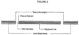
- the general construction of the support and drive limbs 6, may be common although lengths and specific dimensions may change; for example they all use a spring wire core locally rigidised with tubing. Where the wire has no rigidiser it acts as a flexure. This construction provides high stiffness in the axial directions where it is important; i.e. backlash-free in compression and tension, but low stiffness in bending.
- the flexure limb 6 design has various features the design engineer can alter to optimise the stiffness characteristics of the system. They include the wire diameter, the diameter of the rigidised limbs (number of layers of tubing 7), the wire's mechanical properties, the flexure element length and the total limb length.
- MWIR medium wave infra red
- LWIR long wave infra red
- the embodiment described above uses flexures that contain no clearances and are naturally better suited to environments having a large amount of vibration present.
- the flexure construction uses materials that have consistent dimensional and mechanical properties, but that these materials need not be limited to those disclosed above and that any suitable materials may be used.
- lever system described creates a condition of inertial balance and eliminates performance problems associated with linear vibration. It will be appreciated that any mechanism capable of providing such a condition may be substituted for the exact lever system described.
- the image-stabiliser can be used as a primary means of image-stabilisation where the camera body motion is ⁇ +/-2.5% of its FoV.
- the mechanism described could just as easily be applicable to larger percentages if a suitable combination of optical and system parameters permits.
- the image-stabiliser hereinbefore described can be used as a sub-stabiliser within low or high-performance stabilised-platforms.
- the lens gyros described above may be used to control both the lens and platform thus off-setting a significant component cost. It is anticipated this sub-stabiliser approach will support high-performance imaging from a low-performance platform to reduce cost, real estate and mass and other system properties.
- the lens gyros may be used to control other stabilised sensors within a payload.
- the image-stabilizer is compatible with straight or folded optics and may be used in conjunction with Risley prisms to produce an in-line camera/lens with steering and stabilization. Furthermore, the image stabilizer described above may be used to correct small bore sight errors.
- the image-stabilizer may also be used to support the gathering of polarimetric image data using non-homogeneous FPAs.
- the image stabilizer can be used to selectively dither the image to collect real data and eliminate the need for interpolation to compensate for dead pixels within the FPA.
- microscan requires image displacements in controlled half-pixel steps up to 4 times per TV frame and scene-based referencing requires image displacements in controlled whole pixel steps from TV frame to TV frame.
- microscan can provide significant improvements in resolution when viewing static scenes however if the camera is panned (even slowly), the combination of motion and temporal separation of the microscan subfield samples causes the information contained at each pixel to be displayed out of context when the image is reconstructed at the display. The only way to eliminate the problem is to ensure the image remains stationary whilst sampling of all sub-field positions that make up a TV frame. An IS lens approach potentially overcomes the problem.
- modification of the microscan scan pattern from a two-by-two square to a figure-of-eight and re-registration of the displaced TV frames electronically enables image-stabilization, microscan and scene-based referencing functions to operate independently or simultaneously.
Landscapes
- Physics & Mathematics (AREA)
- General Physics & Mathematics (AREA)
- Engineering & Computer Science (AREA)
- Multimedia (AREA)
- Signal Processing (AREA)
- Optics & Photonics (AREA)
- Adjustment Of Camera Lenses (AREA)
- Studio Devices (AREA)
- Accessories Of Cameras (AREA)
Description
- The invention relates to imaging devices. More specifically, but not exclusively it relates to imaging devices including an image-stabilisation module that can either be implemented as an optical relay, or fully integrated into a lens design.
- Known imaging devices including some form of image stabilization module can be found in many commercially available cameras and camcorders. Such devices use gyros to determine camera body angular motion in inertial space, and opto-mechanical mechanisms that move one or more lens elements within an optical path to compensate for image displacement at the focal plane array (FPA).
- When an imaging system is stationary, each pixel on the FPA receives photon flux from a dedicated area within a scene. The charge accumulated at each pixel during a stare time is proportionate to the photon flux received. Diffraction through the optics of the imaging system will result in a small percentage of photon sharing at the pixel boundaries (known as the Airy disc effect). However when angular motion in the imaging system is introduced, the pixels are exposed to features substantially beyond their intended area of coverage. The flux from neighbouring features in the scene is averaged over time across multiple pixels, reducing the Modulation Transfer Function (MTF). From an observer's perspective it becomes increasingly difficult to resolve fine details within the scene and to detect, recognise & identify small, low-contrast targets.
- Angular sightline jitter is a major contributor to system MTF loss for focal plane array (FPA) imaging devices. As focal length increases, overall angle of view and therefore angular-subtense per pixel decreases in object space. Generally, once sightline motion exceeds approximately 25% of the pixel pitch during the detector stare time, it can cause a reduction in MTF that potentially affects overall system performance, reducing the ability to distinguish low contrast features.
- Linear sightline jitter has less impact on devices imaging at long ranges. Each pixel within the FPA subtends an angle into object space, so as the distance to target increases; the area represented by each pixel at the target also increases. For example, if an imager uses a 640 x 512 FPA detector and has a 1º HFoV; each pixel will cover ∼27mm at 1Km and ∼270mm at 10Km. Even with a linear disturbance of 5mm peak to peak, the relative motion of the image compared to a pixel's dimensions would be less than 20% at 1Km and less than 2% at 10Km.
- It should be noted that opto-mechanical image-stabilization and electronic-stabilization are fundamentally different. Opto-mechanical image-stabilization removes sightline jitter before the photon flux arrives at the detector. If a stable image is maintained at the FPA throughout the detector stare time, the charge accumulated at each pixel corresponds accurately to the intended area of coverage within the scene. There is no corruption of signal due to unrelated features moving through a pixel's field of view. Electronic image-stabilization occurs after the photon flux has been detected. It is a post processing function that provides a visual enhancement to an observer by correcting the registration of sequentially displaced TV frames at the display. Electronic-stabilization can compensate for low-frequency scene motion from displayed TV frame to displayed TV frame, however although the presented image may appear stable, the MTF of the raw frame data is likely to be poor.
- Commercial image stabilized camera/lenses are generally intended for handheld use. Although effective at removing low frequency, low acceleration, angular jitter; limitations in the lens construction, configuration and servo bandwidth makes them unsuitable for the harsh dynamic environments associated with more demanding situations.
- Typically, though not exclusively, stabilizing elements within commercial lenses translate across the optical axis to compensate for angular body motion of the camera. The stabilizing element may be mounted on a 2-axis translation stage with each axis driven by a linear actuator, usually in the form of a bespoke voice coil motor (VCM). Significantly, the stabilizing element and armature move in the same direction. For a standard camera system whose lens is focused at infinity, containing no image-stabilization mechanism, linear disturbance is generally undetectable on the image. As described previously, this is because the angular subtense in object space of a single FPA pixel represents a large area at the target; and the area increases with range. Displacements associated with linear vibration are small in comparison.
- In the case of commercially available stabilized lenses, if linear acceleration is applied to the camera/lens body across the optical axis; the disturbing force is transmitted to the stabilizing element by friction within the translation stage slides, and magnetic coupling across the VCM. Opposing the disturbing force is the combined inertia of the stabilizing element and VCM armature, which tends to hold them still in space. If the inertial force exceeds the coupling force from the VCM, the FPA and fixed elements of the lens assembly move with respect to the stabilizing element causing the image to become displaced at the FPA. This gives the appearance of angular jitter and therefore affects imaging performance.
- Commercial image stabilized lenses are generally low bandwidth, not very robust, and susceptible to performance degradation when subjected to linear accelerations across the line of sight. The lens cell slides up and down rails and these sliding interfaces require mechanical clearances that make the assembly prone to wear; particularly if subjected to more harsh environments.
-
US2005/276588 describes an arrangement for driving a correcting lens of an optical camera movement correcting mechanism. - According to the invention there is provided an imaging device according to claim 1.
- The proposed image-stabilised (IS) lens has the capacity to translate the final image across the FPA by approximately +/-2.5% of the FoV (i.e. +/-16 pixels), with full scale deflection anticipated up to 150Hz or greater, rolling off to +/-0.5 pixels at ∼850Hz. It is preferably achieved by translating a single lightweight lens element across the optical axis using a closed-loop servo. Inertial sensors mounted to the lens body determine body motion, and position sensors measure the relationship between the translation cell and lens body to derive sightline direction. The ability to manage a dynamic environment is focal length dependent; with wide FoV systems being inherently more tolerant to body motion than narrow FoV systems due to the increased pixel subtense.
- The inclusion of such a drive-system geometry, that eliminates sensitivity to linear disturbance; allows the image stabilizing mechanism to operate at a higher bandwidth and in doing so, supports a range of performance enhancing system functions. This, therefore, addresses the limitations of commercial lenses and their susceptibility to damage and performance degradation when operating in harsh vibration environments.
- The invention will now be described with reference to the accompanying diagrammatic drawings in which:
-
Figure 1 is a schematic drawing of an imaging device in accordance with one form of the invention showing a lens element mounted in a bezel to form a translational cell, the cell being supported by a series of limbs in a main lens assembly; -
Figure 2 is a schematic drawing showing the support limbs for supporting the lens element within the imaging device ofFigure 1 ; -
Figure 3 is a schematic drawing showing the movement of the limbs ofFigure 2 ; -
Figure 4 is a schematic drawing showing a voice coil motor (VCM) coupled via a coupling mechanism to the cell ofFigure 1 ; and -
Figure 5 is a schematic drawing showing an exploded view of one of the limbs ofFigure 2 . -
Figure 1 shows one form of the image stabilized (IS) device 1. The IS device works by translating a singlelightweight lens element 2 in the X & Y direction across the optical axis 3. Thelens element 2 is bonded into a lightweight aluminium bezel 4 (or other suitable lightweight material), to form atranslation cell 5. - Lens assemblies and/or relay assemblies are typically compound devices comprising a lens body and a number of lens elements that together make up the optical prescription. The
IS lens element 2 is one of the elements in that overall assembly. In the embodiment of the invention described here, the stabilising element is the last element in the optical chain; i.e. the one closest to the FPA, as this is generally the smallest and lightest. However, it will be appreciated that any of the lens elements in the lens assembly may be stabilized in the manner described below. - The
cell 5 is suspended from the body of the main lens assembly on threeflexible support limbs 6 capable of deforming into an 'S'-shape as shown inFigures 2 and3 .Figure 2 's upper view shows a typical straight limb construction, whilst the lower view shows thelimb 6 deflected into two positions (up & down).Figure 3 shows the lens body envelope to the right and the translation cell 5mounted off it to the left, and displaced into two positions. As can be seen from these Figures, the displacement is a parallelogram and the orthogonality of thelens cell 5 is maintained with respect to the optical axis. - The
limbs 6 are fabricated from stainless steel spring wire, stiffened locally with layers of stainless steel tubing 7, welded or bonded together with a high strength adhesive. It will be appreciated that thelimbs 6 and the tubing 7 may be fabricated from any other suitable materials having the required materials properties. The tubing 7 creates rigid elements on either side of the wire flexures and results in a lightweight assembly with very high axial stiffness to retain focus, but low bending stiffness allowing thecell 5 to translate freely. The support limb configuration deforms as a parallelogram and maintains the translation cell's orthogonality to the optical axis when laterally displaced. - X & Y drive is provided by two orthogonally mounted voice coil motors 8 (VCMs) coupled to the
translation cell 5 by drive limbs (60) through alever system 9. TheVCMs 8 provide independent drive in the X & Y directions, the combination of which allows the lens cell to translate anywhere in the X-Y plane. - The construction and characteristics of the drive limbs (60) is similar to the support limbs (6); i.e. having high axial stiffness and low bending stiffness. This provides a rigid coupling in the required drive directions, but compliance in the lateral directions enabling each
VCM 8 to drive thetranslation cell 5 without influencing the other. - The IS lens concept is required to be compatible with a broad range of operating environments. Typical vibration environments impose six degrees-of-freedom, i.e. the vibration spectra contains linear components (displacements in X, Y & Z), and angular components (rotations around X, Y & Z).
- As previously stated, the IS lens is designed to sense and correct angular sightline errors only, and this is achieved by making linear displacements of the
translation cell 5. - If the
cell 5 were to be coupled directly to theVCM 8 armature so that bothcell 5 and armature moved together in the same direction; linear acceleration due to body motion would interact with their combined masses and generate a reaction force equal to the mass x acceleration. TheVCM 8 would not only have to overcome the reaction force, but also apply additional force to compensate for angular sightline motion, making the drive components large and power hungry. - The
lever system 9 creates a condition where thetranslation cell 5 andVCM 8 armature move in opposite directions (seeFigure 4 ). The position of the lever hinge-point is calculated so that the moments of thecell 5 and armature achieve a balanced condition. Under linear acceleration the reaction forces cancel, and all the force generated by theVCM 8 is made available to compensate for angular sightline errors. - It should be noted that the general construction of the support and drive
limbs 6, may be common although lengths and specific dimensions may change; for example they all use a spring wire core locally rigidised with tubing. Where the wire has no rigidiser it acts as a flexure. This construction provides high stiffness in the axial directions where it is important; i.e. backlash-free in compression and tension, but low stiffness in bending. - The
flexure limb 6 design has various features the design engineer can alter to optimise the stiffness characteristics of the system. They include the wire diameter, the diameter of the rigidised limbs (number of layers of tubing 7), the wire's mechanical properties, the flexure element length and the total limb length. - It will be appreciated that the invention may be implemented in medium wave infra red (MWIR) and long wave infra red (LWIR) systems but that the construction techniques can equally be applied to uncooled IR and visual imaging.
- Furthermore, it will be appreciated that the embodiment described above uses flexures that contain no clearances and are naturally better suited to environments having a large amount of vibration present. Moreover, it will be appreciated that the flexure construction uses materials that have consistent dimensional and mechanical properties, but that these materials need not be limited to those disclosed above and that any suitable materials may be used.
- In the embodiment described above, it will be noted that the lever system described creates a condition of inertial balance and eliminates performance problems associated with linear vibration. It will be appreciated that any mechanism capable of providing such a condition may be substituted for the exact lever system described.
- It will be appreciated that the image-stabiliser can be used as a primary means of image-stabilisation where the camera body motion is <+/-2.5% of its FoV. However the mechanism described could just as easily be applicable to larger percentages if a suitable combination of optical and system parameters permits.
- It will be appreciated that high-frequency vibration can be attenuated by the use of anti-vibration mounts at appropriate points in the imaging device.
- Furthermore, it will be appreciated that the image-stabiliser hereinbefore described can be used as a sub-stabiliser within low or high-performance stabilised-platforms. Moreover, the lens gyros described above may be used to control both the lens and platform thus off-setting a significant component cost. It is anticipated this sub-stabiliser approach will support high-performance imaging from a low-performance platform to reduce cost, real estate and mass and other system properties.
- In addition, the lens gyros may be used to control other stabilised sensors within a payload.
- From the description above, it will be appreciated that the image-stabilizer is compatible with straight or folded optics and may be used in conjunction with Risley prisms to produce an in-line camera/lens with steering and stabilization. Furthermore, the image stabilizer described above may be used to correct small bore sight errors.
- The image-stabilizer may also be used to support the gathering of polarimetric image data using non-homogeneous FPAs.
- Furthermore, the image stabilizer can be used to selectively dither the image to collect real data and eliminate the need for interpolation to compensate for dead pixels within the FPA.
- The combination of the construction method and use of high quality components such as fibre-optic gyros and DVRT position sensors allow the operating bandwidth of the system to be extended whilst providing a highly accurate sightline control. This makes the system potentially compatible with various system enhancing functions including but not limited to microscan and scene based referencing. Microscan requires image displacements in controlled half-pixel steps up to 4 times per TV frame and scene-based referencing requires image displacements in controlled whole pixel steps from TV frame to TV frame.
- It is anticipated that combining electronic stabilisation and image registration algorithms with a digitally controlled, opto-mechanical IS lens could provide real benefits to a system. Functionality such as microscan and scene-based referencing could be made available from the same device with the three functions operating either independently or simultaneously. Microscan can provide significant improvements in resolution when viewing static scenes however if the camera is panned (even slowly), the combination of motion and temporal separation of the microscan subfield samples causes the information contained at each pixel to be displayed out of context when the image is reconstructed at the display. The only way to eliminate the problem is to ensure the image remains stationary whilst sampling of all sub-field positions that make up a TV frame. An IS lens approach potentially overcomes the problem.
- In a further embodiment of the invention, modification of the microscan scan pattern from a two-by-two square to a figure-of-eight and re-registration of the displaced TV frames electronically enables image-stabilization, microscan and scene-based referencing functions to operate independently or simultaneously.
Claims (11)
- An imaging device for capturing an image of a scene comprising:a stabilizing module including a translation cell (5) comprising a lens element;flexible support limbs (6) that support the lens element and extend along an optical axis of the lens element; andcharacterised in that the stabilizing module further comprises a coupling mechanism (9, 60) and drive means 8, the coupling mechanism (9,60) interposed between the lens element and the drive means (8) for moving the lens element linearly in a direction opposite to that of the drive means (8) when the lens element is subjected to movement; the coupling mechanism (9,60) comprising flexible drive limbs (60) that support the translation cell (5) and couple the translation cell (5) and the drive means (8), the flexible drive limbs (60) extending in an orthogonal direction to the optical axis of the lens element, the coupling mechanism (9,60) translating movement from the drive means (8) to the lens element via the flexible drive limbs (60).
- An imaging device according to claim 1, wherein the flexible drive limbs (60) are arranged in a system of levers such that said levers create a condition of inertial balance to eliminate an effect of linear vibration.
- An imaging device according to claim 1 or 2 in which a position of a lever hinge-point is calculated such that moments of the lens element and the drive means (8) achieve a balanced condition such that under linear acceleration reaction forces cancel, and all force generated by the drive means (8) is made available to compensate for angular sightline errors in the imaging device.
- An imaging device according to any preceding claim in which the lens element is one of a plurality of lens elements in the imaging device forming a lens assembly, said lens element being suspended from a body of the lens assembly on a series of the flexible support limbs (6) which will deform into an 'S'-shape during operation.
- An imaging device according to claim 4 in which the flexible support limb (6) configuration deforms as a parallelogram thereby maintaining orthogonality of the lens element to an optical axis when laterally displaced.
- An imaging device according to any preceding claim in which the flexible support limbs (6) and flexible drive limbs (60) comprise: spring wire, stiffened locally with layers of tubing, welded or bonded together with a high strength adhesive.
- An imaging device according to claim 6 in which the spring wire and the tubing are formed from stainless steel.
- An imaging device according to any one of claims 2 to 7 in which the levers (9) are formed from stainless steel suitable joined or hinged together.
- An imaging device according to any preceding claim in which the drive means (8) comprises:
two orthogonally mounted voice coil motors (8), the voice coil motors (8) providing independent drive in X and Y directions, a combination of which allows the lens element to translate anywhere in an X-Y plane. - An imaging device according to claim 1, in combination with a camera.
- An imaging device according to claim 2, wherein the system of levers (9) is separated into two sets of series connected levers (9), a first set of levers being connected in series between the drive means (8) and a point on an edge of the lens element, and a second set of levers (9) being connected in series between the drive means (8) and a point on an opposite edge of the lens element.
Applications Claiming Priority (2)
| Application Number | Priority Date | Filing Date | Title |
|---|---|---|---|
| GBGB0918453.2A GB0918453D0 (en) | 2009-10-21 | 2009-10-21 | Imaging device |
| PCT/EP2010/065278 WO2011047990A1 (en) | 2009-10-21 | 2010-10-12 | Imaging device with a stabilizing module |
Publications (2)
| Publication Number | Publication Date |
|---|---|
| EP2491712A1 EP2491712A1 (en) | 2012-08-29 |
| EP2491712B1 true EP2491712B1 (en) | 2020-03-11 |
Family
ID=41426479
Family Applications (1)
| Application Number | Title | Priority Date | Filing Date |
|---|---|---|---|
| EP10763375.2A Active EP2491712B1 (en) | 2009-10-21 | 2010-10-12 | Imaging device with a stabilizing module |
Country Status (7)
| Country | Link |
|---|---|
| US (1) | US9239468B2 (en) |
| EP (1) | EP2491712B1 (en) |
| CA (1) | CA2778488A1 (en) |
| ES (1) | ES2793399T3 (en) |
| GB (1) | GB0918453D0 (en) |
| IL (1) | IL219353A (en) |
| WO (1) | WO2011047990A1 (en) |
Families Citing this family (6)
| Publication number | Priority date | Publication date | Assignee | Title |
|---|---|---|---|---|
| JP5693163B2 (en) * | 2010-11-11 | 2015-04-01 | キヤノン株式会社 | Vibration correction device, lens barrel, and optical apparatus |
| US10491824B2 (en) | 2017-09-26 | 2019-11-26 | Gopro, Inc. | Combined mechanical and electronic image stabilization |
| US11496684B2 (en) | 2017-12-11 | 2022-11-08 | Gopro, Inc. | Combined mechanical and electronic image stabilization |
| US10827123B1 (en) | 2018-01-05 | 2020-11-03 | Gopro, Inc. | Modular image capture systems |
| US10645291B1 (en) | 2018-04-26 | 2020-05-05 | General Atomics Aeronautical Systems, Inc. | Systems and methods to mitigate adverse jitter effects in mobile imaging |
| US11317026B1 (en) | 2020-08-19 | 2022-04-26 | General Atomics Aeronautical Systems, Inc. | Mobile imaging systems and methods utilizing angular velocity in mitigating adverse jitter effects |
Family Cites Families (10)
| Publication number | Priority date | Publication date | Assignee | Title |
|---|---|---|---|---|
| EP0504930B1 (en) | 1991-03-22 | 1998-06-10 | Nikon Corporation | Optical apparatus for correcting image deviation |
| JP4945845B2 (en) | 2000-03-31 | 2012-06-06 | 株式会社ニコン | An optical element holding device, a lens barrel, an exposure apparatus, and a microdevice manufacturing method. |
| EP1277071B1 (en) * | 2000-04-25 | 2008-01-09 | ASML Holding N.V. | Apparatus, system and method for precision positioning and alignment of a lens in an optical system |
| JP4706105B2 (en) * | 2001-01-09 | 2011-06-22 | 株式会社ニコン | Imaging device |
| JP2005352033A (en) | 2004-06-09 | 2005-12-22 | Sony Corp | Lens driving mechanism and imaging apparatus |
| JP4647982B2 (en) | 2004-12-01 | 2011-03-09 | Hoya株式会社 | Imaging device |
| JP4844177B2 (en) | 2006-03-07 | 2011-12-28 | 株式会社ニコン | Blur correction device and camera |
| JP2008197388A (en) | 2007-02-13 | 2008-08-28 | Nikon Corp | Image blur correction device, lens barrel, optical equipment |
| FR2922695A1 (en) * | 2007-10-22 | 2009-04-24 | St Microelectronics Grenoble | MOTOR CONTROL CIRCUIT WITH MOBILE COIL |
| JP5100495B2 (en) * | 2008-05-09 | 2012-12-19 | 株式会社東芝 | Image processing device |
-
2009
- 2009-10-21 GB GBGB0918453.2A patent/GB0918453D0/en not_active Ceased
-
2010
- 2010-10-12 WO PCT/EP2010/065278 patent/WO2011047990A1/en not_active Ceased
- 2010-10-12 CA CA2778488A patent/CA2778488A1/en not_active Abandoned
- 2010-10-12 US US13/503,518 patent/US9239468B2/en active Active
- 2010-10-12 ES ES10763375T patent/ES2793399T3/en active Active
- 2010-10-12 EP EP10763375.2A patent/EP2491712B1/en active Active
-
2012
- 2012-04-22 IL IL219353A patent/IL219353A/en active IP Right Grant
Non-Patent Citations (1)
| Title |
|---|
| None * |
Also Published As
| Publication number | Publication date |
|---|---|
| WO2011047990A1 (en) | 2011-04-28 |
| GB0918453D0 (en) | 2009-12-09 |
| US9239468B2 (en) | 2016-01-19 |
| EP2491712A1 (en) | 2012-08-29 |
| US20120268614A1 (en) | 2012-10-25 |
| IL219353A (en) | 2016-10-31 |
| CA2778488A1 (en) | 2011-04-28 |
| IL219353A0 (en) | 2012-06-28 |
| ES2793399T3 (en) | 2020-11-13 |
Similar Documents
| Publication | Publication Date | Title |
|---|---|---|
| US8212880B2 (en) | Three-axis image stabilization system | |
| US11889203B2 (en) | Camera module | |
| US9239468B2 (en) | Imaging device | |
| EP3540492B1 (en) | Auto focus and optical image stabilization in a compact folded camera | |
| US7804645B2 (en) | Image stabilizer | |
| US7840127B2 (en) | Imaging device with T-shaped shake compensation actuator arrangement | |
| JP5106998B2 (en) | Optical element driving apparatus and imaging apparatus | |
| CN103443702B (en) | Position control device | |
| JP5693163B2 (en) | Vibration correction device, lens barrel, and optical apparatus | |
| US20160212332A1 (en) | Three-axis ois for super-resolution imaging | |
| US9681052B1 (en) | Multi-aperture camera with optical image stabilization function | |
| EP3776065B1 (en) | Method and system for scanning of a focal plane array during earth observation imaging | |
| EP1906233B1 (en) | Imaging device | |
| JP4764075B2 (en) | Image blur correction device and lens barrel provided with the image blur correction device | |
| US20140104482A1 (en) | Imaging device | |
| US20200192186A1 (en) | Spring system and lens anti-shaking device using the same | |
| JP5159090B2 (en) | Optical equipment | |
| JP2008197323A (en) | Optical equipment | |
| CN112312000A (en) | Optical anti-shake realization method | |
| JP6063658B2 (en) | Imaging device | |
| Crawford et al. | THALES long-wave advanced IR QWIP cameras | |
| JP2017161665A (en) | Optical apparatus having image blur correction device | |
| JP2014035477A (en) | Image blur correction device and optical apparatus | |
| Hwang et al. | Design of the Active Optical Compensation Movements for Image Stabilization of Small Satellite | |
| US7149420B1 (en) | Auto-focusing lens with progressive variable focal element |
Legal Events
| Date | Code | Title | Description |
|---|---|---|---|
| PUAI | Public reference made under article 153(3) epc to a published international application that has entered the european phase |
Free format text: ORIGINAL CODE: 0009012 |
|
| 17P | Request for examination filed |
Effective date: 20120419 |
|
| AK | Designated contracting states |
Kind code of ref document: A1 Designated state(s): AL AT BE BG CH CY CZ DE DK EE ES FI FR GB GR HR HU IE IS IT LI LT LU LV MC MK MT NL NO PL PT RO RS SE SI SK SM TR |
|
| DAX | Request for extension of the european patent (deleted) | ||
| RAP1 | Party data changed (applicant data changed or rights of an application transferred) |
Owner name: SELEX ES LTD |
|
| 17Q | First examination report despatched |
Effective date: 20150305 |
|
| RAP1 | Party data changed (applicant data changed or rights of an application transferred) |
Owner name: LEONARDO MW LTD |
|
| STAA | Information on the status of an ep patent application or granted ep patent |
Free format text: STATUS: EXAMINATION IS IN PROGRESS |
|
| GRAP | Despatch of communication of intention to grant a patent |
Free format text: ORIGINAL CODE: EPIDOSNIGR1 |
|
| STAA | Information on the status of an ep patent application or granted ep patent |
Free format text: STATUS: GRANT OF PATENT IS INTENDED |
|
| INTG | Intention to grant announced |
Effective date: 20190729 |
|
| GRAS | Grant fee paid |
Free format text: ORIGINAL CODE: EPIDOSNIGR3 |
|
| GRAJ | Information related to disapproval of communication of intention to grant by the applicant or resumption of examination proceedings by the epo deleted |
Free format text: ORIGINAL CODE: EPIDOSDIGR1 |
|
| GRAL | Information related to payment of fee for publishing/printing deleted |
Free format text: ORIGINAL CODE: EPIDOSDIGR3 |
|
| STAA | Information on the status of an ep patent application or granted ep patent |
Free format text: STATUS: EXAMINATION IS IN PROGRESS |
|
| GRAP | Despatch of communication of intention to grant a patent |
Free format text: ORIGINAL CODE: EPIDOSNIGR1 |
|
| STAA | Information on the status of an ep patent application or granted ep patent |
Free format text: STATUS: GRANT OF PATENT IS INTENDED |
|
| INTC | Intention to grant announced (deleted) | ||
| INTG | Intention to grant announced |
Effective date: 20191030 |
|
| GRAA | (expected) grant |
Free format text: ORIGINAL CODE: 0009210 |
|
| STAA | Information on the status of an ep patent application or granted ep patent |
Free format text: STATUS: THE PATENT HAS BEEN GRANTED |
|
| AK | Designated contracting states |
Kind code of ref document: B1 Designated state(s): AL AT BE BG CH CY CZ DE DK EE ES FI FR GB GR HR HU IE IS IT LI LT LU LV MC MK MT NL NO PL PT RO RS SE SI SK SM TR |
|
| REG | Reference to a national code |
Ref country code: GB Ref legal event code: FG4D |
|
| REG | Reference to a national code |
Ref country code: CH Ref legal event code: EP |
|
| REG | Reference to a national code |
Ref country code: AT Ref legal event code: REF Ref document number: 1244607 Country of ref document: AT Kind code of ref document: T Effective date: 20200315 |
|
| REG | Reference to a national code |
Ref country code: IE Ref legal event code: FG4D |
|
| REG | Reference to a national code |
Ref country code: DE Ref legal event code: R096 Ref document number: 602010063456 Country of ref document: DE |
|
| REG | Reference to a national code |
Ref country code: CH Ref legal event code: NV Representative=s name: INTELLECTUAL PROPERTY SERVICES GMBH, CH |
|
| REG | Reference to a national code |
Ref country code: SE Ref legal event code: TRGR |
|
| REG | Reference to a national code |
Ref country code: NL Ref legal event code: FP |
|
| PG25 | Lapsed in a contracting state [announced via postgrant information from national office to epo] |
Ref country code: NO Free format text: LAPSE BECAUSE OF FAILURE TO SUBMIT A TRANSLATION OF THE DESCRIPTION OR TO PAY THE FEE WITHIN THE PRESCRIBED TIME-LIMIT Effective date: 20200611 Ref country code: FI Free format text: LAPSE BECAUSE OF FAILURE TO SUBMIT A TRANSLATION OF THE DESCRIPTION OR TO PAY THE FEE WITHIN THE PRESCRIBED TIME-LIMIT Effective date: 20200311 Ref country code: RS Free format text: LAPSE BECAUSE OF FAILURE TO SUBMIT A TRANSLATION OF THE DESCRIPTION OR TO PAY THE FEE WITHIN THE PRESCRIBED TIME-LIMIT Effective date: 20200311 |
|
| PG25 | Lapsed in a contracting state [announced via postgrant information from national office to epo] |
Ref country code: BG Free format text: LAPSE BECAUSE OF FAILURE TO SUBMIT A TRANSLATION OF THE DESCRIPTION OR TO PAY THE FEE WITHIN THE PRESCRIBED TIME-LIMIT Effective date: 20200611 Ref country code: HR Free format text: LAPSE BECAUSE OF FAILURE TO SUBMIT A TRANSLATION OF THE DESCRIPTION OR TO PAY THE FEE WITHIN THE PRESCRIBED TIME-LIMIT Effective date: 20200311 Ref country code: GR Free format text: LAPSE BECAUSE OF FAILURE TO SUBMIT A TRANSLATION OF THE DESCRIPTION OR TO PAY THE FEE WITHIN THE PRESCRIBED TIME-LIMIT Effective date: 20200612 Ref country code: LV Free format text: LAPSE BECAUSE OF FAILURE TO SUBMIT A TRANSLATION OF THE DESCRIPTION OR TO PAY THE FEE WITHIN THE PRESCRIBED TIME-LIMIT Effective date: 20200311 |
|
| REG | Reference to a national code |
Ref country code: LT Ref legal event code: MG4D |
|
| PG25 | Lapsed in a contracting state [announced via postgrant information from national office to epo] |
Ref country code: LT Free format text: LAPSE BECAUSE OF FAILURE TO SUBMIT A TRANSLATION OF THE DESCRIPTION OR TO PAY THE FEE WITHIN THE PRESCRIBED TIME-LIMIT Effective date: 20200311 Ref country code: SM Free format text: LAPSE BECAUSE OF FAILURE TO SUBMIT A TRANSLATION OF THE DESCRIPTION OR TO PAY THE FEE WITHIN THE PRESCRIBED TIME-LIMIT Effective date: 20200311 Ref country code: RO Free format text: LAPSE BECAUSE OF FAILURE TO SUBMIT A TRANSLATION OF THE DESCRIPTION OR TO PAY THE FEE WITHIN THE PRESCRIBED TIME-LIMIT Effective date: 20200311 Ref country code: EE Free format text: LAPSE BECAUSE OF FAILURE TO SUBMIT A TRANSLATION OF THE DESCRIPTION OR TO PAY THE FEE WITHIN THE PRESCRIBED TIME-LIMIT Effective date: 20200311 Ref country code: PT Free format text: LAPSE BECAUSE OF FAILURE TO SUBMIT A TRANSLATION OF THE DESCRIPTION OR TO PAY THE FEE WITHIN THE PRESCRIBED TIME-LIMIT Effective date: 20200805 Ref country code: CZ Free format text: LAPSE BECAUSE OF FAILURE TO SUBMIT A TRANSLATION OF THE DESCRIPTION OR TO PAY THE FEE WITHIN THE PRESCRIBED TIME-LIMIT Effective date: 20200311 Ref country code: IS Free format text: LAPSE BECAUSE OF FAILURE TO SUBMIT A TRANSLATION OF THE DESCRIPTION OR TO PAY THE FEE WITHIN THE PRESCRIBED TIME-LIMIT Effective date: 20200711 Ref country code: SK Free format text: LAPSE BECAUSE OF FAILURE TO SUBMIT A TRANSLATION OF THE DESCRIPTION OR TO PAY THE FEE WITHIN THE PRESCRIBED TIME-LIMIT Effective date: 20200311 |
|
| REG | Reference to a national code |
Ref country code: ES Ref legal event code: FG2A Ref document number: 2793399 Country of ref document: ES Kind code of ref document: T3 Effective date: 20201113 |
|
| REG | Reference to a national code |
Ref country code: AT Ref legal event code: MK05 Ref document number: 1244607 Country of ref document: AT Kind code of ref document: T Effective date: 20200311 |
|
| REG | Reference to a national code |
Ref country code: DE Ref legal event code: R097 Ref document number: 602010063456 Country of ref document: DE |
|
| PLBE | No opposition filed within time limit |
Free format text: ORIGINAL CODE: 0009261 |
|
| STAA | Information on the status of an ep patent application or granted ep patent |
Free format text: STATUS: NO OPPOSITION FILED WITHIN TIME LIMIT |
|
| PG25 | Lapsed in a contracting state [announced via postgrant information from national office to epo] |
Ref country code: AT Free format text: LAPSE BECAUSE OF FAILURE TO SUBMIT A TRANSLATION OF THE DESCRIPTION OR TO PAY THE FEE WITHIN THE PRESCRIBED TIME-LIMIT Effective date: 20200311 Ref country code: DK Free format text: LAPSE BECAUSE OF FAILURE TO SUBMIT A TRANSLATION OF THE DESCRIPTION OR TO PAY THE FEE WITHIN THE PRESCRIBED TIME-LIMIT Effective date: 20200311 |
|
| 26N | No opposition filed |
Effective date: 20201214 |
|
| PG25 | Lapsed in a contracting state [announced via postgrant information from national office to epo] |
Ref country code: SI Free format text: LAPSE BECAUSE OF FAILURE TO SUBMIT A TRANSLATION OF THE DESCRIPTION OR TO PAY THE FEE WITHIN THE PRESCRIBED TIME-LIMIT Effective date: 20200311 Ref country code: PL Free format text: LAPSE BECAUSE OF FAILURE TO SUBMIT A TRANSLATION OF THE DESCRIPTION OR TO PAY THE FEE WITHIN THE PRESCRIBED TIME-LIMIT Effective date: 20200311 |
|
| PG25 | Lapsed in a contracting state [announced via postgrant information from national office to epo] |
Ref country code: LU Free format text: LAPSE BECAUSE OF NON-PAYMENT OF DUE FEES Effective date: 20201012 Ref country code: MC Free format text: LAPSE BECAUSE OF FAILURE TO SUBMIT A TRANSLATION OF THE DESCRIPTION OR TO PAY THE FEE WITHIN THE PRESCRIBED TIME-LIMIT Effective date: 20200311 |
|
| REG | Reference to a national code |
Ref country code: BE Ref legal event code: MM Effective date: 20201031 |
|
| REG | Reference to a national code |
Ref country code: DE Ref legal event code: R082 Ref document number: 602010063456 Country of ref document: DE Representative=s name: MANITZ FINSTERWALD PATENT- UND RECHTSANWALTSPA, DE Ref country code: DE Ref legal event code: R081 Ref document number: 602010063456 Country of ref document: DE Owner name: LEONARDO UK LTD, GB Free format text: FORMER OWNER: LEONARDO MW LTD, BASILDON, ESSEX, GB |
|
| PG25 | Lapsed in a contracting state [announced via postgrant information from national office to epo] |
Ref country code: BE Free format text: LAPSE BECAUSE OF NON-PAYMENT OF DUE FEES Effective date: 20201031 |
|
| PG25 | Lapsed in a contracting state [announced via postgrant information from national office to epo] |
Ref country code: IE Free format text: LAPSE BECAUSE OF NON-PAYMENT OF DUE FEES Effective date: 20201012 |
|
| PG25 | Lapsed in a contracting state [announced via postgrant information from national office to epo] |
Ref country code: TR Free format text: LAPSE BECAUSE OF FAILURE TO SUBMIT A TRANSLATION OF THE DESCRIPTION OR TO PAY THE FEE WITHIN THE PRESCRIBED TIME-LIMIT Effective date: 20200311 Ref country code: MT Free format text: LAPSE BECAUSE OF FAILURE TO SUBMIT A TRANSLATION OF THE DESCRIPTION OR TO PAY THE FEE WITHIN THE PRESCRIBED TIME-LIMIT Effective date: 20200311 Ref country code: CY Free format text: LAPSE BECAUSE OF FAILURE TO SUBMIT A TRANSLATION OF THE DESCRIPTION OR TO PAY THE FEE WITHIN THE PRESCRIBED TIME-LIMIT Effective date: 20200311 |
|
| PG25 | Lapsed in a contracting state [announced via postgrant information from national office to epo] |
Ref country code: MK Free format text: LAPSE BECAUSE OF FAILURE TO SUBMIT A TRANSLATION OF THE DESCRIPTION OR TO PAY THE FEE WITHIN THE PRESCRIBED TIME-LIMIT Effective date: 20200311 Ref country code: AL Free format text: LAPSE BECAUSE OF FAILURE TO SUBMIT A TRANSLATION OF THE DESCRIPTION OR TO PAY THE FEE WITHIN THE PRESCRIBED TIME-LIMIT Effective date: 20200311 |
|
| REG | Reference to a national code |
Ref country code: DE Ref legal event code: R079 Ref document number: 602010063456 Country of ref document: DE Free format text: PREVIOUS MAIN CLASS: H04N0005232000 Ipc: H04N0023600000 |
|
| REG | Reference to a national code |
Ref country code: NL Ref legal event code: HC Owner name: LEONARDO UK LTD; GB Free format text: DETAILS ASSIGNMENT: CHANGE OF OWNER(S), CHANGE OF OWNER(S) NAME; FORMER OWNER NAME: LEONARDO MW LTD Effective date: 20230406 |
|
| REG | Reference to a national code |
Ref country code: ES Ref legal event code: PC2A Owner name: LEONARDO UK LTD Effective date: 20240906 |
|
| REG | Reference to a national code |
Ref country code: CH Ref legal event code: U11 Free format text: ST27 STATUS EVENT CODE: U-0-0-U10-U11 (AS PROVIDED BY THE NATIONAL OFFICE) Effective date: 20251101 |
|
| PGFP | Annual fee paid to national office [announced via postgrant information from national office to epo] |
Ref country code: NL Payment date: 20251021 Year of fee payment: 16 |
|
| PGFP | Annual fee paid to national office [announced via postgrant information from national office to epo] |
Ref country code: DE Payment date: 20251021 Year of fee payment: 16 |
|
| PGFP | Annual fee paid to national office [announced via postgrant information from national office to epo] |
Ref country code: GB Payment date: 20251022 Year of fee payment: 16 |
|
| PGFP | Annual fee paid to national office [announced via postgrant information from national office to epo] |
Ref country code: IT Payment date: 20251021 Year of fee payment: 16 |
|
| PGFP | Annual fee paid to national office [announced via postgrant information from national office to epo] |
Ref country code: FR Payment date: 20251030 Year of fee payment: 16 |
|
| PGFP | Annual fee paid to national office [announced via postgrant information from national office to epo] |
Ref country code: SE Payment date: 20251021 Year of fee payment: 16 Ref country code: CH Payment date: 20251101 Year of fee payment: 16 |
|
| PGFP | Annual fee paid to national office [announced via postgrant information from national office to epo] |
Ref country code: ES Payment date: 20251210 Year of fee payment: 16 |