EP2491287B1 - Subsea valve actuator having visual manual position indicator connected to a manual override shaft - Google Patents
Subsea valve actuator having visual manual position indicator connected to a manual override shaft Download PDFInfo
- Publication number
- EP2491287B1 EP2491287B1 EP10824533.3A EP10824533A EP2491287B1 EP 2491287 B1 EP2491287 B1 EP 2491287B1 EP 10824533 A EP10824533 A EP 10824533A EP 2491287 B1 EP2491287 B1 EP 2491287B1
- Authority
- EP
- European Patent Office
- Prior art keywords
- indicator
- actuator
- override shaft
- housing
- carrier
- Prior art date
- Legal status (The legal status is an assumption and is not a legal conclusion. Google has not performed a legal analysis and makes no representation as to the accuracy of the status listed.)
- Not-in-force
Links
- 230000000007 visual effect Effects 0.000 title claims description 19
- 239000012530 fluid Substances 0.000 claims description 28
- 238000007789 sealing Methods 0.000 claims description 14
- 238000006073 displacement reaction Methods 0.000 claims description 6
- 238000006243 chemical reaction Methods 0.000 claims description 5
- 238000004140 cleaning Methods 0.000 claims description 3
- 230000007246 mechanism Effects 0.000 description 6
- 230000004044 response Effects 0.000 description 4
- 239000013535 sea water Substances 0.000 description 4
- 230000001921 mouthing effect Effects 0.000 description 3
- 230000035515 penetration Effects 0.000 description 3
- 230000009467 reduction Effects 0.000 description 3
- 230000004323 axial length Effects 0.000 description 2
- 238000004519 manufacturing process Methods 0.000 description 2
- 238000012986 modification Methods 0.000 description 2
- 238000011179 visual inspection Methods 0.000 description 2
- 208000032843 Hemorrhage Diseases 0.000 description 1
- 230000000712 assembly Effects 0.000 description 1
- 238000000429 assembly Methods 0.000 description 1
- 230000004888 barrier function Effects 0.000 description 1
- 208000034158 bleeding Diseases 0.000 description 1
- 230000000740 bleeding effect Effects 0.000 description 1
- 230000006835 compression Effects 0.000 description 1
- 238000007906 compression Methods 0.000 description 1
- 238000001514 detection method Methods 0.000 description 1
- 238000003912 environmental pollution Methods 0.000 description 1
- 239000004519 grease Substances 0.000 description 1
- 238000009434 installation Methods 0.000 description 1
- 230000004048 modification Effects 0.000 description 1
- 238000012544 monitoring process Methods 0.000 description 1
- 238000005192 partition Methods 0.000 description 1
- XLYOFNOQVPJJNP-UHFFFAOYSA-N water Substances O XLYOFNOQVPJJNP-UHFFFAOYSA-N 0.000 description 1
Images


Classifications
-
- E—FIXED CONSTRUCTIONS
- E21—EARTH OR ROCK DRILLING; MINING
- E21B—EARTH OR ROCK DRILLING; OBTAINING OIL, GAS, WATER, SOLUBLE OR MELTABLE MATERIALS OR A SLURRY OF MINERALS FROM WELLS
- E21B34/00—Valve arrangements for boreholes or wells
- E21B34/02—Valve arrangements for boreholes or wells in well heads
- E21B34/04—Valve arrangements for boreholes or wells in well heads in underwater well heads
-
- F—MECHANICAL ENGINEERING; LIGHTING; HEATING; WEAPONS; BLASTING
- F16—ENGINEERING ELEMENTS AND UNITS; GENERAL MEASURES FOR PRODUCING AND MAINTAINING EFFECTIVE FUNCTIONING OF MACHINES OR INSTALLATIONS; THERMAL INSULATION IN GENERAL
- F16K—VALVES; TAPS; COCKS; ACTUATING-FLOATS; DEVICES FOR VENTING OR AERATING
- F16K37/00—Special means in or on valves or other cut-off apparatus for indicating or recording operation thereof, or for enabling an alarm to be given
- F16K37/0008—Mechanical means
-
- F—MECHANICAL ENGINEERING; LIGHTING; HEATING; WEAPONS; BLASTING
- F16—ENGINEERING ELEMENTS AND UNITS; GENERAL MEASURES FOR PRODUCING AND MAINTAINING EFFECTIVE FUNCTIONING OF MACHINES OR INSTALLATIONS; THERMAL INSULATION IN GENERAL
- F16K—VALVES; TAPS; COCKS; ACTUATING-FLOATS; DEVICES FOR VENTING OR AERATING
- F16K37/00—Special means in or on valves or other cut-off apparatus for indicating or recording operation thereof, or for enabling an alarm to be given
- F16K37/0008—Mechanical means
- F16K37/0016—Mechanical means having a graduated scale
-
- F—MECHANICAL ENGINEERING; LIGHTING; HEATING; WEAPONS; BLASTING
- F16—ENGINEERING ELEMENTS AND UNITS; GENERAL MEASURES FOR PRODUCING AND MAINTAINING EFFECTIVE FUNCTIONING OF MACHINES OR INSTALLATIONS; THERMAL INSULATION IN GENERAL
- F16K—VALVES; TAPS; COCKS; ACTUATING-FLOATS; DEVICES FOR VENTING OR AERATING
- F16K31/00—Actuating devices; Operating means; Releasing devices
- F16K31/02—Actuating devices; Operating means; Releasing devices electric; magnetic
- F16K31/04—Actuating devices; Operating means; Releasing devices electric; magnetic using a motor
-
- F—MECHANICAL ENGINEERING; LIGHTING; HEATING; WEAPONS; BLASTING
- F16—ENGINEERING ELEMENTS AND UNITS; GENERAL MEASURES FOR PRODUCING AND MAINTAINING EFFECTIVE FUNCTIONING OF MACHINES OR INSTALLATIONS; THERMAL INSULATION IN GENERAL
- F16K—VALVES; TAPS; COCKS; ACTUATING-FLOATS; DEVICES FOR VENTING OR AERATING
- F16K31/00—Actuating devices; Operating means; Releasing devices
- F16K31/02—Actuating devices; Operating means; Releasing devices electric; magnetic
- F16K31/04—Actuating devices; Operating means; Releasing devices electric; magnetic using a motor
- F16K31/041—Actuating devices; Operating means; Releasing devices electric; magnetic using a motor for rotating valves
-
- F—MECHANICAL ENGINEERING; LIGHTING; HEATING; WEAPONS; BLASTING
- F16—ENGINEERING ELEMENTS AND UNITS; GENERAL MEASURES FOR PRODUCING AND MAINTAINING EFFECTIVE FUNCTIONING OF MACHINES OR INSTALLATIONS; THERMAL INSULATION IN GENERAL
- F16K—VALVES; TAPS; COCKS; ACTUATING-FLOATS; DEVICES FOR VENTING OR AERATING
- F16K31/00—Actuating devices; Operating means; Releasing devices
- F16K31/44—Mechanical actuating means
-
- F—MECHANICAL ENGINEERING; LIGHTING; HEATING; WEAPONS; BLASTING
- F16—ENGINEERING ELEMENTS AND UNITS; GENERAL MEASURES FOR PRODUCING AND MAINTAINING EFFECTIVE FUNCTIONING OF MACHINES OR INSTALLATIONS; THERMAL INSULATION IN GENERAL
- F16K—VALVES; TAPS; COCKS; ACTUATING-FLOATS; DEVICES FOR VENTING OR AERATING
- F16K37/00—Special means in or on valves or other cut-off apparatus for indicating or recording operation thereof, or for enabling an alarm to be given
- F16K37/0058—Optical means, e.g. light transmission, observation ports
-
- F—MECHANICAL ENGINEERING; LIGHTING; HEATING; WEAPONS; BLASTING
- F16—ENGINEERING ELEMENTS AND UNITS; GENERAL MEASURES FOR PRODUCING AND MAINTAINING EFFECTIVE FUNCTIONING OF MACHINES OR INSTALLATIONS; THERMAL INSULATION IN GENERAL
- F16K—VALVES; TAPS; COCKS; ACTUATING-FLOATS; DEVICES FOR VENTING OR AERATING
- F16K41/00—Spindle sealings
- F16K41/10—Spindle sealings with diaphragm, e.g. shaped as bellows or tube
-
- Y—GENERAL TAGGING OF NEW TECHNOLOGICAL DEVELOPMENTS; GENERAL TAGGING OF CROSS-SECTIONAL TECHNOLOGIES SPANNING OVER SEVERAL SECTIONS OF THE IPC; TECHNICAL SUBJECTS COVERED BY FORMER USPC CROSS-REFERENCE ART COLLECTIONS [XRACs] AND DIGESTS
- Y10—TECHNICAL SUBJECTS COVERED BY FORMER USPC
- Y10T—TECHNICAL SUBJECTS COVERED BY FORMER US CLASSIFICATION
- Y10T137/00—Fluid handling
- Y10T137/8158—With indicator, register, recorder, alarm or inspection means
- Y10T137/8225—Position or extent of motion indicator
-
- Y—GENERAL TAGGING OF NEW TECHNOLOGICAL DEVELOPMENTS; GENERAL TAGGING OF CROSS-SECTIONAL TECHNOLOGIES SPANNING OVER SEVERAL SECTIONS OF THE IPC; TECHNICAL SUBJECTS COVERED BY FORMER USPC CROSS-REFERENCE ART COLLECTIONS [XRACs] AND DIGESTS
- Y10—TECHNICAL SUBJECTS COVERED BY FORMER USPC
- Y10T—TECHNICAL SUBJECTS COVERED BY FORMER US CLASSIFICATION
- Y10T137/00—Fluid handling
- Y10T137/8158—With indicator, register, recorder, alarm or inspection means
- Y10T137/8225—Position or extent of motion indicator
- Y10T137/8275—Indicator element rigidly carried by the movable element whose position is indicated
Definitions
- the present invention relates to a subsea valve actuator comprising an override shaft reaching from inside a fluid filled and pressure compensated actuator housing to the exterior thereof via a bearing and sealing arrangement, wherein a valve position indicator is arranged visible on the exterior of the actuator housing.
- valves for subsea production fluids operate at great depths and corresponding high pressure, low temperature and in conditions of poor visibility. An accurate operation of the valve is crucial and failure may result in loss of production, environmental pollution or safety hazards.
- a subsea valve is typically remotely controlled through valve actuators that are hydraulically or electrically driven for shifting the valve between open, closed and any intermediate positions. The position of the valve may be monitored remotely by means of a position sensor arranged in the actuator and connected to a control centre at a host facility.
- subsea valve actuators are often arranged for manual shifting of the valve by overriding the actuator's normal drive system in response to a visual inspection of the valve position, both of which are accomplished on site by divers or by remotely operated vehicles (ROV).
- ROV remotely operated vehicles
- Subsea valve actuators having manual override and visual position indicator means are previously known.
- US 1386065 A discloses an indicator post for operating a valve and displaying valve position in a buried water main.
- US 4 213 480 A relates to a manual override mechanism for a subsea gate valve.
- EP 0192973 A relates to an actuator for a flow control valve. Further examples of subsea valve actuators are found in EP 0 384 607 A1 , US 2003/0116200 A1 , US 6 487 960 B1 .
- the manual override comprises an override shaft which engages the drive system and which reaches out from a pressure compensated actuator housing with a shaft end that is accessible for manual shifting of the valve.
- An indicator for the valve position is likewise accessible for visual inspection from outside the actuator housing.
- the visual indicator comprises an indicator needle attached to a shaft that reaches into the actuator housing and is connected to the drive system via pinion and reduction gears.
- each penetration of the actuator housing involves a potential risk for ingress of sea water, or the risk of bleeding from the actuator housing which is typically filled with oil or grease.
- the present invention aims at a reduction of the mechanical complexity of the prior subsea valve actuator having a manual override and a valve position indicator which is visually readable from outside an actuator housing.
- Another object of the present invention is to reduce the number of penetrations into the housing of the subsea valve actuator having manual override and a valve position indicator which is visually readable from outside the actuator housing.
- a subsea valve actuator as introduced above, comprising a visual valve position indicator arranged exterior to the actuator housing and pivotally mounted to the override shaft and guided non-rotatably to be forced in axial displacement on the override shaft when the override shaft is rotated, and wherein the mounting of the visual indicator on the override shaft is encased in a fluid filled, pressure compensated indicator mounting enclosure which surrounds the override shaft in a sealing relation outside of the actuator housing, the override shaft having a flow passage by which fluid flow communication is established between the pressure compensated interior of the actuator housing and the interior of the indicator mounting enclosure.
- the indicator mounting enclosure is in fluid flow communication with an external pressure compensator.
- the external pressure compensator may be located in an indicator housing included in a penetrator assembly adapted for introducing the override shaft into the actuator housing.
- the indicator mounting enclosure preferably comprises a first fluid filled chamber which is separated from a second fluid filled chamber through a carrier that is mounted in rotary-to-linear motion conversion engagement with the override shaft.
- the carrier is mounted in threaded engagement with the override shaft.
- the indicator mounting enclosure comprises a first fluid filled chamber which is separated from a second fluid filled chamber through a carrier that is mounted in rotary-to-linear motion conversion engagement with the override shaft, wherein each of said first and second chambers communicates with the interior of the actuator housing via the flow passage formed in the override shaft.
- the flow passage in the override shaft can be realized as an axial bore mouthing in the inner end of the override shaft, connecting with the indicator mounting enclosure via transverse bores mouthing on the periphery of the override shaft within the first and second chambers, respectively.
- Multiple and at least two transverse bores (21) are preferably arranged to mouth within each of the first and second chambers (22; 23).
- the recited measures provide fluid flow into and out from the first and second chambers, the volumes of which will vary in response to the axial displacement of the indicator carrier upon rotation of the override shaft.
- An alternative embodiment foresees a flow passage arranged as an axial groove recessed from the surface of the override shaft.
- one or more flow passages may additionally be formed through the carrier.
- a fluid flow communication between the first and second chambers may in addition or alternatively be established as fluid leakage via a self-cleaning threaded engagement between the carrier and the override shaft.
- first and second chambers are defined by extendable/compressible bellows surrounding the override shaft, each bellow in one end connected to and following the movement of the carrier, and in the opposite end stationary connected to a house portion of an indicator housing.
- the carrier is operatively linked to an indicator needle which is actuated by the carrier to move in linear movement over a scale.
- the carrier is pivotally linked to an indicator needle which is actuated by the carrier to move in pivoting movement over an arcuate scale.
- the indicator needle is extended to reach through a wall of the indicator housing, and the scale is arranged on the exterior of the indicator housing.
- the indicator mounting enclosure may be arranged in an indicator housing forming a penetrator assembly which is connectable to the actuator housing, and by which the override shaft is introduced into the actuator housing.
- An inner end of the indicator housing carries the bearing and sealing arrangement, whereas the outer end of the indicator housing carries a corresponding sealing arrangement and a journal bearing for the override shaft.
- a hydraulically operated subsea valve actuator included in the prior art is shown in fig. 1 , comprising valve shifting components arranged for shifting a valve (not shown) between open and closed positions.
- the valve shifting components are enclosed in an actuator housing 1 which is arranged for connection to a subsea valve.
- An override shaft 2 and a visual valve position indicator 3 are separately introduced into the actuator housing via sealing arrangements 4 and 5, each of which provides a barrier between the ambient sea and the fluid filled and pressure compensated interior of the actuator housing 1.
- the override shaft 2 and visual indicator 3 are each and separately operatively connected to the valve shifting mechanism via pinion and reduction gear assemblies.
- the combined override and visual indicator in a valve actuator according to the present invention is illustrated schematically in fig. 2 .
- An override shaft 6 is introduced in an actuator housing 1 via a bearing and sealing arrangement 7.
- An inner end of the override shaft carries a pinion gear 8 engaging a ring gear comprised in a rotary valve shifting mechanism.
- the opposite or outer end of the override shaft 6 has a shaft end 9 of standard dimension which is exposed and accessible for manual rotation of the override shaft and the valve shifting mechanism, this way overriding the normal drive of the valve shifting mechanism.
- Axially inside of the shaft end 9, the override shaft 6 is rotatably journalled at 10 in a house portion 11 included in an indicator housing, generally identified by reference sign 12.
- the house portion 11 is fastened to the end of an indicator housing wall 13 enclosing an axial length of the override shaft, basically between the bearing and sealing arrangement 7 and the house portion 11.
- the indicator housing 12 represents a penetrator assembly which is connectable to the actuator housing and by which the override shaft 6 is introduced into the pressure compensated interior of the actuator housing.
- a visual position indicator means in the drawings of fig. 2 and 3 generally identified by reference number 14, comprises a carrier 15 which has a through hole threaded internally, and by which the indicator means 14 is mounted in threaded engagement with a threaded portion 16 formed externally on the override shaft 6.
- the carrier 15 is non-rotationally guided through a member 17 which projects to be received for sliding motion in a slot 18 that is formed through the wall 13 of the indicator housing 12.
- the carrier 15 is in this way forced into axial displacement on the override shaft, when the override shaft is rotated. Synchronization between the reading or length of displacement of the carrier 15 and the number of turns of the override shaft, which is required to shift the valve between the fully open and fully closed positions, is determined by the angle of threads and may be adjusted to the subject valve application.
- the mounting of the indicator means 14 on the override shaft 6 is protected from contact with seawater by means of an indicator mounting enclosure 19, essentially encasing the axial length of the override shaft internally of the indicator housing 12.
- the internal pressure in the indicator mounting enclosure 19 is adjusted to the ambient seawater pressure.
- the indicator mounting enclosure 19 is filled with a fluid in flow communication with the fluid-filled and pressure compensated interior of the actuator housing 1. This flow communication is established via a flow passage 20 which is formed as a bore in the override shaft 6.
- the flow passage 20 mouths in the inner end of the override shaft, and connects to the interior of the indicator mounting enclosure 19 via transverse bores 21 mouthing on the surface of the override shaft.
- the bores 21 are arranged to mouth on each side of the carrier 15, the carrier forming a partition member which separates a first chamber 22 from a second chamber 23 of the indicator mounting enclosure 19.
- multiple bores 21 may be arranged axially separated in the override shaft.
- first and second chambers are defined as illustrated through first and second expandable/compressible bellows 24 and 25, respectively.
- the bellows 24 and 25 are in one respective end sealingly connected to the carrier 15, following the same under expansion and compression as the carrier is displaced on the override shaft.
- the bellows are stationary and sealingly connected to the indicator housing 12.
- the override shaft 6 exits from the indicator mounting enclosure 19 via a seal 26 which is seated in a house portion 27 to which the stationary end of bellows 25 is connected.
- the stationary end of bellows 24 may be correspondingly connected to a house portion 28, or connected to the bearing and sealing arrangement 7 via which the drive shaft 6 enters into the actuator housing 1.
- the override shaft 6 thus passes through the indicator mounting enclosure 19 in a sealing relation.
- flow passages 29 are preferably additionally formed through the carrier 15 to provide fluid flow between the first and second chambers defined through the bellows 24 and 25.
- the indicator means 14 comprises an indicator needle moving with the carrier 15.
- an indicator needle 30 is operatively linked to the carrier 15 and reaches to the outside of the indicator housing via a slot in the wall 13 of the indicator housing, so as to be moved by the carrier in a linear motion over a scale 31 which is arranged on the exterior of the indicator housing 12.
- the scale 31 is shown in the drawing as indication marks raised from the outer surface of the indicator housing.
- an alternative indicator needle 32 may be arranged pivotally linked to the carrier 15 so as to be moved by the carrier in a pivoting motion over an arcuate scale 33, as illustrated in fig. 3 .
- reference number 34 refers to a member of a link mechanism which is pivotally engaging the carrier in an axial plane through the override shaft. The link member 34 converts the axial displacement of the carrier 15 into a pivotal motion of the indicator needle 32, while on the other hand a portion 35 of the carrier 15 projects into a guide 36 which prevents the carrier from rotation with the override shaft 6.
- a rotary-to-linear motion conversion engagement is realized as a pin and groove combination wherein a pin on the carrier engages a helical groove formed in the surface of the override shaft, e.g.
- flow communication via the override shaft is omitted and pressure compensation is instead accomplished by means of an external pressure compensator 37 in flow communication at 38 with the interior of the indicator mounting enclosure 19.
- an external pressure compensator may be disposed inside as illustrated, or outside the indicator housing 12 if appropriate.
- an indicator mounting enclosure may be realized as rigid, oppositely arranged cylinders reaching with their open ends towards an inter-disposed carrier which is designed to travel similar to a piston in reciprocating motion in the cylinders, in response to rotation of the override shaft.
- flow communication between the indicator mounting enclosure and the actuator housing may alternatively be accomplished via an axial groove in the surface of the override shaft, e.g.
- a subsea valve actuator is provided which is reliable both in aspects of operation, resulting from a combined override and visual indicator of non-complex mechanical structure, and in aspects of its handling in result of high accessibility for monitoring and manipulation of the valve position by divers or by means of remotely operated vehicles in a subsea environment.
Landscapes
- Engineering & Computer Science (AREA)
- General Engineering & Computer Science (AREA)
- Mechanical Engineering (AREA)
- Mining & Mineral Resources (AREA)
- Life Sciences & Earth Sciences (AREA)
- Geology (AREA)
- Fluid Mechanics (AREA)
- Environmental & Geological Engineering (AREA)
- Physics & Mathematics (AREA)
- General Life Sciences & Earth Sciences (AREA)
- Geochemistry & Mineralogy (AREA)
- Indication Of The Valve Opening Or Closing Status (AREA)
- Geophysics And Detection Of Objects (AREA)
- Measurement Of Velocity Or Position Using Acoustic Or Ultrasonic Waves (AREA)
Description
- The present invention relates to a subsea valve actuator comprising an override shaft reaching from inside a fluid filled and pressure compensated actuator housing to the exterior thereof via a bearing and sealing arrangement, wherein a valve position indicator is arranged visible on the exterior of the actuator housing.
- Basically, valves for subsea production fluids operate at great depths and corresponding high pressure, low temperature and in conditions of poor visibility. An accurate operation of the valve is crucial and failure may result in loss of production, environmental pollution or safety hazards. A subsea valve is typically remotely controlled through valve actuators that are hydraulically or electrically driven for shifting the valve between open, closed and any intermediate positions. The position of the valve may be monitored remotely by means of a position sensor arranged in the actuator and connected to a control centre at a host facility. In a case of failure in the valve positioning system or in the valve position detection function, subsea valve actuators are often arranged for manual shifting of the valve by overriding the actuator's normal drive system in response to a visual inspection of the valve position, both of which are accomplished on site by divers or by remotely operated vehicles (ROV).
- Subsea valve actuators having manual override and visual position indicator means are previously known.
US 1386065 A discloses an indicator post for operating a valve and displaying valve position in a buried water main.US 4 213 480 A relates to a manual override mechanism for a subsea gate valve.EP 0192973 A relates to an actuator for a flow control valve. Further examples of subsea valve actuators are found inEP 0 384 607 A1 ,US 2003/0116200 A1 ,US 6 487 960 B1 . - In a prior art valve actuator, the manual override comprises an override shaft which engages the drive system and which reaches out from a pressure compensated actuator housing with a shaft end that is accessible for manual shifting of the valve. An indicator for the valve position is likewise accessible for visual inspection from outside the actuator housing. The visual indicator comprises an indicator needle attached to a shaft that reaches into the actuator housing and is connected to the drive system via pinion and reduction gears. Besides a mechanically complex structure to ensure synchronization between the movement of the valve and the corresponding reading of the indicator, each penetration of the actuator housing involves a potential risk for ingress of sea water, or the risk of bleeding from the actuator housing which is typically filled with oil or grease.
- The present invention aims at a reduction of the mechanical complexity of the prior subsea valve actuator having a manual override and a valve position indicator which is visually readable from outside an actuator housing.
- Another object of the present invention is to reduce the number of penetrations into the housing of the subsea valve actuator having manual override and a valve position indicator which is visually readable from outside the actuator housing.
- The objects are met in a subsea valve actuator as introduced above, comprising a visual valve position indicator arranged exterior to the actuator housing and pivotally mounted to the override shaft and guided non-rotatably to be forced in axial displacement on the override shaft when the override shaft is rotated, and wherein the mounting of the visual indicator on the override shaft is encased in a fluid filled, pressure compensated indicator mounting enclosure which surrounds the override shaft in a sealing relation outside of the actuator housing, the override shaft having a flow passage by which fluid flow communication is established between the pressure compensated interior of the actuator housing and the interior of the indicator mounting enclosure.
- By the combined arrangement of the override and visual indicator facilities external to the actuator housing there is achieved an arrangement of non-complex mechanical structure. Through the arrangement of pressure compensation there is accomplished a visual indicator which is protected from seawater, and which operates unaffected by pressure and pressure differentials. No additional penetration of the wall of the actuator housing is required besides the unavoidable lead-through of the override shaft.
- In another advantageous realization of the invention, the indicator mounting enclosure is in fluid flow communication with an external pressure compensator. The external pressure compensator may be located in an indicator housing included in a penetrator assembly adapted for introducing the override shaft into the actuator housing.
- The indicator mounting enclosure preferably comprises a first fluid filled chamber which is separated from a second fluid filled chamber through a carrier that is mounted in rotary-to-linear motion conversion engagement with the override shaft.
- Advantageously and preferred, the carrier is mounted in threaded engagement with the override shaft. An alternative embodiment foresees a carrier formed with a pin that engages a helical groove formed on the periphery of the override shaft.
- In a preferred embodiment, the indicator mounting enclosure comprises a first fluid filled chamber which is separated from a second fluid filled chamber through a carrier that is mounted in rotary-to-linear motion conversion engagement with the override shaft, wherein each of said first and second chambers communicates with the interior of the actuator housing via the flow passage formed in the override shaft.
- The flow passage in the override shaft can be realized as an axial bore mouthing in the inner end of the override shaft, connecting with the indicator mounting enclosure via transverse bores mouthing on the periphery of the override shaft within the first and second chambers, respectively. Multiple and at least two transverse bores (21) are preferably arranged to mouth within each of the first and second chambers (22; 23).
- The recited measures provide fluid flow into and out from the first and second chambers, the volumes of which will vary in response to the axial displacement of the indicator carrier upon rotation of the override shaft.
- An alternative embodiment, however less preferred for sealing purposes, foresees a flow passage arranged as an axial groove recessed from the surface of the override shaft.
- Further in order to permit unhindered fluid flow between the first and second chambers, one or more flow passages may additionally be formed through the carrier. A fluid flow communication between the first and second chambers may in addition or alternatively be established as fluid leakage via a self-cleaning threaded engagement between the carrier and the override shaft.
- In the preferred realization of the invention the first and second chambers are defined by extendable/compressible bellows surrounding the override shaft, each bellow in one end connected to and following the movement of the carrier, and in the opposite end stationary connected to a house portion of an indicator housing.
- In one preferred embodiment, the carrier is operatively linked to an indicator needle which is actuated by the carrier to move in linear movement over a scale.
- In another preferred embodiment, the carrier is pivotally linked to an indicator needle which is actuated by the carrier to move in pivoting movement over an arcuate scale.
- In both embodiments, the indicator needle is extended to reach through a wall of the indicator housing, and the scale is arranged on the exterior of the indicator housing.
- The indicator mounting enclosure may be arranged in an indicator housing forming a penetrator assembly which is connectable to the actuator housing, and by which the override shaft is introduced into the actuator housing. An inner end of the indicator housing carries the bearing and sealing arrangement, whereas the outer end of the indicator housing carries a corresponding sealing arrangement and a journal bearing for the override shaft.
- The invention will be further explained below with reference made to the drawings. In the drawings,
-
Fig. 1 is a side view of a prior art valve actuator comprising a manual override and visual valve position indicator; -
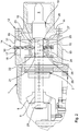
Fig. 2 is a partially sectioned side view of the combined override and visual valve position indicator according to the present invention, schematically illustrating an embodiment of the invention, and -
Fig. 3 is a corresponding view illustrating another embodiment of the combined override and visual valve position indicator. - A hydraulically operated subsea valve actuator included in the prior art is shown in
fig. 1 , comprising valve shifting components arranged for shifting a valve (not shown) between open and closed positions. The valve shifting components are enclosed in anactuator housing 1 which is arranged for connection to a subsea valve. Anoverride shaft 2 and a visualvalve position indicator 3 are separately introduced into the actuator housing viasealing arrangements actuator housing 1. Inside the actuator housing, theoverride shaft 2 andvisual indicator 3 are each and separately operatively connected to the valve shifting mechanism via pinion and reduction gear assemblies. - The combined override and visual indicator in a valve actuator according to the present invention is illustrated schematically in
fig. 2 . Anoverride shaft 6 is introduced in anactuator housing 1 via a bearing andsealing arrangement 7. An inner end of the override shaft carries apinion gear 8 engaging a ring gear comprised in a rotary valve shifting mechanism. The opposite or outer end of theoverride shaft 6 has ashaft end 9 of standard dimension which is exposed and accessible for manual rotation of the override shaft and the valve shifting mechanism, this way overriding the normal drive of the valve shifting mechanism. Axially inside of theshaft end 9, theoverride shaft 6 is rotatably journalled at 10 in ahouse portion 11 included in an indicator housing, generally identified byreference sign 12. Thehouse portion 11 is fastened to the end of anindicator housing wall 13 enclosing an axial length of the override shaft, basically between the bearing andsealing arrangement 7 and thehouse portion 11. Theindicator housing 12 represents a penetrator assembly which is connectable to the actuator housing and by which theoverride shaft 6 is introduced into the pressure compensated interior of the actuator housing. - A visual position indicator means, in the drawings of
fig. 2 and3 generally identified byreference number 14, comprises acarrier 15 which has a through hole threaded internally, and by which the indicator means 14 is mounted in threaded engagement with a threadedportion 16 formed externally on theoverride shaft 6. Thecarrier 15 is non-rotationally guided through amember 17 which projects to be received for sliding motion in aslot 18 that is formed through thewall 13 of theindicator housing 12. Thecarrier 15 is in this way forced into axial displacement on the override shaft, when the override shaft is rotated. Synchronization between the reading or length of displacement of thecarrier 15 and the number of turns of the override shaft, which is required to shift the valve between the fully open and fully closed positions, is determined by the angle of threads and may be adjusted to the subject valve application. - The mounting of the indicator means 14 on the
override shaft 6 is protected from contact with seawater by means of anindicator mounting enclosure 19, essentially encasing the axial length of the override shaft internally of theindicator housing 12. The internal pressure in theindicator mounting enclosure 19 is adjusted to the ambient seawater pressure. In the illustrated example, theindicator mounting enclosure 19 is filled with a fluid in flow communication with the fluid-filled and pressure compensated interior of theactuator housing 1. This flow communication is established via aflow passage 20 which is formed as a bore in theoverride shaft 6. Theflow passage 20 mouths in the inner end of the override shaft, and connects to the interior of theindicator mounting enclosure 19 via transverse bores 21 mouthing on the surface of the override shaft. Notably, thebores 21 are arranged to mouth on each side of thecarrier 15, the carrier forming a partition member which separates afirst chamber 22 from asecond chamber 23 of theindicator mounting enclosure 19. In order to establish flow communication with the interior of the actuator housing, regardless of position of thecarrier 15 on theoverride shaft 6,multiple bores 21 may be arranged axially separated in the override shaft. - Preferably, the first and second chambers are defined as illustrated through first and second expandable/
compressible bellows carrier 15, following the same under expansion and compression as the carrier is displaced on the override shaft. In the opposite ends, the bellows are stationary and sealingly connected to theindicator housing 12. Theoverride shaft 6 exits from theindicator mounting enclosure 19 via aseal 26 which is seated in ahouse portion 27 to which the stationary end ofbellows 25 is connected. The stationary end ofbellows 24 may be correspondingly connected to ahouse portion 28, or connected to the bearing and sealingarrangement 7 via which thedrive shaft 6 enters into theactuator housing 1. Theoverride shaft 6 thus passes through theindicator mounting enclosure 19 in a sealing relation. - The volumes of the bellows thus shift in response to the rotation of the override shaft. In order to further ensure unrestricted fluid flow into and out from the chambers of changing volumes, flow
passages 29 are preferably additionally formed through thecarrier 15 to provide fluid flow between the first and second chambers defined through thebellows - The indicator means 14 comprises an indicator needle moving with the
carrier 15. In a preferred embodiment, illustrated infig. 2 , anindicator needle 30 is operatively linked to thecarrier 15 and reaches to the outside of the indicator housing via a slot in thewall 13 of the indicator housing, so as to be moved by the carrier in a linear motion over ascale 31 which is arranged on the exterior of theindicator housing 12. For purpose of illustration, thescale 31 is shown in the drawing as indication marks raised from the outer surface of the indicator housing. - Modifications to the above embodiment are possible. Instead of an
indicator needle 30 moving linearly over ascale 31, analternative indicator needle 32 may be arranged pivotally linked to thecarrier 15 so as to be moved by the carrier in a pivoting motion over anarcuate scale 33, as illustrated infig. 3 . In the drawing,reference number 34 refers to a member of a link mechanism which is pivotally engaging the carrier in an axial plane through the override shaft. Thelink member 34 converts the axial displacement of thecarrier 15 into a pivotal motion of theindicator needle 32, while on the other hand aportion 35 of thecarrier 15 projects into aguide 36 which prevents the carrier from rotation with theoverride shaft 6. - In alternative to a threaded engagement between the
carrier 15 and theoverride shaft 6 as disclosed, an embodiment is foreseen wherein a rotary-to-linear motion conversion engagement is realized as a pin and groove combination wherein a pin on the carrier engages a helical groove formed in the surface of the override shaft, e.g. - In another alternative embodiment, see
fig. 3 , flow communication via the override shaft is omitted and pressure compensation is instead accomplished by means of anexternal pressure compensator 37 in flow communication at 38 with the interior of theindicator mounting enclosure 19. In this embodiment, an external pressure compensator may be disposed inside as illustrated, or outside theindicator housing 12 if appropriate. - It is further conceivable to establish flow communication between the first and second chambers of the
indicator mounting enclosure 19 as a leak flow via self-cleaning threads in the mounting of the indicator means 14 on the override shaft. - In alternative to the
bellows
Claims (15)
- A subsea valve actuator, comprising an override shaft (6) that reaches from inside a fluid filled and pressure compensated actuator housing (1) to the exterior thereof via a bearing and sealing arrangement (7), wherein a visual valve position indicator (14) is arranged exterior to the actuator housing, the visual indicator (14) pivotally mounted to the override shaft and guided non-rotatably to be forced in axial displacement on the override shaft when the override shaft is rotated, and wherein the mounting of the visual indicator (14) on the override shaft (6) is encased in a fluid filled, pressure compensated indicator mounting enclosure (19) surrounding the override shaft (6) in sealing (26) relation outside of the actuator housing (1), characterized in that, the override shaft (6) having a flow passage (20) by which fluid flow communication is established between the pressure compensated interior of the actuator housing (1) and the interior of the indicator mounting enclosure (19).
- The subsea actuator of claim 1, characterized in that the indicator mounting enclosure (19) is in fluid flow communication with an external pressure compensator (37).
- The subsea actuator of claim 2, characterized in that the external pressure compensator (37) is located in an indicator housing (12) included in a penetrator assembly adapted for introducing the override shaft (6) into the actuator housing (1).
- The subsea actuator of any of claims 1 to 3, characterized in that the indicator mounting enclosure (19) comprises a first fluid filled chamber (22) which is separated from a second fluid filled chamber (23) through a carrier (15) which is mounted in rotary- to- linear motion conversion engagement with the override shaft (6).
- The subsea actuator of claim 1, characterized in that the indicator mounting enclosure (19) comprises a first fluid filled chamber (22) which is separated from a second fluid filled chamber (23) through a carrier (15) which is mounted in rotary-to-linear motion conversion engagement with the override shaft (6), wherein each of said first and second chambers communicates with the interior of the actuator housing (1) via the flow passage (20) in the override shaft.
- The subsea actuator of claim 5, characterized in that the flow passage (20) in the override shaft (6) is an axial bore mounting in the inner end of the override shaft, connecting with the indicator mounting enclosure (19) via transverse bores (21) mounting on the periphery of the override shaft within the first and second chambers (22; 23), respectively.
- The subsea actuator of claim 6, characterized in that multiple and at least two transverse bores (21) are arranged to mount within each of the first and second chambers (22; 23), respectively.
- The subsea actuator of any of claims 4 to 7, characterized in that at least one flow passage (29) is formed through the carrier (15), permitting fluid flow between the first and second chambers (22; 23).
- The subsea actuator of any of claims 4 to 8, characterized in that the first and second chambers (22; 23) are defined by extendable/ compressible bellows (24; 25) surrounding the override shaft, each bellow in one end connected to the carrier (15) and in the opposite end stationary connected to a house portion of an indicator housing (12).
- The subsea actuator of any of claims 4 to 9, characterized in that the carrier (15) is mounted in threaded engagement with the override shaft (6).
- The subsea actuator of claim 10, characterized in that fluid leakage between the first and second chambers (22; 23) of the indicator mounting enclosure (19) is permitted via a self-cleaning threaded engagement between the carrier (15) and the override shaft (6).
- The subsea actuator of any of claims 4 to 11, characterized in that the carrier (15) is operatively linked to an indicator needle (30) which is actuated by the carrier to move in linear movement over a scale (31).
- The subsea actuator of any of claims 4 to 11, characterized in that the carrier (15) is pivotally linked to an indicator needle (32) which is actuated by the carrier to move in pivoting movement over an arcuate scale (33).
- The subsea actuator of claim 12 or 13, characterized in that the indicator needle (30; 32) reaches through a wall (13) of the indicator housing (12), and in that the scale (31; 33) is arranged on the exterior of the indicator housing.
- The subsea actuator of any previous claim, characterized in that the indicator mounting enclosure (19) is arranged in an indicator housing (12) forming a penetrator assembly which is connectable to the actuator housing (1) and by which the override shaft (6) is introduced into the actuator housing, the indicator housing (12) in an inner end thereof carrying the bearing and sealing arrangement (7) and in an outer end carrying a corresponding sealing arrangement (26) and a journal bearing (10) for the override shaft (6).
Priority Applications (1)
| Application Number | Priority Date | Filing Date | Title |
|---|---|---|---|
| PL10824533T PL2491287T3 (en) | 2009-10-21 | 2010-10-19 | Subsea valve actuator having visual manual position indicator connected to a manual override shaft |
Applications Claiming Priority (2)
| Application Number | Priority Date | Filing Date | Title |
|---|---|---|---|
| NO20093189A NO338078B1 (en) | 2009-10-21 | 2009-10-21 | Submarine valve actuator with visual valve position indicator connected to a manual override shaft |
| PCT/IB2010/002670 WO2011048469A1 (en) | 2009-10-21 | 2010-10-19 | Subsea valve actuator having visual manual position indicator connected to a manual override shaft |
Publications (3)
| Publication Number | Publication Date |
|---|---|
| EP2491287A1 EP2491287A1 (en) | 2012-08-29 |
| EP2491287A4 EP2491287A4 (en) | 2017-02-15 |
| EP2491287B1 true EP2491287B1 (en) | 2018-06-27 |
Family
ID=43899868
Family Applications (1)
| Application Number | Title | Priority Date | Filing Date |
|---|---|---|---|
| EP10824533.3A Not-in-force EP2491287B1 (en) | 2009-10-21 | 2010-10-19 | Subsea valve actuator having visual manual position indicator connected to a manual override shaft |
Country Status (9)
| Country | Link |
|---|---|
| US (1) | US9103459B2 (en) |
| EP (1) | EP2491287B1 (en) |
| CN (1) | CN102725573B (en) |
| AU (1) | AU2010309493B2 (en) |
| BR (1) | BR112012009210B1 (en) |
| MY (1) | MY156116A (en) |
| NO (1) | NO338078B1 (en) |
| PL (1) | PL2491287T3 (en) |
| WO (1) | WO2011048469A1 (en) |
Families Citing this family (32)
| Publication number | Priority date | Publication date | Assignee | Title |
|---|---|---|---|---|
| GB2487542B (en) * | 2011-01-25 | 2013-06-12 | Vector Int Ltd | ROV drive bucket plug |
| US8550167B2 (en) * | 2011-03-21 | 2013-10-08 | Vetco Gray Inc. | Remote operated vehicle interface with overtorque protection |
| NO334269B1 (en) | 2012-05-29 | 2014-01-27 | Fmc Technologies Ltd | Determination of position for hydraulic submarine actuator |
| US8978699B2 (en) | 2012-09-07 | 2015-03-17 | Cameron International Corporation | Blowout preventer status assembly |
| ITTO20130250A1 (en) * | 2013-03-27 | 2014-09-28 | Mtm Hydro S R L | PERFECTED BYPASS VALVE FOR A WASHING SYSTEM |
| US9500289B2 (en) | 2014-05-20 | 2016-11-22 | Dresser, Inc. | Device to provide failsafe mechanism on a valve actuator assembly |
| WO2015185325A1 (en) * | 2014-06-04 | 2015-12-10 | Siemens Aktiengesellschaft | Pressure compensator and electrical connection device |
| CN105298442B (en) * | 2015-11-02 | 2017-10-03 | 江苏科技大学 | A kind of movable and rotary type linearly covers instrument |
| CN105298444B (en) * | 2015-11-02 | 2017-10-03 | 江苏科技大学 | A kind of rotary linear covering instrument |
| US20170130577A1 (en) * | 2015-11-11 | 2017-05-11 | Ge Oil & Gas Pressure Control Lp | True Position Indicator |
| US9822603B2 (en) * | 2015-12-30 | 2017-11-21 | Cameron International Corporation | Subsea equipment visual indicator |
| NO342327B1 (en) * | 2016-01-28 | 2018-05-07 | Vetco Gray Scandinavia As | Subsea arrangement |
| US10371284B2 (en) * | 2016-02-16 | 2019-08-06 | Baker Hughes, A Ge Company, Llc | Local position indicator for subsea isolation valve having no external position indication |
| US9810343B2 (en) | 2016-03-10 | 2017-11-07 | Baker Hughes, A Ge Company, Llc | Pressure compensated flow tube for deep set tubular isolation valve |
| GB2550359A (en) * | 2016-05-16 | 2017-11-22 | Ge Oil & Gas Uk Ltd | Actuator Apparatus, system and method |
| CH714023A1 (en) * | 2017-07-27 | 2019-01-31 | Liebherr Machines Bulle Sa | Hydraulic device, in particular hydraulic valve or hydraulic regulator. |
| CN107327435A (en) * | 2017-08-21 | 2017-11-07 | 泸州精通流体液压机械有限公司 | A kind of method commutated by electric control system controls hydraulic valve |
| US10745994B2 (en) * | 2018-04-24 | 2020-08-18 | Ge Oil & Gas Pressure Control Lp | System and method for preventing inadvertent valve closures |
| CN109211367A (en) * | 2018-09-28 | 2019-01-15 | 镇江市计量检定测试中心 | A kind of pVTt method gas flow standard device |
| CN109211368A (en) * | 2018-09-28 | 2019-01-15 | 镇江市计量检定测试中心 | A kind of pVTt method gas flow standard system with control equipment |
| CN109211364A (en) * | 2018-09-28 | 2019-01-15 | 镇江市计量检定测试中心 | A kind of Multipurpose gas flow standard system with control equipment |
| CN109211371A (en) * | 2018-09-28 | 2019-01-15 | 镇江市计量检定测试中心 | A kind of pVTt method gas flow standard device based on air supply system |
| CN109211366A (en) * | 2018-09-28 | 2019-01-15 | 镇江市计量检定测试中心 | A kind of Multipurpose gas flow standard device based on air supply system |
| CN109211370A (en) * | 2018-09-28 | 2019-01-15 | 镇江市计量检定测试中心 | A kind of multipurpose pVTt method gas flow standard detection system |
| CN109211369A (en) * | 2018-09-28 | 2019-01-15 | 镇江市计量检定测试中心 | A kind of pVTt method gas flow standard detection system |
| CN109211365A (en) * | 2018-09-28 | 2019-01-15 | 镇江市计量检定测试中心 | A kind of multipurpose pVTt method gas flow standard device |
| CN109681684B (en) * | 2019-01-21 | 2020-08-04 | 中国船舶科学研究中心(中国船舶重工集团公司第七0二研究所) | An emergency load dump safety valve suitable for submersible piping system |
| IT201900002451A1 (en) * | 2019-02-20 | 2020-08-20 | Actuator Fluid Control S R L In Breve Afc S R L | Fluidic actuator for a valve or similar element |
| US20240088744A1 (en) * | 2021-01-25 | 2024-03-14 | Linak A/S | A linear actuator comprising a visual status indicator |
| USD1001843S1 (en) * | 2021-03-29 | 2023-10-17 | Robert Bosch Gmbh | Subsea valve actuator |
| EP4562273A1 (en) | 2022-07-26 | 2025-06-04 | TechnipFMC Norge AS | Subsea actuation sub-system |
| NO20220830A1 (en) * | 2022-07-26 | 2024-01-29 | Fmc Kongsberg Subsea As | Subsea actuation system with retrievable position indicator |
Family Cites Families (17)
| Publication number | Priority date | Publication date | Assignee | Title |
|---|---|---|---|---|
| US1386065A (en) * | 1919-08-29 | 1921-08-02 | Herbert M Lofton | Indicator-post |
| GB939353A (en) * | 1961-02-28 | 1963-10-16 | Rotork Eng Co Ltd | Improvements in or relating to valve actuators |
| US3198034A (en) * | 1961-11-17 | 1965-08-03 | Stamicarbon | Valve actuator |
| DE1283464B (en) * | 1964-12-24 | 1968-11-21 | Draegerwerk Ag | Rotary slide valve for pressure change mattresses |
| US3331583A (en) * | 1966-06-23 | 1967-07-18 | Elizabeth N Willis | Balanced shut-off valve |
| US4213480A (en) | 1978-12-26 | 1980-07-22 | Acf Industries, Incorporated | Manual override for hydraulic gate valve actuators |
| US4406303A (en) * | 1981-08-04 | 1983-09-27 | Acf Industries, Incorporated | Gate valve with position indicator |
| US4622994A (en) * | 1984-08-15 | 1986-11-18 | Rosaen Nils O | Fluid handling device |
| DE3503598C1 (en) | 1985-02-02 | 1986-01-23 | Klein, Schanzlin & Becker Ag, 6710 Frankenthal | Shut-off valve to be operated by a servomotor |
| US4643390A (en) * | 1985-02-26 | 1987-02-17 | Gray Tool Company | Fail-safe valve actuator |
| ATE124117T1 (en) | 1989-02-22 | 1995-07-15 | Cooper Ind Inc | ACTUATED GATE VALVE WITH SUPERIOR MANUAL OPERATION. |
| GB9113963D0 (en) * | 1991-06-28 | 1991-08-14 | Alpha Thames Eng | Valve actuator |
| US5890450A (en) * | 1997-07-01 | 1999-04-06 | Fmc Corporation | Linear stroke valve position indicator |
| US6609533B2 (en) * | 2001-03-08 | 2003-08-26 | World Wide Oilfield Machine, Inc. | Valve actuator and method |
| US6487960B1 (en) | 2001-08-09 | 2002-12-03 | Hp&T Products, Inc. | Hydraulic failsafe valve actuator |
| ITMI20040022A1 (en) * | 2004-01-13 | 2004-04-13 | Dresser Italia S R L | ACTUATOR FOR THE OPERATION OF SUBMARINE DEVICES |
| JP4506437B2 (en) * | 2004-04-30 | 2010-07-21 | Smc株式会社 | 2-port valve for vacuum pressure |
-
2009
- 2009-10-21 NO NO20093189A patent/NO338078B1/en unknown
-
2010
- 2010-10-19 PL PL10824533T patent/PL2491287T3/en unknown
- 2010-10-19 WO PCT/IB2010/002670 patent/WO2011048469A1/en not_active Ceased
- 2010-10-19 EP EP10824533.3A patent/EP2491287B1/en not_active Not-in-force
- 2010-10-19 US US13/502,899 patent/US9103459B2/en active Active
- 2010-10-19 BR BR112012009210-3A patent/BR112012009210B1/en not_active IP Right Cessation
- 2010-10-19 MY MYPI2012001218A patent/MY156116A/en unknown
- 2010-10-19 AU AU2010309493A patent/AU2010309493B2/en not_active Ceased
- 2010-10-19 CN CN201080048167.5A patent/CN102725573B/en not_active Expired - Fee Related
Non-Patent Citations (1)
| Title |
|---|
| None * |
Also Published As
| Publication number | Publication date |
|---|---|
| US9103459B2 (en) | 2015-08-11 |
| CN102725573A (en) | 2012-10-10 |
| MY156116A (en) | 2016-01-15 |
| BR112012009210A2 (en) | 2017-06-20 |
| EP2491287A1 (en) | 2012-08-29 |
| US20120234410A1 (en) | 2012-09-20 |
| CN102725573B (en) | 2016-06-29 |
| AU2010309493B2 (en) | 2014-10-30 |
| WO2011048469A1 (en) | 2011-04-28 |
| PL2491287T3 (en) | 2019-03-29 |
| NO338078B1 (en) | 2016-07-25 |
| NO20093189A1 (en) | 2011-04-26 |
| BR112012009210B1 (en) | 2020-07-14 |
| AU2010309493A1 (en) | 2012-05-17 |
| EP2491287A4 (en) | 2017-02-15 |
| BR112012009210A8 (en) | 2020-05-19 |
Similar Documents
| Publication | Publication Date | Title |
|---|---|---|
| US9103459B2 (en) | Subsea valve actuator having visual manual position indicator connected to a manual override shaft | |
| US4635901A (en) | Position indicator for valves | |
| AU2016318342B2 (en) | Linear actuator with rotary positional output | |
| AU2007243953B2 (en) | Fluid powered dual-piston actuator with efficient fluid porting and method of implementation | |
| MX2011013155A (en) | Valve. | |
| US20210190099A1 (en) | Electrohydraulic System for Use under Water, Comprising an Electrohydraulic Actuator | |
| AU2011238990B2 (en) | Device for electromechanical actuator | |
| CN105333194A (en) | Rotating operation driving device of underwater gate valve | |
| US8919374B2 (en) | Hydraulic control valve with two valve slides | |
| CN102979480A (en) | Ball valve assembly | |
| CN117072718A (en) | Hydraulic pilot-controlled two-position four-way water medium reversing ball valve | |
| CN100441918C (en) | A shift oil cylinder of an electronically controlled mechanical automatic transmission for automobiles | |
| NO135077B (en) | ||
| GB2635331A (en) | Subsea actuator and associated methods |
Legal Events
| Date | Code | Title | Description |
|---|---|---|---|
| PUAI | Public reference made under article 153(3) epc to a published international application that has entered the european phase |
Free format text: ORIGINAL CODE: 0009012 |
|
| 17P | Request for examination filed |
Effective date: 20120316 |
|
| AK | Designated contracting states |
Kind code of ref document: A1 Designated state(s): AL AT BE BG CH CY CZ DE DK EE ES FI FR GB GR HR HU IE IS IT LI LT LU LV MC MK MT NL NO PL PT RO RS SE SI SK SM TR |
|
| DAX | Request for extension of the european patent (deleted) | ||
| RA4 | Supplementary search report drawn up and despatched (corrected) |
Effective date: 20170112 |
|
| RIC1 | Information provided on ipc code assigned before grant |
Ipc: E21B 21/10 20060101ALI20170106BHEP Ipc: F16K 37/00 20060101AFI20170106BHEP Ipc: F16K 31/04 20060101ALI20170106BHEP |
|
| GRAP | Despatch of communication of intention to grant a patent |
Free format text: ORIGINAL CODE: EPIDOSNIGR1 |
|
| INTG | Intention to grant announced |
Effective date: 20180301 |
|
| GRAS | Grant fee paid |
Free format text: ORIGINAL CODE: EPIDOSNIGR3 |
|
| GRAA | (expected) grant |
Free format text: ORIGINAL CODE: 0009210 |
|
| AK | Designated contracting states |
Kind code of ref document: B1 Designated state(s): AL AT BE BG CH CY CZ DE DK EE ES FI FR GB GR HR HU IE IS IT LI LT LU LV MC MK MT NL NO PL PT RO RS SE SI SK SM TR |
|
| REG | Reference to a national code |
Ref country code: GB Ref legal event code: FG4D |
|
| REG | Reference to a national code |
Ref country code: AT Ref legal event code: REF Ref document number: 1012644 Country of ref document: AT Kind code of ref document: T Effective date: 20180715 |
|
| REG | Reference to a national code |
Ref country code: IE Ref legal event code: FG4D |
|
| REG | Reference to a national code |
Ref country code: DE Ref legal event code: R096 Ref document number: 602010051564 Country of ref document: DE |
|
| REG | Reference to a national code |
Ref country code: FR Ref legal event code: PLFP Year of fee payment: 9 |
|
| PG25 | Lapsed in a contracting state [announced via postgrant information from national office to epo] |
Ref country code: NO Free format text: LAPSE BECAUSE OF FAILURE TO SUBMIT A TRANSLATION OF THE DESCRIPTION OR TO PAY THE FEE WITHIN THE PRESCRIBED TIME-LIMIT Effective date: 20180927 Ref country code: SE Free format text: LAPSE BECAUSE OF FAILURE TO SUBMIT A TRANSLATION OF THE DESCRIPTION OR TO PAY THE FEE WITHIN THE PRESCRIBED TIME-LIMIT Effective date: 20180627 Ref country code: FI Free format text: LAPSE BECAUSE OF FAILURE TO SUBMIT A TRANSLATION OF THE DESCRIPTION OR TO PAY THE FEE WITHIN THE PRESCRIBED TIME-LIMIT Effective date: 20180627 Ref country code: BG Free format text: LAPSE BECAUSE OF FAILURE TO SUBMIT A TRANSLATION OF THE DESCRIPTION OR TO PAY THE FEE WITHIN THE PRESCRIBED TIME-LIMIT Effective date: 20180927 Ref country code: LT Free format text: LAPSE BECAUSE OF FAILURE TO SUBMIT A TRANSLATION OF THE DESCRIPTION OR TO PAY THE FEE WITHIN THE PRESCRIBED TIME-LIMIT Effective date: 20180627 |
|
| REG | Reference to a national code |
Ref country code: NL Ref legal event code: MP Effective date: 20180627 |
|
| REG | Reference to a national code |
Ref country code: LT Ref legal event code: MG4D |
|
| PG25 | Lapsed in a contracting state [announced via postgrant information from national office to epo] |
Ref country code: LV Free format text: LAPSE BECAUSE OF FAILURE TO SUBMIT A TRANSLATION OF THE DESCRIPTION OR TO PAY THE FEE WITHIN THE PRESCRIBED TIME-LIMIT Effective date: 20180627 Ref country code: RS Free format text: LAPSE BECAUSE OF FAILURE TO SUBMIT A TRANSLATION OF THE DESCRIPTION OR TO PAY THE FEE WITHIN THE PRESCRIBED TIME-LIMIT Effective date: 20180627 Ref country code: HR Free format text: LAPSE BECAUSE OF FAILURE TO SUBMIT A TRANSLATION OF THE DESCRIPTION OR TO PAY THE FEE WITHIN THE PRESCRIBED TIME-LIMIT Effective date: 20180627 Ref country code: GR Free format text: LAPSE BECAUSE OF FAILURE TO SUBMIT A TRANSLATION OF THE DESCRIPTION OR TO PAY THE FEE WITHIN THE PRESCRIBED TIME-LIMIT Effective date: 20180928 |
|
| REG | Reference to a national code |
Ref country code: AT Ref legal event code: MK05 Ref document number: 1012644 Country of ref document: AT Kind code of ref document: T Effective date: 20180627 |
|
| PG25 | Lapsed in a contracting state [announced via postgrant information from national office to epo] |
Ref country code: NL Free format text: LAPSE BECAUSE OF FAILURE TO SUBMIT A TRANSLATION OF THE DESCRIPTION OR TO PAY THE FEE WITHIN THE PRESCRIBED TIME-LIMIT Effective date: 20180627 |
|
| PG25 | Lapsed in a contracting state [announced via postgrant information from national office to epo] |
Ref country code: CZ Free format text: LAPSE BECAUSE OF FAILURE TO SUBMIT A TRANSLATION OF THE DESCRIPTION OR TO PAY THE FEE WITHIN THE PRESCRIBED TIME-LIMIT Effective date: 20180627 Ref country code: RO Free format text: LAPSE BECAUSE OF FAILURE TO SUBMIT A TRANSLATION OF THE DESCRIPTION OR TO PAY THE FEE WITHIN THE PRESCRIBED TIME-LIMIT Effective date: 20180627 Ref country code: IS Free format text: LAPSE BECAUSE OF FAILURE TO SUBMIT A TRANSLATION OF THE DESCRIPTION OR TO PAY THE FEE WITHIN THE PRESCRIBED TIME-LIMIT Effective date: 20181027 Ref country code: AT Free format text: LAPSE BECAUSE OF FAILURE TO SUBMIT A TRANSLATION OF THE DESCRIPTION OR TO PAY THE FEE WITHIN THE PRESCRIBED TIME-LIMIT Effective date: 20180627 Ref country code: EE Free format text: LAPSE BECAUSE OF FAILURE TO SUBMIT A TRANSLATION OF THE DESCRIPTION OR TO PAY THE FEE WITHIN THE PRESCRIBED TIME-LIMIT Effective date: 20180627 Ref country code: SK Free format text: LAPSE BECAUSE OF FAILURE TO SUBMIT A TRANSLATION OF THE DESCRIPTION OR TO PAY THE FEE WITHIN THE PRESCRIBED TIME-LIMIT Effective date: 20180627 |
|
| PG25 | Lapsed in a contracting state [announced via postgrant information from national office to epo] |
Ref country code: SM Free format text: LAPSE BECAUSE OF FAILURE TO SUBMIT A TRANSLATION OF THE DESCRIPTION OR TO PAY THE FEE WITHIN THE PRESCRIBED TIME-LIMIT Effective date: 20180627 Ref country code: ES Free format text: LAPSE BECAUSE OF FAILURE TO SUBMIT A TRANSLATION OF THE DESCRIPTION OR TO PAY THE FEE WITHIN THE PRESCRIBED TIME-LIMIT Effective date: 20180627 |
|
| REG | Reference to a national code |
Ref country code: DE Ref legal event code: R097 Ref document number: 602010051564 Country of ref document: DE |
|
| PLBE | No opposition filed within time limit |
Free format text: ORIGINAL CODE: 0009261 |
|
| STAA | Information on the status of an ep patent application or granted ep patent |
Free format text: STATUS: NO OPPOSITION FILED WITHIN TIME LIMIT |
|
| PG25 | Lapsed in a contracting state [announced via postgrant information from national office to epo] |
Ref country code: DK Free format text: LAPSE BECAUSE OF FAILURE TO SUBMIT A TRANSLATION OF THE DESCRIPTION OR TO PAY THE FEE WITHIN THE PRESCRIBED TIME-LIMIT Effective date: 20180627 |
|
| REG | Reference to a national code |
Ref country code: CH Ref legal event code: PL |
|
| 26N | No opposition filed |
Effective date: 20190328 |
|
| REG | Reference to a national code |
Ref country code: BE Ref legal event code: MM Effective date: 20181031 |
|
| PG25 | Lapsed in a contracting state [announced via postgrant information from national office to epo] |
Ref country code: LU Free format text: LAPSE BECAUSE OF NON-PAYMENT OF DUE FEES Effective date: 20181019 Ref country code: MC Free format text: LAPSE BECAUSE OF FAILURE TO SUBMIT A TRANSLATION OF THE DESCRIPTION OR TO PAY THE FEE WITHIN THE PRESCRIBED TIME-LIMIT Effective date: 20180627 |
|
| REG | Reference to a national code |
Ref country code: IE Ref legal event code: MM4A |
|
| PG25 | Lapsed in a contracting state [announced via postgrant information from national office to epo] |
Ref country code: SI Free format text: LAPSE BECAUSE OF FAILURE TO SUBMIT A TRANSLATION OF THE DESCRIPTION OR TO PAY THE FEE WITHIN THE PRESCRIBED TIME-LIMIT Effective date: 20180627 Ref country code: CH Free format text: LAPSE BECAUSE OF NON-PAYMENT OF DUE FEES Effective date: 20181031 Ref country code: LI Free format text: LAPSE BECAUSE OF NON-PAYMENT OF DUE FEES Effective date: 20181031 Ref country code: BE Free format text: LAPSE BECAUSE OF NON-PAYMENT OF DUE FEES Effective date: 20181031 |
|
| PG25 | Lapsed in a contracting state [announced via postgrant information from national office to epo] |
Ref country code: IE Free format text: LAPSE BECAUSE OF NON-PAYMENT OF DUE FEES Effective date: 20181019 |
|
| PG25 | Lapsed in a contracting state [announced via postgrant information from national office to epo] |
Ref country code: AL Free format text: LAPSE BECAUSE OF FAILURE TO SUBMIT A TRANSLATION OF THE DESCRIPTION OR TO PAY THE FEE WITHIN THE PRESCRIBED TIME-LIMIT Effective date: 20180627 |
|
| PG25 | Lapsed in a contracting state [announced via postgrant information from national office to epo] |
Ref country code: MT Free format text: LAPSE BECAUSE OF NON-PAYMENT OF DUE FEES Effective date: 20181019 |
|
| PG25 | Lapsed in a contracting state [announced via postgrant information from national office to epo] |
Ref country code: TR Free format text: LAPSE BECAUSE OF FAILURE TO SUBMIT A TRANSLATION OF THE DESCRIPTION OR TO PAY THE FEE WITHIN THE PRESCRIBED TIME-LIMIT Effective date: 20180627 |
|
| PG25 | Lapsed in a contracting state [announced via postgrant information from national office to epo] |
Ref country code: PT Free format text: LAPSE BECAUSE OF FAILURE TO SUBMIT A TRANSLATION OF THE DESCRIPTION OR TO PAY THE FEE WITHIN THE PRESCRIBED TIME-LIMIT Effective date: 20180627 |
|
| PG25 | Lapsed in a contracting state [announced via postgrant information from national office to epo] |
Ref country code: CY Free format text: LAPSE BECAUSE OF FAILURE TO SUBMIT A TRANSLATION OF THE DESCRIPTION OR TO PAY THE FEE WITHIN THE PRESCRIBED TIME-LIMIT Effective date: 20180627 Ref country code: MK Free format text: LAPSE BECAUSE OF NON-PAYMENT OF DUE FEES Effective date: 20180627 Ref country code: HU Free format text: LAPSE BECAUSE OF FAILURE TO SUBMIT A TRANSLATION OF THE DESCRIPTION OR TO PAY THE FEE WITHIN THE PRESCRIBED TIME-LIMIT; INVALID AB INITIO Effective date: 20101019 |
|
| PGFP | Annual fee paid to national office [announced via postgrant information from national office to epo] |
Ref country code: GB Payment date: 20220922 Year of fee payment: 13 |
|
| PGFP | Annual fee paid to national office [announced via postgrant information from national office to epo] |
Ref country code: PL Payment date: 20220922 Year of fee payment: 13 Ref country code: FR Payment date: 20220922 Year of fee payment: 13 |
|
| PGFP | Annual fee paid to national office [announced via postgrant information from national office to epo] |
Ref country code: IT Payment date: 20220920 Year of fee payment: 13 Ref country code: DE Payment date: 20220920 Year of fee payment: 13 |
|
| REG | Reference to a national code |
Ref country code: DE Ref legal event code: R119 Ref document number: 602010051564 Country of ref document: DE |
|
| GBPC | Gb: european patent ceased through non-payment of renewal fee |
Effective date: 20231019 |
|
| PG25 | Lapsed in a contracting state [announced via postgrant information from national office to epo] |
Ref country code: GB Free format text: LAPSE BECAUSE OF NON-PAYMENT OF DUE FEES Effective date: 20231019 |
|
| PG25 | Lapsed in a contracting state [announced via postgrant information from national office to epo] |
Ref country code: GB Free format text: LAPSE BECAUSE OF NON-PAYMENT OF DUE FEES Effective date: 20231019 Ref country code: FR Free format text: LAPSE BECAUSE OF NON-PAYMENT OF DUE FEES Effective date: 20231031 Ref country code: DE Free format text: LAPSE BECAUSE OF NON-PAYMENT OF DUE FEES Effective date: 20240501 |
|
| PG25 | Lapsed in a contracting state [announced via postgrant information from national office to epo] |
Ref country code: IT Free format text: LAPSE BECAUSE OF NON-PAYMENT OF DUE FEES Effective date: 20231019 |
|
| PG25 | Lapsed in a contracting state [announced via postgrant information from national office to epo] |
Ref country code: IT Free format text: LAPSE BECAUSE OF NON-PAYMENT OF DUE FEES Effective date: 20231019 |
|
| PG25 | Lapsed in a contracting state [announced via postgrant information from national office to epo] |
Ref country code: PL Free format text: LAPSE BECAUSE OF NON-PAYMENT OF DUE FEES Effective date: 20231019 |