EP2490940B1 - Uav system and method - Google Patents
Uav system and method Download PDFInfo
- Publication number
- EP2490940B1 EP2490940B1 EP10785231.1A EP10785231A EP2490940B1 EP 2490940 B1 EP2490940 B1 EP 2490940B1 EP 10785231 A EP10785231 A EP 10785231A EP 2490940 B1 EP2490940 B1 EP 2490940B1
- Authority
- EP
- European Patent Office
- Prior art keywords
- uav
- infiltration
- agent
- launch
- perimeter
- Prior art date
- Legal status (The legal status is an assumption and is not a legal conclusion. Google has not performed a legal analysis and makes no representation as to the accuracy of the status listed.)
- Active
Links
Images


Classifications
-
- F—MECHANICAL ENGINEERING; LIGHTING; HEATING; WEAPONS; BLASTING
- F41—WEAPONS
- F41H—ARMOUR; ARMOURED TURRETS; ARMOURED OR ARMED VEHICLES; MEANS OF ATTACK OR DEFENCE, e.g. CAMOUFLAGE, IN GENERAL
- F41H11/00—Defence installations; Defence devices
-
- F—MECHANICAL ENGINEERING; LIGHTING; HEATING; WEAPONS; BLASTING
- F42—AMMUNITION; BLASTING
- F42B—EXPLOSIVE CHARGES, e.g. FOR BLASTING, FIREWORKS, AMMUNITION
- F42B15/00—Self-propelled projectiles or missiles, e.g. rockets; Guided missiles
- F42B15/08—Self-propelled projectiles or missiles, e.g. rockets; Guided missiles for carrying measuring instruments; Arrangements for mounting sensitive cargo within a projectile; Arrangements for acoustic sensitive cargo within a projectile
Definitions
- This invention relates to systems employing UAV's and corresponding methods of operating UAV's, in particular relating to deployment of UAV's.
- Unmanned Air Vehicles are well known and have many uses, which may include active surveillance or over-the-hill data gathering.
- UAV systems include, for example, the "MAV” system by Aerovironment, and the “Train Cable UAV” by Planum Vision.
- guarding includes, inter alia, one or more of watching, sensing, detecting, data gathering, and so on relating to unwanted and/or unexpected and/or unauthorized and/or hostile and/or dangerous infiltration agents (human and/or non-human), as well as relating to such agents and/or one or more of defending, protecting against, preventing intrusion by, controlling a location with respect to, securing against, providing safety from, such agents.
- step (b) may comprise speed-launching at least one ready-to-launch UAV in a trajectory or along any suitable flight path to said target zone responsive to receiving said infiltration information
- the method according to invention includes the following features.
- said at least one supplemental UAV may be speed launched in step (d) for supplementing said identification in step (I), and/or said tracking in step (II), or taking over said identification and/or said tracking, respectively, from said UAV previously launched in step (b).
- a multi-purpose UAV deployment system according to a first embodiment of the invention, generally designated 100, comprises a control center 200 and a plurality of UAV launchers 300.
- each launcher 300 is configured for speed-launching at least one UAV 400 in an automated manner in response to receiving a control command signal to do so, and thus each launcher 300 is configured for operating unattended.
- the launcher 300 is configured for speed-launching one or a plurality of UAV's and comprises a plurality of launch housings 310, each launch housing 310 housing a UAV 400, which in operation of the respective launch housing 400 is in a ready for launch mode (RFL mode).
- at least one launcher is configured for speed-launching one UAV and comprises a respective launch housing.
- the launch housing 310 further comprises a suitable launching system (not shown) configured for imparting a forward momentum to the respective UAV 400 sufficient to enable the UAV to become airborne and subsequently be capable of maintaining flight under its own power after exiting the respective launch housing 310.
- the launching system may be configured for launching the respective UAV via any suitable pneumatic, hydraulic, pyrotechnic, elastic, mechanical or other arrangement.
- the launch housing 310 does not comprise any specific mechanism or arrangement to eject and push out the respective UAV 400 therefrom for launching the same. Rather, the UAV 400 is itself configured for exiting the launch housing 310 under its own power - for example the UAV may have VTOL, STOL or V/STOL capabilities, and/or may comprise auxiliary power packs (e.g. rocket assisted take-off systems).
- the UAV may have VTOL, STOL or V/STOL capabilities, and/or may comprise auxiliary power packs (e.g. rocket assisted take-off systems).
- the launcher 300 further comprises a suitable communication system 350, comprising at least a receiver for receiving command signals transmitted by the control center 200.
- the communication system 350 also comprises a transmitter for transmitting signals at least to the control center 200.
- the launcher 300 may comprise a control unit 390, such as for example a microprocessor, for controlling operation thereof.
- the communication system 350 is wireless, for example operatively connected to the control center 200 wirelessly via a radio transmitter using any suitable radio band, either directly, or via a system of relay stations and/or via satellite connection.
- communication system 350 may be cable-based, and is operatively connected to the control center 200 via a cable network, or is based on laser communication or fiber optics, or comprises a combination of different communications media, for example.
- the launcher 300 in this embodiment comprises a pointing mechanism 360, which is configured for enabling the azimuth and/or elevation of the respective launch housings 310 to be selectively controlled, thereby providing any desired or optimal launch direction LD for the launch housings 310.
- the launcher 300 while in use is typically statically deployed at a fixed geographical location in this embodiment, is readily transportable to a different geographical location when desired, by means of trailer 370, which can be pulled by any suitable vehicle, for example.
- At least one launcher 300 is permanently deployed at one geographical location in a fixed permanent installation, while in these or other alternative variations of this embodiment, at least one launcher 300 may be self-propelled, for example affixed on a carrier vehicle, which may be, for example, a land vehicle, a sea-faring vehicle, an amphibious vehicle, a hovercraft, etc. In alternative variations of this embodiment, at least one launcher 300 does not comprise a pointing mechanism, and is permanently pointing in one direction, at least relative to the launcher base.
- the launcher 300 further comprises a GPS or any other suitable global positioning system, and furthermore the control unit 390 is configured for operating the communication system 350 to send a signal to the control center 200 advising the same of the geographical position of the respective launcher 300 according to its GPS location.
- the position of the respective launcher 300 may be determined manually, and relayed to the control center 200 by personnel such as for example the ground crew responsible for deploying the launcher 300.
- the launcher 300 After deployment, the launcher 300 is configured for operating in an automated manner, without the need for any ground crew.
- a ground crew may be provided from time to time for repair, maintenance and refurbishment, but operation of the launcher 300 for launching the respective UAV's is generally automated and responsive to receiving suitable control signals to this effect from the control center 200.
- one launch housing may be used to launch multiple UAV's, which may be stored one behind another serially in the launch housing, or may be stored one above another in the launch housing, or may be loaded one at a time to the launch housing using a suitable loading mechanism.
- at least one launcher according to a different embodiment and designated with the reference numeral 300', comprises one or more multiple launch housings 310' mounted onto a pointing mechanism 360', and also comprises control unit 390' configured for operating the communication system 350'.
- Each such multiple launch housing 310' comprises a launch tube 320' configured for speed launching a UAV, and a UAV magazine 370' comprising a plurality of UAV's 400 in stacked arrangement, and configured for loading each UAV from the magazine 350' in turn to the launch tube 320' after the previous UAV has been launched.
- the control center 200 comprises a suitable command and control module 210 (CC Module), which in operation may be configured for processing intelligence data ID and deciding whether or not to launch one or more UAV's 400, from one or more launchers 300, and in which direction and towards which particular target zone.
- the CC Module 210 in operation is further configured for processing surveillance and other data provided by the launched one or more UAV's 400, and for passing on such surveillance and other data and/or analysis thereof to another party.
- the control center 200 further comprises a suitable communication system 250, comprising at least a transmitter for transmitting command signals to the launchers 300.
- the communication system 250 also comprises a receiver for receiving signals from at least the launchers 300.
- the control center 200 comprises a controller 290, such as for example a microprocessor, for controlling operation thereof.
- the communication system 250 is wireless, for example operatively connected to the launchers 300 wirelessly via a radio transmitter using any suitable radio band, either directly, or via a system of relay stations and/or via satellite connection.
- communication system 250 may be cable-based, and is operatively connected to the launchers 300 via a cable network, or is based on laser communication, fiber optics or any other suitable means of communication, or comprises a combination of different communications media, for example.
- the control center 200 is in operation further configured for receiving intelligence data ID, and may do so in one or more forms.
- data ID may include a suspected location of a target that it is desired to identify and/or track.
- data may include human intelligence, for example observers 490 in the field may spot a suspected target T and radio or otherwise advise the control center 200 of the fact and location of the suspected target T.
- breaches in the perimeter may be sensed optically and/or thermally and/or by sound and/or by touch/movement and/or electronically, and data indicative of the breach is suitably transmitted to the control center 200.
- human intelligence data may include data of a possible infiltration at a particular time and/or place, and this data is suitably transmitted to the control center 200.
- control center 200 may comprise a receiver for receiving satellite intelligence data from a satellite network 492, for example satellite image data (visible spectrum, infra red, etc) of a particular target zone at a particular reference time, and this image data may be analyzed to provide such intelligence data to the control center 200.
- control center 200 comprises or is operatively connected to a suitable sensing module, for example any suitable SIGINT module for intercepting signals, optionally including at least one of an ELINT module and a COMINT module.
- control center 200 comprises a suitable detection system 270 (which may comprise, for example, a suitable radar system and/or a suitable ground based electro optic system) operatively connected thereto for detecting a target T within a particular radius of operation, around the control center 200 and/or around one or more additional zones, wherein a number of linked radar systems and/or ground based electro-optic systems may be provided for radar coverage thereof.
- a suitable detection system 270 which may comprise, for example, a suitable radar system and/or a suitable ground based electro optic system
- a suitable detection system 270 which may comprise, for example, a suitable radar system and/or a suitable ground based electro optic system operatively connected thereto for detecting a target T within a particular radius of operation, around the control center 200 and/or around one or more additional zones, wherein a number of linked radar systems and/or ground based electro-optic systems may be provided for radar coverage thereof.
- the CC Module 210 is in the form of one or more human operators, skilled at receiving and analyzing the aforesaid intelligence data, and at deciding whether to launch one or more said UAV from one or more launchers.
- the controller 250 may assist the human controller by highlighting the closest launcher available and ready for launch with respect to a particular target.
- the CC Module 210 may be fully automated and thus comprises a suitable computer system that is configured for initiating a launch of a UAV based on predetermined parameters.
- control center 200 is at a geographically fixed, static location, at least during operation thereof.
- control center 200 may be comprised in a mobile platform - for example transported by means of a vehicle (e.g., carried by the vehicle or towed as a trailer by the vehicle), and the vehicle may be, for example, a land vehicle, a sea-faring vehicle, an amphibious vehicle, a hovercraft, etc, or for example carried by personnel - and the center 200 may be operated also when mobile.
- each said UAV 400 is configured as a non-tethered vehicle in the form of a steerable airborne platform comprising at least one sensor system configured at least for enabling a target within the sensor's field of view FOV to be identified.
- the sensor system comprises a suitable imaging system 410 configured for providing in real time a video stream in the visible spectrum, and may be further configured for providing corresponding infrared images and/or comprises enhanced night vision features.
- the imaging system may additionally or alternatively comprise a Synthetic Aperture Radar (SAR) and/or any other suitable sensor system.
- SAR Synthetic Aperture Radar
- the imaging system 410 may comprise a suitable camera, preferably an electronic camera, preferably mounted to the UAV 400 via a stabilizing platform such as to compensate for vibration etc, and thus provide stable images to the control center 200 via communications module 420.
- the UAV 400 comprises a suitable propulsion unit 430, which may be electrically powered, or fuel powered, or a hybrid, for example, for providing powered flight and/or VTOL capability to the UAV.
- the imaging system 410 comprises a pointing mechanism 412 which is configured for enabling the azimuth and elevation of the imaging system 410 to be selectively controlled, thereby providing any desired line of sight (LOS) for the imaging system within a defined field of regard FOR.
- the imaging system may be configured for providing a variety of magnifications, and/or fields of view (FOV). Such imaging systems are well known in the art.
- the UAV 400 may be based on any suitable micro-UAV's, for example the "Mosquito" UAV, produced by Israel Aerospace Industries Ltd, Israel.
- the UAV 400 may be based on any suitable mini-UAV's, for example the Birdeye family of UAV's, produced by Israel Aerospace Industries Ltd, Israel.
- the UAV 400 may be based on any suitable larger UAV's, for example the I-View UAV's, produced by Israel Aerospace Industries Ltd, Israel.
- the UAV 400 is configured for being automatically launched from its respective housing 310 when in the aforesaid RFL mode, in which the respective UAV 400 is fuelled and/or has sufficient electrical power to enable operation of the propulsion system and for powering the additional on-board systems, for example the imaging system 410 and communications module 420.
- each operative said launcher comprises at least one said UAV in RFL mode, and may have additional said UAV's in RFL mode, and/or is configured for placing more said UAV's in RFL mode in an automated manner.
- the UAV may be steered to the desired location in any number of ways.
- the UAV may receive a particular flight plan to the target zone while still in the launcher housing prior to launch via a suitable communication, or may up-load the flight plan after launch via suitable data-link.
- the UAV may be pre-programmed with a plurality of flight plans, for example one each to particular predetermined target zones, and the desired flight plan is brought on-line in the UAV.
- the UAV is steered manually to the target zone via a UAV operator 205.
- the payload may be operated by means of a payload operator 206, who optionally may also be the UAV operator 205.
- the payload operator 206 and the UAV operator 205 are comprised in the control center 200, and are located in the same location.
- the payload operator 206, and/or the UAV operator 205 may be independent of the control center 200 and may be located at different geographical locations.
- the UAV 400 further comprises a suitable GPS or the like
- the communication module 420 is configured for transmitting the geographical location of the UAV 400 to the control center 200.
- the communication module 420 may further transmit the direction of the LOS of imaging system 410 with respect to datum coordinate system UCS of the UAV, the UAV's direction and altitude, and the attitude of coordinate system UCS with respect to an Earth-based coordinate system ECS such as used by the GPS system, and may also further transmit data regarding the magnification of image and other optical parameters. With this data it is possible to then calculate the position and thus the geographical location (with respect to the aforesaid Earth-based coordinate system) of whatever object is in the field of view FOV of the imaging system 410.
- the communication module 420 is also configured for providing identification data for the respective UAV 400, for example an IFF or IP code, so that data received from each UAV by the control center 200 can be associated with its respective UAV 400.
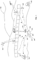
- the system 100 is configured for facilitating guarding of a particular perimeter, for example defending the perimeter against infiltration, and the plurality of launchers 300 (individually designated as 300a, 300b, 300c, etc.) are deployed along the perimeter.
- a perimeter may be a political border 900 between the host nation 910 on which the launchers are deployed and a neighboring nation or other geographical/geopolitical entity 930 which may be hostile or harbor hostile or undesirable elements with respect to the host nation 910.
- Each launcher 300 has an associated radius of operation R, which can be understood to refer to a characteristic range of the respective UAV 400, attained after a predetermined elapsed time t from launch from the respective launcher 300.
- the elapsed time t may thus be regarded as a desired response time for the UAV to reach a particular location.
- the various launchers 300 are spaced from one another and from the border such that each radius of operation R (individually designated as Ra, Rb, Rc, etc. respectively corresponding to the respective launchers 300a, 300b, 300c, etc.) overlap with the border 900, and also with respect to one another at least close to the border 900, as illustrated in Fig. 5 .
- the control center 200 is also located in the host nation 910 (although in variations of this embodiment it may be elsewhere, for example airborne or at sea in neutral or international areas), but may be further distanced from the border 900, for example for site security considerations, particularly if the border zone in the vicinity of the border 900 is hostile.
- the border 900 may comprise a fence or wall 920, comprising sensors 925 including proximity sensors and/or breaching sensors, respectively configured for sensing proximity of a foreign object (for example a body or vehicle) to the wall and for sensing breaches in the wall, and a communication module 930 for transmitting to the control center 200 sensor data indicative of such proximity or breach when such an event happens.
- sensors 925 including proximity sensors and/or breaching sensors, respectively configured for sensing proximity of a foreign object (for example a body or vehicle) to the wall and for sensing breaches in the wall
- a communication module 930 for transmitting to the control center 200 sensor data indicative of such proximity or breach when such an event happens.
- all the launchers 300 are substantially similar to one another, at least in terms of the type of launching systems provided, and the type of UAV launched by each housing 310, and may also be similar to one another in having the same number of launch housings 310 per launcher, though in alternative variations of this embodiment, each launcher may have a number of launch housings that may the same or different with respect to the other launchers 300. In yet other variations of this embodiment, each launcher may be different from the other launchers, in terms of type of launching systems provided, and/or in terms of the type of UAV launched by each housing 310 of the launcher, and/or in terms of the number of launch housings 310 per launcher 300, and so on. Accordingly, the radius of operation R associated with each launcher 300 may be different from one another between the different launchers 300.
- a number of launchers 300 are in communication with the control center 200 via wireless transmitters 292, while other launchers 300 are in communication with the control center 200 via cables 295.
- step 810 the control center 200 receives intelligence data of a possible incursion or infiltration of the border 900 at a particular target zone at location A, for example via sensors 925.
- intelligence data may originate from one or a combination of the following sources: human intelligence, electronic intelligence, satellite surveillance, etc.
- the CC Module 210 makes a command decision at 805 whether or not to investigate further, and in the affirmative, a command signal CS is sent out in step 820 to one or more launchers 300 for one or more UAV's to be launched.
- the command signal CS is for launching a single UAV from the launcher closest to the location A, or if the launchers 300 have different UAV capabilities to one another, the launcher having the shortest response time T to the location A.
- the particular UAV 400 is automatically launched by the respective launcher 300 responsive to receiving the command signal CS and the UAV is automatically flown (by computer control) or manually flown (by UAV operator 205) to location A, with the respective imaging system 410 aboard the UAV 400 scanning the target area around the location A for signs of a candidate target such as an intruder.
- the next step 830 is to identify the target, and this is followed by decision node 840 - whether this identified target warrants further tracking or not.
- the target is a human infiltration agent, for example an intruder such as a potential terrorist, illegal alien, smuggler, thief, foreign troops, etc., for example, tracking of the target is continued, while if it turns out that the target is a border guard, a tourist, an animal etc., for example, or it may be decided that the target does not warrant further tracking.
- the target may be a non-human infiltration target, for example a dangerous animal (e.g., an animal suspected of carrying rabies or an infectious disease), or the target may be a non-human agent such as for example a non-authorized UAV or unmanned land or sea vehicle.
- the UAV maintains aerial surveillance of the target, in general by maintaining the target within the field of view FOV of the imaging system 410.
- Further tracking can be manually performed, for example by the UAV operator 205 controlling the UAV in cooperation with the payload (imaging system) operator 206 (which in at least some embodiment may be the same operator), typically at the control center 200 though the operator 206 may be stationed at a different location and communicates with the UAV to control operation thereof via suitable communication means.
- the payload operator 206 which in at least some embodiment may be the same operator
- the tracking may be automated, for example by means of a suitable computerized system and/or an electro-optical auto tracking system.
- the fact, details and other data of the target, including its location in real time, may be relayed by the control center to any desired party, for example ground forces such as border patrol, police etc. that are responsible for confronting and dealing with the target.
- tracking may be terminated, for example when suitable ground forces such as border patrol, police etc. arrive at the location of the target, which has been continuously tracked and relayed to the ground forces via control center 200 by the UAV, and the ground forces may then deal with the target, for example by neutralizing or apprehending any potential threat.
- the ground forces may include one or more of personnel and vehicles (manned or unmanned), and/or air vehicles and/or sea vehicles as appropriate.
- step 870 the UAV is recovered.
- the UAV may be flown to a recovery site, where it is landed and refurbished, to be subsequently re-used in the original or a different launcher 300 when needed.
- another UAV 400 may be automatically launched from the same or a different launcher 300 in response to receiving a suitable command signal to take over or to assist tracking of the target. This may occur, for example, when the original UAV is damaged, or when the original UAV lacks sufficient fuel or electrical power to maintain tracking operation. In such cases, the operational status of the original UAV is monitored, and the next UAV is launched such that its response time T is less than the estimated time to failure of the original UAV. Thus, location data of the original UAV is used to guide the second UAV to the target and take over tracking, such that tracking and surveillance of the target is effectively continuous and uninterrupted.
- a number of UAV's may be launched sequentially or substantially concurrently in step 820. This may provide multiple redundancy in tracking - for example if one UAV suddenly fails the other UAV's can still provide tracking data. Alternatively, it may turn out that what was initially considered to be a single target is in fact a group of targets that may potentially scatter in different directions, and thus the multiple UAV's may provide tracking of each separate target if there are sufficient targets launched (of course, once the target is identified in step 830 as comprising multiple targets, additional UAV's may be automatically launched and homed in to their location via the data provided by the first UAV. Alternatively, and depending on the terrain on which the target is located, it may be possible for the target to enter a structure having multiple exits, and the strategic solution for ensuring continuation of surveillance is to cover all the exits by providing a UAV to survey each such exit.
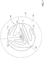
- step 820 In another variation of step 820, designated as step 820' in Fig. 8(a) , three UAV's (designated with reference numerals 400a, 400b, 400c) are launched in response to the command signal CS, and is particularly useful where the exact location of the suspected target T is not known with certainty and/or where it is suspected or known that the suspected target T may move quickly from the last known location within the time taken for the nearest UAV to arrive at this location.
- two UAV's or alternatively more than three UAV's may be launched in step 420' instead of three.
- a probability zone PZ may be defined around the last known location of the suspected target T, or centered around the area where the suspected target is general located.
- perimeter P is displaced by a dimension S from the center C of the probability zone PZ such that the perimeter P defines a threshold beyond which it is considered unlikely (within a predefined probability which may differ from case to case) that the suspected target will have traveled, even if traveling at a known, predicted or estimated maximum speed, irrespective of direction, in the time period between detection of the target and the arrival of at least one of the UAV's.
- the shape of the probability zone PZ is illustrated as circular, it is not necessarily so, and the probability zone may take on any suitable shape, which may generally depend on the nature of the suspected target, its means of mobility, and the nature of the terrain.
- step 820' the three UAV's are launched, each one to a different part of the probability zone PZ.
- UAV 400a and UAV 400b are each directed to generally opposed extremities, target points La and Lb respectively, of the probability zone PZ at the perimeter P, while the third UAV 400c is directed to a target point Lc at or near the center C of the zone.
- the three UAV's may be launched from the same launcher 300 or from different launchers 300, optimally according to availability of UAV's in each launcher and according to satisfying the criteria of minimizing the response time of each UAV to its designated target point.
- La and Lb may lie along the generally direction that the target was observed to be traveling when detected.
- La and/or Lb and/or Lc may be locations in the probability zone PZ having relative high probability of finding the suspected target there. If the suspected target is located by one of the UAV's, steps 830 to 870 may be implemented with respect to this UAV, and the other two UAV's may be recovered as per step 870, or at least one of these two UAV's may be used to provide multiple redundancy in tracking, as disclosed above, mutatis mutandis.
- step 825' is then implemented, in which the probability zone PZ is split into three search zones Za, Zb, Zc, one zone for each UAV, and which each UAV 400a, 400b, 400c implements a search-and-locate mission M in its respective zone Za, Zb, Zc ( Fig. 7 ).
- each mission M may follow a zigzag path that eventually covers the full respective zone such that the zone comes under observation by the respective imaging system 410 of the respective UAV.
- the probability zone PZ is not necessarily of a static and fixed form. For example, if further intelligence data regarding the suspect target is received while the UAV's are on their way to the probability zone PZ or while they are carrying out their missions M, the shape and extent of each respective zone Za, Zb, Zc may be changed, as well as the number of zones searched and/or the form of the mission M changed. Additionally or alternatively, if the suspected target is not detected within a particular time, it may be necessary to expand and/or displace the probability zone PZ to account for the possibility that the suspected target may have traveled further and out of the probability zone PZ. One possible way to address the expanded probability zone PZ is by extending each mission M accordingly.
- Another way is to define a new search zone Zx between the original perimeter P of the probability zone PZ and the expanded perimeter P' of the expanded probability zone PZ, and to launch one or more additional UAV's to search this zone Zx.
- this process may be repeated as often as necessary, each time expanding the probability zone PZ as required.
- each group operating with respect to a respective different probability zone.
- a UAV of one group happens to be closer to a target zone of one particular probability zone than the original UAV that was dispatched to that zone.
- launching a new UAV to a particular target zone it may be possible to divert a UAV, that was originally deployed for a different probability zone, to the aforesaid target zone.
- the respective UAV's 400 may at least in some cases be tactical, mini- or micro- UAV's and/or operated from high altitudes such as to minimize the probability of being detected in flight by the suspected target, and thus reduces the probability of the suspected target from taking evasive action to avoid detection or being tracked.
- such small-sized UAV's may be maneuvered through confined spaces, for example wooded areas and urban areas in a fast, slow or hovering flight, and in a controllable manner, at least in some cases with greater effectiveness, more safety and lower probability of detection than would be the case with manned air vehicles.
- UAV's may be used where endurance may be required - for example where it is expected that the ground forces cannot arrive and take over for long periods.
- one or a plurality of launchers 300 may be provided atop masts or rooftops in an urban zone.
- a launcher 300 may be installed on a rooftop of a building housing a bank and/or of a nearby building or at any other strategic locations.
- the launcher 300 automatically launches one or more UAV's which can then follow the getaway vehicle used by the criminals until a helicopter can take over surveillance and/or until the vehicle is apprehended.
- the command signal for activating the system 100 and launching the UAVs may be generated and transmitted, for example automatically on activation of the bank alarm system, or via a coded signal sent directly by lawenforcement agents in the area.
- one or a plurality of launchers 300 may be additionally or alternatively provided atop vehicles, for example law enforcement vehicles or military vehicles, which may be moving such as on patrol.
- vehicles for example law enforcement vehicles or military vehicles, which may be moving such as on patrol.
- a UAV from such a vehicle is launched responsive to receiving the command signal CS from the control center 200.
- one or a plurality of launchers 300 may optionally be provided atop vehicles, for example emergency and rescue forces vehicles (e.g., fire fighters, environmental agencies etc), which may be deployed to answer an emergency situation.
- a UAV 400 from such a vehicle (and/or from static locations such as illustrated in Fig. 1 , for example) may be launched responsive to receiving the command signal CS from the control center 200.
- the launcher 300 may stay on the vehicle or may be removed and re-positioned for later usage.
- the UAV may include as payload, in addition to or instead of the image sensor, a contamination sensor configured for detecting and/or identifying toxic or otherwise dangerous chemical, biological, radiological or nuclear agents, and the UAV is operated to fly into a target zone that is suspected to include such agents.
- a target zone may be associated with a perimeter defining the site of an attack, or may be a building or complex that stores or processes such agents, and the target zone may include a body of such agents, for example smoke or a cloud of particulate matter, or precipitation or a mist, for example.
- the UAV then uses the contamination sensor to collect and identify any possible contaminants at the target zone, and to enable associated risks to be evaluated.
- the UAV may stay airborne and track the movement of the body of agents, until they are sufficiently dispersed as to be rendered harmless, or until other resources may be brought into play to deal with the contamination.
- a plurality of UAV's may be launched to monitor and track the body of agents if this expands or moves in multiple directions at the same time.
- the suspected contamination agents operate as infiltration agents at the target zone.
Landscapes
- Engineering & Computer Science (AREA)
- General Engineering & Computer Science (AREA)
- Chemical & Material Sciences (AREA)
- Aviation & Aerospace Engineering (AREA)
- Combustion & Propulsion (AREA)
- Eye Examination Apparatus (AREA)
- Data Exchanges In Wide-Area Networks (AREA)
- Photoreceptors In Electrophotography (AREA)
- Traffic Control Systems (AREA)
- Control Of Position, Course, Altitude, Or Attitude Of Moving Bodies (AREA)
- Selective Calling Equipment (AREA)
- Debugging And Monitoring (AREA)
- Radar Systems Or Details Thereof (AREA)
- Telephonic Communication Services (AREA)
Description
- This invention relates to systems employing UAV's and corresponding methods of operating UAV's, in particular relating to deployment of UAV's.
- Unmanned Air Vehicles (UAV) are well known and have many uses, which may include active surveillance or over-the-hill data gathering.
- For example, by way of general background interest, the following publications disclose various UAV configurations:
-
EP 1884463 discloses a Micro Air-Vehicle (MAV) starting system that provides the combined functions of: packing protection of sensitive vehicle components, a mechanical starting assembly, and a launch pad. The disclosed preferred embodiment comprises a container and a container lid with the MAV clamped to the lid. Also disposed on the container lid is a starting assembly. The lid which doubles as a launching pad with the attached MAV is removed from the container, placed on the ground, the MAV is started with the starling mechanism and launched. -
US 7,089,843 discloses a launcher including a plurality of launch tubes for stowing and launching a plurality of air vehicles. A central air manifold is operatively connected to an air storage tank; a first launch tube air manifold is operatively connected to a first group of the launch tubes and operatively connected to the central air manifold. The first launch tube air manifold has a separate port corresponding to each launch tube of the first group of launch tubes. A release valve mechanism is removably mounted in one of the ports of the first launch tube air manifold, the release valve mechanism controlling the passage of launch air between the first launch tube air manifold and the launch tube corresponding to the port in which the release valve mechanism is mounted. A plug is removably mounted in each of the ports not occupied by the release valve mechanism. -
US 6,119,976 discloses a shoulder launched unmanned reconnaissance system for providing overhead visual surveillance of remote targets is disclosed. The system includes a reconnaissance air vehicle which may be fired from a portable launcher, accelerated to flight speed, and remotely controlled using a ground control system. The vehicle is flown to the target area to enable an onboard wide angle video system to transmit video images of the target to the ground control system for processing and display. The ground control system enables the reconnaissance vehicle to be flown to a recovery area and to descend in a stall mode after the flight is completed for maintenance prior to reuse. The air vehicle includes collapsible wings which are deployable after launch by a spring actuated mechanism. -
US 2009/015460 A1 discloses a method for determining whether a target is of interest, wherein a radar system is used for developing a topographic map of the target area. The radar is then used for detecting and tracking targets which move through the target area. -
WO 2008/085536 A2 discloses a system for reconnaissance comprising an unmanned airborne vehicle which is composed of a fixed wing airplane which is propelled by individual UAVs that are attached to the fixed wing. The fixed wing airplane serves as fuel tank for the individual UAVs. - Other known UAV systems include, for example, the "MAV" system by Aerovironment, and the "Train Cable UAV" by Planum Vision.
- The invention is defined in the appended claims. According to the invention there is provided a method for guarding a perimeter, comprising:
- (a) providing infiltration information of an actual or suspected infiltration at a location target zone associated with said perimeter by at least one infiltration agent;
- (b) deploying at least one ready-to-launch UAV to said target zone responsive to receiving said infiltration information;
- (c) operating said at least one UAV to search a target area around said target zone to thereby locate and home onto at least one said infiltration agent; and
- (d) at least one of:
- identifying nature of at least one said homed-onto infiltration agent or nature of said infiltration via said at least one UAV and providing data corresponding to said nature; and
- tracking at least one said homed-onto infiltration agent via said at least one UAV and providing data corresponding to a location of said homed-onto infiltration agent to enable neutralization thereof.
- Herein, "guarding" includes, inter alia, one or more of watching, sensing, detecting, data gathering, and so on relating to unwanted and/or unexpected and/or unauthorized and/or hostile and/or dangerous infiltration agents (human and/or non-human), as well as relating to such agents and/or one or more of defending, protecting against, preventing intrusion by, controlling a location with respect to, securing against, providing safety from, such agents.
- For example, step (b) may comprise speed-launching at least one ready-to-launch UAV in a trajectory or along any suitable flight path to said target zone responsive to receiving said infiltration information
- The method according to invention includes the following features.
- Wherein said at least one supplemental UAV may be speed launched in step (d) for supplementing said identification in step (I), and/or said tracking in step (II), or taking over said identification and/or said tracking, respectively, from said UAV previously launched in step (b).
- In order to understand the invention and to see how it may be carried out in practice, embodiments will now be described, by way of non-limiting example only, with reference to the accompanying drawings, in which:
-
Fig. 1 schematically illustrates a system according to an embodiment of the invention. -
Fig. 2 illustrates an embodiment of a UAV launcher. -
Fig. 3 illustrates an embodiment of a UAV. -
Fig. 4 illustrates another embodiment of a UAV launcher. -
Fig. 5 schematically illustrates an application of the embodiment ofFig. 1 . -
Fig. 6 schematically illustrates another application of the embodiment ofFig. 1 . -
Fig. 7 schematically illustrates another application of the embodiment ofFig. 1 . -
Fig. 8 schematically illustrates a method according to an embodiment of the invention;Fig. 8(a) schematically illustrates a variation of the embodiment ofFig. 8 . - Referring to
Figs. 1 to 3 , a multi-purpose UAV deployment system according to a first embodiment of the invention, generally designated 100, comprises acontrol center 200 and a plurality ofUAV launchers 300. - Referring to
Fig. 2 , eachlauncher 300 is configured for speed-launching at least oneUAV 400 in an automated manner in response to receiving a control command signal to do so, and thus eachlauncher 300 is configured for operating unattended. In the embodiment illustrated inFig. 2 , thelauncher 300 is configured for speed-launching one or a plurality of UAV's and comprises a plurality oflaunch housings 310, eachlaunch housing 310 housing aUAV 400, which in operation of therespective launch housing 400 is in a ready for launch mode (RFL mode). In alternative variations of this embodiment, at least one launcher is configured for speed-launching one UAV and comprises a respective launch housing. Thelaunch housing 310 further comprises a suitable launching system (not shown) configured for imparting a forward momentum to therespective UAV 400 sufficient to enable the UAV to become airborne and subsequently be capable of maintaining flight under its own power after exiting therespective launch housing 310. For example, the launching system may be configured for launching the respective UAV via any suitable pneumatic, hydraulic, pyrotechnic, elastic, mechanical or other arrangement. - In alternative variations of this embodiment, the
launch housing 310 does not comprise any specific mechanism or arrangement to eject and push out therespective UAV 400 therefrom for launching the same. Rather, the UAV 400 is itself configured for exiting thelaunch housing 310 under its own power - for example the UAV may have VTOL, STOL or V/STOL capabilities, and/or may comprise auxiliary power packs (e.g. rocket assisted take-off systems). - The
launcher 300 further comprises asuitable communication system 350, comprising at least a receiver for receiving command signals transmitted by thecontrol center 200. In this embodiment, thecommunication system 350 also comprises a transmitter for transmitting signals at least to thecontrol center 200. Furthermore, thelauncher 300 may comprise acontrol unit 390, such as for example a microprocessor, for controlling operation thereof. - In this embodiment, the
communication system 350 is wireless, for example operatively connected to thecontrol center 200 wirelessly via a radio transmitter using any suitable radio band, either directly, or via a system of relay stations and/or via satellite connection. In alternative variations of this embodiment,communication system 350 may be cable-based, and is operatively connected to thecontrol center 200 via a cable network, or is based on laser communication or fiber optics, or comprises a combination of different communications media, for example. - The
launcher 300 in this embodiment comprises apointing mechanism 360, which is configured for enabling the azimuth and/or elevation of therespective launch housings 310 to be selectively controlled, thereby providing any desired or optimal launch direction LD for thelaunch housings 310. Further, thelauncher 300, while in use is typically statically deployed at a fixed geographical location in this embodiment, is readily transportable to a different geographical location when desired, by means oftrailer 370, which can be pulled by any suitable vehicle, for example. In alternative variations of this embodiment, at least onelauncher 300 is permanently deployed at one geographical location in a fixed permanent installation, while in these or other alternative variations of this embodiment, at least onelauncher 300 may be self-propelled, for example affixed on a carrier vehicle, which may be, for example, a land vehicle, a sea-faring vehicle, an amphibious vehicle, a hovercraft, etc. In alternative variations of this embodiment, at least onelauncher 300 does not comprise a pointing mechanism, and is permanently pointing in one direction, at least relative to the launcher base. - The
launcher 300 further comprises a GPS or any other suitable global positioning system, and furthermore thecontrol unit 390 is configured for operating thecommunication system 350 to send a signal to thecontrol center 200 advising the same of the geographical position of therespective launcher 300 according to its GPS location. Alternatively, the position of therespective launcher 300 may be determined manually, and relayed to thecontrol center 200 by personnel such as for example the ground crew responsible for deploying thelauncher 300. - After deployment, the
launcher 300 is configured for operating in an automated manner, without the need for any ground crew. A ground crew may be provided from time to time for repair, maintenance and refurbishment, but operation of thelauncher 300 for launching the respective UAV's is generally automated and responsive to receiving suitable control signals to this effect from thecontrol center 200. - In these or other alternative variations of this embodiment, one launch housing may be used to launch multiple UAV's, which may be stored one behind another serially in the launch housing, or may be stored one above another in the launch housing, or may be loaded one at a time to the launch housing using a suitable loading mechanism. For example, referring to
Fig. 4 , at least one launcher according to a different embodiment, and designated with the reference numeral 300', comprises one or more multiple launch housings 310' mounted onto a pointing mechanism 360', and also comprisescontrol unit 390' configured for operating the communication system 350'. Each such multiple launch housing 310' comprises a launch tube 320' configured for speed launching a UAV, and a UAV magazine 370' comprising a plurality of UAV's 400 in stacked arrangement, and configured for loading each UAV from the magazine 350' in turn to the launch tube 320' after the previous UAV has been launched. - Referring again to
Fig. 1 , thecontrol center 200 comprises a suitable command and control module 210 (CC Module), which in operation may be configured for processing intelligence data ID and deciding whether or not to launch one or more UAV's 400, from one ormore launchers 300, and in which direction and towards which particular target zone. TheCC Module 210 in operation is further configured for processing surveillance and other data provided by the launched one or more UAV's 400, and for passing on such surveillance and other data and/or analysis thereof to another party. Thecontrol center 200 further comprises asuitable communication system 250, comprising at least a transmitter for transmitting command signals to thelaunchers 300. In this embodiment, thecommunication system 250 also comprises a receiver for receiving signals from at least thelaunchers 300. Furthermore, thecontrol center 200 comprises acontroller 290, such as for example a microprocessor, for controlling operation thereof. - In this embodiment, the
communication system 250 is wireless, for example operatively connected to thelaunchers 300 wirelessly via a radio transmitter using any suitable radio band, either directly, or via a system of relay stations and/or via satellite connection. In alternative variations of this embodiment,communication system 250 may be cable-based, and is operatively connected to thelaunchers 300 via a cable network, or is based on laser communication, fiber optics or any other suitable means of communication, or comprises a combination of different communications media, for example. - The
control center 200 is in operation further configured for receiving intelligence data ID, and may do so in one or more forms. In particular, such data ID may include a suspected location of a target that it is desired to identify and/or track. Such data may include human intelligence, forexample observers 490 in the field may spot a suspected target T and radio or otherwise advise thecontrol center 200 of the fact and location of the suspected target T. - Where the
system 100 is used for guarding a perimeter against infiltration, wherein the target is an infiltrator, additionally or alternatively, breaches in the perimeter (e.g., a fence, wall, etc.) may be sensed optically and/or thermally and/or by sound and/or by touch/movement and/or electronically, and data indicative of the breach is suitably transmitted to thecontrol center 200. Additionally or alternatively, human intelligence data may include data of a possible infiltration at a particular time and/or place, and this data is suitably transmitted to thecontrol center 200. - Additionally or alternatively, the
control center 200 may comprise a receiver for receiving satellite intelligence data from asatellite network 492, for example satellite image data (visible spectrum, infra red, etc) of a particular target zone at a particular reference time, and this image data may be analyzed to provide such intelligence data to thecontrol center 200. Additionally or alternatively, thecontrol center 200 comprises or is operatively connected to a suitable sensing module, for example any suitable SIGINT module for intercepting signals, optionally including at least one of an ELINT module and a COMINT module. - Additionally or alternatively, the
control center 200 comprises a suitable detection system 270 (which may comprise, for example, a suitable radar system and/or a suitable ground based electro optic system) operatively connected thereto for detecting a target T within a particular radius of operation, around thecontrol center 200 and/or around one or more additional zones, wherein a number of linked radar systems and/or ground based electro-optic systems may be provided for radar coverage thereof. - In this embodiment, the
CC Module 210 is in the form of one or more human operators, skilled at receiving and analyzing the aforesaid intelligence data, and at deciding whether to launch one or more said UAV from one or more launchers. Thecontroller 250 may assist the human controller by highlighting the closest launcher available and ready for launch with respect to a particular target. - In alternative variations of this embodiment, the
CC Module 210 may be fully automated and thus comprises a suitable computer system that is configured for initiating a launch of a UAV based on predetermined parameters. - In this embodiment, the
control center 200 is at a geographically fixed, static location, at least during operation thereof. In alternative variations of this embodiment, thecontrol center 200 may be comprised in a mobile platform - for example transported by means of a vehicle (e.g., carried by the vehicle or towed as a trailer by the vehicle), and the vehicle may be, for example, a land vehicle, a sea-faring vehicle, an amphibious vehicle, a hovercraft, etc, or for example carried by personnel - and thecenter 200 may be operated also when mobile. - Referring to
Fig. 3 , each saidUAV 400 is configured as a non-tethered vehicle in the form of a steerable airborne platform comprising at least one sensor system configured at least for enabling a target within the sensor's field of view FOV to be identified. In this embodiment, the sensor system comprises asuitable imaging system 410 configured for providing in real time a video stream in the visible spectrum, and may be further configured for providing corresponding infrared images and/or comprises enhanced night vision features. In alternative variations of this embodiment, the imaging system may additionally or alternatively comprise a Synthetic Aperture Radar (SAR) and/or any other suitable sensor system. - The
imaging system 410 may comprise a suitable camera, preferably an electronic camera, preferably mounted to theUAV 400 via a stabilizing platform such as to compensate for vibration etc, and thus provide stable images to thecontrol center 200 viacommunications module 420. TheUAV 400 comprises asuitable propulsion unit 430, which may be electrically powered, or fuel powered, or a hybrid, for example, for providing powered flight and/or VTOL capability to the UAV. Preferably, theimaging system 410 comprises apointing mechanism 412 which is configured for enabling the azimuth and elevation of theimaging system 410 to be selectively controlled, thereby providing any desired line of sight (LOS) for the imaging system within a defined field of regard FOR. Further, the imaging system may be configured for providing a variety of magnifications, and/or fields of view (FOV). Such imaging systems are well known in the art. - According to one aspect of the invention, the
UAV 400 may be based on any suitable micro-UAV's, for example the "Mosquito" UAV, produced by Israel Aerospace Industries Ltd, Israel. According to another aspect of the invention, theUAV 400 may be based on any suitable mini-UAV's, for example the Birdeye family of UAV's, produced by Israel Aerospace Industries Ltd, Israel. According to another aspect of the invention, theUAV 400 may be based on any suitable larger UAV's, for example the I-View UAV's, produced by Israel Aerospace Industries Ltd, Israel. - The
UAV 400 is configured for being automatically launched from itsrespective housing 310 when in the aforesaid RFL mode, in which therespective UAV 400 is fuelled and/or has sufficient electrical power to enable operation of the propulsion system and for powering the additional on-board systems, for example theimaging system 410 andcommunications module 420. At least in this embodiment, each operative said launcher comprises at least one said UAV in RFL mode, and may have additional said UAV's in RFL mode, and/or is configured for placing more said UAV's in RFL mode in an automated manner. - Once launched, the UAV may be steered to the desired location in any number of ways. For example, the UAV may receive a particular flight plan to the target zone while still in the launcher housing prior to launch via a suitable communication, or may up-load the flight plan after launch via suitable data-link. Additionally or alternatively, the UAV may be pre-programmed with a plurality of flight plans, for example one each to particular predetermined target zones, and the desired flight plan is brought on-line in the UAV. Alternatively, the UAV is steered manually to the target zone via a
UAV operator 205. - In variations of this embodiment where the launched
UAV 400 comprised a payload, for example the imaging system or other payload, the payload may be operated by means of apayload operator 206, who optionally may also be theUAV operator 205. - In this embodiment, the
payload operator 206 and theUAV operator 205 are comprised in thecontrol center 200, and are located in the same location. In alternative variations of the embodiment, thepayload operator 206, and/or theUAV operator 205, may be independent of thecontrol center 200 and may be located at different geographical locations. - In this embodiment, the
UAV 400 further comprises a suitable GPS or the like, and thecommunication module 420 is configured for transmitting the geographical location of theUAV 400 to thecontrol center 200. Furthermore, thecommunication module 420 may further transmit the direction of the LOS ofimaging system 410 with respect to datum coordinate system UCS of the UAV, the UAV's direction and altitude, and the attitude of coordinate system UCS with respect to an Earth-based coordinate system ECS such as used by the GPS system, and may also further transmit data regarding the magnification of image and other optical parameters. With this data it is possible to then calculate the position and thus the geographical location (with respect to the aforesaid Earth-based coordinate system) of whatever object is in the field of view FOV of theimaging system 410. - Furthermore, the
communication module 420 is also configured for providing identification data for therespective UAV 400, for example an IFF or IP code, so that data received from each UAV by thecontrol center 200 can be associated with itsrespective UAV 400. - In one application of the first embodiment, and referring to
Fig. 1 , thesystem 100 is configured for facilitating guarding of a particular perimeter, for example defending the perimeter against infiltration, and the plurality of launchers 300 (individually designated as 300a, 300b, 300c, etc.) are deployed along the perimeter. For example such a perimeter may be apolitical border 900 between thehost nation 910 on which the launchers are deployed and a neighboring nation or other geographical/geopolitical entity 930 which may be hostile or harbor hostile or undesirable elements with respect to thehost nation 910. Eachlauncher 300 has an associated radius of operation R, which can be understood to refer to a characteristic range of therespective UAV 400, attained after a predetermined elapsed time t from launch from therespective launcher 300. The elapsed time t may thus be regarded as a desired response time for the UAV to reach a particular location. In this embodiment, thevarious launchers 300 are spaced from one another and from the border such that each radius of operation R (individually designated as Ra, Rb, Rc, etc. respectively corresponding to therespective launchers border 900, and also with respect to one another at least close to theborder 900, as illustrated inFig. 5 . - The
control center 200 is also located in the host nation 910 (although in variations of this embodiment it may be elsewhere, for example airborne or at sea in neutral or international areas), but may be further distanced from theborder 900, for example for site security considerations, particularly if the border zone in the vicinity of theborder 900 is hostile. - The
border 900 may comprise a fence orwall 920, comprisingsensors 925 including proximity sensors and/or breaching sensors, respectively configured for sensing proximity of a foreign object (for example a body or vehicle) to the wall and for sensing breaches in the wall, and acommunication module 930 for transmitting to thecontrol center 200 sensor data indicative of such proximity or breach when such an event happens. - In this embodiment, all the
launchers 300 are substantially similar to one another, at least in terms of the type of launching systems provided, and the type of UAV launched by eachhousing 310, and may also be similar to one another in having the same number oflaunch housings 310 per launcher, though in alternative variations of this embodiment, each launcher may have a number of launch housings that may the same or different with respect to theother launchers 300. In yet other variations of this embodiment, each launcher may be different from the other launchers, in terms of type of launching systems provided, and/or in terms of the type of UAV launched by eachhousing 310 of the launcher, and/or in terms of the number oflaunch housings 310 perlauncher 300, and so on. Accordingly, the radius of operation R associated with eachlauncher 300 may be different from one another between thedifferent launchers 300. - In this application of the first embodiment, a number of
launchers 300 are in communication with thecontrol center 200 viawireless transmitters 292, whileother launchers 300 are in communication with thecontrol center 200 viacables 295. - In one method of operation of the
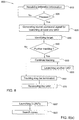
system 100, designated withreference numeral 800 and referring also toFig. 8 , instep 810 thecontrol center 200 receives intelligence data of a possible incursion or infiltration of theborder 900 at a particular target zone at location A, for example viasensors 925. Alternatively, such data may originate from one or a combination of the following sources: human intelligence, electronic intelligence, satellite surveillance, etc. TheCC Module 210 makes a command decision at 805 whether or not to investigate further, and in the affirmative, a command signal CS is sent out instep 820 to one ormore launchers 300 for one or more UAV's to be launched. In the simplest implementation ofstep 820, the command signal CS is for launching a single UAV from the launcher closest to the location A, or if thelaunchers 300 have different UAV capabilities to one another, the launcher having the shortest response time T to the location A. Theparticular UAV 400 is automatically launched by therespective launcher 300 responsive to receiving the command signal CS and the UAV is automatically flown (by computer control) or manually flown (by UAV operator 205) to location A, with therespective imaging system 410 aboard theUAV 400 scanning the target area around the location A for signs of a candidate target such as an intruder. - When a candidate target has been acquired, e.g. detected digitally or in any other suitable manner and homed onto, the
next step 830 is to identify the target, and this is followed by decision node 840 - whether this identified target warrants further tracking or not. For example if the target is a human infiltration agent, for example an intruder such as a potential terrorist, illegal alien, smuggler, thief, foreign troops, etc., for example, tracking of the target is continued, while if it turns out that the target is a border guard, a tourist, an animal etc., for example, or it may be decided that the target does not warrant further tracking. On the other hand, the target may be a non-human infiltration target, for example a dangerous animal (e.g., an animal suspected of carrying rabies or an infectious disease), or the target may be a non-human agent such as for example a non-authorized UAV or unmanned land or sea vehicle. In any case, if further tracking is required, then instep 850 the UAV maintains aerial surveillance of the target, in general by maintaining the target within the field of view FOV of theimaging system 410. - Further tracking can be manually performed, for example by the
UAV operator 205 controlling the UAV in cooperation with the payload (imaging system) operator 206 (which in at least some embodiment may be the same operator), typically at thecontrol center 200 though theoperator 206 may be stationed at a different location and communicates with the UAV to control operation thereof via suitable communication means. - Alternatively, the tracking may be automated, for example by means of a suitable computerized system and/or an electro-optical auto tracking system.
- The fact, details and other data of the target, including its location in real time, may be relayed by the control center to any desired party, for example ground forces such as border patrol, police etc. that are responsible for confronting and dealing with the target.
- In
step 860, tracking may be terminated, for example when suitable ground forces such as border patrol, police etc. arrive at the location of the target, which has been continuously tracked and relayed to the ground forces viacontrol center 200 by the UAV, and the ground forces may then deal with the target, for example by neutralizing or apprehending any potential threat. The ground forces may include one or more of personnel and vehicles (manned or unmanned), and/or air vehicles and/or sea vehicles as appropriate. - In
step 870 the UAV is recovered. For example the UAV may be flown to a recovery site, where it is landed and refurbished, to be subsequently re-used in the original or adifferent launcher 300 when needed. - In a further
optional step 855 prior to step 860, anotherUAV 400 may be automatically launched from the same or adifferent launcher 300 in response to receiving a suitable command signal to take over or to assist tracking of the target. This may occur, for example, when the original UAV is damaged, or when the original UAV lacks sufficient fuel or electrical power to maintain tracking operation. In such cases, the operational status of the original UAV is monitored, and the next UAV is launched such that its response time T is less than the estimated time to failure of the original UAV. Thus, location data of the original UAV is used to guide the second UAV to the target and take over tracking, such that tracking and surveillance of the target is effectively continuous and uninterrupted. - In a variation of this method of operation, a number of UAV's may be launched sequentially or substantially concurrently in
step 820. This may provide multiple redundancy in tracking - for example if one UAV suddenly fails the other UAV's can still provide tracking data. Alternatively, it may turn out that what was initially considered to be a single target is in fact a group of targets that may potentially scatter in different directions, and thus the multiple UAV's may provide tracking of each separate target if there are sufficient targets launched (of course, once the target is identified instep 830 as comprising multiple targets, additional UAV's may be automatically launched and homed in to their location via the data provided by the first UAV. Alternatively, and depending on the terrain on which the target is located, it may be possible for the target to enter a structure having multiple exits, and the strategic solution for ensuring continuation of surveillance is to cover all the exits by providing a UAV to survey each such exit. - In another variation of
step 820, designated as step 820' inFig. 8(a) , three UAV's (designated withreference numerals 400a, 400b, 400c) are launched in response to the command signal CS, and is particularly useful where the exact location of the suspected target T is not known with certainty and/or where it is suspected or known that the suspected target T may move quickly from the last known location within the time taken for the nearest UAV to arrive at this location. In alternative variations of this embodiment, two UAV's or alternatively more than three UAV's may be launched in step 420' instead of three. In such cases, a probability zone PZ may be defined around the last known location of the suspected target T, or centered around the area where the suspected target is general located. Thus, perimeter P is displaced by a dimension S from the center C of the probability zone PZ such that the perimeter P defines a threshold beyond which it is considered unlikely (within a predefined probability which may differ from case to case) that the suspected target will have traveled, even if traveling at a known, predicted or estimated maximum speed, irrespective of direction, in the time period between detection of the target and the arrival of at least one of the UAV's. While the shape of the probability zone PZ is illustrated as circular, it is not necessarily so, and the probability zone may take on any suitable shape, which may generally depend on the nature of the suspected target, its means of mobility, and the nature of the terrain. - In step 820' the three UAV's are launched, each one to a different part of the probability zone PZ. For example: UAV 400a and
UAV 400b are each directed to generally opposed extremities, target points La and Lb respectively, of the probability zone PZ at the perimeter P, while the third UAV 400c is directed to a target point Lc at or near the center C of the zone. The three UAV's may be launched from thesame launcher 300 or fromdifferent launchers 300, optimally according to availability of UAV's in each launcher and according to satisfying the criteria of minimizing the response time of each UAV to its designated target point. - For example, La and Lb may lie along the generally direction that the target was observed to be traveling when detected. Alternatively, La and/or Lb and/or Lc may be locations in the probability zone PZ having relative high probability of finding the suspected target there. If the suspected target is located by one of the UAV's, steps 830 to 870 may be implemented with respect to this UAV, and the other two UAV's may be recovered as per
step 870, or at least one of these two UAV's may be used to provide multiple redundancy in tracking, as disclosed above, mutatis mutandis. - On the other hand, if by the time the three UAV's reach their target points La, Lb, Lc the suspected target is not located by any of the UAV's, step 825' is then implemented, in which the probability zone PZ is split into three search zones Za, Zb, Zc, one zone for each UAV, and which each
UAV 400a, 400b, 400c implements a search-and-locate mission M in its respective zone Za, Zb, Zc (Fig. 7 ). For example, each mission M may follow a zigzag path that eventually covers the full respective zone such that the zone comes under observation by therespective imaging system 410 of the respective UAV. - It is to be noted that the probability zone PZ is not necessarily of a static and fixed form. For example, if further intelligence data regarding the suspect target is received while the UAV's are on their way to the probability zone PZ or while they are carrying out their missions M, the shape and extent of each respective zone Za, Zb, Zc may be changed, as well as the number of zones searched and/or the form of the mission M changed. Additionally or alternatively, if the suspected target is not detected within a particular time, it may be necessary to expand and/or displace the probability zone PZ to account for the possibility that the suspected target may have traveled further and out of the probability zone PZ. One possible way to address the expanded probability zone PZ is by extending each mission M accordingly. Another way is to define a new search zone Zx between the original perimeter P of the probability zone PZ and the expanded perimeter P' of the expanded probability zone PZ, and to launch one or more additional UAV's to search this zone Zx. Of course, this process may be repeated as often as necessary, each time expanding the probability zone PZ as required.
- In some cases, it is possible to concurrently have a number of groups of UAV's, each group operating with respect to a respective different probability zone. In such cases, it is also possible to transfer UAV's from one group to another according to specific needs or requirements. For example, it may be that a UAV of one group happens to be closer to a target zone of one particular probability zone than the original UAV that was dispatched to that zone. In another example, rather than launching a new UAV to a particular target zone it may be possible to divert a UAV, that was originally deployed for a different probability zone, to the aforesaid target zone.
- In these or other applications of the
system 100, the respective UAV's 400 may at least in some cases be tactical, mini- or micro- UAV's and/or operated from high altitudes such as to minimize the probability of being detected in flight by the suspected target, and thus reduces the probability of the suspected target from taking evasive action to avoid detection or being tracked. Furthermore, such small-sized UAV's may be maneuvered through confined spaces, for example wooded areas and urban areas in a fast, slow or hovering flight, and in a controllable manner, at least in some cases with greater effectiveness, more safety and lower probability of detection than would be the case with manned air vehicles. - Additionally or alternatively, at least in some cases larger UAV's may be used where endurance may be required - for example where it is expected that the ground forces cannot arrive and take over for long periods.
- In another application of the
system 100, one or a plurality oflaunchers 300 may be provided atop masts or rooftops in an urban zone. For example, alauncher 300 may be installed on a rooftop of a building housing a bank and/or of a nearby building or at any other strategic locations. In case of a robbery or attempted robbery, thelauncher 300 automatically launches one or more UAV's which can then follow the getaway vehicle used by the criminals until a helicopter can take over surveillance and/or until the vehicle is apprehended. The command signal for activating thesystem 100 and launching the UAVs may be generated and transmitted, for example automatically on activation of the bank alarm system, or via a coded signal sent directly by lawenforcement agents in the area. - In another application of the
system 100, one or a plurality oflaunchers 300 may be additionally or alternatively provided atop vehicles, for example law enforcement vehicles or military vehicles, which may be moving such as on patrol. When required, a UAV from such a vehicle is launched responsive to receiving the command signal CS from thecontrol center 200. - In another application of the
system 100, one or a plurality oflaunchers 300 may optionally be provided atop vehicles, for example emergency and rescue forces vehicles (e.g., fire fighters, environmental agencies etc), which may be deployed to answer an emergency situation. When required, aUAV 400 from such a vehicle (and/or from static locations such as illustrated inFig. 1 , for example) may be launched responsive to receiving the command signal CS from thecontrol center 200. Thelauncher 300 may stay on the vehicle or may be removed and re-positioned for later usage. The UAV may include as payload, in addition to or instead of the image sensor, a contamination sensor configured for detecting and/or identifying toxic or otherwise dangerous chemical, biological, radiological or nuclear agents, and the UAV is operated to fly into a target zone that is suspected to include such agents. Such a target zone may be associated with a perimeter defining the site of an attack, or may be a building or complex that stores or processes such agents, and the target zone may include a body of such agents, for example smoke or a cloud of particulate matter, or precipitation or a mist, for example. The UAV then uses the contamination sensor to collect and identify any possible contaminants at the target zone, and to enable associated risks to be evaluated. Furthermore, the UAV may stay airborne and track the movement of the body of agents, until they are sufficiently dispersed as to be rendered harmless, or until other resources may be brought into play to deal with the contamination. Optionally, a plurality of UAV's may be launched to monitor and track the body of agents if this expands or moves in multiple directions at the same time. - Thus, in this application of
system 100, the suspected contamination agents operate as infiltration agents at the target zone. - In the method claims that follow, alphanumeric characters and Roman numerals used to designate claim steps are provided for convenience only and do not imply any particular order of performing the steps.
- Finally, it should be noted that the word "comprising" as used throughout the appended claims is to be interpreted to mean "including but not limited to".
- The scope of protection of the present invention is defined in the appended claims.
Claims (16)
- A method for guarding a perimeter, comprising:(a) providing infiltration information of an actual or suspected infiltration by at least one infiltration agent at a location of a target zone associated with said perimeter;(b) deploying at least one ready-to-launch UAV (unmanned air vehicle) (400) to said target zone responsive to receiving said infiltration information;(c) operating said at least one UAV (400) to search a target area around said target zone to thereby locate and home onto at least one said infiltration agent; and(d) at least one of:wherein at least one supplemental said UAV (400) is speed launched in step (d) for supplementing said identification in step (I), and/or said tracking in step (II), or taking over said identification and/or said tracking, respectively, from said UAV (400) previously launched in step (b).(I) identifying nature of at least one said homed-onto infiltration agent or nature of said infiltration via said at least one UAV (400) and providing data corresponding to said nature; and(II) tracking at least one said homed-onto infiltration agent via said at least one UAV (400) and providing data corresponding to a location of said homed-onto infiltration agent to enable neutralization thereof,
- Method according to claim 1, wherein step (b) comprises one of:(b1) providing at least one UAV launcher (300), the or each said UAV launcher (300) comprising at least one UAV (400) in ready-to-launch mode, the or each said UAV launcher (300) configured for enabling each respective UAV (400) to be speed launched responsive to receiving said infiltration information; or(b2) providing a plurality of said UAV launchers (300), and, strategically deploying said UAV launchers (300) with respect to said perimeter in a manner allowing each said UAV (400) to reach a predetermined point on said perimeter within a predetermined time after launch.
- Method according to any one of claims 1 to 2, wherein step (a) comprises obtaining infiltration information from at least one of the following sources: human intelligence; human surveillance of said perimeter; electronic intelligence; electronic surveillance of said perimeter; overhead imagery of said perimeter; perimeter breach sensors; radar data; electro-optical and/or infrared surveillance of said perimeter.
- Method according to any one of claims 1 to 3, wherein in step (b) suitable command signals are generated corresponding to said infiltration information and transmitted to at least one said UAV launcher (300) whereby to activate thereby speed-launching of said at least one ready-to-launch UAV (400).
- Method according to any one of claims 1 to 4, wherein said UAV (400) comprises a suitable sensor configured for providing image data or other sensor data within a field of view, and step (c) comprises remotely flying said UAV (400) to said target zone, receiving said image data or said other sensor data generated by said UAV (400) of the target zone, and identifying nature of said infiltration agent in step (I) from said image data or said other sensor data, and wherein optionally step (d) comprises maintaining said infiltration agent within said field of view of said sensor.
- Method according to any one of claims 1 to 5, further comprising step (e), wherein step (e) comprises any one of:- neutralization of said infiltration agent;- neutralization of said infiltration agent comprising intercepting, apprehending or immobilizing said at least one infiltration agent by direct human intervention;- neutralization of said infiltration agent comprising intercepting, apprehending or immobilizing said at least one infiltration agent by direct human intervention, wherein said direct human intervention comprises dispatching to said location one or more of: manned or unmanned ground forces, manned or unmanned airborne forces, and manned or unmanned seaborne forces.
- Method according to any one of claims 1 to 6, wherein step (b) comprises speed-launching a plurality of said ready-to-launch UAV (400), each to a different respective start location in said target zone, responsive to receiving said infiltration information, and searching a respective portion of said target zone for said infiltration agent, and wherein optionally including at least one of the following steps:- wherein at least one of said plurality of said launched UAV's (400) is homed on said infiltration agent in step (c), and at least a first portion of a remainder of said launched UAV's (400) are recovered;- wherein at least one of said plurality of said launched UAV's (400) is homed on said infiltration agent in step (c), and at least a second portion of a remainder of said launched UAV's (400) are maintained airborne for providing supplemental tracking.
- Method according to any one of claims 1 to 7, wherein there are a plurality of infiltration agents, wherein step (b) comprises speed-launching a plurality of said ready-to-launch UAV (400), and in step (c) operating each said UAV (400) to home onto a different said infiltration agent.
- Method according to any one of claims 1 to 8, wherein said data corresponding to said nature in step (d)(I) includes incriminating evidence relating to said nature of said infiltration agent or of said infiltration thereby, and wherein optionally said perimeter constitutes any one of a border between a host country being guarded and a geopolitical entity comprising said infiltration agents prior to said infiltration, or a building or structure; or comprises any one of a fence, wall or line circumscribing an installation; a group of buildings; a complex; a geographical zone.
- Method according to any one of claims 1 to 9, wherein at least one said ready-to-launch UAV's (400) is configured structurally and/or operatively to minimize detection thereof by said infiltration agents.
- Method according to any one of claims 1 to 10, wherein said infiltration agent is one of:- a human agent, wherein said human agent is optionally taken from the group including: terrorist, illegal alien, smuggler, thief, foreign troops.- a non-human agent, wherein said non-human agent is optionally taken from the group of: non-authorized UAV (400), unmanned land vehicle, unmanned sea vehicle, and a contamination agent, optionally taken from the group including: toxic, chemical, biological, radiological or nuclear agents.
- Method according to any one of claims 1 to 11, wherein said infiltration information is indicative of a breach of said perimeter.
- System for guarding a perimeter, comprising:(a) control center (200) configured for generating a control signal responsive to receiving infiltration information of an actual or suspected infiltration at a location of a target zone associated with said perimeter by at least one infiltration agent;(b) launch system configured for deploying at least one ready-to-launch UAV (400) to said target zone responsive to receiving said control signal;(c) at least one controller configured for operating said at least one UAV (400) to search an area around said target zone to thereby locate and home onto at least one said infiltration agent and for at least one of:(i) identifying nature of said infiltration agent or nature of infiltration; and(ii) tracking said infiltration agent via said at least one UAV (400); and(d) communication system (350), configured for providing at least one of:wherein the system is further configured for speed launching at least one supplemental said UAV (400) for supplementing said identification in step (I), and/or said tracking in step (II), or taking over said identification and/or said tracking, respectively, from said UAV (400) previously launched.- data corresponding to said nature in (i); and- location data corresponding to a location of said infiltration agent in (ii) to enable neutralization thereof,
- System according to claim 13, wherein said launch system comprises at least one a UAV launcher (300) remote from said control center (200) and comprising at least one said UAV (400), the or each said UAV launcher (300) being in operation configured for automatically speed-launching at least one said UAV (400) responsive to receiving said launch command signal from said control center (200).
- System according to any one of claims 13 to 14, wherein the or each said UAV (400) comprises at least one of:- a sensor system having a field of view, in operation said UAV (400) being configured for providing sensor data associated with said infiltration agent responsive to said infiltration agent being in said field of view, and wherein optionally said sensor system comprises an image acquisition system for providing images corresponding to said field of view, and wherein optionally said image acquisition system comprises a pointing mechanism for controllably changing a line of sight of said image acquisition system in at least one or azimuth and elevation; and- a GPS or other positioning system configured for providing geographical location data of the respective UAV (400) according to a pre-known coordinate system, and wherein optionally said location data is derived from said geographical location data and from knowledge of the line of sight of the image acquisition system and from knowledge of an altitude of the respective said UAV; and wherein optionally said communication system comprises a communication module (420) comprised in the or each said UAV (400) each said communication module (420) being configured, in operation, for receiving said command signal, for enabling operation of the respective UAV (400) by said controller, and for transmitting sensor data provided by said sensor system; and- a contamination sensor configured for detecting said infiltration agent when in the form of a contaminating agent, and wherein optionally said control center (200) is remote from said launch system; and wherein optionally at least one said UAV launcher (300) is mobile configured for controllably changing its geographical position with respect to at least one of said control center (200) and said perimeter; and wherein optionally said system comprises a plurality of said UAV launchers (300), spaced from one another and at different locations with respect to said perimeter, wherein said control center (200) is configured for providing said launch command signal to a said launcher (300) capable of launching a respective said at least one UAV (400) to minimize said response time.
- System according to any one of claims 14 to 15, wherein said sensor data is transmitted to at least one of said control center (200) and said controller.
Priority Applications (4)
| Application Number | Priority Date | Filing Date | Title |
|---|---|---|---|
| RS20211190A RS62376B1 (en) | 2009-10-22 | 2010-10-19 | Uav system and method |
| HRP20211506TT HRP20211506T1 (en) | 2009-10-22 | 2010-10-19 | SYSTEM AND PROCEDURE FOR UNMANNED AIRCRAFT (UAV) |
| PL10785231T PL2490940T3 (en) | 2009-10-22 | 2010-10-19 | BSP SYSTEM AND METHOD |
| SI201032090T SI2490940T1 (en) | 2009-10-22 | 2010-10-19 | UAV system and method |
Applications Claiming Priority (2)
| Application Number | Priority Date | Filing Date | Title |
|---|---|---|---|
| IL201681A IL201681A (en) | 2009-10-22 | 2009-10-22 | Uav system and method |
| PCT/IL2010/000857 WO2011048591A1 (en) | 2009-10-22 | 2010-10-19 | Uav system and method |
Publications (2)
| Publication Number | Publication Date |
|---|---|
| EP2490940A1 EP2490940A1 (en) | 2012-08-29 |
| EP2490940B1 true EP2490940B1 (en) | 2021-06-30 |
Family
ID=43530835
Family Applications (1)
| Application Number | Title | Priority Date | Filing Date |
|---|---|---|---|
| EP10785231.1A Active EP2490940B1 (en) | 2009-10-22 | 2010-10-19 | Uav system and method |
Country Status (12)
| Country | Link |
|---|---|
| US (1) | US20120210853A1 (en) |
| EP (1) | EP2490940B1 (en) |
| DK (1) | DK2490940T3 (en) |
| HR (1) | HRP20211506T1 (en) |
| HU (1) | HUE056146T2 (en) |
| IL (1) | IL201681A (en) |
| LT (1) | LT2490940T (en) |
| PL (1) | PL2490940T3 (en) |
| RS (1) | RS62376B1 (en) |
| SG (2) | SG10201406819SA (en) |
| SI (1) | SI2490940T1 (en) |
| WO (1) | WO2011048591A1 (en) |
Families Citing this family (83)
| Publication number | Priority date | Publication date | Assignee | Title |
|---|---|---|---|---|
| SG175778A1 (en) | 2009-04-24 | 2011-12-29 | Insitu Inc | Systems and methods for recovering and controlling post-recovery motion of unmanned aircraft |
| US8944373B2 (en) | 2010-09-27 | 2015-02-03 | Insitu, Inc. | Line capture devices for unmanned aircraft, and associated systems and methods |
| KR101157484B1 (en) * | 2010-12-14 | 2012-06-20 | 주식회사 대한항공 | Uav automatic recovering method |
| US9061102B2 (en) | 2012-07-17 | 2015-06-23 | Elwha Llc | Unmanned device interaction methods and systems |
| US10019000B2 (en) * | 2012-07-17 | 2018-07-10 | Elwha Llc | Unmanned device utilization methods and systems |
| US8978534B2 (en) * | 2012-08-23 | 2015-03-17 | Emmanuel Daniel Martn Jacq | Autonomous unmanned tower military mobile intermodal container and method of using the same |
| US9405296B2 (en) | 2012-12-19 | 2016-08-02 | Elwah LLC | Collision targeting for hazard handling |
| US9540102B2 (en) | 2012-12-19 | 2017-01-10 | Elwha Llc | Base station multi-vehicle coordination |
| US9810789B2 (en) | 2012-12-19 | 2017-11-07 | Elwha Llc | Unoccupied flying vehicle (UFV) location assurance |
| US9527586B2 (en) | 2012-12-19 | 2016-12-27 | Elwha Llc | Inter-vehicle flight attribute communication for an unoccupied flying vehicle (UFV) |
| US10279906B2 (en) | 2012-12-19 | 2019-05-07 | Elwha Llc | Automated hazard handling routine engagement |
| US10518877B2 (en) | 2012-12-19 | 2019-12-31 | Elwha Llc | Inter-vehicle communication for hazard handling for an unoccupied flying vehicle (UFV) |
| US9747809B2 (en) | 2012-12-19 | 2017-08-29 | Elwha Llc | Automated hazard handling routine activation |
| US9527587B2 (en) | 2012-12-19 | 2016-12-27 | Elwha Llc | Unoccupied flying vehicle (UFV) coordination |
| US9776716B2 (en) | 2012-12-19 | 2017-10-03 | Elwah LLC | Unoccupied flying vehicle (UFV) inter-vehicle communication for hazard handling |
| US9669926B2 (en) | 2012-12-19 | 2017-06-06 | Elwha Llc | Unoccupied flying vehicle (UFV) location confirmance |
| US9235218B2 (en) | 2012-12-19 | 2016-01-12 | Elwha Llc | Collision targeting for an unoccupied flying vehicle (UFV) |
| US9567074B2 (en) | 2012-12-19 | 2017-02-14 | Elwha Llc | Base station control for an unoccupied flying vehicle (UFV) |
| AU2014293617A1 (en) | 2013-05-03 | 2015-12-03 | Aerovironment, Inc. | Vertical takeoff and landing (VTOL) air vehicle |
| EP3450322A1 (en) * | 2013-09-11 | 2019-03-06 | Silicis Technologies Inc. | Method for commanding and controlling an autonomous flying vehicle |
| US9815684B2 (en) * | 2013-11-01 | 2017-11-14 | Brian Kamradt | Fueling station for unmanned aerial vehicle of the vertical takeoff types |
| EP2879012A1 (en) * | 2013-11-29 | 2015-06-03 | The Boeing Company | System and method for commanding a payload of an aircraft |
| MY184651A (en) * | 2014-01-20 | 2021-04-14 | Pillay Venkateshwara | A system for mapping and tracking ground targets |
| US12271955B2 (en) | 2014-02-28 | 2025-04-08 | Lucas J. Myslinski | Drone device |
| US9643722B1 (en) | 2014-02-28 | 2017-05-09 | Lucas J. Myslinski | Drone device security system |
| US9334052B2 (en) * | 2014-05-20 | 2016-05-10 | Verizon Patent And Licensing Inc. | Unmanned aerial vehicle flight path determination, optimization, and management |
| US9978030B2 (en) * | 2014-06-11 | 2018-05-22 | Hartford Fire Insurance Company | System and method for processing of UAV based data for risk mitigation and loss control |
| US10399674B2 (en) * | 2014-07-28 | 2019-09-03 | Insitu, Inc. | Systems and methods countering an unmanned air vehicle |
| US10163164B1 (en) | 2014-09-22 | 2018-12-25 | State Farm Mutual Automobile Insurance Company | Unmanned aerial vehicle (UAV) data collection and claim pre-generation for insured approval |
| US20160104241A1 (en) * | 2014-10-14 | 2016-04-14 | Linwood Ma | Mobile Securities Trading Platform |
| US9429945B2 (en) * | 2014-10-22 | 2016-08-30 | Honeywell International Inc. | Surveying areas using a radar system and an unmanned aerial vehicle |
| WO2016065625A1 (en) * | 2014-10-31 | 2016-05-06 | SZ DJI Technology Co., Ltd. | Systems and methods for walking pets |
| US9896222B2 (en) | 2014-11-20 | 2018-02-20 | Insitu, Inc. | Capture devices for unmanned aerial vehicles, including track-borne capture lines, and associated systems and methods |
| US10832328B1 (en) | 2014-12-11 | 2020-11-10 | State Farm Mutual Automobile Insurance Company | Smart notepad for improved workflow efficiency for insurance claim associates |
| US10896469B1 (en) * | 2014-12-11 | 2021-01-19 | State Farm Mutual Automobile Insurance Company | Automated caller identification for improved workflow efficiency for insurance claim associates |
| US10832329B1 (en) | 2014-12-11 | 2020-11-10 | State Farm Mutual Automobile Insurance Company | Search tool for improved workflow efficiency for insurance claim associates |
| US10752378B2 (en) * | 2014-12-18 | 2020-08-25 | The Boeing Company | Mobile apparatus for pest detection and engagement |
| US9977435B2 (en) | 2015-02-11 | 2018-05-22 | Aeroviroment, Inc. | Survey migration system for vertical take-off and landing (VTOL) unmanned aerial vehicles (UAVS) |
| US9880563B2 (en) | 2015-02-11 | 2018-01-30 | Aerovironment, Inc. | Geographic survey system for vertical take-off and landing (VTOL) unmanned aerial vehicles (UAVs) |
| US11021266B2 (en) | 2015-02-11 | 2021-06-01 | Aerovironment, Inc. | Pod operating system for a vertical take-off and landing (VTOL) unmanned aerial vehicle (UAV) |
| US10336470B2 (en) | 2015-02-11 | 2019-07-02 | Aerovironment, Inc. | Pod launch and landing system for vertical take-off and landing (VTOL)unmanned aerial vehicles (UAVs) |
| US10850866B2 (en) * | 2015-02-11 | 2020-12-01 | Aerovironment, Inc. | Pod cover system for a vertical take-off and landing (VTOL) unmanned aerial vehicle (UAV) |
| SG11201707306YA (en) * | 2015-03-12 | 2017-10-30 | Nightingale Intelligent Systems | Automated drone systems |
| AU2016238311B2 (en) * | 2015-03-25 | 2021-07-08 | Aerovironment, Inc. | Machine to machine targeting maintaining positive identification |
| WO2016154950A1 (en) | 2015-03-31 | 2016-10-06 | SZ DJI Technology Co., Ltd. | Open platform for flight restricted region |
| US9948914B1 (en) * | 2015-05-06 | 2018-04-17 | The United States Of America As Represented By The Secretary Of The Air Force | Orthoscopic fusion platform |
| US20160344760A1 (en) * | 2015-05-22 | 2016-11-24 | John SARKESAIN | Dynamically-adaptive-resilient measured cyber performance and effects through command and control integration of full spectrum capabilities |
| US10832330B1 (en) | 2015-06-17 | 2020-11-10 | State Farm Mutual Automobile Insurance Company | Collection of crash data using autonomous or semi-autonomous drones |
| EP3313731B1 (en) * | 2015-06-24 | 2021-05-05 | Ent. Services Development Corporation LP | Control aerial movement of drone based on line-of-sight of humans using devices |
| US9678507B1 (en) * | 2015-06-25 | 2017-06-13 | Latitude Engineering, LLC | Autonomous infrastructure element survey systems and methods using UAV fleet deployment |
| US10933997B2 (en) | 2015-10-02 | 2021-03-02 | Insitu, Inc. | Aerial launch and/or recovery for unmanned aircraft, and associated systems and methods |
| US11037245B1 (en) | 2015-10-15 | 2021-06-15 | Allstate Insurance Company | Generating insurance quotes |
| US10956980B1 (en) | 2016-02-23 | 2021-03-23 | State Farm Mutual Automobile Insurance Company | Systems and methods for operating drones in response to an incident |
| CN107444639B (en) * | 2016-05-30 | 2024-03-08 | 松下电器(美国)知识产权公司 | Unmanned aerial vehicle, control method and non-transitory recording medium |
| US12174642B2 (en) * | 2016-06-21 | 2024-12-24 | Keith Guy | Modular robotic system |
| US10407181B2 (en) | 2016-06-27 | 2019-09-10 | Insitu, Inc. | Locking line capture devices for unmanned aircraft, and associated systems and methods |
| WO2018089072A2 (en) | 2016-08-14 | 2018-05-17 | Iron Drone Ltd. | Flight planning system and method for interception vehicles |
| US10710710B2 (en) | 2016-10-27 | 2020-07-14 | International Business Machines Corporation | Unmanned aerial vehicle (UAV) compliance using standard protocol requirements and components to enable identifying and controlling rogue UAVS |
| TWI616855B (en) * | 2016-11-11 | 2018-03-01 | 南開科技大學 | Flight controlling system for unmanned vehicle and method thereof |
| WO2018156139A1 (en) | 2017-02-24 | 2018-08-30 | Ford Global Technologies, Llc | Drone-based tracking |
| US10767682B2 (en) | 2017-06-29 | 2020-09-08 | Insitu, Inc. | Frangible fasteners with flexible connectors for unmanned aircraft, and associated systems and methods |
| US11558626B2 (en) | 2018-02-20 | 2023-01-17 | Netgear, Inc. | Battery efficient wireless network connection and registration for a low-power device |
| US11064208B2 (en) * | 2018-02-20 | 2021-07-13 | Arlo Technologies, Inc. | Transcoding in security camera applications |
| US12293583B2 (en) | 2018-02-20 | 2025-05-06 | Arlo Technologies, Inc. | Notification priority sequencing for video security |
| US11756390B2 (en) | 2018-02-20 | 2023-09-12 | Arlo Technologies, Inc. | Notification priority sequencing for video security |
| US11148805B2 (en) * | 2018-04-10 | 2021-10-19 | Government Of The United States, As Represented By The Secretary Of The Army | Enclosure for an unmanned aerial system |
| US11142339B2 (en) | 2018-05-04 | 2021-10-12 | Insitu, Inc. | Launch and/or recovery for unmanned aircraft and/or other payloads, including via parachute-assist, and associated systems and methods |
| US11066185B2 (en) | 2018-05-04 | 2021-07-20 | Insitu, Inc. | Launch and/or recovery for unmanned aircraft and/or other payloads, including via parachute-assist, and associated systems and methods |
| JP2021144260A (en) * | 2018-06-15 | 2021-09-24 | ソニーグループ株式会社 | Information processing device, information processing method, program, and information processing system |
| WO2020097076A1 (en) | 2018-11-05 | 2020-05-14 | Usic, Llc | Systems and methods for autonomous marking identification |
| US11467582B2 (en) * | 2018-11-05 | 2022-10-11 | Usic, Llc | Systems and methods for an autonomous marking apparatus |
| US11513515B2 (en) * | 2018-11-27 | 2022-11-29 | SparkCognition, Inc. | Unmanned vehicles and associated hub devices |
| CN109606685B (en) * | 2018-12-27 | 2022-05-27 | 中国航空工业集团公司西安飞机设计研究所 | Multi-group wheel slide rail type unmanned aerial vehicle launching device and launching method |
| US20200265694A1 (en) * | 2019-02-20 | 2020-08-20 | BelleFox, Inc. | System for implementing an aerial security network |
| US12393919B2 (en) | 2019-05-03 | 2025-08-19 | Michele Di Cosola | Data exchange within a layer zero (L_0) HGTP, DAG, Web3 state channel smart self-healing node centric blockchain mesh network |
| JP7242461B2 (en) * | 2019-07-12 | 2023-03-20 | 三菱重工業株式会社 | threat response system |
| CN110354408B (en) * | 2019-07-24 | 2020-09-04 | 中国民航大学 | An automatic rope erection system between high-rise buildings |
| GB2593731A (en) * | 2020-03-31 | 2021-10-06 | Sony Europe Bv | A device, computer program and method |
| US11685527B2 (en) | 2020-12-18 | 2023-06-27 | Corvid Technologies LLC | Projectile delivery systems and weaponized aerial vehicles and methods including same |
| CA3216348A1 (en) | 2021-04-22 | 2022-12-08 | Kurt PARSONS | Automatically pitch and yaw responsive aircraft launching system |
| CN113501131B (en) * | 2021-07-07 | 2023-04-07 | 广东空天科技研究院 | Honeycomb type aerial unmanned aerial vehicle launching and recycling device, unmanned aerial vehicle and aerial aircraft carrier |
| WO2024018449A1 (en) * | 2022-07-18 | 2024-01-25 | Elbit Systems Ltd. | A system and method for generating a colored image of a scene |
| US12210361B1 (en) * | 2024-05-22 | 2025-01-28 | King Saud University | Method of managing unmanned aerial vehicle patrols |
Family Cites Families (8)
| Publication number | Priority date | Publication date | Assignee | Title |
|---|---|---|---|---|
| US6119976A (en) | 1997-01-31 | 2000-09-19 | Rogers; Michael E. | Shoulder launched unmanned reconnaissance system |
| WO2005001372A2 (en) * | 2003-03-31 | 2005-01-06 | Aai Corporation | Multiple tube pneumatic launcher |
| WO2008085536A2 (en) * | 2006-05-23 | 2008-07-17 | Avid, Llc | Dual-use modular propulsion surveillance vehicle with detachable unmanned airborne vehicles |
| WO2008115193A2 (en) * | 2006-06-08 | 2008-09-25 | Vista Research, Inc. | Sensor suite and signal processing for border surveillance |
| US7658347B2 (en) | 2006-07-25 | 2010-02-09 | Honeywell International, Inc. | Micro air-vehicle transport container and launch system |
| US7699261B2 (en) * | 2007-03-05 | 2010-04-20 | Lockheed Martin Corporation | Small unmanned airborne vehicle airframe |
| WO2008147681A2 (en) * | 2007-05-10 | 2008-12-04 | Arlton Paul E | Uav launch and recovery system |
| US8573529B2 (en) * | 2010-03-01 | 2013-11-05 | Farrokh Mohamadi | Standoff detection of motion and concealed unexploded ordnance (UXO) |
-
2009
- 2009-10-22 IL IL201681A patent/IL201681A/en active IP Right Grant
-
2010
- 2010-10-19 SG SG10201406819SA patent/SG10201406819SA/en unknown
- 2010-10-19 SI SI201032090T patent/SI2490940T1/en unknown
- 2010-10-19 EP EP10785231.1A patent/EP2490940B1/en active Active
- 2010-10-19 SG SG10201903458PA patent/SG10201903458PA/en unknown
- 2010-10-19 HU HUE10785231A patent/HUE056146T2/en unknown
- 2010-10-19 DK DK10785231.1T patent/DK2490940T3/en active
- 2010-10-19 US US13/502,905 patent/US20120210853A1/en not_active Abandoned
- 2010-10-19 RS RS20211190A patent/RS62376B1/en unknown
- 2010-10-19 WO PCT/IL2010/000857 patent/WO2011048591A1/en not_active Ceased
- 2010-10-19 PL PL10785231T patent/PL2490940T3/en unknown
- 2010-10-19 LT LTEPPCT/IL2010/000857T patent/LT2490940T/en unknown
- 2010-10-19 HR HRP20211506TT patent/HRP20211506T1/en unknown
Non-Patent Citations (1)
| Title |
|---|
| None * |
Also Published As
| Publication number | Publication date |
|---|---|
| IL201681A (en) | 2014-06-30 |
| HRP20211506T1 (en) | 2021-12-24 |
| US20120210853A1 (en) | 2012-08-23 |
| SG10201406819SA (en) | 2014-12-30 |
| IL201681A0 (en) | 2010-12-30 |
| SG10201903458PA (en) | 2019-05-30 |
| HUE056146T2 (en) | 2022-01-28 |
| WO2011048591A1 (en) | 2011-04-28 |
| RS62376B1 (en) | 2021-10-29 |
| SI2490940T1 (en) | 2022-01-31 |
| LT2490940T (en) | 2021-10-11 |
| EP2490940A1 (en) | 2012-08-29 |
| PL2490940T3 (en) | 2021-12-13 |
| DK2490940T3 (en) | 2021-10-11 |
Similar Documents
| Publication | Publication Date | Title |
|---|---|---|
| EP2490940B1 (en) | Uav system and method | |
| US12562067B2 (en) | Unmanned aerial vehicle management | |
| US8643719B2 (en) | Traffic and security monitoring system and method | |
| US10474144B2 (en) | Remote information collection, situational awareness, and adaptive response system for improving advance threat awareness and hazardous risk avoidance | |
| US10322820B2 (en) | Stackable unmanned aerial vehicle (UAV) system and portable hangar system therefor | |
| Murphy et al. | Applications for mini VTOL UAV for law enforcement | |
| US10496107B2 (en) | Autonomous security drone system and method | |
| US7584045B2 (en) | Unmanned tactical platform | |
| US8935014B2 (en) | Method and system for deploying a surveillance network | |
| KR102034494B1 (en) | Anti-Drones system and operation methode to neutralize abusing drones | |
| KR20130009895A (en) | Unmanned aeriel vehicle network system with spatial information technology | |
| US11747115B2 (en) | Apparatus and process for drone locating, interdiction and recovery | |
| Dorn | Aerial surveillance: Eyes in the sky | |
| WO2024019643A1 (en) | Method for detecting and extinguishing fires and system for carrying out same | |
| KR20240074964A (en) | Base-type multi-purpose unmanned drone operation system linked with CCTV | |
| Cameron | Unmanned aerial vehicle technology | |
| RU2238590C1 (en) | Method for centralized radio-protection with use of patrol vehicles | |
| RU2826399C2 (en) | Method of detecting and extinguishing fires and system for implementation thereof | |
| Jeler et al. | Use of Autonomous Systems in the Performance of Security Missions | |
| Dorn | Aerial Surveillance: Eyes in the Sky: Why Students Fail | |
| WO2025193279A2 (en) | Drone system | |
| Fyfe et al. | Unmanned tactical air-ground systems family of unmanned systems experiment | |
| Junker | Tactical Unmanned Aerial Vehicles in a Proposed Joint Infrastructure to Counter Theater Ballistic Missiles. | |
| Ingale et al. | Hawk Eye Unmanned Aerial Vehicle for Monitoring |
Legal Events
| Date | Code | Title | Description |
|---|---|---|---|
| REG | Reference to a national code |
Ref country code: HR Ref legal event code: TUEP Ref document number: P20211506T Country of ref document: HR |
|
| PUAI | Public reference made under article 153(3) epc to a published international application that has entered the european phase |
Free format text: ORIGINAL CODE: 0009012 |
|
| 17P | Request for examination filed |
Effective date: 20120521 |
|
| AK | Designated contracting states |
Kind code of ref document: A1 Designated state(s): AL AT BE BG CH CY CZ DE DK EE ES FI FR GB GR HR HU IE IS IT LI LT LU LV MC MK MT NL NO PL PT RO RS SE SI SK SM TR |
|
| DAX | Request for extension of the european patent (deleted) | ||
| STAA | Information on the status of an ep patent application or granted ep patent |
Free format text: STATUS: EXAMINATION IS IN PROGRESS |
|
| 17Q | First examination report despatched |
Effective date: 20161202 |
|
| GRAP | Despatch of communication of intention to grant a patent |
Free format text: ORIGINAL CODE: EPIDOSNIGR1 |
|
| STAA | Information on the status of an ep patent application or granted ep patent |
Free format text: STATUS: GRANT OF PATENT IS INTENDED |
|
| INTG | Intention to grant announced |
Effective date: 20210126 |
|
| GRAS | Grant fee paid |
Free format text: ORIGINAL CODE: EPIDOSNIGR3 |
|
| GRAA | (expected) grant |
Free format text: ORIGINAL CODE: 0009210 |
|
| STAA | Information on the status of an ep patent application or granted ep patent |
Free format text: STATUS: THE PATENT HAS BEEN GRANTED |
|
| AK | Designated contracting states |
Kind code of ref document: B1 Designated state(s): AL AT BE BG CH CY CZ DE DK EE ES FI FR GB GR HR HU IE IS IT LI LT LU LV MC MK MT NL NO PL PT RO RS SE SI SK SM TR |
|
| REG | Reference to a national code |
Ref country code: GB Ref legal event code: FG4D Ref country code: CH Ref legal event code: EP |
|
| REG | Reference to a national code |
Ref country code: DE Ref legal event code: R096 Ref document number: 602010067197 Country of ref document: DE Ref country code: AT Ref legal event code: REF Ref document number: 1406161 Country of ref document: AT Kind code of ref document: T Effective date: 20210715 |
|
| REG | Reference to a national code |
Ref country code: IE Ref legal event code: FG4D |
|
| REG | Reference to a national code |
Ref country code: RO Ref legal event code: EPE |
|
| REG | Reference to a national code |
Ref country code: DK Ref legal event code: T3 Effective date: 20211004 |
|
| PG25 | Lapsed in a contracting state [announced via postgrant information from national office to epo] |
Ref country code: FI Free format text: LAPSE BECAUSE OF FAILURE TO SUBMIT A TRANSLATION OF THE DESCRIPTION OR TO PAY THE FEE WITHIN THE PRESCRIBED TIME-LIMIT Effective date: 20210630 |
|
| REG | Reference to a national code |
Ref country code: NL Ref legal event code: MP Effective date: 20210630 |
|
| REG | Reference to a national code |
Ref country code: AT Ref legal event code: MK05 Ref document number: 1406161 Country of ref document: AT Kind code of ref document: T Effective date: 20210630 Ref country code: EE Ref legal event code: FG4A Ref document number: E021364 Country of ref document: EE Effective date: 20210914 |
|
| PG25 | Lapsed in a contracting state [announced via postgrant information from national office to epo] |
Ref country code: NO Free format text: LAPSE BECAUSE OF FAILURE TO SUBMIT A TRANSLATION OF THE DESCRIPTION OR TO PAY THE FEE WITHIN THE PRESCRIBED TIME-LIMIT Effective date: 20210930 Ref country code: SE Free format text: LAPSE BECAUSE OF FAILURE TO SUBMIT A TRANSLATION OF THE DESCRIPTION OR TO PAY THE FEE WITHIN THE PRESCRIBED TIME-LIMIT Effective date: 20210630 |
|
| REG | Reference to a national code |
Ref country code: GR Ref legal event code: EP Ref document number: 20210402476 Country of ref document: GR Effective date: 20211111 |
|
| REG | Reference to a national code |
Ref country code: SK Ref legal event code: T3 Ref document number: E 38288 Country of ref document: SK |
|
| REG | Reference to a national code |
Ref country code: HR Ref legal event code: ODRP Ref document number: P20211506T Country of ref document: HR Payment date: 20211014 Year of fee payment: 12 |
|
| REG | Reference to a national code |
Ref country code: HR Ref legal event code: T1PR Ref document number: P20211506 Country of ref document: HR |
|
| REG | Reference to a national code |
Ref country code: HU Ref legal event code: AG4A Ref document number: E056146 Country of ref document: HU |
|
| PG25 | Lapsed in a contracting state [announced via postgrant information from national office to epo] |
Ref country code: SM Free format text: LAPSE BECAUSE OF FAILURE TO SUBMIT A TRANSLATION OF THE DESCRIPTION OR TO PAY THE FEE WITHIN THE PRESCRIBED TIME-LIMIT Effective date: 20210630 Ref country code: AT Free format text: LAPSE BECAUSE OF FAILURE TO SUBMIT A TRANSLATION OF THE DESCRIPTION OR TO PAY THE FEE WITHIN THE PRESCRIBED TIME-LIMIT Effective date: 20210630 Ref country code: NL Free format text: LAPSE BECAUSE OF FAILURE TO SUBMIT A TRANSLATION OF THE DESCRIPTION OR TO PAY THE FEE WITHIN THE PRESCRIBED TIME-LIMIT Effective date: 20210630 Ref country code: PT Free format text: LAPSE BECAUSE OF FAILURE TO SUBMIT A TRANSLATION OF THE DESCRIPTION OR TO PAY THE FEE WITHIN THE PRESCRIBED TIME-LIMIT Effective date: 20211102 Ref country code: ES Free format text: LAPSE BECAUSE OF FAILURE TO SUBMIT A TRANSLATION OF THE DESCRIPTION OR TO PAY THE FEE WITHIN THE PRESCRIBED TIME-LIMIT Effective date: 20210630 |
|
| PGFP | Annual fee paid to national office [announced via postgrant information from national office to epo] |
Ref country code: LT Payment date: 20211014 Year of fee payment: 12 Ref country code: HR Payment date: 20211014 Year of fee payment: 12 Ref country code: DK Payment date: 20211026 Year of fee payment: 12 Ref country code: EE Payment date: 20211028 Year of fee payment: 12 Ref country code: RO Payment date: 20211014 Year of fee payment: 12 Ref country code: RS Payment date: 20211012 Year of fee payment: 12 Ref country code: SK Payment date: 20211013 Year of fee payment: 12 Ref country code: BG Payment date: 20211029 Year of fee payment: 12 Ref country code: CZ Payment date: 20211012 Year of fee payment: 12 |
|
| PGFP | Annual fee paid to national office [announced via postgrant information from national office to epo] |
Ref country code: SI Payment date: 20211013 Year of fee payment: 12 Ref country code: LV Payment date: 20211029 Year of fee payment: 12 Ref country code: HU Payment date: 20211027 Year of fee payment: 12 Ref country code: GR Payment date: 20211029 Year of fee payment: 12 |
|
| REG | Reference to a national code |
Ref country code: DE Ref legal event code: R097 Ref document number: 602010067197 Country of ref document: DE |
|
| PGFP | Annual fee paid to national office [announced via postgrant information from national office to epo] |
Ref country code: PL Payment date: 20211012 Year of fee payment: 12 |
|
| REG | Reference to a national code |
Ref country code: DE Ref legal event code: R119 Ref document number: 602010067197 Country of ref document: DE |
|
| PLBE | No opposition filed within time limit |
Free format text: ORIGINAL CODE: 0009261 |
|
| STAA | Information on the status of an ep patent application or granted ep patent |
Free format text: STATUS: NO OPPOSITION FILED WITHIN TIME LIMIT |
|
| REG | Reference to a national code |
Ref country code: CH Ref legal event code: PL |
|
| PG25 | Lapsed in a contracting state [announced via postgrant information from national office to epo] |
Ref country code: AL Free format text: LAPSE BECAUSE OF FAILURE TO SUBMIT A TRANSLATION OF THE DESCRIPTION OR TO PAY THE FEE WITHIN THE PRESCRIBED TIME-LIMIT Effective date: 20210630 |
|
| 26N | No opposition filed |
Effective date: 20220331 |
|
| REG | Reference to a national code |
Ref country code: BE Ref legal event code: MM Effective date: 20211031 |
|
| GBPC | Gb: european patent ceased through non-payment of renewal fee |
Effective date: 20211019 |
|
| PG25 | Lapsed in a contracting state [announced via postgrant information from national office to epo] |
Ref country code: MC Free format text: LAPSE BECAUSE OF FAILURE TO SUBMIT A TRANSLATION OF THE DESCRIPTION OR TO PAY THE FEE WITHIN THE PRESCRIBED TIME-LIMIT Effective date: 20210630 |
|
| PG25 | Lapsed in a contracting state [announced via postgrant information from national office to epo] |
Ref country code: LU Free format text: LAPSE BECAUSE OF NON-PAYMENT OF DUE FEES Effective date: 20211019 Ref country code: IT Free format text: LAPSE BECAUSE OF FAILURE TO SUBMIT A TRANSLATION OF THE DESCRIPTION OR TO PAY THE FEE WITHIN THE PRESCRIBED TIME-LIMIT Effective date: 20210630 Ref country code: GB Free format text: LAPSE BECAUSE OF NON-PAYMENT OF DUE FEES Effective date: 20211019 Ref country code: DE Free format text: LAPSE BECAUSE OF NON-PAYMENT OF DUE FEES Effective date: 20220503 Ref country code: BE Free format text: LAPSE BECAUSE OF NON-PAYMENT OF DUE FEES Effective date: 20211031 |
|
| PG25 | Lapsed in a contracting state [announced via postgrant information from national office to epo] |
Ref country code: LI Free format text: LAPSE BECAUSE OF NON-PAYMENT OF DUE FEES Effective date: 20211031 Ref country code: CH Free format text: LAPSE BECAUSE OF NON-PAYMENT OF DUE FEES Effective date: 20211031 |
|
| PG25 | Lapsed in a contracting state [announced via postgrant information from national office to epo] |
Ref country code: FR Free format text: LAPSE BECAUSE OF NON-PAYMENT OF DUE FEES Effective date: 20211031 |
|
| PG25 | Lapsed in a contracting state [announced via postgrant information from national office to epo] |
Ref country code: IE Free format text: LAPSE BECAUSE OF NON-PAYMENT OF DUE FEES Effective date: 20211019 |
|
| REG | Reference to a national code |
Ref country code: HR Ref legal event code: PBON Ref document number: P20211506 Country of ref document: HR Effective date: 20221019 |
|
| REG | Reference to a national code |
Ref country code: LT Ref legal event code: MM4D Effective date: 20221019 |
|
| REG | Reference to a national code |
Ref country code: EE Ref legal event code: MM4A Ref document number: E021364 Country of ref document: EE Effective date: 20221031 |
|
| REG | Reference to a national code |
Ref country code: DK Ref legal event code: EBP Effective date: 20221031 |
|
| PG25 | Lapsed in a contracting state [announced via postgrant information from national office to epo] |
Ref country code: CY Free format text: LAPSE BECAUSE OF FAILURE TO SUBMIT A TRANSLATION OF THE DESCRIPTION OR TO PAY THE FEE WITHIN THE PRESCRIBED TIME-LIMIT Effective date: 20210630 |
|
| REG | Reference to a national code |
Ref country code: SK Ref legal event code: MM4A Ref document number: E 38288 Country of ref document: SK Effective date: 20221019 |
|
| PG25 | Lapsed in a contracting state [announced via postgrant information from national office to epo] |
Ref country code: RS Free format text: LAPSE BECAUSE OF NON-PAYMENT OF DUE FEES Effective date: 20221019 Ref country code: RO Free format text: LAPSE BECAUSE OF NON-PAYMENT OF DUE FEES Effective date: 20221019 Ref country code: LV Free format text: LAPSE BECAUSE OF NON-PAYMENT OF DUE FEES Effective date: 20221019 Ref country code: LT Free format text: LAPSE BECAUSE OF NON-PAYMENT OF DUE FEES Effective date: 20221019 Ref country code: HR Free format text: LAPSE BECAUSE OF NON-PAYMENT OF DUE FEES Effective date: 20221019 Ref country code: EE Free format text: LAPSE BECAUSE OF NON-PAYMENT OF DUE FEES Effective date: 20221031 Ref country code: CZ Free format text: LAPSE BECAUSE OF NON-PAYMENT OF DUE FEES Effective date: 20221019 |
|
| PG25 | Lapsed in a contracting state [announced via postgrant information from national office to epo] |
Ref country code: SK Free format text: LAPSE BECAUSE OF NON-PAYMENT OF DUE FEES Effective date: 20221019 Ref country code: SI Free format text: LAPSE BECAUSE OF NON-PAYMENT OF DUE FEES Effective date: 20221020 Ref country code: GR Free format text: LAPSE BECAUSE OF NON-PAYMENT OF DUE FEES Effective date: 20230508 |
|
| REG | Reference to a national code |
Ref country code: SI Ref legal event code: KO00 Effective date: 20230705 |
|
| PG25 | Lapsed in a contracting state [announced via postgrant information from national office to epo] |
Ref country code: DK Free format text: LAPSE BECAUSE OF NON-PAYMENT OF DUE FEES Effective date: 20221031 |
|
| PG25 | Lapsed in a contracting state [announced via postgrant information from national office to epo] |
Ref country code: MK Free format text: LAPSE BECAUSE OF FAILURE TO SUBMIT A TRANSLATION OF THE DESCRIPTION OR TO PAY THE FEE WITHIN THE PRESCRIBED TIME-LIMIT Effective date: 20210630 Ref country code: HU Free format text: LAPSE BECAUSE OF NON-PAYMENT OF DUE FEES Effective date: 20221020 |
|
| PG25 | Lapsed in a contracting state [announced via postgrant information from national office to epo] |
Ref country code: PL Free format text: LAPSE BECAUSE OF NON-PAYMENT OF DUE FEES Effective date: 20221019 |
|
| PG25 | Lapsed in a contracting state [announced via postgrant information from national office to epo] |
Ref country code: TR Free format text: LAPSE BECAUSE OF FAILURE TO SUBMIT A TRANSLATION OF THE DESCRIPTION OR TO PAY THE FEE WITHIN THE PRESCRIBED TIME-LIMIT Effective date: 20210630 |
|
| PG25 | Lapsed in a contracting state [announced via postgrant information from national office to epo] |
Ref country code: BG Free format text: LAPSE BECAUSE OF NON-PAYMENT OF DUE FEES Effective date: 20221019 |
|
| PG25 | Lapsed in a contracting state [announced via postgrant information from national office to epo] |
Ref country code: MT Free format text: LAPSE BECAUSE OF FAILURE TO SUBMIT A TRANSLATION OF THE DESCRIPTION OR TO PAY THE FEE WITHIN THE PRESCRIBED TIME-LIMIT Effective date: 20210630 |
|
| PG25 | Lapsed in a contracting state [announced via postgrant information from national office to epo] |
Ref country code: HU Free format text: LAPSE BECAUSE OF NON-PAYMENT OF DUE FEES Effective date: 20231020 |
|
| PG25 | Lapsed in a contracting state [announced via postgrant information from national office to epo] |
Ref country code: HU Free format text: LAPSE BECAUSE OF NON-PAYMENT OF DUE FEES Effective date: 20231020 |
|
| PG25 | Lapsed in a contracting state [announced via postgrant information from national office to epo] |
Ref country code: HU Free format text: LAPSE BECAUSE OF NON-PAYMENT OF DUE FEES Effective date: 20221020 |