EP2490851B1 - Tool compensation method and device - Google Patents
Tool compensation method and device Download PDFInfo
- Publication number
- EP2490851B1 EP2490851B1 EP10757520.1A EP10757520A EP2490851B1 EP 2490851 B1 EP2490851 B1 EP 2490851B1 EP 10757520 A EP10757520 A EP 10757520A EP 2490851 B1 EP2490851 B1 EP 2490851B1
- Authority
- EP
- European Patent Office
- Prior art keywords
- electrode
- machining
- wear
- current
- Prior art date
- Legal status (The legal status is an assumption and is not a legal conclusion. Google has not performed a legal analysis and makes no representation as to the accuracy of the status listed.)
- Active
Links
- 238000000034 method Methods 0.000 title claims description 67
- 238000003754 machining Methods 0.000 claims description 40
- 239000000463 material Substances 0.000 claims description 37
- 230000008569 process Effects 0.000 claims description 22
- 229910052751 metal Inorganic materials 0.000 claims description 12
- 239000002184 metal Substances 0.000 claims description 12
- 238000011010 flushing procedure Methods 0.000 claims description 9
- 238000010586 diagram Methods 0.000 description 12
- 230000006870 function Effects 0.000 description 10
- 238000012546 transfer Methods 0.000 description 10
- 238000004519 manufacturing process Methods 0.000 description 8
- 150000002500 ions Chemical class 0.000 description 5
- 230000008901 benefit Effects 0.000 description 4
- 230000008859 change Effects 0.000 description 4
- 238000001514 detection method Methods 0.000 description 4
- 239000003792 electrolyte Substances 0.000 description 4
- 239000007788 liquid Substances 0.000 description 4
- 239000007787 solid Substances 0.000 description 4
- 238000013459 approach Methods 0.000 description 3
- 230000015556 catabolic process Effects 0.000 description 3
- 239000004020 conductor Substances 0.000 description 2
- 238000005520 cutting process Methods 0.000 description 2
- 238000013461 design Methods 0.000 description 2
- 239000007772 electrode material Substances 0.000 description 2
- 238000009413 insulation Methods 0.000 description 2
- 230000007246 mechanism Effects 0.000 description 2
- 150000002739 metals Chemical class 0.000 description 2
- 238000012545 processing Methods 0.000 description 2
- 230000009467 reduction Effects 0.000 description 2
- 239000000126 substance Substances 0.000 description 2
- 229910000601 superalloy Inorganic materials 0.000 description 2
- OKTJSMMVPCPJKN-UHFFFAOYSA-N Carbon Chemical compound [C] OKTJSMMVPCPJKN-UHFFFAOYSA-N 0.000 description 1
- 229910000831 Steel Inorganic materials 0.000 description 1
- RTAQQCXQSZGOHL-UHFFFAOYSA-N Titanium Chemical compound [Ti] RTAQQCXQSZGOHL-UHFFFAOYSA-N 0.000 description 1
- 239000003990 capacitor Substances 0.000 description 1
- 238000007796 conventional method Methods 0.000 description 1
- 230000003247 decreasing effect Effects 0.000 description 1
- 238000009826 distribution Methods 0.000 description 1
- 230000000694 effects Effects 0.000 description 1
- 230000005684 electric field Effects 0.000 description 1
- 239000002001 electrolyte material Substances 0.000 description 1
- 230000007613 environmental effect Effects 0.000 description 1
- 239000012467 final product Substances 0.000 description 1
- 239000012530 fluid Substances 0.000 description 1
- 229910002804 graphite Inorganic materials 0.000 description 1
- 239000010439 graphite Substances 0.000 description 1
- 229910000856 hastalloy Inorganic materials 0.000 description 1
- 229910001026 inconel Inorganic materials 0.000 description 1
- 229910000833 kovar Inorganic materials 0.000 description 1
- 238000005259 measurement Methods 0.000 description 1
- 239000000203 mixture Substances 0.000 description 1
- 238000012986 modification Methods 0.000 description 1
- 230000004048 modification Effects 0.000 description 1
- 239000002245 particle Substances 0.000 description 1
- 239000000523 sample Substances 0.000 description 1
- 239000010959 steel Substances 0.000 description 1
- 229910052719 titanium Inorganic materials 0.000 description 1
- -1 titanium Chemical class 0.000 description 1
- 239000010936 titanium Substances 0.000 description 1
Images


Classifications
-
- B—PERFORMING OPERATIONS; TRANSPORTING
- B23—MACHINE TOOLS; METAL-WORKING NOT OTHERWISE PROVIDED FOR
- B23H—WORKING OF METAL BY THE ACTION OF A HIGH CONCENTRATION OF ELECTRIC CURRENT ON A WORKPIECE USING AN ELECTRODE WHICH TAKES THE PLACE OF A TOOL; SUCH WORKING COMBINED WITH OTHER FORMS OF WORKING OF METAL
- B23H11/00—Auxiliary apparatus or details, not otherwise provided for
-
- B—PERFORMING OPERATIONS; TRANSPORTING
- B23—MACHINE TOOLS; METAL-WORKING NOT OTHERWISE PROVIDED FOR
- B23H—WORKING OF METAL BY THE ACTION OF A HIGH CONCENTRATION OF ELECTRIC CURRENT ON A WORKPIECE USING AN ELECTRODE WHICH TAKES THE PLACE OF A TOOL; SUCH WORKING COMBINED WITH OTHER FORMS OF WORKING OF METAL
- B23H7/00—Processes or apparatus applicable to both electrical discharge machining and electrochemical machining
- B23H7/14—Electric circuits specially adapted therefor, e.g. power supply
- B23H7/20—Electric circuits specially adapted therefor, e.g. power supply for programme-control, e.g. adaptive
-
- B—PERFORMING OPERATIONS; TRANSPORTING
- B23—MACHINE TOOLS; METAL-WORKING NOT OTHERWISE PROVIDED FOR
- B23H—WORKING OF METAL BY THE ACTION OF A HIGH CONCENTRATION OF ELECTRIC CURRENT ON A WORKPIECE USING AN ELECTRODE WHICH TAKES THE PLACE OF A TOOL; SUCH WORKING COMBINED WITH OTHER FORMS OF WORKING OF METAL
- B23H9/00—Machining specially adapted for treating particular metal objects or for obtaining special effects or results on metal objects
- B23H9/10—Working turbine blades or nozzles
-
- G—PHYSICS
- G05—CONTROLLING; REGULATING
- G05B—CONTROL OR REGULATING SYSTEMS IN GENERAL; FUNCTIONAL ELEMENTS OF SUCH SYSTEMS; MONITORING OR TESTING ARRANGEMENTS FOR SUCH SYSTEMS OR ELEMENTS
- G05B19/00—Programme-control systems
- G05B19/02—Programme-control systems electric
- G05B19/18—Numerical control [NC], i.e. automatically operating machines, in particular machine tools, e.g. in a manufacturing environment, so as to execute positioning, movement or co-ordinated operations by means of programme data in numerical form
- G05B19/404—Numerical control [NC], i.e. automatically operating machines, in particular machine tools, e.g. in a manufacturing environment, so as to execute positioning, movement or co-ordinated operations by means of programme data in numerical form characterised by control arrangements for compensation, e.g. for backlash, overshoot, tool offset, tool wear, temperature, machine construction errors, load, inertia
-
- G—PHYSICS
- G05—CONTROLLING; REGULATING
- G05B—CONTROL OR REGULATING SYSTEMS IN GENERAL; FUNCTIONAL ELEMENTS OF SUCH SYSTEMS; MONITORING OR TESTING ARRANGEMENTS FOR SUCH SYSTEMS OR ELEMENTS
- G05B2219/00—Program-control systems
- G05B2219/30—Nc systems
- G05B2219/45—Nc applications
- G05B2219/45221—Edm, electrical discharge machining, electroerosion, ecm, chemical
-
- G—PHYSICS
- G05—CONTROLLING; REGULATING
- G05B—CONTROL OR REGULATING SYSTEMS IN GENERAL; FUNCTIONAL ELEMENTS OF SUCH SYSTEMS; MONITORING OR TESTING ARRANGEMENTS FOR SUCH SYSTEMS OR ELEMENTS
- G05B2219/00—Program-control systems
- G05B2219/30—Nc systems
- G05B2219/50—Machine tool, machine tool null till machine tool work handling
- G05B2219/50308—Estimate wear from machining data and conditions
-
- G—PHYSICS
- G05—CONTROLLING; REGULATING
- G05B—CONTROL OR REGULATING SYSTEMS IN GENERAL; FUNCTIONAL ELEMENTS OF SUCH SYSTEMS; MONITORING OR TESTING ARRANGEMENTS FOR SUCH SYSTEMS OR ELEMENTS
- G05B2219/00—Program-control systems
- G05B2219/30—Nc systems
- G05B2219/50—Machine tool, machine tool null till machine tool work handling
- G05B2219/50321—As function of machined volume per time unit
-
- Y—GENERAL TAGGING OF NEW TECHNOLOGICAL DEVELOPMENTS; GENERAL TAGGING OF CROSS-SECTIONAL TECHNOLOGIES SPANNING OVER SEVERAL SECTIONS OF THE IPC; TECHNICAL SUBJECTS COVERED BY FORMER USPC CROSS-REFERENCE ART COLLECTIONS [XRACs] AND DIGESTS
- Y10—TECHNICAL SUBJECTS COVERED BY FORMER USPC
- Y10T—TECHNICAL SUBJECTS COVERED BY FORMER US CLASSIFICATION
- Y10T29/00—Metal working
- Y10T29/37—Impeller making apparatus
-
- Y—GENERAL TAGGING OF NEW TECHNOLOGICAL DEVELOPMENTS; GENERAL TAGGING OF CROSS-SECTIONAL TECHNOLOGIES SPANNING OVER SEVERAL SECTIONS OF THE IPC; TECHNICAL SUBJECTS COVERED BY FORMER USPC CROSS-REFERENCE ART COLLECTIONS [XRACs] AND DIGESTS
- Y10—TECHNICAL SUBJECTS COVERED BY FORMER USPC
- Y10T—TECHNICAL SUBJECTS COVERED BY FORMER US CLASSIFICATION
- Y10T29/00—Metal working
- Y10T29/49—Method of mechanical manufacture
- Y10T29/49002—Electrical device making
-
- Y—GENERAL TAGGING OF NEW TECHNOLOGICAL DEVELOPMENTS; GENERAL TAGGING OF CROSS-SECTIONAL TECHNOLOGIES SPANNING OVER SEVERAL SECTIONS OF THE IPC; TECHNICAL SUBJECTS COVERED BY FORMER USPC CROSS-REFERENCE ART COLLECTIONS [XRACs] AND DIGESTS
- Y10—TECHNICAL SUBJECTS COVERED BY FORMER USPC
- Y10T—TECHNICAL SUBJECTS COVERED BY FORMER US CLASSIFICATION
- Y10T29/00—Metal working
- Y10T29/51—Plural diverse manufacturing apparatus including means for metal shaping or assembling
Definitions
- Embodiments of the subject matter disclosed herein generally relate to methods and systems and, more particularly, to mechanisms and techniques for compensating a path of a tool used to manufacture a workpiece.
- Modern centrifugal compressors include multiple stages of impellers mounted axially along a supporting rotor.
- the centrifugal compressor stage may include many blades.
- the blades in each stage or row are identical to each other, and typically vary in size and shape from stage to stage.
- Figure 1 shows a two-dimensional (2D) impeller 10 of a compressor, the impeller having blades 12.
- Figure 2 shows another two- dimensional impeller 10 having blades 12 covered by a cover 13.
- Figures 3 and 4 shows three-dimensional (3D) impellers 14 having blades 16.
- the impeller in Figure 4 has a shroud 18 covering the blades.
- the shape of the blades determines whether the impeller is 2D or 3D.
- the machining tool that forms the blades needs to move only up and down (along a Z direct ion) relative to the blades and also in a plane (XY plane) perpendicular to the Z direction in order to be able to form the blades.
- This type of movement is called 3 axial machining.
- the machining tool needs to move in more directions, as will be discussed later.
- the shroud 18 is not attached to the impeller 14 but is rather an integral part of it.
- the impeller 14, blades 16 and shroud 18 are initially part of a single large piece of metal. Using various techniques, parts of the single piece of metal are slowly removed to form the blades and the shroud.
- EDM Electric Discharge Machining
- sparks electrical discharges
- the material removal from the workpiece occurs by a series of rapidly recurring current discharges between two electrodes, separated by a dielectric liquid and subject to an electric voltage.
- One of the electrodes is called tool-electrode and is sometimes simply referred to as 'tool' or 'electrode', whereas the other is called workpiece- electrode, commonly abbreviated in 'workpiece'.
- EP 0 406 918 A2 discloses EDM of a workpiece. After machining a feature it is measured to obtain a value which represents its size.
- the intensity of the electric field in the volume between the electrodes is expected to become larger than the strength of the dielectric (at least in some point(s)) and therefore the dielectric breaks allowing some current to flow between the two electrodes.
- This phenomenon is the same as the breakdown of a capacitor (condenser).
- a collateral effect of this passage of current is that material is removed from both the electrodes.
- ECM Electro Chemical Machining
- ECM passes a high current between an electrode and the workpiece, through an electrolyte material removal process having a negatively charged electrode (cathode), a conductive fluid (electrolyte), and a conductive workpiece (anode).
- the ECM cutting tool is guided along the desired path very close to the work but it does not touch the piece. Unlike EDM however, no sparks are created. High metal removal rates are possible with ECM, along with no thermal or mechanical stresses being transferred to the part, and mirror surface finishes are possible.
- the process schematic is such that a cathode (tool) is advanced into an anode (workpiece).
- the pressurized electrolyte is injected at a set temperature to the area being cut.
- the feed rate is the exact same rate as the rate of liquefaction of the material.
- the area in between the tool and the workpiece varies within 0.003 in (0.076 mm) and 0.030 in (0.76 mm).
- the EDM and ECM are traditionally used for making the blades in the turbines and compressors.
- the blades are formed by removing excessive material from an original workpiece, which is a solid piece of metal having no blades.
- the EDM or ECM electrode carves the desired blades in the solid piece of metal for forming the blades.
- blades are typically solid because they are made of a superalloy metal, to resist to the extreme conditions inside the turbine or compressor.
- a limitation that affects one or both EDM and ECM methods is the wear of the electrode used for removing the excessive material.
- the electric discharge removes material not only from the workpiece but also from the electrode of the tool.
- a length of the electrode becomes shorter. The shorter electrode would not be able to remove the desired amount of material from the workpiece for creating the blades.
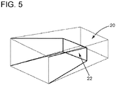
- FIG. 5 shows a theoretical pocket 20, i.e., a desired volume to be removed from the workpiece, and the real pocket 22 that is removed by the above noted methods due to the wear of the electrode or other factors.
- a theoretical pocket 20 i.e., a desired volume to be removed from the workpiece
- the real pocket 22 that is removed by the above noted methods due to the wear of the electrode or other factors.
- a pocket is a volume of material to be removed in one pass of the tool.
- One existing method is to move the working electrode from the blade to a fixed location (i.e., a probe on the machine) and to measure the length of the electrode at the fixed location. After measuring the length and determining that the electrode is shorter that it is supposed to be, the operator may adjust the length of the electrode and restart the processing of the blade. Although this method may ensure a proper length of the electrode, the time involved for moving the electrode to the fixed location, measuring and adjusting the electrode is considerable, sometimes up to 40% of the cycle time, which is undesirable.
- Another approach is to estimate the length of the remaining electrode based on experience. However, this approach is prone to fail when the geometry of the blade is complicated and/or new.
- Chen et al. discloses that a flat 2D path is selected for each pocket (see Chen's Figure 3 ) and each pocket is compensated with a same amount R as shown in Chen's Figure 6 and explained in paragraphs [0028] to [0036].
- the method of Chen et al. is not appropriate for a 3D impeller (which is shown in Figures 3 and 4 ) for a couple of reasons.
- the complex blades shown in Figures 3 and 4 require pockets that are not necessary plane, which cannot be handled by the exiting methods.
- the existing methods use a same compensation step for all pockets ignoring the change in conditions from pocket to pocket and also the change in other parameters.
- the present invention provides a method for compensating a wear of an electrode as defined in claim 1 and a system for compensating a wear of an electrode as defined in claim 12.
- a method for compensating a wear of an electrode that machines a workpiece includes selecting a current pocket from plural pockets of the workpiece; updating a wear compensation to be applied to the electrode for the current pocket based on a wear compensation of a previous pocket, wherein the previous pocket is adjacent to the current pocket; and applying the updated wear compensation to the electrode for machining the current pocket.
- a system for compensating a wear of an electrode that machines a workpiece includes a spindle configured to rotate around an axis and to receive an electrode; a processor configured to control a movement of the spindle and also configured to select a current pocket from plural pockets of the workpiece, update a wear compensation to be applied to the electrode for the current pocket based on a wear compensation of a previous pocket, wherein the previous pocket is adjacent to the current pocket, and apply the updated wear compensation to the electrode for machining the current pocket.
- a computer readable medium including computer executable instruct ions, wherein the instructions, when executed, implement a method for compensating a wear of an electrode that machines a workpiece, the method including providing a system comprising distinct software modules, wherein the distinct software modules comprise an updating wear compensation module; selecting a current pocket from plural pockets of the workpiece; updating a wear compensation to be applied to the electrode for the current pocket based on a wear compensation of a previous pocket, wherein the previous pocket is adjacent to the current pocket; and applying the updated wear compensation to the electrode for machining the current pocket.
- Electrochemical discharge machining is an advanced hybrid machining process including the techniques of ECM and EDM. The process is capable of removing a variety of conductive materials, especially super alloys.
- such an ECDM system 30 includes a machine 32 that is configured to rotate a spindle 34 that holds an electrode 36.
- a link 38 between machine 32 and spindle 34 may include any known mechanism in the art as long as the link 38 and/or machine 32 allows electrode 36 to move along three different axes and to rotate about two different axes.
- the spindle is configured to move along only one axis, two axes, and so on.
- the electrode 36 may be moved towards workpiece 38 for producing the desired shape.
- Workpiece 38 may be supported by a table 40.
- Table 40 may be configured to rotate or displace the workpiece.
- An insulation interface 42 may be provided between workpiece 38 and table 40 for absorbing vibrations of the workpiece 38.
- Another insulation interface 44 may be provided between spindle 34 and link 38.
- Machine 32 may be controlled by a numerical controller 46 for directing electrode 36 along a desired path.
- a power source 48 provides the necessary electrical power to the numerical controller 46, spindle 34 and machine 32.
- Other components that are known in the art may be present, as for example, a device for flushing the removed material, a high pressure pump, a ventilator, suction system, a cell, an electrolyte, another electrode, etc.
- Electrode 36 is able to move not only on X, Y, and Z directions, but also to rotate along two different axes (for example X and Y) by angles theta and phi, respectively.
- electrode 36 is able to provide up to five- axial movement, which makes this machine appropriate for making detailed and complicated geometries in the workpiece for forming the blades of the turbomachines.
- Power source 48 provides enough power so that discharges at the tip of the electrode 36 occur. When a voltage is applied to the electrode 36, discharges occur at the tip of the electrode. Machining takes place on the workpiece 38 surface kept near the electrode 36 tip where discharges occur.
- a pocket (amount of metal to be removed from the workpiece during a pass of the machine) has been defined in the ECM and EDM methods as being a small plane which is removed by the tip of the machine in one pass, in the case of ECDM the pocket may be a single line, a small plane, or other 3D shapes that may be selected by the operator of the machine depending on the geometry of the desired blade.
- FIG. 7 An example of a 3D pocket 70 is shown in Figure 7 in which an actual start point 72 for removing pocket 70 is shown as being at a certain distance from a theoretical start point 74, which is the desired starting point.
- the electrode 36 tip starts removing material from pocket 70 instead of the desired pocket 76, which is called the theoretical pocket as this pocket is envisioned to be removed by the programmer of the machine.
- pocket 70 is removed instead of pocket 76.
- the pocket may be defined to be a single line or a 3D surface, i.e., not only a 2D plane.
- a tool wear compensation process 80 may be implemented as two modules, an off-line module and an online module.
- Figure 8 shows the off- line module 82, which corresponds to a rough compensation, and the online module 84, which corresponds to a fine compensation.
- the off- line module 82 may include a tool path generating module 86 in which software (for example CAD/CAM) generates a tool path (theoretical tool path) for a desired blade design.
- the tool path provides the coordinates to be followed by the machine tool for removing material from the workpiece for forming a desired final product, e.g., a blade.
- the tool path may include information related to the final shape of the blade, the number of pockets to be used for achieving the blade, the exact posit ions of the electrode and/or tool that would manufacture the blade, etc.
- the tool path information is then transmitted via an appropriate interface 88 to a processing element 90 for applying a post process, e.g., translating an output of the generate tool- path 86 to machine language.
- a processing element 90 for applying a post process, e.g., translating an output of the generate tool- path 86 to machine language. It is noted that the tool path calculated by element 86 does not include a compensation for the wear of the electrode, i.e., it is calculated for an ideal electrode that does not undergo any wear.
- a tool wear model module 92 starts from various information for determining the tool wear distribution along the tool path generated by module 86. This information is applied to the tool path determined by module 86 and the real tool path is calculated at this stage. The compensated (real) tool path is provided in step 94 to the on-line module 84.
- tool 30 may have only the off-line module 82 or both the off-line module 82 and the online module 84.
- the online module 84 may be implemented in a corresponding circuit or in a same circuit as the off-line module 82.
- the online module 84 sends to a numerically controlled (NC) system 96 the compensated tool path and the NC system 96 applies the tool path to the machine tool 30.
- the machine tool 30 implements the tool path received from the NC system 96 and removes pocket after pocket.
- an online detection system 98 may be used to determine the length of the electrode of the machine tool 30.
- the NC system 96 may further adjust the tool path or the position of the spindle 34 of the machine tool 30 to compensate for the wear of the electrode. It is noted that by adjusting the position of the spindle 34 instead of recalculating the tool path, the software used for obtaining the blade may be easily distributed to different machines having different geometries, i.e., the software is portable.
- the online detection system 98 may include, for example, a laser calibration system for determining the length of the electrode or a physical contact calibration system, or may include other devices as would be recognized by those skilled in the art. In one application, not only the length of the electrode is determined but also a diameter of the electrode.
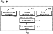
- Figure 9 shows possible modules that are included for determining tool compensating data. More specifically, Figure 9 shows that the tool wear model module 92 includes a material removal calculation module 110, a process parameters sets module 112, and another parameters module 120.
- the material removal calculation module 110 may include between 5 and 15 parameters, for example, electrode shape, electrode material, workpiece material, pocket shape, which are either stored in a memory of the module or actively determined/measured by the system in order to calculate a volume of the material removed from the workpiece by the machine tool.
- the process parameter sets module 112 stores parameters related to the machine tool, e.g., depth of cut, cutting speed, rounds per minute, etc. and the other parameters module 114 stores parameters related to other aspects of the machining process, e.g., flushing flow and pressure, voltage and amperage, current waveform, pulse, etc.
- a transfer function module 116 calculates a tool wear D along a certain axis, for example, a Z axis.
- One or more of the parameters available from modules 112 and 114 may be used in the transfer function.
- the result D of the transfer function f calculated by module 116 is provided to a tool compensation data module 118, which may provide the information directly to the NC 96 for applying the results of the transfer function to the tool path.
- the result of the transfer function may be distributed averagely along the tool path.
- a different wear compensation is applied for each pocket, as will be discussed later.
- the wear compensation of the electrode is calculated/updated for each pocket as the tool machine processes a blade or other element.
- a method for calculating/updating the wear compensation for a current pocket may take into consideration (i) the wear compensation applied to a previous pocket or pockets, and/or (ii) measured/determined parameters of the electrode prior to machining the current pocket.
- the measured/determined parameters include but are not limited to a geometry of the electrode (i.e., length, diameter, etc.).
- the process starts applying a predetermined wear compensation to a first pocket.
- the predetermined wear is generated by the tool wear model.
- This predetermined wear compensation may be an amount determined based on experience.
- the above mentioned parameters may be measured/determined while removing the first pocket and/or at the end of the first pocket and a new (actual) wear compensation is evaluated at the end of the first pocket to be applied to a next pocket.
- the condition in each pocket may be different due to a flushing condition for that pocket, a geometry of the pocket, a geometry of the electrode, tool wear, and other.
- the on- line detect ion system 84 is used to update the conditions of the process and reapply the new wear compensation to the next pocket.
- the calculation of the wear compensation for each current pocket takes into consideration only parameters related to the previous pocket.
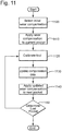
- step 1100 based on data received from the off- line module 82, a wear compensation is selected for a current pocket, which may be a first pocket.
- the machine tool selects the wear compensation based on data stored in the memory of the machine.
- This data may include, among others, material parameters (parameters characterizing the material to be removed to form the blades), electrode parameters as size, chemical composition, etc., electric parameters of the material to be removed, the electrode, and the electrolyte, a 3D geometry of the blade, etc.
- This data is provided to the transfer function as input and the transfer function module 116 determines the wear compensation to be applied to the current pocket in step 1110.
- the electrode of the machine tool is calibrated in step 1120. This calibration may be performed online, off- line or may not be performed at all. Data from the current pocket is collected and provided to the transfer function module 116 to calculate/update in step 1130 the wear compensation for the next pocket.
- the length of the electrode at the beginning of the previous pocket is compared to the length of the electrode at the end of the previous pocket to determine a volume of consumed material from the electrode.
- the machine may calculate the tool path length for the previous pocket and then it may evaluate the tool wear compensation to be applied to the current pocket by dividing the consumed material (e.g., millimeters of graphite) of the electrode with the real length of the tool path in the previous pocket.
- the machine does not use a constant rate of wear of the electrode for all the pockets, which may be available from the manufacturer of the electrode but rather calculates for each current pocket the amount of wear compensation.
- the machine 32 is configured to continuously monitor the ambient and reflect any change in the manufacturing of the next pocket by adjusting the wear compensation of the next pocket.
- the present exemplary embodiment advantageously calculates the wear rate of the same electrode pocket after pocket, consequently applying a different wear compensation to the same electrode pocket after pocket assuming that one or more parameters (e.g., temperature) of the process are changing.
- Other data may be provided to the transfer function module 116 for calculating/updating the wear compensation of the next pocket, as for example, pressure of the ambient, etc.
- the machine may be configured to reduce a size of the next pocket such that the difference between the wear compensation between two successive pockets is maintained below the threshold value.
- the threshold value depends on the machine used, the electrode, the material to be removed from the workpiece, etc.
- step 1140 the wear compensation data calculated/determined in step 1130.
- step 1150 the machine determines in step 1150 whether other pockets have to be processed. If the result is negative, the process ends. If the result is positive, the process advances to step 1120 to process the next pocket and data from the previous pocket is applied to the current pocket for updating the wear compensation as discussed above until all the pockets are processed.
- each pocket may have a different wear compensation so that changing characteristics of the material and/or the environment are taken into consideration. Also, the gap between the real tool path and the theoretical tool path is reduced as the process progresses.
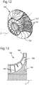
- Still another advantage of one or more embodiments is the possibility to produce complicated structures as shown, for example, in Figures 12 and 13.
- Figure 12 shows an impeller 150 having a shroud 160 and a root 162 that sandwich blades 164.
- Figure 13 is a cross-sectional view of the impeller 150 of Figure 12 and shows cavities 166 that are formed between the blades 164. It is noted that a conventional 3 axis machine tool cannot remove the material for forming cavities 166 as shown in Figure 13 .
- Another advantage of the method described above is that under changing conditions in which the machine operates, the process changes accordingly and adapts to the new conditions by providing an adaptable wear compensation.
- One example is the reductions in size of the pockets to quickly adapt to the actual environmental conditions.
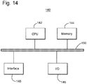
- Circuitry 140 may be part of machine 32 or part of NC system 46 or may be distributed at both of them.
- the circuitry 140 may include a processor 142, memory 144, input/output interface 146, and/or an interface 148 for connecting to, for example, a network. All these elements may be connected to a bus 150.
- Circuitry 140 may be provided on the machine tool and may be linked to various sensors, e.g., pressure, temperature, etc. for measuring corresponding parameters. According to an exemplary embodiment, illustrated in Figure 15 , there is a method for compensating a wear of an electrode that machines a workpiece.
- the method includes a step 1500 of selecting a current pocket from plural pockets of the workpiece, a step 1510 of updating a wear compensation to be applied to the electrode for the current pocket based on wear compensation of a previous pocket and/or other data, wherein the previous pocket is adjacent to the current pocket, and a step 1520 of applying the updated wear compensation to the electrode for machining the current pocket.
- a system for compensating a wear of an electrode that machines a workpiece may include a spindle configured to rotate around an axis and to receive an electrode and a processor.
- the processor is configured to control a movement of the spindle and is also configured to select a current pocket from plural pockets of the workpiece, update a wear compensation to be applied to the electrode for the current pocket based on a wear compensation of a previous pocket, wherein the previous pocket is adjacent to the current pocket, and apply the updated wear compensation to the electrode for machining the current pocket.
- the processor may also be configured to determine a length of a tool path of the electrode for machining the previous pocket, determine an amount of material consumed from the electrode after machining the previous pocket, and divide the amount of material consumed after machining the previous pocket with the length of the tool path for machining the previous pocket for determining the updated wear compensation for the current pocket. Further, the processor may be configured to adjust a size of the current pocket when the updated wear compensation is larger than a predetermined threshold, or to apply a different wear compensation to a first pocket from a second adjacent pocket depending on various parameters of the process, or to apply a predetermined wear compensation to the first pocket of the plural pockets.
- the system may include a memory configured to store parameters on which the predetermined wear compensation is based.
- the spindle of the system may be configured to move about from one to fixe axes such that the electrode carves blades of an impeller from a single piece of metal, or to move the electrode along three axes, and to rotate the electrode about two axes to obtain a five axial machine.
- the processor may be configured to continuously update each pocket of the plural pockets. The updated wear compensation takes into account one or more of an ambient temperature, a flushing pressure, or an amount of current applied to the electrode.
- the disclosed exemplary embodiments provide a system and a method for determining a wear compensation of an electrode that machines a workpiece. It should be understood that this description is not intended to limit the invent ion. On the contrary, the exemplary embodiments are intended to cover alternatives, modifications and equivalents, which are included in the spirit and scope of the invention as defined by the appended claims. Further, in the detailed descript ion of the exemplary embodiments, numerous specific details are set forth in order to provide a comprehensive understanding of the claimed invention. However, one skilled in the art would understand that various embodiments may be practiced without such specific details.
Description
- Embodiments of the subject matter disclosed herein generally relate to methods and systems and, more particularly, to mechanisms and techniques for compensating a path of a tool used to manufacture a workpiece.
- Modern centrifugal compressors include multiple stages of impellers mounted axially along a supporting rotor. The centrifugal compressor stage (impeller) may include many blades. The blades in each stage or row are identical to each other, and typically vary in size and shape from stage to stage.
Figure 1 shows a two-dimensional (2D)impeller 10 of a compressor, theimpeller having blades 12.Figure 2 shows another two-dimensional impeller 10 havingblades 12 covered by acover 13.Figures 3 and 4 shows three-dimensional (3D)impellers 14 havingblades 16. The impeller inFigure 4 has ashroud 18 covering the blades. The shape of the blades determines whether the impeller is 2D or 3D. - In this regard, it is noted that for a 2D impeller as shown in
Figures 1 and 2 , the machining tool that forms the blades needs to move only up and down (along a Z direct ion) relative to the blades and also in a plane (XY plane) perpendicular to the Z direction in order to be able to form the blades. This type of movement is called 3 axial machining. - However, for a more complex design as the 3D impeller shown in
Figures 3 and 4 , the machining tool needs to move in more directions, as will be discussed later. This is the case as theshroud 18 is not attached to theimpeller 14 but is rather an integral part of it. In other words, theimpeller 14,blades 16 andshroud 18 are initially part of a single large piece of metal. Using various techniques, parts of the single piece of metal are slowly removed to form the blades and the shroud. - Various manufacturing processes are available for manufacturing the impeller and turbine blades, yet nevertheless the multitude of such blades requires a substantial expenditure of resources and time, which affect the rate of production and cost of the final machine. One such method is Electric Discharge Machining (EDM). EDM is a manufacturing process whereby a wanted shape of an object, called workpiece, is obtained using electrical discharges (sparks). The material removal from the workpiece occurs by a series of rapidly recurring current discharges between two electrodes, separated by a dielectric liquid and subject to an electric voltage. One of the electrodes is called tool-electrode and is sometimes simply referred to as 'tool' or 'electrode', whereas the other is called workpiece- electrode, commonly abbreviated in 'workpiece'. The tool-electrode is moved by the machine around the workpiece, based on the three-axial movement.
EP 0 406 918 A2 discloses EDM of a workpiece. After machining a feature it is measured to obtain a value which represents its size. - When the distance between the two electrodes is reduced, the intensity of the electric field in the volume between the electrodes is expected to become larger than the strength of the dielectric (at least in some point(s)) and therefore the dielectric breaks allowing some current to flow between the two electrodes. This phenomenon is the same as the breakdown of a capacitor (condenser). A collateral effect of this passage of current is that material is removed from both the electrodes.
- Once the current flow stops, new liquid dielectric should be conveyed into the inter-electrode volume enabling the removed electrode material solid particles (debris) to be carried away and the insulating proprieties of the dielectric to be restored. This addition of new liquid dielectric in the inter- electrode volume is commonly referred to as flushing. Also, after a current flow, a difference of potential between the two electrodes is restored as it was before the breakdown, so that a new liquid dielectric breakdown can occur.
- A second method is Electro Chemical Machining (ECM), which is a method of removing metal by an electrochemical process. ECM is normally used for mass production and is used for working hard materials or materials t hat are difficult to machine using conventional methods. Its use is limited to electrically conductive materials; however, this includes all metals. ECM can cut small, intricate contours or cavities in extremely hard steel and exotic metals such as titanium, hastelloy, kovar, inconel and carbide.
- ECM passes a high current between an electrode and the workpiece, through an electrolyte material removal process having a negatively charged electrode (cathode), a conductive fluid (electrolyte), and a conductive workpiece (anode). The ECM cutting tool is guided along the desired path very close to the work but it does not touch the piece. Unlike EDM however, no sparks are created. High metal removal rates are possible with ECM, along with no thermal or mechanical stresses being transferred to the part, and mirror surface finishes are possible.
- The process schematic is such that a cathode (tool) is advanced into an anode (workpiece). The pressurized electrolyte is injected at a set temperature to the area being cut. The feed rate is the exact same rate as the rate of liquefaction of the material. The area in between the tool and the workpiece varies within 0.003 in (0.076 mm) and 0.030 in (0.76 mm).
The EDM and ECM are traditionally used for making the blades in the turbines and compressors. The blades are formed by removing excessive material from an original workpiece, which is a solid piece of metal having no blades. The EDM or ECM electrode carves the desired blades in the solid piece of metal for forming the blades. These blades are typically solid because they are made of a superalloy metal, to resist to the extreme conditions inside the turbine or compressor. However, a limitation that affects one or both EDM and ECM methods is the wear of the electrode used for removing the excessive material. As discussed above, while a current is applied between the electrode of the tool and the workpiece that is desired to be machined, the electric discharge removes material not only from the workpiece but also from the electrode of the tool. Thus, as the electrode is removing more and more material from the workpiece to create the blade, a length of the electrode becomes shorter. The shorter electrode would not be able to remove the desired amount of material from the workpiece for creating the blades. - This shortcoming of the EDM and ECM methods is illustrated by
Figure 5 , which shows atheoretical pocket 20, i.e., a desired volume to be removed from the workpiece, and thereal pocket 22 that is removed by the above noted methods due to the wear of the electrode or other factors. For forming a single blade, a few pockets around the blade have to be removed. A pocket is a volume of material to be removed in one pass of the tool. - However, for obtaining an accurate blade, it is necessary to compensate the reduction in size of the electrode. One existing method is to move the working electrode from the blade to a fixed location (i.e., a probe on the machine) and to measure the length of the electrode at the fixed location. After measuring the length and determining that the electrode is shorter that it is supposed to be, the operator may adjust the length of the electrode and restart the processing of the blade. Although this method may ensure a proper length of the electrode, the time involved for moving the electrode to the fixed location, measuring and adjusting the electrode is considerable, sometimes up to 40% of the cycle time, which is undesirable. Another approach is to estimate the length of the remaining electrode based on experience. However, this approach is prone to fail when the geometry of the blade is complicated and/or new.
- Another approach is described in
Chen et al., U.S. Patent Application Publication No. 2006/0138092 . Chen et al. discloses that a flat 2D path is selected for each pocket (see Chen'sFigure 3 ) and each pocket is compensated with a same amount R as shown in Chen'sFigure 6 and explained in paragraphs [0028] to [0036]. However, the method of Chen et al. is not appropriate for a 3D impeller (which is shown inFigures 3 and 4 ) for a couple of reasons. - First, the above discussed methods are limited by the 3 axial movement of the electrode and blades having complicated geometries as shown in
Figures 3 and 4 cannot be achieved with this kind of movement. - Second, the complex blades shown in
Figures 3 and 4 require pockets that are not necessary plane, which cannot be handled by the exiting methods. Third, the existing methods use a same compensation step for all pockets ignoring the change in conditions from pocket to pocket and also the change in other parameters. - Accordingly, it would be desirable to provide systems and methods that avoid the afore- described problems and drawbacks as well as others understood by those skilled in the art after consideration of the subject matter disclosed below.
- The present invention provides a method for compensating a wear of an electrode as defined in
claim 1 and a system for compensating a wear of an electrode as defined inclaim 12. - According to one exemplary embodiment, there is a method for compensating a wear of an electrode that machines a workpiece. The method includes selecting a current pocket from plural pockets of the workpiece; updating a wear compensation to be applied to the electrode for the current pocket based on a wear compensation of a previous pocket, wherein the previous pocket is adjacent to the current pocket; and applying the updated wear compensation to the electrode for machining the current pocket.
- According to another exemplary embodiment, there is a system for compensating a wear of an electrode that machines a workpiece. The system includes a spindle configured to rotate around an axis and to receive an electrode; a processor configured to control a movement of the spindle and also configured to select a current pocket from plural pockets of the workpiece, update a wear compensation to be applied to the electrode for the current pocket based on a wear compensation of a previous pocket, wherein the previous pocket is adjacent to the current pocket, and apply the updated wear compensation to the electrode for machining the current pocket.
- According to still another exemplary embodiment, there is a computer readable medium including computer executable instruct ions, wherein the instructions, when executed, implement a method for compensating a wear of an electrode that machines a workpiece, the method including providing a system comprising distinct software modules, wherein the distinct software modules comprise an updating wear compensation module; selecting a current pocket from plural pockets of the workpiece; updating a wear compensation to be applied to the electrode for the current pocket based on a wear compensation of a previous pocket, wherein the previous pocket is adjacent to the current pocket; and applying the updated wear compensation to the electrode for machining the current pocket.
- The accompanying drawings, which are incorporated in and constitute a part of the specification, illustrate one or more embodiments and, together with the description, explain these embodiments. In the drawings:
-
Figure 1 is a schematic diagram of an open impeller having 2D blades; -
Figure 2 is a schematic diagram of a closed impeller having 2D blades; -
Figure 3 is a schematic diagram of an open impeller having 3D blades; -
Figure 4 is a schematic diagram of a closed impeller having 3D blades; -
Figure 5 is a schematic diagram illustrating a gap between a real pocket and an ideal pocket; -
Figure 6 is a schematic diagram of a machine tool according to an exemplary embodiment; -
Figure 7 is a schematic diagram illustrating material removal with an electrode; -
Figure 8 is a schematic diagram of a module for determining wear compensation of the electrode according to an exemplary embodiment; -
Figure 9 is a schematic diagram of a tool wear model module according to an exemplary embodiment; -
Figure 10 is a schematic diagram of a decreasing gap between a real tool path and an ideal tool path according to an exemplary embodiment; -
Figure 11 is a flow chart illustrating steps performed by the machine tool for removing material from a workpiece according to an exemplary embodiment; -
Figure 12 is a schematic diagram of a closed impeller having a 3D geometry; -
Figure 13 is a cross section of the closed impeller ofFigure 12 ; -
Figure 14 is a schematic diagram of circuitry that determine a control path and control the machine tool according to an exemplary embodiment; and -
Figure 15 is a flow chart illustrating steps performed by the machine tool according to an exemplary embodiment. - The following description of the exemplary embodiments refers to the accompanying drawings. The same reference numbers in different drawings identify the same or similar elements. The following detailed description does not limit the invention. Instead, the scope of the invention is defined by the appended claims. The following embodiments are discussed, for simplicity, with regard to the terminology and structure of turbine blades. However, the embodiments to be discussed next are not limited to these systems, but may be applied to other systems that require the removal of material at various angles and positions for forming a desired shape with a desired size.
- Reference throughout the specification to "one embodiment" or "an embodiment" means that a particular feature, structure, or characteristic described in connection with an embodiment is included in at least one embodiment of the subject matter disclosed. Thus, the appearance of the phrases "in one embodiment" or "in an embodiment" in various places throughout the specification is not necessarily referring to the same embodiment. Further, the particular features, structures or characteristics may be combined in any suitable manner in one or more embodiments.
- Electrochemical discharge machining (ECDM) is an advanced hybrid machining process including the techniques of ECM and EDM. The process is capable of removing a variety of conductive materials, especially super alloys.
- Two examples of ECDM are found in
U.S. Pat. Nos. 6,562,227 and6,787,728 , which are incorporated herein by reference. As shown inFigure 6 , such anECDM system 30 includes amachine 32 that is configured to rotate aspindle 34 that holds anelectrode 36. Alink 38 betweenmachine 32 andspindle 34 may include any known mechanism in the art as long as thelink 38 and/ormachine 32 allowselectrode 36 to move along three different axes and to rotate about two different axes. In one application, the spindle is configured to move along only one axis, two axes, and so on. Theelectrode 36 may be moved towardsworkpiece 38 for producing the desired shape.Workpiece 38 may be supported by a table 40. Table 40 may be configured to rotate or displace the workpiece. Aninsulation interface 42 may be provided betweenworkpiece 38 and table 40 for absorbing vibrations of theworkpiece 38. Anotherinsulation interface 44 may be provided betweenspindle 34 andlink 38.Machine 32 may be controlled by anumerical controller 46 for directingelectrode 36 along a desired path. Apower source 48 provides the necessary electrical power to thenumerical controller 46,spindle 34 andmachine 32. Other components that are known in the art may be present, as for example, a device for flushing the removed material, a high pressure pump, a ventilator, suction system, a cell, an electrolyte, another electrode, etc.Electrode 36 is able to move not only on X, Y, and Z directions, but also to rotate along two different axes (for example X and Y) by angles theta and phi, respectively. - In this way,
electrode 36 is able to provide up to five- axial movement, which makes this machine appropriate for making detailed and complicated geometries in the workpiece for forming the blades of theturbomachines. Power source 48 provides enough power so that discharges at the tip of theelectrode 36 occur. When a voltage is applied to theelectrode 36, discharges occur at the tip of the electrode. Machining takes place on theworkpiece 38 surface kept near theelectrode 36 tip where discharges occur. While a pocket (amount of metal to be removed from the workpiece during a pass of the machine) has been defined in the ECM and EDM methods as being a small plane which is removed by the tip of the machine in one pass, in the case of ECDM the pocket may be a single line, a small plane, or other 3D shapes that may be selected by the operator of the machine depending on the geometry of the desired blade. - An example of a
3D pocket 70 is shown inFigure 7 in which anactual start point 72 for removingpocket 70 is shown as being at a certain distance from atheoretical start point 74, which is the desired starting point. Thus, theelectrode 36 tip starts removing material frompocket 70 instead of the desiredpocket 76, which is called the theoretical pocket as this pocket is envisioned to be removed by the programmer of the machine. However, because of the uncompensated tool wear,pocket 70 is removed instead ofpocket 76. According to an exemplary embodiment, the pocket may be defined to be a single line or a 3D surface, i.e., not only a 2D plane. - According to an exemplary embodiment, a tool
wear compensation process 80 may be implemented as two modules, an off-line module and an online module.Figure 8 shows the off-line module 82, which corresponds to a rough compensation, and theonline module 84, which corresponds to a fine compensation. The off-line module 82 may include a toolpath generating module 86 in which software (for example CAD/CAM) generates a tool path (theoretical tool path) for a desired blade design. The tool path provides the coordinates to be followed by the machine tool for removing material from the workpiece for forming a desired final product, e.g., a blade. The tool path may include information related to the final shape of the blade, the number of pockets to be used for achieving the blade, the exact posit ions of the electrode and/or tool that would manufacture the blade, etc. The tool path information is then transmitted via anappropriate interface 88 to aprocessing element 90 for applying a post process, e.g., translating an output of the generate tool-path 86 to machine language. It is noted that the tool path calculated byelement 86 does not include a compensation for the wear of the electrode, i.e., it is calculated for an ideal electrode that does not undergo any wear. - Based on a tool wear model to be discussed later, a tool
wear model module 92 starts from various information for determining the tool wear distribution along the tool path generated bymodule 86. This information is applied to the tool path determined bymodule 86 and the real tool path is calculated at this stage. The compensated (real) tool path is provided instep 94 to the on-line module 84. However, according to an exemplary embodiment,tool 30 may have only the off-line module 82 or both the off-line module 82 and theonline module 84. - According to an exemplary embodiment, the
online module 84 may be implemented in a corresponding circuit or in a same circuit as the off-line module 82. Theonline module 84 sends to a numerically controlled (NC)system 96 the compensated tool path and theNC system 96 applies the tool path to themachine tool 30. Themachine tool 30 implements the tool path received from theNC system 96 and removes pocket after pocket. After finishing a pocket, anonline detection system 98 may be used to determine the length of the electrode of themachine tool 30. Based on the measurement performed by theonline detection system 98, theNC system 96 may further adjust the tool path or the position of thespindle 34 of themachine tool 30 to compensate for the wear of the electrode. It is noted that by adjusting the position of thespindle 34 instead of recalculating the tool path, the software used for obtaining the blade may be easily distributed to different machines having different geometries, i.e., the software is portable. - The
online detection system 98 may include, for example, a laser calibration system for determining the length of the electrode or a physical contact calibration system, or may include other devices as would be recognized by those skilled in the art. In one application, not only the length of the electrode is determined but also a diameter of the electrode. - With regard to the tool
wear model module 92,Figure 9 shows possible modules that are included for determining tool compensating data. More specifically,Figure 9 shows that the toolwear model module 92 includes a materialremoval calculation module 110, a process parameters setsmodule 112, and another parameters module 120. - These modules may be implemented as dedicated circuitry, software or a combination thereof. The material
removal calculation module 110 may include between 5 and 15 parameters, for example, electrode shape, electrode material, workpiece material, pocket shape, which are either stored in a memory of the module or actively determined/measured by the system in order to calculate a volume of the material removed from the workpiece by the machine tool. - The process parameter sets
module 112 stores parameters related to the machine tool, e.g., depth of cut, cutting speed, rounds per minute, etc. and theother parameters module 114 stores parameters related to other aspects of the machining process, e.g., flushing flow and pressure, voltage and amperage, current waveform, pulse, etc. - Based on the parameters and other data received from
modules transfer function module 116 calculates a tool wear D along a certain axis, for example, a Z axis. The tool wear is given by a transfer function f, which may be expressed as D = f(Vmm, P_on, P_off, Ipeak, Pflushing, ...),where Vmm is the volume of removed material, P_on is the fraction of the unit of time in which the current is on, P_off is the fraction of the unit of time in which the current is off, Ipeak is the peak current applied toelectrode 36, Pflushing is the flushing pressure and flow, etc. One or more of the parameters available frommodules module 116 is provided to a toolcompensation data module 118, which may provide the information directly to theNC 96 for applying the results of the transfer function to the tool path. According to an exemplary embodiment, the result of the transfer function may be distributed averagely along the tool path. According to still another exemplary embodiment, a different wear compensation is applied for each pocket, as will be discussed later. - According to another exemplary embodiment, the wear compensation of the electrode is calculated/updated for each pocket as the tool machine processes a blade or other element. A method for calculating/updating the wear compensation for a current pocket may take into consideration (i) the wear compensation applied to a previous pocket or pockets, and/or (ii) measured/determined parameters of the electrode prior to machining the current pocket. The measured/determined parameters include but are not limited to a geometry of the electrode (i.e., length, diameter, etc.).
- According to an exemplary embodiment, the process starts applying a predetermined wear compensation to a first pocket. The predetermined wear is generated by the tool wear model. This predetermined wear compensation may be an amount determined based on experience. The above mentioned parameters (geometry of the electrode) may be measured/determined while removing the first pocket and/or at the end of the first pocket and a new (actual) wear compensation is evaluated at the end of the first pocket to be applied to a next pocket. The condition in each pocket may be different due to a flushing condition for that pocket, a geometry of the pocket, a geometry of the electrode, tool wear, and other. The on- line detect
ion system 84 is used to update the conditions of the process and reapply the new wear compensation to the next pocket. - As a result of this reliance of the wear compensation for a current pocket on previous pocket(s), a gap between the
real path 130 and thetheoretical path 132 improves as the machine tool advances, as shown inFigure 10 . According to an exemplary embodiment, the calculation of the wear compensation for each current pocket takes into consideration only parameters related to the previous pocket. - The steps of a method for calculating/determining the wear compensation for the machine tool as discussed above are exemplified with regard to
Figure 11 . Instep 1100, based on data received from the off-line module 82, a wear compensation is selected for a current pocket, which may be a first pocket. In other words, the machine tool selects the wear compensation based on data stored in the memory of the machine. This data may include, among others, material parameters (parameters characterizing the material to be removed to form the blades), electrode parameters as size, chemical composition, etc., electric parameters of the material to be removed, the electrode, and the electrolyte, a 3D geometry of the blade, etc. - This data is provided to the transfer function as input and the
transfer function module 116 determines the wear compensation to be applied to the current pocket instep 1110. After the current pocket has been removed, the electrode of the machine tool is calibrated instep 1120. This calibration may be performed online, off- line or may not be performed at all. Data from the current pocket is collected and provided to thetransfer function module 116 to calculate/update instep 1130 the wear compensation for the next pocket. - In one application, the length of the electrode at the beginning of the previous pocket is compared to the length of the electrode at the end of the previous pocket to determine a volume of consumed material from the electrode. Also, the machine may calculate the tool path length for the previous pocket and then it may evaluate the tool wear compensation to be applied to the current pocket by dividing the consumed material (e.g., millimeters of graphite) of the electrode with the real length of the tool path in the previous pocket. According to this exemplary embodiment, the machine does not use a constant rate of wear of the electrode for all the pockets, which may be available from the manufacturer of the electrode but rather calculates for each current pocket the amount of wear compensation. In this way, local factors specifics for each machine, e.g., flushing rate, flushing pressure, ambient temperature, etc., which also influence the wear rate of the electrode, are taken into account when calculating the new wear compensation of the electrode. In other words, by calculating for a current pocket the consumed material and the path length, most of the parameters that influence the ECDM process are factored in. The change of one or more of these parameters during the ECDM process is reflected in the material removed during the current pocket. These changes are applied to the next pocket due to the calculations discussed above. Thus, according to an exemplary embodiment, the
machine 32 is configured to continuously monitor the ambient and reflect any change in the manufacturing of the next pocket by adjusting the wear compensation of the next pocket. - For example, while a traditional machine uses a same wear compensation for each pocket as the wear rate of the electrode is constant, the present exemplary embodiment advantageously calculates the wear rate of the same electrode pocket after pocket, consequently applying a different wear compensation to the same electrode pocket after pocket assuming that one or more parameters (e.g., temperature) of the process are changing. Other data may be provided to the
transfer function module 116 for calculating/updating the wear compensation of the next pocket, as for example, pressure of the ambient, etc. In one application, if a wear compensation of a current pocket differs from a wear compensations of a next pocket by more than a certain threshold value, the machine may be configured to reduce a size of the next pocket such that the difference between the wear compensation between two successive pockets is maintained below the threshold value. The threshold value depends on the machine used, the electrode, the material to be removed from the workpiece, etc. - Having the wear compensation data calculated/determined in
step 1130, this data is applied instep 1140 to themachine tool 30 when machining the next pocket. Once the next pocket is finished, the machine determines instep 1150 whether other pockets have to be processed. If the result is negative, the process ends. If the result is positive, the process advances to step 1120 to process the next pocket and data from the previous pocket is applied to the current pocket for updating the wear compensation as discussed above until all the pockets are processed. - One advantage of this method is that each pocket may have a different wear compensation so that changing characteristics of the material and/or the environment are taken into consideration. Also, the gap between the real tool path and the theoretical tool path is reduced as the process progresses.
- Still another advantage of one or more embodiments is the possibility to produce complicated structures as shown, for example, in
Figures 12 and 13. Figure 12 shows animpeller 150 having ashroud 160 and aroot 162 thatsandwich blades 164.Figure 13 is a cross-sectional view of theimpeller 150 ofFigure 12 and showscavities 166 that are formed between theblades 164. It is noted that a conventional 3 axis machine tool cannot remove the material for formingcavities 166 as shown inFigure 13 .
Another advantage of the method described above is that under changing conditions in which the machine operates, the process changes accordingly and adapts to the new conditions by providing an adaptable wear compensation. One example is the reductions in size of the pockets to quickly adapt to the actual environmental conditions. These advantages may not be achieved by the traditional machines as those machines are using fixed wear rates of the electrodes and do not take into consideration the influence of the ambient on the ECDM process. - The various modules shown in the figures may be implemented, for example, in
circuitry 140 as shown inFigure 14 .Circuitry 140 may be part ofmachine 32 or part ofNC system 46 or may be distributed at both of them. Thecircuitry 140 may include aprocessor 142,memory 144, input/output interface 146, and/or aninterface 148 for connecting to, for example, a network. All these elements may be connected to abus 150.Circuitry 140 may be provided on the machine tool and may be linked to various sensors, e.g., pressure, temperature, etc. for measuring corresponding parameters. According to an exemplary embodiment, illustrated inFigure 15 , there is a method for compensating a wear of an electrode that machines a workpiece. The method includes astep 1500 of selecting a current pocket from plural pockets of the workpiece, astep 1510 of updating a wear compensation to be applied to the electrode for the current pocket based on wear compensation of a previous pocket and/or other data, wherein the previous pocket is adjacent to the current pocket, and astep 1520 of applying the updated wear compensation to the electrode for machining the current pocket. - Based on the above discussed method, a system for compensating a wear of an electrode that machines a workpiece may include a spindle configured to rotate around an axis and to receive an electrode and a processor. The processor is configured to control a movement of the spindle and is also configured to select a current pocket from plural pockets of the workpiece, update a wear compensation to be applied to the electrode for the current pocket based on a wear compensation of a previous pocket, wherein the previous pocket is adjacent to the current pocket, and apply the updated wear compensation to the electrode for machining the current pocket.
- The processor may also be configured to determine a length of a tool path of the electrode for machining the previous pocket, determine an amount of material consumed from the electrode after machining the previous pocket, and divide the amount of material consumed after machining the previous pocket with the length of the tool path for machining the previous pocket for determining the updated wear compensation for the current pocket. Further, the processor may be configured to adjust a size of the current pocket when the updated wear compensation is larger than a predetermined threshold, or to apply a different wear compensation to a first pocket from a second adjacent pocket depending on various parameters of the process, or to apply a predetermined wear compensation to the first pocket of the plural pockets. The system may include a memory configured to store parameters on which the predetermined wear compensation is based. The spindle of the system may be configured to move about from one to fixe axes such that the electrode carves blades of an impeller from a single piece of metal, or to move the electrode along three axes, and to rotate the electrode about two axes to obtain a five axial machine. The processor may be configured to continuously update each pocket of the plural pockets. The updated wear compensation takes into account one or more of an ambient temperature, a flushing pressure, or an amount of current applied to the electrode.
- The disclosed exemplary embodiments provide a system and a method for determining a wear compensation of an electrode that machines a workpiece. It should be understood that this description is not intended to limit the invent ion. On the contrary, the exemplary embodiments are intended to cover alternatives, modifications and equivalents, which are included in the spirit and scope of the invention as defined by the appended claims. Further, in the detailed descript ion of the exemplary embodiments, numerous specific details are set forth in order to provide a comprehensive understanding of the claimed invention. However, one skilled in the art would understand that various embodiments may be practiced without such specific details.
- Although the features and elements of the present exemplary embodiments are described in the embodiments in particular combinations, each feature or element can be used alone without the other features and elements of the embodiments or in various combinations with or without other features and elements disclosed herein.
- This written description uses examples to disclose the invention, including the best mode, and also to enable any person skilled in the art to practice the invention, including making and using any devices or systems and performing any incorporated methods.
- The patentable scope of the invention is defined by the claims.
Claims (12)
- A method for machining a workpiece (38) by electrochemical discharge machining (ECDM), electrochemical machining (ECM) or electric discharge machining (EDM), the method comprising:removing the material from the workpiece by sequentially machining a number of pockets,compensating for the wear of the machining electrode by:selecting a current pocket to be machined from plural pockets of the workpiece;updating a wear compensation to be applied to the electrode for the current pocket generated by a tool wear model (92) based on a wear compensation of a previous pocket,wherein the previous pocket is adjacent to the current pocket; andapplying the updated wear compensation to compensate for wear to the geometry of the electrode to the electrode for machining the current pocket.
- The method of Claim 1, wherein the step of updating further comprises:determining a length of a tool path of the electrode for machining the previous pocket;determining an amount of material consumed from the electrode after machining the previous pocket; anddividing the amount of material consumed after machining the previous pocket by the length of the tool path for machining the previous pocket for determining the updated wear compensation for the current pocket.
- The method of Claim 2, further comprising:adjusting a size of the current pocket when the updated wear compensation is larger than a predetermined threshold.
- The method of Claim 1, further comprising:applying a different wear compensation to a first pocket from a second adjacent pocket depending on various parameters of the process.
- The method of Claim 1, further comprising:applying a predetermined wear compensation to the first pocket of the plural pockets.
- The method of Claim 5, wherein the predetermined wear compensation is based on parameters stored in a memory.
- The method of Claim 1, further comprising:carving blades of an impeller from a single piece of metal by moving the electrode about from one to five axes.
- The method of Claim 1, wherein the step of updating further includes:continuously updating each pocket of the plural pockets.
- The method of Claim 1, wherein the updated wear compensation takes into account one or more of an ambient temperature, a flushing pressure, or an amount of current applied to the electrode.
- The method of any preceding claim, wherein updating a wear compensation for the current pocket takes into consideration measured/determined parameters of the electrode prior to machining the current pocket.
- The method of claim 10, wherein the measured/determined parameters include a geometry of the electrode.
- A system for machining a workpiece (38) by electrochemical discharge machining (ECDM), electrochemical machining (ECM) or electric discharge machining (EDM), the system comprising:a spindle (34) configured to rotate around an axis and to receive an electrode (36);a processor configured to control a movement of the spindle (34), to control the machining so that a number of pockets are sequentially machined, and also configured to compensate for the wear of the machining electrode by being configured to select a current pocket to be machined from plural pockets of the workpiece (38), update a wear compensation to be applied to the electrode (36) for the current pocket generated by a tool wear model (92) based on a wear compensation of a previous pocket, wherein the previous pocket is adjacent to the current pocket, and apply the updated wear compensation to compensate for wear to the geometry of the electrode to the electrode (36) for machining the current pocket.
Applications Claiming Priority (2)
| Application Number | Priority Date | Filing Date | Title |
|---|---|---|---|
| ITCO2009A000042A IT1396512B1 (en) | 2009-10-21 | 2009-10-21 | METHOD AND DEVICE FOR TOOL COMPENSATION |
| PCT/US2010/048691 WO2011049686A1 (en) | 2009-10-21 | 2010-09-14 | Tool compensation method and device |
Publications (2)
| Publication Number | Publication Date |
|---|---|
| EP2490851A1 EP2490851A1 (en) | 2012-08-29 |
| EP2490851B1 true EP2490851B1 (en) | 2018-12-19 |
Family
ID=42211883
Family Applications (1)
| Application Number | Title | Priority Date | Filing Date |
|---|---|---|---|
| EP10757520.1A Active EP2490851B1 (en) | 2009-10-21 | 2010-09-14 | Tool compensation method and device |
Country Status (12)
| Country | Link |
|---|---|
| US (1) | US8999136B2 (en) |
| EP (1) | EP2490851B1 (en) |
| JP (1) | JP5771212B2 (en) |
| KR (1) | KR101747465B1 (en) |
| CN (1) | CN102596474B (en) |
| BR (1) | BR112012009405A2 (en) |
| CA (1) | CA2778272C (en) |
| IN (1) | IN2012DN03037A (en) |
| IT (1) | IT1396512B1 (en) |
| MX (1) | MX2012004717A (en) |
| RU (1) | RU2553785C2 (en) |
| WO (1) | WO2011049686A1 (en) |
Families Citing this family (5)
| Publication number | Priority date | Publication date | Assignee | Title |
|---|---|---|---|---|
| RU2017106913A (en) * | 2014-09-17 | 2018-10-18 | Нуово Пиньоне СРЛ | CONTROL OF GEOMETRIC PARAMETERS AND OPTIMAL FITTING OF TOOLS FOR ELECTROEROSION PROCESSING |
| JP6693827B2 (en) * | 2016-07-22 | 2020-05-13 | 株式会社放電精密加工研究所 | Method of manufacturing integrated impeller |
| US10363622B2 (en) | 2016-09-30 | 2019-07-30 | General Electric Company | Electrode for an electro-erosion process and an associated method thereof |
| TW201924832A (en) * | 2017-12-01 | 2019-07-01 | 財團法人金屬工業研究發展中心 | Tool setting device for electrochemical machining and tool setting method thereof capable of automatically detecting the position of the machining electrode and controlling the movement of the machining electrode |
| CN113770463B (en) * | 2021-09-27 | 2022-10-11 | 深圳大学 | Micro stepped hole machining method based on electrode loss |
Citations (8)
| Publication number | Priority date | Publication date | Assignee | Title |
|---|---|---|---|---|
| US2969482A (en) | 1956-10-08 | 1961-01-24 | Centre Nat Rech Scient | Machining systems making use of intermittent electrical discharges |
| GB1293576A (en) | 1968-12-05 | 1972-10-18 | Ingersoll Milling Machine Co | Edm method and apparatus for finishing rolls |
| JPH0230431A (en) | 1988-07-18 | 1990-01-31 | Hoden Seimitsu Kako Kenkyusho Ltd | Power unit for discharge processing |
| EP0406918A2 (en) | 1985-09-27 | 1991-01-09 | Raycon Corporation | Method and apparatus for electric discharge machining |
| GB2357339A (en) | 1999-12-16 | 2001-06-20 | Leamount Ltd | Measuring the depth of a workpiece formation comprising accounting for shortening of the forming tool |
| EP1211009A1 (en) | 2000-11-30 | 2002-06-05 | Nuovo Pignone Holding S.P.A. | Method for production of a rotor for centrifugal compressors |
| EP1808251A1 (en) | 2006-01-16 | 2007-07-18 | Siemens Aktiengesellschaft | Method of dressing an erosion electrode and electroerosive machining method |
| US20080173618A1 (en) | 2007-01-23 | 2008-07-24 | Industrial Technology Research Institute | Method for detecting and compensating electrode wear of electric discharge machining |
Family Cites Families (21)
| Publication number | Priority date | Publication date | Assignee | Title |
|---|---|---|---|---|
| SU833420A2 (en) * | 1979-08-01 | 1981-05-30 | Предприятие П/Я М-5813 | Method of producing tool electrode for electroerosion broaching |
| SU1228986A1 (en) * | 1982-09-17 | 1986-05-07 | Научно-Исследовательский Институт Тяжелого Машиностроения Производственного Объединения "Уралмаш" | Method of electric resistance working |
| EP0555818B1 (en) * | 1992-02-12 | 1995-12-13 | Charmilles Technologies S.A. | Method and apparatus for electric discharge machining a hollow three dimensional contour using a thin, rotating electrode |
| JP2983436B2 (en) | 1994-07-21 | 1999-11-29 | 三菱電機株式会社 | Electric discharge machine |
| JP3395431B2 (en) * | 1995-02-27 | 2003-04-14 | 三菱電機株式会社 | Electric discharge machining method and apparatus |
| JPH0957579A (en) * | 1995-08-22 | 1997-03-04 | Toshiba Mach Co Ltd | Dynamic tool abrasion correction method in nc machine tool |
| US5851104A (en) | 1997-12-15 | 1998-12-22 | Atlas Copco Rotoflow, Inc. | Nozzle adjusting mechanism |
| DE60133989D1 (en) * | 2001-03-05 | 2008-06-26 | Charmilles Technologies | Method and device for machining a three-dimensional workpiece by means of EDM milling |
| TW520311B (en) * | 2001-04-12 | 2003-02-11 | Castek Mechatron Industry Co L | Method of automatic electrode wear compensation in equal depth pore electro-discharge machining |
| US6562227B2 (en) | 2001-07-31 | 2003-05-13 | General Electric Company | Plunge electromachining |
| JP2004142027A (en) | 2002-10-24 | 2004-05-20 | Fanuc Ltd | Wire electric discharge machine |
| US6858125B2 (en) * | 2002-12-27 | 2005-02-22 | General Electric Company | Multi-axis numerical control electromachining of bladed disks |
| US6787728B2 (en) | 2002-12-27 | 2004-09-07 | General Electric Company | Method and apparatus for near net shape rapid rough electromachining for blisks |
| JP2004351571A (en) | 2003-05-29 | 2004-12-16 | Fanuc Ltd | Method for adjusting nozzle gap |
| ITMI20032608A1 (en) | 2003-12-29 | 2005-06-30 | Nuovo Pignone Spa | CENTRIFUGAL COMPRESSOR PALETTE SYSTEM WITH REGULATION MECHANISM |
| US20050247569A1 (en) | 2004-05-07 | 2005-11-10 | Lamphere Michael S | Distributed arc electroerosion |
| SE528770C2 (en) * | 2004-08-25 | 2007-02-13 | Seco Tools Ab | Cutting tool for sharpening electrode tips with interchangeable inserts |
| TWI277846B (en) * | 2004-12-23 | 2007-04-01 | Ind Tech Res Inst | Method of 3D electric discharge machining and program generating apparatus therefor |
| ITMI20051518A1 (en) | 2005-08-02 | 2007-02-03 | Nuovo Pignone Spa | SYSTEM FOR ELECTROEROSION FOR THE CONSTRUCTION OF A HOLLOW OR I A SHAPED HOLE IN A PARTICULAR |
| US7824526B2 (en) | 2006-12-11 | 2010-11-02 | General Electric Company | Adaptive spindle assembly for electroerosion machining on a CNC machine tool |
| US8236162B2 (en) * | 2008-09-30 | 2012-08-07 | General Electric Company | Electroerosion machining system and method for electrode wear compensation |
-
2009
- 2009-10-21 IT ITCO2009A000042A patent/IT1396512B1/en active
-
2010
- 2010-09-14 MX MX2012004717A patent/MX2012004717A/en active IP Right Grant
- 2010-09-14 KR KR1020127010123A patent/KR101747465B1/en active IP Right Grant
- 2010-09-14 RU RU2012115682/02A patent/RU2553785C2/en not_active IP Right Cessation
- 2010-09-14 CA CA2778272A patent/CA2778272C/en not_active Expired - Fee Related
- 2010-09-14 IN IN3037DEN2012 patent/IN2012DN03037A/en unknown
- 2010-09-14 JP JP2012535208A patent/JP5771212B2/en active Active
- 2010-09-14 WO PCT/US2010/048691 patent/WO2011049686A1/en active Application Filing
- 2010-09-14 EP EP10757520.1A patent/EP2490851B1/en active Active
- 2010-09-14 BR BR112012009405-0A patent/BR112012009405A2/en not_active Application Discontinuation
- 2010-09-14 US US13/503,290 patent/US8999136B2/en active Active
- 2010-09-14 CN CN201080049059.XA patent/CN102596474B/en active Active
Patent Citations (8)
| Publication number | Priority date | Publication date | Assignee | Title |
|---|---|---|---|---|
| US2969482A (en) | 1956-10-08 | 1961-01-24 | Centre Nat Rech Scient | Machining systems making use of intermittent electrical discharges |
| GB1293576A (en) | 1968-12-05 | 1972-10-18 | Ingersoll Milling Machine Co | Edm method and apparatus for finishing rolls |
| EP0406918A2 (en) | 1985-09-27 | 1991-01-09 | Raycon Corporation | Method and apparatus for electric discharge machining |
| JPH0230431A (en) | 1988-07-18 | 1990-01-31 | Hoden Seimitsu Kako Kenkyusho Ltd | Power unit for discharge processing |
| GB2357339A (en) | 1999-12-16 | 2001-06-20 | Leamount Ltd | Measuring the depth of a workpiece formation comprising accounting for shortening of the forming tool |
| EP1211009A1 (en) | 2000-11-30 | 2002-06-05 | Nuovo Pignone Holding S.P.A. | Method for production of a rotor for centrifugal compressors |
| EP1808251A1 (en) | 2006-01-16 | 2007-07-18 | Siemens Aktiengesellschaft | Method of dressing an erosion electrode and electroerosive machining method |
| US20080173618A1 (en) | 2007-01-23 | 2008-07-24 | Industrial Technology Research Institute | Method for detecting and compensating electrode wear of electric discharge machining |
Also Published As
| Publication number | Publication date |
|---|---|
| US8999136B2 (en) | 2015-04-07 |
| CN102596474B (en) | 2015-09-30 |
| EP2490851A1 (en) | 2012-08-29 |
| ITCO20090042A1 (en) | 2011-04-22 |
| US20120240386A1 (en) | 2012-09-27 |
| RU2553785C2 (en) | 2015-06-20 |
| CA2778272A1 (en) | 2011-04-28 |
| MX2012004717A (en) | 2012-06-28 |
| RU2012115682A (en) | 2013-11-27 |
| IN2012DN03037A (en) | 2015-07-31 |
| JP5771212B2 (en) | 2015-08-26 |
| CN102596474A (en) | 2012-07-18 |
| JP2013508179A (en) | 2013-03-07 |
| BR112012009405A2 (en) | 2020-09-01 |
| CA2778272C (en) | 2018-10-30 |
| IT1396512B1 (en) | 2012-12-14 |
| KR20120091096A (en) | 2012-08-17 |
| WO2011049686A1 (en) | 2011-04-28 |
| KR101747465B1 (en) | 2017-06-14 |
Similar Documents
| Publication | Publication Date | Title |
|---|---|---|
| Ho et al. | State of the art in wire electrical discharge machining (WEDM) | |
| Pham et al. | Micro-EDM—recent developments and research issues | |
| EP2490851B1 (en) | Tool compensation method and device | |
| Selvakumar et al. | Enhancing die corner accuracy through trim cut in WEDM | |
| Pellicer et al. | Tool electrode geometry and process parameters influence on different feature geometry and surface quality in electrical discharge machining of AISI H13 steel | |
| US11311955B2 (en) | Method and device for machining shapes using electrical machining | |
| US20120024717A1 (en) | Method for producing a metal component | |
| Liu et al. | Elimination of the over cut from a repaired turbine blade tip post-machined by electrochemical machining | |
| Liang et al. | Tool electrode wear compensation in block divided EDM process for improving accuracy of diffuser shaped film cooling holes | |
| Kuriachen et al. | Modeling of wire electrical discharge machining parameters using titanium alloy (Ti-6AL-4V) | |
| Kang et al. | Maximum free distance method for electrode feeding path planning in EDM machining of integral shrouded blisks | |
| Ding et al. | CNC electrical discharge rough machining of turbine blades | |
| CA2810862C (en) | Machining systems and methods | |
| Wang et al. | Localized sinking electrochemical machining of pre-shaped convex structure on revolution surface using specifically designed cathode tool | |
| El-Taweel et al. | Enhancing the performance of electrical-discharge machining via various planetary modes | |
| CN104439572B (en) | Galvano-cautery system of processing and method | |
| Khan et al. | RSM model to evaluate material removal rate in EDM of Ti-5Al-2.5 Sn using graphite electrode | |
| Zhu et al. | Research on shaping law in electrochemical machining for the leading/trailing edge of the blade | |
| Zhang et al. | Development of a cathode designing method to avoid electrodes’ interference during blisk electrochemical machining | |
| Zhouzhi et al. | Improvement of electrochemical trepanning by using a pictographic insulation sleeve | |
| Ma et al. | Toolpath generation for four-axis electrical discharge rough milling of blisk | |
| Narendran et al. | Experimental Investigation on Material Removal Rate During Wire Electrical Discharge Machining of AZ91-Mg Materials Compared with Novel Molybdenum Wire and Plain Brass Wire | |
| Plakhotnyi et al. | Computer modeling of forming surface by sequential wire electrodischarge-electrochemical machining | |
| Kruth | Automatic supervision in physical and chemical machining |
Legal Events
| Date | Code | Title | Description |
|---|---|---|---|
| PUAI | Public reference made under article 153(3) epc to a published international application that has entered the european phase |
Free format text: ORIGINAL CODE: 0009012 |
|
| 17P | Request for examination filed |
Effective date: 20120521 |
|
| AK | Designated contracting states |
Kind code of ref document: A1 Designated state(s): AL AT BE BG CH CY CZ DE DK EE ES FI FR GB GR HR HU IE IS IT LI LT LU LV MC MK MT NL NO PL PT RO SE SI SK SM TR |
|
| DAX | Request for extension of the european patent (deleted) | ||
| 17Q | First examination report despatched |
Effective date: 20130603 |
|
| RIC1 | Information provided on ipc code assigned before grant |
Ipc: B23H 7/20 20060101AFI20180611BHEP Ipc: B23H 9/10 20060101ALI20180611BHEP Ipc: B23H 9/00 20060101ALI20180611BHEP Ipc: G05B 19/404 20060101ALI20180611BHEP |
|
| GRAP | Despatch of communication of intention to grant a patent |
Free format text: ORIGINAL CODE: EPIDOSNIGR1 |
|
| STAA | Information on the status of an ep patent application or granted ep patent |
Free format text: STATUS: GRANT OF PATENT IS INTENDED |
|
| INTG | Intention to grant announced |
Effective date: 20180724 |
|
| GRAS | Grant fee paid |
Free format text: ORIGINAL CODE: EPIDOSNIGR3 |
|
| GRAA | (expected) grant |
Free format text: ORIGINAL CODE: 0009210 |
|
| STAA | Information on the status of an ep patent application or granted ep patent |
Free format text: STATUS: THE PATENT HAS BEEN GRANTED |
|
| AK | Designated contracting states |
Kind code of ref document: B1 Designated state(s): AL AT BE BG CH CY CZ DE DK EE ES FI FR GB GR HR HU IE IS IT LI LT LU LV MC MK MT NL NO PL PT RO SE SI SK SM TR |
|
| REG | Reference to a national code |
Ref country code: GB Ref legal event code: FG4D |
|
| REG | Reference to a national code |
Ref country code: CH Ref legal event code: EP |
|
| REG | Reference to a national code |
Ref country code: IE Ref legal event code: FG4D |
|
| REG | Reference to a national code |
Ref country code: DE Ref legal event code: R096 Ref document number: 602010055930 Country of ref document: DE |
|
| REG | Reference to a national code |
Ref country code: AT Ref legal event code: REF Ref document number: 1078153 Country of ref document: AT Kind code of ref document: T Effective date: 20190115 |
|
| REG | Reference to a national code |
Ref country code: NL Ref legal event code: MP Effective date: 20181219 |
|
| PG25 | Lapsed in a contracting state [announced via postgrant information from national office to epo] |
Ref country code: HR Free format text: LAPSE BECAUSE OF FAILURE TO SUBMIT A TRANSLATION OF THE DESCRIPTION OR TO PAY THE FEE WITHIN THE PRESCRIBED TIME-LIMIT Effective date: 20181219 Ref country code: NO Free format text: LAPSE BECAUSE OF FAILURE TO SUBMIT A TRANSLATION OF THE DESCRIPTION OR TO PAY THE FEE WITHIN THE PRESCRIBED TIME-LIMIT Effective date: 20190319 Ref country code: BG Free format text: LAPSE BECAUSE OF FAILURE TO SUBMIT A TRANSLATION OF THE DESCRIPTION OR TO PAY THE FEE WITHIN THE PRESCRIBED TIME-LIMIT Effective date: 20190319 Ref country code: LT Free format text: LAPSE BECAUSE OF FAILURE TO SUBMIT A TRANSLATION OF THE DESCRIPTION OR TO PAY THE FEE WITHIN THE PRESCRIBED TIME-LIMIT Effective date: 20181219 Ref country code: FI Free format text: LAPSE BECAUSE OF FAILURE TO SUBMIT A TRANSLATION OF THE DESCRIPTION OR TO PAY THE FEE WITHIN THE PRESCRIBED TIME-LIMIT Effective date: 20181219 Ref country code: LV Free format text: LAPSE BECAUSE OF FAILURE TO SUBMIT A TRANSLATION OF THE DESCRIPTION OR TO PAY THE FEE WITHIN THE PRESCRIBED TIME-LIMIT Effective date: 20181219 |
|
| REG | Reference to a national code |
Ref country code: LT Ref legal event code: MG4D |
|
| REG | Reference to a national code |
Ref country code: AT Ref legal event code: MK05 Ref document number: 1078153 Country of ref document: AT Kind code of ref document: T Effective date: 20181219 |
|
| PG25 | Lapsed in a contracting state [announced via postgrant information from national office to epo] |
Ref country code: AL Free format text: LAPSE BECAUSE OF FAILURE TO SUBMIT A TRANSLATION OF THE DESCRIPTION OR TO PAY THE FEE WITHIN THE PRESCRIBED TIME-LIMIT Effective date: 20181219 Ref country code: GR Free format text: LAPSE BECAUSE OF FAILURE TO SUBMIT A TRANSLATION OF THE DESCRIPTION OR TO PAY THE FEE WITHIN THE PRESCRIBED TIME-LIMIT Effective date: 20190320 Ref country code: SE Free format text: LAPSE BECAUSE OF FAILURE TO SUBMIT A TRANSLATION OF THE DESCRIPTION OR TO PAY THE FEE WITHIN THE PRESCRIBED TIME-LIMIT Effective date: 20181219 |
|
| PG25 | Lapsed in a contracting state [announced via postgrant information from national office to epo] |
Ref country code: NL Free format text: LAPSE BECAUSE OF FAILURE TO SUBMIT A TRANSLATION OF THE DESCRIPTION OR TO PAY THE FEE WITHIN THE PRESCRIBED TIME-LIMIT Effective date: 20181219 |
|
| PG25 | Lapsed in a contracting state [announced via postgrant information from national office to epo] |
Ref country code: PL Free format text: LAPSE BECAUSE OF FAILURE TO SUBMIT A TRANSLATION OF THE DESCRIPTION OR TO PAY THE FEE WITHIN THE PRESCRIBED TIME-LIMIT Effective date: 20181219 Ref country code: IT Free format text: LAPSE BECAUSE OF FAILURE TO SUBMIT A TRANSLATION OF THE DESCRIPTION OR TO PAY THE FEE WITHIN THE PRESCRIBED TIME-LIMIT Effective date: 20181219 Ref country code: PT Free format text: LAPSE BECAUSE OF FAILURE TO SUBMIT A TRANSLATION OF THE DESCRIPTION OR TO PAY THE FEE WITHIN THE PRESCRIBED TIME-LIMIT Effective date: 20190419 Ref country code: CZ Free format text: LAPSE BECAUSE OF FAILURE TO SUBMIT A TRANSLATION OF THE DESCRIPTION OR TO PAY THE FEE WITHIN THE PRESCRIBED TIME-LIMIT Effective date: 20181219 Ref country code: ES Free format text: LAPSE BECAUSE OF FAILURE TO SUBMIT A TRANSLATION OF THE DESCRIPTION OR TO PAY THE FEE WITHIN THE PRESCRIBED TIME-LIMIT Effective date: 20181219 |
|
| REG | Reference to a national code |
Ref country code: DE Ref legal event code: R026 Ref document number: 602010055930 Country of ref document: DE |
|
| PG25 | Lapsed in a contracting state [announced via postgrant information from national office to epo] |
Ref country code: SK Free format text: LAPSE BECAUSE OF FAILURE TO SUBMIT A TRANSLATION OF THE DESCRIPTION OR TO PAY THE FEE WITHIN THE PRESCRIBED TIME-LIMIT Effective date: 20181219 Ref country code: SM Free format text: LAPSE BECAUSE OF FAILURE TO SUBMIT A TRANSLATION OF THE DESCRIPTION OR TO PAY THE FEE WITHIN THE PRESCRIBED TIME-LIMIT Effective date: 20181219 Ref country code: EE Free format text: LAPSE BECAUSE OF FAILURE TO SUBMIT A TRANSLATION OF THE DESCRIPTION OR TO PAY THE FEE WITHIN THE PRESCRIBED TIME-LIMIT Effective date: 20181219 Ref country code: RO Free format text: LAPSE BECAUSE OF FAILURE TO SUBMIT A TRANSLATION OF THE DESCRIPTION OR TO PAY THE FEE WITHIN THE PRESCRIBED TIME-LIMIT Effective date: 20181219 Ref country code: IS Free format text: LAPSE BECAUSE OF FAILURE TO SUBMIT A TRANSLATION OF THE DESCRIPTION OR TO PAY THE FEE WITHIN THE PRESCRIBED TIME-LIMIT Effective date: 20190419 |
|
| PLBI | Opposition filed |
Free format text: ORIGINAL CODE: 0009260 |
|
| 26 | Opposition filed |
Opponent name: SIEMENS AKTIENGESELLSCHAFT Effective date: 20190822 |
|
| PLAX | Notice of opposition and request to file observation + time limit sent |
Free format text: ORIGINAL CODE: EPIDOSNOBS2 |
|
| PG25 | Lapsed in a contracting state [announced via postgrant information from national office to epo] |
Ref country code: DK Free format text: LAPSE BECAUSE OF FAILURE TO SUBMIT A TRANSLATION OF THE DESCRIPTION OR TO PAY THE FEE WITHIN THE PRESCRIBED TIME-LIMIT Effective date: 20181219 Ref country code: AT Free format text: LAPSE BECAUSE OF FAILURE TO SUBMIT A TRANSLATION OF THE DESCRIPTION OR TO PAY THE FEE WITHIN THE PRESCRIBED TIME-LIMIT Effective date: 20181219 |
|
| PGFP | Annual fee paid to national office [announced via postgrant information from national office to epo] |
Ref country code: FR Payment date: 20190821 Year of fee payment: 10 |
|
| PLBB | Reply of patent proprietor to notice(s) of opposition received |
Free format text: ORIGINAL CODE: EPIDOSNOBS3 |
|
| PG25 | Lapsed in a contracting state [announced via postgrant information from national office to epo] |
Ref country code: SI Free format text: LAPSE BECAUSE OF FAILURE TO SUBMIT A TRANSLATION OF THE DESCRIPTION OR TO PAY THE FEE WITHIN THE PRESCRIBED TIME-LIMIT Effective date: 20181219 |
|
| RAP2 | Party data changed (patent owner data changed or rights of a patent transferred) |
Owner name: GE OIL & GAS US HOLDINGS I, INC. |
|
| PG25 | Lapsed in a contracting state [announced via postgrant information from national office to epo] |
Ref country code: TR Free format text: LAPSE BECAUSE OF FAILURE TO SUBMIT A TRANSLATION OF THE DESCRIPTION OR TO PAY THE FEE WITHIN THE PRESCRIBED TIME-LIMIT Effective date: 20181219 |
|
| PG25 | Lapsed in a contracting state [announced via postgrant information from national office to epo] |
Ref country code: MC Free format text: LAPSE BECAUSE OF FAILURE TO SUBMIT A TRANSLATION OF THE DESCRIPTION OR TO PAY THE FEE WITHIN THE PRESCRIBED TIME-LIMIT Effective date: 20181219 |
|
| REG | Reference to a national code |
Ref country code: CH Ref legal event code: PL |
|
| PG25 | Lapsed in a contracting state [announced via postgrant information from national office to epo] |
Ref country code: IE Free format text: LAPSE BECAUSE OF NON-PAYMENT OF DUE FEES Effective date: 20190914 Ref country code: LU Free format text: LAPSE BECAUSE OF NON-PAYMENT OF DUE FEES Effective date: 20190914 Ref country code: LI Free format text: LAPSE BECAUSE OF NON-PAYMENT OF DUE FEES Effective date: 20190930 Ref country code: CH Free format text: LAPSE BECAUSE OF NON-PAYMENT OF DUE FEES Effective date: 20190930 |
|
| REG | Reference to a national code |
Ref country code: BE Ref legal event code: MM Effective date: 20190930 |
|
| PG25 | Lapsed in a contracting state [announced via postgrant information from national office to epo] |
Ref country code: BE Free format text: LAPSE BECAUSE OF NON-PAYMENT OF DUE FEES Effective date: 20190930 |
|
| PLCK | Communication despatched that opposition was rejected |
Free format text: ORIGINAL CODE: EPIDOSNREJ1 |
|
| REG | Reference to a national code |
Ref country code: DE Ref legal event code: R100 Ref document number: 602010055930 Country of ref document: DE |
|
| PG25 | Lapsed in a contracting state [announced via postgrant information from national office to epo] |
Ref country code: CY Free format text: LAPSE BECAUSE OF FAILURE TO SUBMIT A TRANSLATION OF THE DESCRIPTION OR TO PAY THE FEE WITHIN THE PRESCRIBED TIME-LIMIT Effective date: 20181219 |
|
| PLBN | Opposition rejected |
Free format text: ORIGINAL CODE: 0009273 |
|
| STAA | Information on the status of an ep patent application or granted ep patent |
Free format text: STATUS: OPPOSITION REJECTED |
|
| 27O | Opposition rejected |
Effective date: 20210322 |
|
| PG25 | Lapsed in a contracting state [announced via postgrant information from national office to epo] |
Ref country code: MT Free format text: LAPSE BECAUSE OF FAILURE TO SUBMIT A TRANSLATION OF THE DESCRIPTION OR TO PAY THE FEE WITHIN THE PRESCRIBED TIME-LIMIT Effective date: 20181219 Ref country code: HU Free format text: LAPSE BECAUSE OF FAILURE TO SUBMIT A TRANSLATION OF THE DESCRIPTION OR TO PAY THE FEE WITHIN THE PRESCRIBED TIME-LIMIT; INVALID AB INITIO Effective date: 20100914 Ref country code: FR Free format text: LAPSE BECAUSE OF NON-PAYMENT OF DUE FEES Effective date: 20200930 |
|
| PG25 | Lapsed in a contracting state [announced via postgrant information from national office to epo] |
Ref country code: MK Free format text: LAPSE BECAUSE OF FAILURE TO SUBMIT A TRANSLATION OF THE DESCRIPTION OR TO PAY THE FEE WITHIN THE PRESCRIBED TIME-LIMIT Effective date: 20181219 |
|
| REG | Reference to a national code |
Ref country code: GB Ref legal event code: 732E Free format text: REGISTERED BETWEEN 20230511 AND 20230517 |
|
| REG | Reference to a national code |
Ref country code: DE Ref legal event code: R081 Ref document number: 602010055930 Country of ref document: DE Owner name: GE OIL & GAS US HOLDINGS I, INC., CINNCINATI, US Free format text: FORMER OWNER: NUOVO PIGNONE S.P.A., FLORENCE, IT |
|
| P01 | Opt-out of the competence of the unified patent court (upc) registered |
Effective date: 20230518 |
|
| PGFP | Annual fee paid to national office [announced via postgrant information from national office to epo] |
Ref country code: GB Payment date: 20230823 Year of fee payment: 14 |
|
| PGFP | Annual fee paid to national office [announced via postgrant information from national office to epo] |
Ref country code: DE Payment date: 20230822 Year of fee payment: 14 |