EP2490464A2 - Verfahren und Vorrichtung für Verbrauchszähler oder andere Vorrichtungen mit Kommunikationspriorisierung - Google Patents
Verfahren und Vorrichtung für Verbrauchszähler oder andere Vorrichtungen mit Kommunikationspriorisierung Download PDFInfo
- Publication number
- EP2490464A2 EP2490464A2 EP12155225A EP12155225A EP2490464A2 EP 2490464 A2 EP2490464 A2 EP 2490464A2 EP 12155225 A EP12155225 A EP 12155225A EP 12155225 A EP12155225 A EP 12155225A EP 2490464 A2 EP2490464 A2 EP 2490464A2
- Authority
- EP
- European Patent Office
- Prior art keywords
- information
- network
- communications
- priority
- buffer
- Prior art date
- Legal status (The legal status is an assumption and is not a legal conclusion. Google has not performed a legal analysis and makes no representation as to the accuracy of the status listed.)
- Withdrawn
Links
Images


Classifications
-
- H—ELECTRICITY
- H04—ELECTRIC COMMUNICATION TECHNIQUE
- H04L—TRANSMISSION OF DIGITAL INFORMATION, e.g. TELEGRAPHIC COMMUNICATION
- H04L67/00—Network arrangements or protocols for supporting network services or applications
- H04L67/01—Protocols
- H04L67/12—Protocols specially adapted for proprietary or special-purpose networking environments, e.g. medical networks, sensor networks, networks in vehicles or remote metering networks
-
- H—ELECTRICITY
- H04—ELECTRIC COMMUNICATION TECHNIQUE
- H04L—TRANSMISSION OF DIGITAL INFORMATION, e.g. TELEGRAPHIC COMMUNICATION
- H04L12/00—Data switching networks
- H04L12/28—Data switching networks characterised by path configuration, e.g. LAN [Local Area Networks] or WAN [Wide Area Networks]
- H04L12/2803—Home automation networks
-
- H—ELECTRICITY
- H04—ELECTRIC COMMUNICATION TECHNIQUE
- H04L—TRANSMISSION OF DIGITAL INFORMATION, e.g. TELEGRAPHIC COMMUNICATION
- H04L67/00—Network arrangements or protocols for supporting network services or applications
- H04L67/50—Network services
- H04L67/60—Scheduling or organising the servicing of application requests, e.g. requests for application data transmissions using the analysis and optimisation of the required network resources
- H04L67/61—Scheduling or organising the servicing of application requests, e.g. requests for application data transmissions using the analysis and optimisation of the required network resources taking into account QoS or priority requirements
-
- H—ELECTRICITY
- H04—ELECTRIC COMMUNICATION TECHNIQUE
- H04W—WIRELESS COMMUNICATION NETWORKS
- H04W4/00—Services specially adapted for wireless communication networks; Facilities therefor
- H04W4/20—Services signaling; Auxiliary data signalling, i.e. transmitting data via a non-traffic channel
-
- H—ELECTRICITY
- H04—ELECTRIC COMMUNICATION TECHNIQUE
- H04W—WIRELESS COMMUNICATION NETWORKS
- H04W4/00—Services specially adapted for wireless communication networks; Facilities therefor
-
- H—ELECTRICITY
- H04—ELECTRIC COMMUNICATION TECHNIQUE
- H04W—WIRELESS COMMUNICATION NETWORKS
- H04W4/00—Services specially adapted for wireless communication networks; Facilities therefor
- H04W4/30—Services specially adapted for particular environments, situations or purposes
- H04W4/38—Services specially adapted for particular environments, situations or purposes for collecting sensor information
-
- Y—GENERAL TAGGING OF NEW TECHNOLOGICAL DEVELOPMENTS; GENERAL TAGGING OF CROSS-SECTIONAL TECHNOLOGIES SPANNING OVER SEVERAL SECTIONS OF THE IPC; TECHNICAL SUBJECTS COVERED BY FORMER USPC CROSS-REFERENCE ART COLLECTIONS [XRACs] AND DIGESTS
- Y04—INFORMATION OR COMMUNICATION TECHNOLOGIES HAVING AN IMPACT ON OTHER TECHNOLOGY AREAS
- Y04S—SYSTEMS INTEGRATING TECHNOLOGIES RELATED TO POWER NETWORK OPERATION, COMMUNICATION OR INFORMATION TECHNOLOGIES FOR IMPROVING THE ELECTRICAL POWER GENERATION, TRANSMISSION, DISTRIBUTION, MANAGEMENT OR USAGE, i.e. SMART GRIDS
- Y04S40/00—Systems for electrical power generation, transmission, distribution or end-user application management characterised by the use of communication or information technologies, or communication or information technology specific aspects supporting them
- Y04S40/18—Network protocols supporting networked applications, e.g. including control of end-device applications over a network
Definitions
- Embodiments of the invention relate generally to utility meters, and more particularly, to methods and apparatuses for utility meters or other devices with communications prioritization.
- a smart utility meter system there may be a plurality of devices in communication with a utility meter. Some of these devices can be battery-powered while other devices are not battery-powered and instead may have a continuous source of power. Likewise, some of the devices can communicate via wireless communications while other devices may communicate via wired communications. Current utility meters do not differentiate between requests or communications with battery-powered devices and requests or communications with non-battery powered devices. Likewise, current utility meters do not differentiate between requests or communications with wired devices and requests or communications with wireless devices.
- a utility meter may process a request or communication with a non-battery powered device (or alternatively, a wired device) ahead of that for a battery-powered device (or alternatively, a wireless device), thereby making a battery-powered device (or alternatively, a wireless device) remain awake for a communication or response.
- a battery-powered device or alternatively, a wireless device
- the life of a battery-powered device may be shortened or may otherwise not be optimized. Accordingly, there is an opportunity for methods and apparatuses for utility meters or other devices with communications prioritization.
- Embodiments of the invention may include methods and apparatuses for utility meters or other devices with communications prioritization. According to one aspect, the invention resides in an apparatus including at least one communications interface for communicating with one or more network devices; and at least one processor in communication with the at least one communications interface.
- the at least one processor may be configured to receive first information addressed to or from a first network device of the one or more network devices; determine that the first network device is either (i) battery-powered or associated with a limited power source, or (ii) associated with wireless communications; based upon the determination that the first home device is either (i) battery-powered or associated with a limited power source, or (ii) associated with wireless communications, identify the first information as higher priority, where the identification of the first information as higher priority results in processing of the first information ahead of one or more second information designated as lower priority.
- the invention resides in a method including providing, for a utility meter or other communications prioritization apparatus, at least one communications interface for communicating with one or more network devices; receiving, by the utility meter or other communications prioritization apparatus, first information addressed to or from a first next device of the one or more network devices; determining, by the utility meter or other communications prioritization apparatus, that the first network device is either (i) battery-powered or associated with a limited power source, or (ii) associated with wireless communications; based upon the determination that the first home device is either (i) battery-powered or associated with a limited power source, or (ii) associated with wireless communications, identify the first information as higher priority, where the identification of the first information as higher priority results in the utility meter or other communications prioritization apparatus processing of the first information ahead of one or more second packets designated as lower priority.
- a smart utility meter may be in communication with one or more network devices (e.g., home devices and other devices) via a home area network / local area network, a neighborhood area network, or a wide area network using wired or wireless communications, as described herein.
- a smart utility meter in accordance with an example embodiment of the invention may determine whether information is received from or destined to a network device that is battery-powered or otherwise associated with a limited power source (or alternatively, a wireless device). If the information is received from or destined to such a limited power network device (or a wireless device), then the smart utility meter may process and/or deliver the information with higher priority than information received from or destined to a non-limited power network device (or wired device).
- a smart utility meter in accordance with an example embodiment of the invention can differentiate between one or both of (i) a limited power network device and a non-limited power network device, or (ii) a wireless network device and a wired network device, based at least in part on a unique identifier or address such a Media Access Control (MAC) address or Internet Protocol (IP) address.
- MAC Media Access Control
- IP Internet Protocol
- certain wireless / limited power network devices may be associated with certain unique identifiers or addresses, while other wired / non-limited power network devices may be associated with other unique identifiers or addresses.
- a socket port number and/or communications protocol e.g., User Datagram Protocol (UDP), Transmission Control Protocol (TCP), etc.
- UDP User Datagram Protocol
- TCP Transmission Control Protocol
- a socket port number and/or communications protocol can be used to differentiate between one or both of (i) a limited power network device and a non-limited power network device, or (ii) a wireless network device and a wired network device.
- certain wireless / limited power network devices may use a first communications protocol such as UDP
- wired / non-limited power network devices may utilize a first communications protocol such as TCP.
- These unique identifiers or addresses can be included in communications received from or destined to network devices, whether associated with a limited power source (or alternatively, a wireless device) or not.
- these communications received from or destined to network devices can be placed in a searchable buffer or multiple distinct buffers having different priorities associated therewith.
- the example buffers in accordance with an example embodiment of the invention can ensure that communications with a limited power network device (or wireless device) are processed and/or delivered with higher priority than those for a non-limited power network device (or wired device).
- Various embodiments of the invention may include one or more special purpose computers, systems, and/or particular machines that facilitate the network communications with one or more smart utility meters and/or other network devices.
- a special purpose computer or particular machine may include a wide variety of different software modules as desired in various embodiments. As explained in greater detail below, in certain embodiments, these various software components may be utilized to facilitate communications between one or more network devices and one or more smart utility meters. Additionally, these various software components may be utilized to support utility meters or other devices with communications prioritization.
- example embodiments of the invention may illustrate communications prioritization being performed by a utility meter.
- the communications prioritization can also be used with any network apparatus or device (e.g., home device) located in a network such as the HANs / LANs described herein.
- these other network apparatuses or devices can include home routers (e.g., with a Zigbee radio or other radio), home displays, and energy service portals, according to example embodiments of the invention.
- home routers e.g., with a Zigbee radio or other radio
- home displays e.g., with a Zigbee radio or other radio
- energy service portals e.g., energy service portals
- one or more example buffers can be implemented as part of a network stack of a utility meter.
- An example network stack may collectively provide functionality in accordance with an example 7-layer open systems interconnection model (OSI) model, which may include the following layers with associated functionality:
- OSI open systems interconnection model
- the example functionality of the example network stack may be implemented using fewer or additional layers without departing from example embodiments of the invention.
- two or more layers can be combined into a single layer without departing from example embodiments of the invention.
- layers 1 and 2 may be implemented in a first device such as a network / communications interface (e.g., a radio) while layers 3-7 may be implemented in a second device such as a processor in communication with the first device.
- a network / communications interface e.g., a radio
- layers 3-7 may be implemented in a second device such as a processor in communication with the first device.
- variations may occur in implementation of the various layers between the first and second devices.
- the first device such as a network / communications interface (e,g., a radio) may only have layer 1, but could alternatively, include one or more of layers 2, 3, and 4, which would result in the second device such as the processor having the remaining of the 7 layers.
- a network / communications interface e,g., a radio
- the example buffers (e.g., priority buffers, searchable buffers, etc.) supporting communications prioritization may be implemented between what is referred to as a "lower network stack” and an "upper network stack", which may collectively include or support the full functionality of the example 7-layer network stack described herein.
- the lower network stack and the upper network stack can correspond to the respective first device and the second device, where for example, the first device may include layers 1-2 while the second device may include layers 3-7, subject to many variations in distributions of the layers.
- the example buffers described herein may be implemented as part of the first device or the second device.
- the example buffers may be implemented as part of the processor that forms the second device, but alternatively could be part of the network / communications interface (e.g., a radio) that forms the first device.
- the example buffers may be implemented between layer 2 (MAC / datalink layer) in the lower network stack and layer 3 (Network layer) in the upper network stack.
- the example buffers could be implemented between layer 1 (Physical (PHY) layer) and layer 2 (MAC / datalink layer) in a lower network stack.
- PHY Physical
- Certain embodiments of the invention described herein may have the technical effect of a utility meter prioritizing communications and processing / delivering information (e.g., packets) associated with limited power network devices
- information for limited power network devices may be prioritized for processing or delivery ahead of that for non-limited power network devices. In this way, the time that a limited power network device spends waiting for a response from a utility meter can be reduced, thereby extending or lengthening a life of the limited power network device.
- FIG. 1 is a block diagram of one example utility metering system 100 that supports meters with communications prioritization, according to an illustrative embodiment of the invention.
- the system 100 illustrated in FIG. 1 may include a plurality of smart utility meters 105a-n, according to an example embodiment of the invention.
- Each smart utility meter 105a-n may be in communication with one or more home area networks (HANs) or local area networks (LANs) 110a-n using wired communications (e.g., power line carrier communications, serial communications link, USB, Ethernet, fiber optic, etc.) or wireless communications (e.g., Zigbee, Global System for Mobile Communications (GSM), Wi-Fi, Worldwide Interoperability for Microwave Access (WiMAX), General Packet Radio Service (GPRS), Bluetooth, cellular, 3G, 4G, 802.11x, radio frequency (RF) mesh communications, etc.).
- GSM Global System for Mobile Communications
- WiMAX Worldwide Interoperability for Microwave Access
- GPRS General Packet Radio Service
- Bluetooth Bluetooth
- RF radio frequency mesh communications
- Each HAN / LAN 110a-n may include or be in communication with one or more network devices, which may include one or more home devices such as lights, appliances (e.g., refrigerator, stove, oven, dishwasher, clothes washer, clothes dryer, coffee maker, etc.), televisions, security systems, air conditioning and/or heating units, home Internet modems and routers, and the like, according to an example embodiment of the invention.
- utility meter 105a can communicate with one or more network devices 111a-n via HAN / LAN 110a.
- utility meter 105b can communicate with one or more network devices 112a-n via HAN / LAN 110b.
- Utility meter 105c can communicate with one or more network devices 113a-n via HAN / LAN 110c.
- utility meter 105n can communicate with one or more network devices 114a-n via HAN / LAN 110n. It will be appreciated that one or more of the network devices 111a-n, 112a-n, 113a-n, 114a-n may receive a metered commodity (e.g., electricity, water, gas, etc.) via a respective utility meter 105a-n.
- a metered commodity e.g., electricity, water, gas, etc.
- each smart utility meter 105a-n may be in further communication with one or more neighborhood area networks (NANs) 115a-n via wired or wireless communications similar to those described herein.
- NANs neighborhood area networks
- These NANs 115a-n may provide further connectivity to other NANs and wide area networks (WANs) 125 (e.g., the Internet, a cellular network, a satellite-based network, etc.) via one or more gateway computers 120a-n.
- WANs wide area networks
- These NANs 115a-n and/or WANs 125 can enable communications between or among utility meters 105a-n, utility server computers 130, and/or one or more other computers associated with a utility company.
- the NANs 115 and/or WAN 125 can be provided or accessed via wired and/or wireless communications, and collectively create an interconnected network.
- a utility meter 105a-n can communicate with a utility server computer 130 via a gateway computer 120a-n and/or WAN 125.
- the WAN 125, gateway computers 120a-n, and the NANs 115a-n may be part of a same network such as the Internet.
- the utility meter 105a-n may also be in communication with a WAN 125 or other networks without an intermediate NAN 115a-n.
- HANs / LANs 110a-n may be available via the various combinations of HANs / LANs 110a-n, NANs 115a-n, gateway computers 120a-n, and WAN 125.
- utility server computer 130 or other computers / processors associated with the utility company or another entity may communicate with various utility meters 105a-n through direct or indirect routes involving various combinations of WAN 125, gateway computers 120a-n, and other utility meters 105an.
- utility server computer 130 could communicate with utility meter 105b, HAN / LAN 110b, and/or any devices 112a-n associated with HAN / LAN 110b using any combination of WAN 125, gateway computers 120a-n, and any other utility meters 105a, 105c, and/or 105n. Accordingly, in some example embodiments of the invention, utility meters 105a-n and HANs / LANs 110a-n can communicate with other network devices in performing certain routing or retransmission functionality, according to an example embodiment of the invention.
- a utility meter 105a-n may be any suitable utility meter that may be connected to a commodity metering and distribution system, such as an electrical meter connected to a power distribution grid that includes any number of power lines.
- a wide variety of suitable electrical meters may be utilized as desired in various embodiments, such as a single phase meter or a three-phase meter.
- a utility meter 105a-n may be configured to measure an amount of electrical energy (e.g., kilowatt hours, etc.) or electrical power that is supplied to an associated location, residence, business, household, or machine.
- the utility meter 105 can also be associated with the metering and distribution of commodities other than electricity such as water, gas, and the like.
- the utility meter 105a-n may be configured to meter and supply or distribute commodities to an associated location, residence, business, household, or machine, including an associated network device 111a-n, 112a-n, 113a-n, 114a-n.
- the utility meter 105a-n may be a smart meter or an advanced meter that is configured to identify commodity consumption in relatively greater detail than a conventional meter.
- a smart utility meter 105a-n may facilitate real-time or near real-time readings, commodity outage notifications, and/or commodity quality monitoring.
- a smart utility meter 105a-n may communicate measurements data, calculations, and/or other information to one or more recipients, such as a utility server computer 130 of a utility company or a smart meter data processing system.
- a smart utility meter 105a-n may be configured to support communications prioritization when processing or communicating information with one or more devices 111a-n, 112a-n, 113a-n, or 114a-n, according to an example embodiment of the invention.
- embodiments of the invention may include a system 100 with more or less than the components illustrated in FIG. 1 . Additionally, certain components of the system 100 may be combined or omitted in various embodiments of the invention.
- the system 100 of FIG. 1 is provided by way of example only, as appreciated by those of ordinary skill in the art.
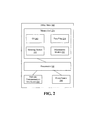
- FIG. 2 illustrates an example utility meter 205, according to an example embodiment of the invention.
- the utility meter 205 of FIG. 2 may be an example implementation of any one of the utility meters 105a-n of FIG. 1 .
- an example utility meter 205 may include any number of suitable computer processing components that facilitate the operation of the utility meter and/or the provision of a utility service and/or commodity (e.g., electricity, water, gas, etc.) to a location, including a customer home location.
- suitable processing devices that may be incorporated into a utility meter 205 include, but are not limited to, application-specific circuits, microcontrollers, minicomputers, other computing devices, and the like.
- a utility meter 205 may include any number of processors 232 that facilitate the execution of computer-readable instructions. By executing computer-readable instructions, the utility meter 205 may include or form a special purpose computer or particular machine that facilitates the provision of a utility service and/or the provision of a commodity to a location.
- the utility meter 205 may include one or more memory devices 234 and/or one or more network and/or communications interfaces 236.
- the one or more memory devices 234 or memories may include any suitable memory devices, for example, caches, read-only memory devices, random access memory devices, magnetic storage devices, etc.
- the one or more memory devices 234 may store data, executable instructions, and/or various program modules utilized by the utility meter 205, for example, data files 238, an operating system ("OS") 240, a metering module 242, and/or a prioritization module 243.
- OS operating system
- the data files 238 may include, for example, stored data associated with the operation of a utility meter 205, stored data associated with measurements and/or readings taken by the utility meter 205, utility meter configuration information, stored requests, messages and/or alerts, and/or stored commodity management, usage, and/or distribution data.
- the data files 238 can further provide information supporting packet or information prioritization.
- the data files 238 may include unique identifiers or other identifiers for battery-powered or limited power source network devices (e.g., home devices) that are connected or in communication with utility meter 205, such as any of devices 111a-n, 112a-n, 113a-n, or 114a-n.
- the data files 238 can maintain a MAC address or IP address for battery-powered or limited power source network devices.
- the OS 240 may include executable instructions and/or program modules that facilitate and/or control the general operation of the utility meter 205.
- the OS 240 may facilitate the execution of other software programs and/or program modules by the processors 232.
- the prioritization module 243 may be configured to identify one or more home devices that are battery-powered or associated with a limited power source. The determination may be utilized in conjunction with a network stack, as described herein, for example, to determine which priority buffer to place a packet or information in, or which packet or information to retrieve next from a searchable buffer.
- the one or more network interfaces 236 associated with the utility meter 205 can include a HAN / LAN interface and a NAN interface.
- the LAN interface can be used for communicating or connecting with one or more HANs / LANs such as HANs / LANs 110a-n of FIG. 1
- the NAN interface can be used for communicating or connecting with one or more NANs such as NANs 115a-n of FIG. 1 .
- a utility meter 205 may receive data from and/or communicate data to other components of the system 100.
- the one or more network interfaces 236, including the HAN / LAN interface and/or the NAN interface, can be implemented as one or more network cards, adaptors, or transceivers 237 for communicating over wired interfaces (e.g., power line carrier communications, serial communications link, USB, Ethernet, fiber optic, etc.) and/or wireless interfaces (e.g., ZigBee, GSM, Wi-Fi, WiMAX, Bluetooth, GRPS, cellular, 3G, 4G, 802.11x, RF mesh communications, etc.). It will be appreciated that the one or more network interfaces 236 can also be utilized for communicating or connecting with one or more other network devices or networks, including WAN 125 of FIG. 1 , without departing from example embodiments of the invention.
- wired interfaces e.g., power line carrier communications, serial communications link, USB, Ethernet, fiber optic, etc.
- wireless interfaces e.g., ZigBee, GSM, Wi-Fi, WiMAX, Bluetooth, GRPS, cellular
- the utility meter 205 can include or utilize a network stack to manage the flow of information between one or more HANs / LANs.
- a network stack in accordance with an example embodiment of the invention may include a lower network stack and an upper network stack.
- the lower network stack may include a PHY layer and a MAC layer while the upper network stack may include an LLC layer, a transport layer, and an application layer.
- a searchable buffer or multiple priority buffers may be provided between the lower network stack and the upper network stack, or may be implemented as part of either the lower network stack or the upper network stack.
- a first portion of the network stack may be implemented as part of the hardware of the network / communications interface(s) 236, and a second portion of the network stack may be implemented as part of the memory 234.
- the lower network stack may be implemented as part of network / communications interface(s) 236 while the upper network stack may be implemented as part of the memory 234.
- the example buffer(s), including a searchable buffer and/or the priority buffers, described herein may be implemented as either part of the network communications interface(s) 236 or the memory 234 (e.g., as part of prioritization module 243, OS 240, or another module). It will be appreciated that the variations of the example network stack are available in accordance with example embodiments of the invention.
- the PHY layer and the MAC layer may be integrated into a single layer.
- the upper network stack one or more of the LLC layer, a transport layer, and the application layer can be combined into a single layer.
- the logical separation of the different layers of the lower network stack and the upper network stack can be embodied in many forms to facilitate delivery, transport, and/or conversion of information between a physical network connection and a software application, or vice versa.
- Many variations of an example network stack are available without departing from example embodiments of the invention.
- the utility meter 205 may typically receive a commodity from a connected commodity line, grid and/or source, and likewise meter and distribute the commodity to an associated location, residence, business, household, or machine, including an associated network device 111a-n, 112a-n, 113a-n, 114a-n. Additionally, as desired in certain embodiments, the utility meter 205 may include any number of suitable power sources 244, which can include wired power supplies and solar power cells, as well as back-up power supplies such as one or more batteries, fuel cells, or one or more super capacitors.
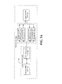
- FIG. 3A illustrate an example network stack 300 utilizing a plurality of priority buffers in accordance with an example embodiment of the invention.
- the example network stack 300 may be implemented as part of the network / communications interface(s) 236 and/or memory 234, according to an example embodiment of the invention.
- an example network stack 300 may include at least a lower network stack 305 and an upper network stack 310.
- the lower network stack 305 may include a physical (PHY) layer 315 (layer 1) and a MAC / Data Link Layer 320 (layer 2).
- PHY physical
- the upper network stack 310 may include a network layer 345 (layer 3), a transport layer 350 (layer 4), a session layer 355 (layer 5), a presentation layer 360 (layer 6), and an application layer 365 (layer 7).
- a plurality of receive (RX) buffers and transmit (TX) priority buffers may be configured, operable, or provided to facilitate transfer of data and information between the lower network stack 305 and the upper network stack 310.
- the RX buffers may receive and store data and information from the lower network stack 305 (e.g., MAC / Data Link Layer 320) until the upper network stack 310 has an opportunity to retrieve the data and information from the RX buffers for subsequent processing.
- the TX buffers may receive and store data and information from the upper network stack 310 until the lower network stack 305 has an opportunity to retrieve the data and information from the TX buffers for transmission to one or more network devices.
- RX priority buffer 325a may be a high priority RX first-in first-out (FIFO) buffer while RX priority buffer 325b may be a low priority RX FIFO buffer.
- RX priority buffer 325a may have priority over the data and information stored in low priority RX FIFO buffer 325b.
- the upper network stack 310 may retrieve data and information from high priority RX FIFO buffer 325a first for processing before retrieving data and information from low priority RX FIFO buffer 325b.
- the lower network stack 305 may deliver information or data received from limited power source network devices (or wireless devices) to the high priority RX FIFO buffer 325a.
- the lower network stack 305 may deliver information or data that is received from non-limited power source network devices (or wired devices) to the low priority RX FIFO buffer 325b.
- RX priority buffers there may be more than two RX priority buffers in accordance with alternative embodiments of the invention.
- TX priority buffer 330a may be a high priority TX FIFO buffer while TX priority buffer 330b may be a low priority TX FIFO buffer.
- the data and information stored in high priority TX FIFO buffer 330a may have priority over the data and information stored in low priority TX FIFO buffer 330b.
- the lower network stack 305 may retrieve data and information from the high priority TX FIFO buffer 330a first for delivery to one or more network devices before retrieving data and information from low priority TX FIFO buffer 330b. As will be described herein with respect to FIG.
- the upper network stack 310 may deliver information or data that is to be transmitted to limited power source network devices (or wireless devices) to the high priority TX FIFO buffer 330a.
- the upper network stack 310 may deliver information or data that is to be transmitted to non-limited power source network devices (or wired devices) to the low priority TX FIFO buffer 330b.
- the high priority TX buffer would take priority over the medium priority TX buffer, which itself would take priority over the low priority TX buffer.
- the upper network stack 310 may then deliver information or data to the appropriate priority TX buffer based upon the priority of delivery of the information or data.
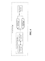
- FIG. 4 illustrates an alternative to the network stack of FIG. 3A-3B where searchable buffers may be utilized instead of priority buffers, according to an example embodiment of the invention.
- the lower network stack 305 and the upper network stack 310 in FIG. 4 are similar to those described with respect to FIGs. 3A-3B .
- the use of a searchable RX buffer 425 may eliminate the need for multiple RX priority buffers according to an example embodiment of the invention.
- the use of a searchable TX buffer 430 may eliminate the need for multiple TX priority buffers according to an example embodiment of the invention.
- searchable buffers 425, 430 may require that data or information stored in those buffers include one or more identifiers to designate, either directly or indirectly, the respective priority of the stored data or information.
- the identifier may be a unique address such as a MAC address or IP address associated with the source or destination of the stored data or information.
- the unique address can then be referenced with one or more lists, records, or tables, perhaps in memory 234 or another storage location, that identifies those unique addresses associated with, for example, a high-priority status (e.g., a limited power source network device, a wireless network device, etc.) or a low-priority status (e.g., a non-limited power source network device, a wired network device, etc.), according to an example embodiment of the invention.
- a high-priority status e.g., a limited power source network device, a wireless network device, etc.
- a low-priority status e.g., a non-limited power source network device, a wired network device, etc.
- the identifier can be a socket port number and/or communications protocol (e.g., UDP, TCP, etc.).
- a first socket port number and/or first communications protocol e.g., UDP
- a second socket port number and/or second communications protocol e.g., TCP
- a low-priority status e.g., a non-limited power source network device, a wired network device, etc.
- FIGs. 3A-3B and 4 have been described with respect to buffers, it will be that these buffers may include one or more other types of memories or memory devices beyond traditional buffers.
- the buffers can also include queues, caches, and other types of random access memory without departing from example embodiments of the invention.
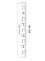
- FIG. 5 illustrates an example flow diagram of a method for communications prioritization for a utility meter, according to an example embodiment of the invention.
- the operations of the method 500 may be performed by the example utility meter 205 of FIG. 2 .
- the operations of the method 500 may be implemented as computer-executable instructions (e.g., available in a memory 234, an interface 236 memory, a processor 232 memory, etc.) and/or specialized hardware executed by a network / communications interface 236 (e.g., a radio), a processor 232, or a combination thereof.
- a network / communications interface 236 e.g., a radio
- the example utility meter 205 of FIG. 2 is representative of any of the utility meters 105a-n of FIG.
- the operations of the method 500 of FIG. 5 can likewise be performed by any of the utility meters 105a-n, or other utility meters in accordance with embodiments of the invention.
- the method 500 of FIG. 5 will be discussed as being performed by the example utility meter 105a.
- the example utility meter 105a may be in communication with one or more network devices 111a-n, which when located in, near, or around a customer home, can be referred to as a home device.
- These network devices 111a-n may include lights, appliances (e.g., refrigerator, stove, oven, dishwasher, clothes washer, clothes dryer, coffee maker, etc.), televisions, security systems, air conditioning and/or heating units, home Internet modems and routers.
- network devices 111a-n can also be located outside of a customer home or location, and can communicate with the example utility meter using wired or wireless communications without departing from example embodiments of the invention.
- the example utility meter 105a may be in communication with one or more other network devices via a NAN such as NAN 115a, or alternatively, other NANs 115b-n or WAN 125.
- these other network devices can include other utility meters 105b-n, gateway computer 120a-n, routing or switching devices, or other computing devices, and the like.
- the example method 500 may likewise be performed by any of utility meters 105b-n without departing from example embodiments of the invention.
- information may be received or generated by the network stack of the utility meter 105a.
- the information may be in different formats depending upon whether it is information received from one or more network devices (e.g., network devices 111a-n) or information received or generated for transmission to one or more network devices, which may include one or more home devices.
- information received from one or more network devices by a lower network stack 305 may be in the form of a packet or frame, according to an example embodiment of the invention.
- block 510 may determine whether the received information is associated with a transmitting network device that is battery-powered or otherwise associated with a limited power source. To make this determination, block 510 may examine the received information to determine whether the information itself includes any specific identifier or code that designates the received information as being associated with a network device that is battery-powered or otherwise associated with a limited source of power.
- block 510 can also obtain the unique address or identifier (e.g., IP address, MAC address, etc.) of the transmitting network device, and utilize a stored high priority list, record or table in memory 234 or another location to identify whether the unique address or identifier is associated with a network device that is battery-powered or otherwise associated with a limited source of power.
- block 510 may also determine whether the received information is associated with a transmitting network device that is communicating via wireless communications. To do so, block 510 may determine, for example, whether the received information was received from a network / communications interface 236 that is known to be a wireless interface (e.g., Zigbee, WiFi, 802.11x, etc.).
- block 510 can also obtain the unique address or identifier (e.g., IP address, MAC address, etc.) of the transmitting network device, and utilize a stored high priority list, record or table in memory 234 or another location to identify whether the unique address or identifier is associated with a network device that transmits wirelessly.
- the unique address or identifier e.g., IP address, MAC address, etc.
- the information received at block 510 may be received or generated by the upper network stack 310 of utility meter 105a for transmission to a network device.
- block 510 may determine whether information for transmission is destined for a receiving network device that is battery-powered or otherwise associated with a limited power source. To make this determination, block 510 can obtain the unique destination address or identifier (e.g., IP address, MAC address, etc.) of the receiving network device, and utilize a stored high priority list, record or table in memory 234 or another location to identify whether the unique address or identifier is associated with a network device that is battery-powered or otherwise associated with a limited source of power.
- the unique destination address or identifier e.g., IP address, MAC address, etc.
- block 510 may also determine whether the received information is associated with a transmitting network device that is communicating via wireless communications. To do so, block 510 may obtain the unique destination address or identifier (e.g., IP address, MAC address, etc.) of the receiving network device, and utilize a stored high priority list, record or table in memory 234 or another location to identify whether the unique address or identifier is associated with a network device that receives wirelessly. Alternatively, if the information is designated for transmission from a network / communications interface 236 that is known to be a wireless interface (e.g., Zigbee, WiFi, 802.11x, etc.), the block 510 can also determine that the information is for transmission to a receiving network device that is communicating via wireless communications. Many variations of block 510 are available without departing from example embodiments of the invention.
- a network / communications interface 236 that is known to be a wireless interface (e.g., Zigbee, WiFi, 802.11x, etc.)
- the block 510 can also determine that
- block 510 determines that the received information is associated with a network device that is battery-powered or otherwise associated with a limited source of power (or alternatively, a wireless network device), then processing may proceed to block 515, where the information is identified high priority information that should take priority for delivery or processing over lower priority information.
- block 515 may include providing or including an identifier or code with the information to indicate or designate its high priority status, perhaps where a searchable buffer (e.g., buffer 425, 430) is being utilized.
- a searchable buffer e.g., buffer 425, 430
- block 510 may otherwise determine that the received information is associated with a network device that is not battery-powered or otherwise not associated with a limited source of power (or alternatively, is a wired network device), and processing may proceed to block 520.
- the information may be identified as low priority information that is of a lesser priority for delivery or processing compared to high priority information.
- the information may be placed in the appropriate buffer based upon the identified priority at block 515 or block 520.
- the information can be placed in an appropriate RX buffer such as one of the RX priority buffers 325a, 325b, or searchable RX buffer 425.
- the information can be placed in an appropriate TX buffer such as one of the TX priority buffers 330a, 330b, or searchable TX buffer 430.
- high priority information that is received from a transmitting network device may be placed in high priority RX FIFO buffer 325a, while low priority information that is received from a transmitting network device may be placed in a low priority RX FIFO buffer 325b.
- high priority information that is for transmission to a receiving network device may be placed in high priority TX FIFO buffer 330a while low-priority information that is for transmission to a receiving network device may be placed in low priority TX FIFO buffer 330b.
- the information may include an identifier or code with the information to indicate or designate its priority (e.g., high priority, low priority, etc.).
- the unique address (e.g., IP address, MAC address) may serve as the identifier or code for designating the priority of the information, and no additional identifier or code may be needed, according to an example embodiment of the invention. It will be appreciated that in some example embodiments, only a high priority status may be designated with the implicit knowledge that a lack of a priority status may indicate a lower priority status, or vice versa.
- information may be retrieved and/or processed from the buffers. More specifically, high priority information may be retrieved or received and processed from the buffers ahead of lower priority information.
- the upper network stack 310 may initially retrieve or receive information for processing from high priority RX FIFO buffer 325a until the buffer 325a is empty. Once the high priority RX FIFO buffer 325a is empty, then the upper network stack 310 may retrieve information for processing from the low priority RX FIFO buffer 325b.
- the lower network stack 305 may initially retrieve or receive information for processing / delivery from the high-priority TX FIFO buffer 330a until the buffer 330a is empty.
- the lower network stack 305 may retrieve information for processing from the low priority TX FIFO buffer 330b.
- the buffers 325a, 325b, 330a, 330b may be FIFO buffers in which case information may be retrieved from the respective buffers on a first-in, first-out basis, as appreciated by those of ordinary skill in the art.
- Block 530 may operate slightly differently if searchable buffers such as buffers 425, 430 are utilized instead of priority buffers.
- the upper network stack 310 may retrieve or receive information for processing from searchable RX buffer 425
- the lower network stack 305 may retrieve or receive information for processing from searchable TX buffer 430.
- both high priority information and low priority information may both be stored in respective searchable buffers 425, 430, and as such, the retrieval of the information may require additional analysis of the stored information.
- the respective buffer may be searched to identify an identifier or code, or lack thereof, included with the stored information to designate a high-priority status.
- the respective buffers 425, 430 may be searched for stored information having a unique address or identifier (e.g., IP address, MAC address, etc.) associated with a source or destination network device that is associated with a high priority status (e.g., a battery-powered or limited power source device, or alternatively, a wireless device). Accordingly, the high priority information may be retrieved from buffers 425, 430 for processing and/or delivery ahead of the low priority information stored in the respective buffer.
- a unique address or identifier e.g., IP address, MAC address, etc.
- the buffers 425, 430 may still be FIFO buffers insofar as the first set of high priority information may be processed in a first in, first out manner, while the second set of low priority information may likewise be processed in a first in, first out manner, where all of the first set of high priority information may be processed ahead of the second set of low priority information, according to an example embodiment of the invention.
- the operations described and shown in the method 500 of FIG. 5 may be carried out or performed in any suitable order as desired in various embodiments of the invention. Additionally, in certain embodiments, at least a portion of the operations may be combined or carried out in parallel. Furthermore, in certain embodiments, less than or more than the operations described in FIG. 5 may be performed. As desired, the operations set forth in the method 500 may be performed in a loop for continuous monitoring.
- These computer-executable program instructions may be loaded onto a general purpose computer, a special-purpose computer, a processor, or other programmable data processing apparatus to produce a particular machine, such that the instructions that execute on the computer, processor, or other programmable data processing apparatus create means for implementing one or more functions specified in the flow diagram block or blocks.
- These computer program instructions may also be stored in a computer-readable memory that can direct a computer or other programmable data processing apparatus to function in a particular manner, such that the instructions stored in the computer-readable memory produce an article of manufacture including instruction means that implement one or more functions specified in the flow diagram block or blocks.
- embodiments of the invention may provide for a computer program product, comprising a computer-usable medium having a computer- readable program code or program instructions embodied therein, said computer-readable program code adapted to be executed to implement one or more functions specified in the flow diagram block or blocks.
- the computer program instructions may also be loaded onto a computer or other programmable data processing apparatus to cause a series of operational elements or steps to be performed on the computer or other programmable apparatus to produce a computer-implemented process such that the instructions that execute on the computer or other programmable apparatus provide elements or steps for implementing the functions specified in the flow diagram block or blocks.
- blocks of the block diagrams and flow diagrams support combinations of means for performing the specified functions, combinations of elements or steps for performing the specified functions and program instruction means for performing the specified functions. It will also be understood that each block of the block diagrams and flow diagrams, and combinations of blocks in the block diagrams and flow diagrams, can be implemented by special-purpose, hardware-based computer systems that perform the specified functions, elements or steps, or combinations of special purpose hardware and computer instructions.
Landscapes
- Engineering & Computer Science (AREA)
- Computer Networks & Wireless Communication (AREA)
- Signal Processing (AREA)
- Health & Medical Sciences (AREA)
- Computing Systems (AREA)
- General Health & Medical Sciences (AREA)
- Medical Informatics (AREA)
- Automation & Control Theory (AREA)
- Mobile Radio Communication Systems (AREA)
- Small-Scale Networks (AREA)
- Arrangements For Transmission Of Measured Signals (AREA)
Applications Claiming Priority (1)
| Application Number | Priority Date | Filing Date | Title |
|---|---|---|---|
| US13/028,142 US9124614B2 (en) | 2011-02-15 | 2011-02-15 | Methods and apparatuses for utility meters or other devices with communications prioritization |
Publications (2)
| Publication Number | Publication Date |
|---|---|
| EP2490464A2 true EP2490464A2 (de) | 2012-08-22 |
| EP2490464A3 EP2490464A3 (de) | 2013-08-28 |
Family
ID=45607051
Family Applications (1)
| Application Number | Title | Priority Date | Filing Date |
|---|---|---|---|
| EP12155225.1A Withdrawn EP2490464A3 (de) | 2011-02-15 | 2012-02-13 | Verfahren und Vorrichtung für Verbrauchszähler oder andere Vorrichtungen mit Kommunikationspriorisierung |
Country Status (7)
| Country | Link |
|---|---|
| US (1) | US9124614B2 (de) |
| EP (1) | EP2490464A3 (de) |
| JP (1) | JP2012170072A (de) |
| AU (1) | AU2012200823A1 (de) |
| BR (1) | BR102012003337A2 (de) |
| CA (1) | CA2767506A1 (de) |
| NZ (1) | NZ598190A (de) |
Cited By (1)
| Publication number | Priority date | Publication date | Assignee | Title |
|---|---|---|---|---|
| EP3926902A4 (de) * | 2019-12-10 | 2022-06-22 | ENN Digital Energy Technology Co., Ltd | Verfahren und system zur datenübertragung im internet der dinge |
Families Citing this family (9)
| Publication number | Priority date | Publication date | Assignee | Title |
|---|---|---|---|---|
| US10326537B2 (en) | 2006-01-31 | 2019-06-18 | Silicon Laboratories Inc. | Environmental change condition detection through antenna-based sensing of environmental change |
| US20150187209A1 (en) | 2006-01-31 | 2015-07-02 | Sigma Designs, Inc. | Method and system for synchronization and remote control of controlling units |
| US10277519B2 (en) * | 2006-01-31 | 2019-04-30 | Silicon Laboratories Inc. | Response time for a gateway connecting a lower bandwidth network with a higher speed network |
| US9019864B2 (en) * | 2011-02-14 | 2015-04-28 | General Electric Company | System and method of wireless enabled device configuration over an advanced metering infrastructure (AMI) |
| US9066362B2 (en) * | 2013-03-08 | 2015-06-23 | Qualcomm Incorporated | Prioritizing time critical data for transmission during power limited state in DC-HSUPA operation |
| US10885583B2 (en) * | 2013-12-19 | 2021-01-05 | Chicago Mercantile Exchange Inc. | Deterministic and efficient message packet management |
| US10637681B2 (en) | 2014-03-13 | 2020-04-28 | Silicon Laboratories Inc. | Method and system for synchronization and remote control of controlling units |
| US10637673B2 (en) | 2016-12-12 | 2020-04-28 | Silicon Laboratories Inc. | Energy harvesting nodes in a mesh network |
| CN110278547B (zh) * | 2018-03-13 | 2022-04-08 | 博通集成电路(上海)股份有限公司 | 用于建立低功耗蓝牙网状网络的装置和方法 |
Family Cites Families (6)
| Publication number | Priority date | Publication date | Assignee | Title |
|---|---|---|---|---|
| US7248158B2 (en) * | 2000-04-14 | 2007-07-24 | Current Technologies, Llc | Automated meter reading power line communication system and method |
| US6397061B1 (en) * | 2000-06-24 | 2002-05-28 | Motorola, Inc. | Method and apparatus to reprioritize data transfer in a short range Ad Hoc network |
| US7069457B2 (en) * | 2002-06-28 | 2006-06-27 | Intel Corporation | Automatic mobile device scalable synchronization based on battery state |
| JP4078952B2 (ja) | 2002-11-01 | 2008-04-23 | 日本電気株式会社 | 無線端末アクセスシステム |
| JP2006180174A (ja) * | 2004-12-22 | 2006-07-06 | Fujitsu Ltd | 移動体端末制御プログラムおよび移動体端末装置 |
| US7301480B2 (en) * | 2005-05-27 | 2007-11-27 | Chamberlain Group, Inc. | System and method for prioritizing sensors in a barrier operator system |
-
2011
- 2011-02-15 US US13/028,142 patent/US9124614B2/en active Active
-
2012
- 2012-02-13 JP JP2012027902A patent/JP2012170072A/ja active Pending
- 2012-02-13 EP EP12155225.1A patent/EP2490464A3/de not_active Withdrawn
- 2012-02-13 AU AU2012200823A patent/AU2012200823A1/en not_active Abandoned
- 2012-02-13 NZ NZ598190A patent/NZ598190A/xx not_active IP Right Cessation
- 2012-02-14 CA CA2767506A patent/CA2767506A1/en not_active Abandoned
- 2012-02-14 BR BRBR102012003337-2A patent/BR102012003337A2/pt not_active Application Discontinuation
Non-Patent Citations (1)
| Title |
|---|
| None |
Cited By (1)
| Publication number | Priority date | Publication date | Assignee | Title |
|---|---|---|---|---|
| EP3926902A4 (de) * | 2019-12-10 | 2022-06-22 | ENN Digital Energy Technology Co., Ltd | Verfahren und system zur datenübertragung im internet der dinge |
Also Published As
| Publication number | Publication date |
|---|---|
| BR102012003337A2 (pt) | 2013-07-30 |
| AU2012200823A1 (en) | 2012-08-30 |
| US9124614B2 (en) | 2015-09-01 |
| CA2767506A1 (en) | 2012-08-15 |
| US20120207179A1 (en) | 2012-08-16 |
| EP2490464A3 (de) | 2013-08-28 |
| NZ598190A (en) | 2013-08-30 |
| JP2012170072A (ja) | 2012-09-06 |
Similar Documents
| Publication | Publication Date | Title |
|---|---|---|
| US9124614B2 (en) | Methods and apparatuses for utility meters or other devices with communications prioritization | |
| EP2498060B1 (de) | System, Verfahren und Vorrichtungen zur Verringerung von Netzwerküberlastung in einem intelligenten Versorgungszählersystem | |
| US8724490B2 (en) | Zigbee IP/6LowPan router | |
| CN105934976B (zh) | 主从网络休眠及唤醒的方法、装置及主从网络省电系统 | |
| CN106340176B (zh) | 一种智能电表的信息共享方法、智能电表及采集路由器 | |
| CN102184628B (zh) | 一种智能分区的低功耗无线组网抄表方法 | |
| EP2936749A1 (de) | Überbrückung von netzwerkvorrichtungen in einem hybriden kommunikationsnetz | |
| US8847784B2 (en) | Systems, methods, and apparatuses for determining power usage with a meter | |
| CN102907123A (zh) | 控制装置、中继方法及其程序 | |
| US8711710B2 (en) | Systems and methods for adaptive error thresholds or adaptive modulation schemes based on atmospheric conditions | |
| EP2530890B1 (de) | Verstärkerdurchgangsnachrichtenübermittlung | |
| CN205510063U (zh) | 遥控遥测系统 | |
| CA3141696C (en) | Actor-based data processing | |
| US8670308B2 (en) | Meters with multiple network interfaces | |
| CN202339604U (zh) | 多抄表方式单相费控智能电能表 | |
| US9232411B2 (en) | Systems and methods for routing home area network (HAN) messages | |
| CN102098225A (zh) | 带宽控制方法、装置和网桥 | |
| Chang et al. | Energy/carbon management network for IT equipments | |
| KR20140129939A (ko) | 홈 영역 네트워크에서 배터리 운영 기기를 위한 데이터 미러링 시스템 | |
| KR20140129941A (ko) | 데이터 미러 기기 장치 및 시스템 | |
| KR20140129940A (ko) | 배터리 운영 기기 장치 및 시스템 | |
| KR20140129938A (ko) | 홈 영역 네트워크에서 배터리 운영 기기와의 통신을 위한 데이터 미러링 방법 |
Legal Events
| Date | Code | Title | Description |
|---|---|---|---|
| PUAI | Public reference made under article 153(3) epc to a published international application that has entered the european phase |
Free format text: ORIGINAL CODE: 0009012 |
|
| AK | Designated contracting states |
Kind code of ref document: A2 Designated state(s): AL AT BE BG CH CY CZ DE DK EE ES FI FR GB GR HR HU IE IS IT LI LT LU LV MC MK MT NL NO PL PT RO RS SE SI SK SM TR |
|
| AX | Request for extension of the european patent |
Extension state: BA ME |
|
| PUAL | Search report despatched |
Free format text: ORIGINAL CODE: 0009013 |
|
| AK | Designated contracting states |
Kind code of ref document: A3 Designated state(s): AL AT BE BG CH CY CZ DE DK EE ES FI FR GB GR HR HU IE IS IT LI LT LU LV MC MK MT NL NO PL PT RO RS SE SI SK SM TR |
|
| AX | Request for extension of the european patent |
Extension state: BA ME |
|
| RIC1 | Information provided on ipc code assigned before grant |
Ipc: H04W 4/00 20090101AFI20130719BHEP Ipc: H04L 12/28 20060101ALI20130719BHEP |
|
| 17P | Request for examination filed |
Effective date: 20140228 |
|
| RBV | Designated contracting states (corrected) |
Designated state(s): AL AT BE BG CH CY CZ DE DK EE ES FI FR GB GR HR HU IE IS IT LI LT LU LV MC MK MT NL NO PL PT RO RS SE SI SK SM TR |
|
| STAA | Information on the status of an ep patent application or granted ep patent |
Free format text: STATUS: THE APPLICATION IS DEEMED TO BE WITHDRAWN |
|
| 18D | Application deemed to be withdrawn |
Effective date: 20150901 |