EP2490091B1 - Verfahren und Vorrichtung zur Gierkontrolle eines Luftfahrzeugs - Google Patents
Verfahren und Vorrichtung zur Gierkontrolle eines Luftfahrzeugs Download PDFInfo
- Publication number
- EP2490091B1 EP2490091B1 EP12154827.5A EP12154827A EP2490091B1 EP 2490091 B1 EP2490091 B1 EP 2490091B1 EP 12154827 A EP12154827 A EP 12154827A EP 2490091 B1 EP2490091 B1 EP 2490091B1
- Authority
- EP
- European Patent Office
- Prior art keywords
- rudder
- gmax
- dmax
- aircraft
- rotation
- Prior art date
- Legal status (The legal status is an assumption and is not a legal conclusion. Google has not performed a legal analysis and makes no representation as to the accuracy of the status listed.)
- Active
Links
Images


Classifications
-
- G—PHYSICS
- G05—CONTROLLING; REGULATING
- G05D—SYSTEMS FOR CONTROLLING OR REGULATING NON-ELECTRIC VARIABLES
- G05D1/00—Control of position, course, altitude or attitude of land, water, air or space vehicles, e.g. using automatic pilots
- G05D1/0055—Control of position, course, altitude or attitude of land, water, air or space vehicles, e.g. using automatic pilots with safety arrangements
- G05D1/0066—Control of position, course, altitude or attitude of land, water, air or space vehicles, e.g. using automatic pilots with safety arrangements for limitation of acceleration or stress
Definitions
- the present invention relates to a method and a device for controlling a yawning aircraft.
- the yaw control of an aircraft is mainly provided by an articulated rudder, rotatable in two opposite directions of rotation between an aerodynamically neutral position and a stopped position of maximum rotation.
- the rudder is controlled by a movable control device (rudder) available to the pilot of the aircraft.
- This member is generally provided with two pedals whose respective depressions cause the displacement of said member in two opposite directions respectively associated with the two opposite directions of rotation of the rudder.
- this lifter controls the rotation of the rudder so that the amplitude of the rotation of said rudder depends on the amplitude of the displacement of said rudder.
- a depression of the right pedal reflects the will of the pilot to generate a moment of yaw tending to move the nose of the aircraft to the right, this moment being obtained by a deflection to the right of the rudder.
- the pilot of the aircraft wishes to correct the lateral trajectory of the aircraft, he can act on the rudder in order to intervene the rudder.
- the object of the present invention is therefore to prevent such a risk for the aircraft during a yaw operation.
- the duration of the first time interval is at most equal to 3 seconds. It has been found that a duration of between 1 and 2 seconds is a satisfactory compromise between, on the one hand, the detection of a control reversal of the rudder and, on the other hand, the triggering speed of the rudder. the alert.
- the alarm can be triggered only when the speed of said aircraft is at least equal to an alert speed threshold itself greater than the limiting speed threshold.
- the alert can be triggered only at high speeds of the aircraft, precisely where the risks incurred by reversing yaw are greatest.
- the alert can be maintained for a second time interval of predetermined duration at least approximately equal to 5 seconds.
- the alert can be triggered in the form of a visual or audible signal to the pilot.
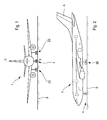
- the aircraft 1 shown schematically on the Figures 1 and 2 and rolling on the ground S, comprises a pair of 2G and 2D main wheel trains, as well as a front steering gear 4, disposed near the nose of the aircraft 1 and a rudder 5 disposed at the rear of said aircraft 1.
- the wheel trains 2G and 2D respectively arranged on the left and right of the aircraft 1, are symmetrical to each other with respect to the median longitudinal vertical plane VV of said aircraft 1.
- the rudder 5 is articulated and can rotate in two opposite directions of rotation G (left) and D (right), about a vertical axis XX belonging to the plane VV.
- the angle of rotation of the rudder 5, with respect to an axis ZZ belonging to a plane (YY, ZZ) orthogonal to the axis of rotation XX of said rudder, is designated by the reference ⁇ .
- the rudder 5 is pivotable, in each of the two directions of rotation G and D, between an aerodynamically neutral position, corresponding to an angle ⁇ 0 (of zero value), and a stopped position of maximum rotation, designated by ⁇ Gmax (positive value) for a rotation in the direction G (to the left) and by ⁇ Dmax (of negative value) for a rotation in the direction D (to the right).
- the total amplitude of potential rotation of the rudder 5 is therefore equal to ⁇ Gmax - ⁇ Dmax .
- ⁇ Gmax is the opposite of ⁇ Dmax and the total amplitude is therefore equal to 2. ⁇ Gmax .
- the aircraft 1 is provided with a movable control member 6 - or lifter - at the disposal of the pilot of said aircraft.
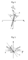
- the control member 6 is intended, when the aircraft 1 rolls on the ground S or is in flight, to control the rotation of the rudder 5 of said aircraft (see FIG. figure 4 ), around the XX axis, in both directions G and D.
- control member 6 is able to turn about a vertical axis BB (considered in a reference frame (AA, BB, CC) that may be different from the reference frame (XX YY, ZZ) of the control surface. direction 5), in two opposite directions of rotation which are respectively associated with the two directions of rotation G and D of the rudder 5.
- the control member 6 is therefore provided with two pedals respectively left 7G and 7D right, a depression of the left pedal 7G being adapted to generate a rotation of the control member 6 in the direction of rotation associated with the direction of rotation to the left G of the rudder 5, while a depression of the pedal of 7D is adapted to generate a rotation of said control member 6 in the direction of rotation associated with the direction of rotation to the right D of said rudder 5.
- the movable control member 6 can thus pivot (see figure 5 ) about the axis BB, between a position (of angle ⁇ zero) for which it is not controlled rotation of the rudder 5 and a stopped position (of angle ⁇ equal to ⁇ Gmax ) for which the rotation of said member 6 is maximum. Between these two positions, the movable control member 6 passes through a position (of angle ⁇ equal to ⁇ G ( ⁇ Gmax )) for which the stopped position of maximum rotation ⁇ Gmax to the left of the rudder 5 is reached.
- the movable control member 6 can pivot about the axis BB, between a position (of zero angle ⁇ ) for which it is not controlled rotation of the rudder 5 and a stopped position ( angle ⁇ equal to ⁇ Dmax ) for which the rotation of said member 6 is maximum. Between these two positions, the movable control member 6 passes through a position (of angle ⁇ equal to ⁇ D ( ⁇ Dmax )) for which the stopped position of maximum rotation ⁇ Dmax to the right of the rudder 5 is reached.
- the yaw control device of the aircraft 1, according to the present invention is arranged between the movable control member 6 and the rudder 5 so that the amplitude ⁇ of the rotation of said rudder 5 depends on the amplitude ⁇ of the displacement of said movable control member 6.
- a transducer 9 is associated with the control member 6, so as to measure the amplitude ⁇ of displacement in rotation of said member.
- the pilot with his left foot (or right), presses the left pedal 7G (or right 7D), the displacement in translation of said pedal is transformed into a rotational movement of the organ mobile control 6, the amplitude ⁇ of this displacement being able to be measured by the transducer 9.
- This command ⁇ is addressed to an adder 11, to which orders are also sent from a yaw damper 12 and an autopilot 13.
- a yaw damper 12 is activated, account is taken of the control ⁇ addressed by the movable control member 6 when said damper 12 dampens the yaw operation of the aircraft 1.
- This command ⁇ is then addressed to a limiter 14, the function of which is to limit the displacement in rotation ⁇ addressed by the mobile control member 6 to values respectively ⁇ G ( ⁇ Gmax ) and ⁇ D ( ⁇ Dmax ) for which the stopped positions of maximum rotation ⁇ Gmax and ⁇ Dmax of the rudder 5 are reached in the two directions of rotation G and D, respectively, as a function of the speed V of the aircraft 1, from a threshold of limitation speed VminL previously determined (which may be for example equal to 165 knots).
- the displacement of the control member 6 may respectively exceed the positions ⁇ G ( ⁇ Gmax ) and ⁇ D ( ⁇ Dmax ) thereof respectively corresponding to the stopped positions of maximum rotation ⁇ Gmax and ⁇ Dmax of the rudder 5.
- the resulting control command ⁇ ' is then transmitted to a plurality of actuators 15.1, 15.2 and 15.3 of the rudder 5, in order to adjust the rotation amplitude ⁇ of said rudder, said amplitude of rotation ⁇ being an increasing function of the resulting control command ⁇ 'and, consequently, of the command ⁇ .
- the command ⁇ is also addressed to the warning system 16, shown in more detail on the figure 6 .
- This system comprises, firstly, in a similar manner to the limiter 14, a computer 20 intended to calculate the new values of stopped positions of maximum rotation ⁇ Gmax and ⁇ Dmax of the rudder 5, as a function of the speed V of the 1 and the VminL limitation speed threshold previously determined.
- the displacement limits ⁇ G ( ⁇ Gmax ) and ⁇ D ( ⁇ Dmax ) are then estimated from the values ⁇ Gmax and ⁇ Dmax (via the increasing function which links the amplitude of the rotation ⁇ of the control surface direction 5 to the command ⁇ ).
- the displacement limits ⁇ G ( ⁇ Gmax ) and ⁇ D ( ⁇ Dmax ) are fractions respectively displacements ⁇ Gmax and ⁇ Dmax of the movable control member 6, respectively in the two directions of rotation G and D, for which these the latter are in the stopped positions, and the pilot can therefore exceed said displacement limits ⁇ G ( ⁇ Gmax ) and ⁇ D ( ⁇ Dmax ).
- ⁇ G ( ⁇ Gmax ) and ⁇ D ( ⁇ max ) are addressed to two binary comparators 23 and 24, respectively types "A>B" and "A ⁇ B".
- ⁇ G ( ⁇ Gmax ) is equal to ⁇ D ( ⁇ Dmax ) and these two values will be designated by the reference ⁇ max .
- the first binary comparator 23 compares the values of ⁇ and ⁇ max and outputs a state OD, which is '1' when ⁇ is at least equal to ⁇ max and '0' otherwise.
- the latter ⁇ max is transformed - ⁇ max by means 21 and 22 (multiplier) for multiplying ⁇ max by the value '-1'.
- the second binary comparator 24 compares the values of ⁇ and - ⁇ max and outputs a state OG, which is '1' when ⁇ at most equal to - ⁇ max and '0' otherwise.
- the states OG and OD thus make it possible to determine whether the pilot has moved one of the control members 6G or 6D so that the displacement of said member 6G or 6D exceeds the position ⁇ G ( ⁇ Gmax ) (- ⁇ max negative) or ⁇ D ( ⁇ Dmax ) ( ⁇ max positive) thereof corresponding to the stopped position of maximum rotation ⁇ Gmax or ⁇ Dmax in one of the rotation directions G or D of the rudder 5.
- the torque ⁇ OG, OD ⁇ is ⁇ 0,1 ⁇ when ⁇ is at least equal to ⁇ max (overshoot of the left control member 6G), ⁇ 1, O ⁇ when ⁇ is at most equal to - ⁇ max (over-control of the right control member 6D) and ⁇ O, O ⁇ otherwise.
- a first gate "AND" 27 addressing a DG state, and to which are addressed, on the one hand, the state OG without delay and, on the other hand, the state OD with a time delay equal to the duration T1 above (via a retarder 26).
- the duration T1 is determined in such a way that, on the one hand, account is taken of the need to have a high alerting speed and, on the other hand, it can be determined with certainty that Over-order reversal has been initiated.
- a duration T1 at most equal to 3 seconds - or preferably between 1 and 2 seconds - proves particularly adequate.
- the yaw control device in the warning system 16, means for triggering said alert manually, for example for operating tests without for all that need to actually perform a yaw reversal.
- it can be made available to the pilot a test button 35. Therefore, if, simultaneously, at the "AND" gate 37, the pilot presses this test button 35 and the front wheel train 4 of the aircraft 1 is compressed (which is determined by the module 36), the alert can be triggered in the same way as described above with reference to the elements 38, 17 and 18.
- the triggering of the alert can be performed either manually or consecutively upon the detection of a reversal of over-control.
Landscapes
- Engineering & Computer Science (AREA)
- Aviation & Aerospace Engineering (AREA)
- Radar, Positioning & Navigation (AREA)
- Remote Sensing (AREA)
- Physics & Mathematics (AREA)
- General Physics & Mathematics (AREA)
- Automation & Control Theory (AREA)
- Mechanical Control Devices (AREA)
- Regulating Braking Force (AREA)
- Traffic Control Systems (AREA)
Claims (8)
- Verfahren zur Giersteuerung eines Luftfahrzeugs (1), wobei das Luftfahrzeug aufweist:- ein angelenktes Seitenruder (5), das sich in zwei entgegengesetzten Drehrichtungen (G, D) zwischen einer aerodynamisch neutralen Position (θ0) und einer arretierten Position maximaler Drehung (θGmax, θDmax) drehen kann; und- ein bewegliches Steuerorgan (6), das dem Piloten des Luftfahrzeugs (1) zur Verfügung steht, zur Steuerung des Seitenruders (5), wobei das Steuerorgan (6) in zwei entgegengesetzten Richtungen (G, D) bewegt werden kann, wobei die eine dieser Richtungen (G) einer (G) der Drehrichtungen des Seitenruders (5) zugeordnet ist, während die entgegengesetzte Richtung (D) der entgegengesetzten Drehrichtung (D) des Seitenruders (5) zugeordnet ist, wobei die Größe (θ) der Drehung des Seitenruders (5) von der Größe (β) der Bewegung des Steuerorgans (6) abhängt und die Bewegungen des Steuerorgans (6) über die Positionen (βG(θGmax), βD(θDmax)) desselben hinaus erfolgen können, die jeweils einer der arretierten Positionen maximaler Drehung (θGmax, θDmax) des Seitenruders (5) entsprechen, dadurch gekennzeichnet, dass, wenn der Pilot zuvor das Steuerorgan (6) derart bewegt hat, dass die Bewegung des Organs (6) über die Position (βG(θGmax)) desselben hinaus erfolgt, die der arretierten Position maximaler Drehung (θGmax) in der einen (G) der Drehrichtungen des Seitenruders (5) entspricht, ein Alarm ausgelöst wird, falls in einem ersten Zeitintervall von vorbestimmter Dauer (T1) der Pilot das Steuerorgan (6) derart bewegt, dass die Bewegung des Organs (6) über die Position (βD(θDmax)) desselben hinaus erfolgt, die der arretierten Position maximaler Drehung (θDmax) in der entgegengesetzten Drehrichtung (D) des Seitenruders (5) entspricht, wobei die Dauer (T1) derart bestimmt wird, dass einerseits die Notwendigkeit berücksichtigt wird, über eine erhöhte Geschwindigkeit einer Alarmauslösung zu verfügen, und andererseits auf sichere Weise bestimmt werden kann, dass eine Umkehrung einer Übersteuerung veranlasst worden ist.
- Verfahren nach Anspruch 1,
dadurch gekennzeichnet, dass die Dauer (T1) des ersten Zeitintervalls höchstens 3 Sekunden beträgt. - Verfahren nach Anspruch 2,
dadurch gekennzeichnet, dass die Dauer (T1) des ersten Zeitintervalls zwischen 1 und 2 Sekunden beträgt. - Verfahren nach einem der vorhergehenden Ansprüche, wobei die Bewegung des Steuerorgans (6) nur dann über die Positionen (βG(θGmax), βD(θDmax)) desselben, die jeweils einer der arretierten Positionen maximaler Drehung (θGmax, θDmax) des Seitenruders (5) entsprechen, hinaus erfolgen kann, wenn die Geschwindigkeit (V) des Luftfahrzeugs (1) mindestens gleich einem Begrenzungs-Geschwindigkeitsschwellenwert (VminL) ist,
dadurch gekennzeichnet, dass der Alarm nur dann ausgelöst wird, wenn die Geschwindigkeit (V) des Luftfahrzeugs (1) mindestens gleich einem Alarm-Geschwindigkeitsschwellenwert (VminA) ist, der seinerseits größer als der Begrenzungs-Geschwindigkeitsschwellenwert (VminL) ist. - Verfahren nach einem der vorhergehenden Ansprüche,
dadurch gekennzeichnet, dass, wenn der Alarm ausgelöst wird, der Alarm während eines zweiten Zeitintervalls mit einer Dauer (T2) aufrechterhalten wird, die mindestens etwa gleich 5 Sekunden ist. - Verfahren nach einem der vorhergehenden Ansprüche,
dadurch gekennzeichnet, dass der Alarm in der Form eines optischen Signals ausgelöst wird, das die Aufmerksamkeit des Piloten anzieht. - Verfahren nach einem der vorhergehenden Ansprüche,
dadurch gekennzeichnet, dass der Alarm in der Form eines akustischen Signals ausgelöst wird, das die Aufmerksamkeit des Piloten anzieht. - Vorrichtung zur Giersteuerung eines Luftfahrzeugs (1), wobei das Luftfahrzeug aufweist:- ein angelenktes Seitenruder (5), das sich in zwei entgegengesetzten Drehrichtungen (G, D) zwischen einer aerodynamisch neutralen Position (60) und einer arretierten Position maximaler Drehung (θGmax, ODmax) drehen kann; und- ein bewegliches Steuerorgan (6), das dem Piloten des Luftfahrzeugs (1) zur Verfügung steht, zur Steuerung des Seitenruders (5), wobei das Steuerorgan (6) in zwei entgegengesetzten Richtungen (G, D) bewegt werden kann, wobei die eine dieser Richtungen (G) einer (G) der Drehrichtungen des Seitenruders (5) zugeordnet ist, während die entgegengesetzte Richtung (D) der entgegengesetzten Drehrichtung (D) des Seitenruders (5) zugeordnet ist, wobei die Größe (θ) der Drehung des Seitenruders (5) von der Größe (β) der Bewegung des Steuerorgans (6) abhängt und die Bewegungen des Steuerorgans (6) über die Positionen (βG(θGmax), βD(θDmax)) desselben hinaus erfolgen können, die jeweils einer der arretierten Positionen maximaler Drehung (θGmax, θDmax) des Seitenruders (5) entsprechen,dadurch gekennzeichnet, dass sie außerdem aufweist:
wobei die Vorrichtung Mittel (9) zum Messen der Größe (β) der Bewegung des Steuerorgans (6) aufweist;Mittel (16) zum Auslösen eines Alarms, falls, wenn der Pilot zuvor das Steuerorgan (6) derart bewegt hat, dass die Bewegung des Organs (6) über die Position (βG(θGmax)) desselben hinaus erfolgt, die der arretierten Position maximaler Drehung (θGmax) in der einen (G) der Drehrichtungen des Seitenruders (5) entspricht, in einem ersten Zeitintervall von vorbestimmter Dauer (T1) der Pilot das Steuerorgan (6) derart bewegt, dass die Bewegung des Organs (6) über die Position (βD(θDmax)) desselben hinaus erfolgt, die der arretierten Position maximaler Drehung (θDmax) in der entgegengesetzten Drehrichtung (D) des Seitenruders (5) entspricht, wobei die Dauer (T1) derart bestimmt wird, dass einerseits die Notwendigkeit berücksichtigt wird, über eine erhöhte Geschwindigkeit einer Alarmauslösung zu verfügen, und andererseits auf sichere Weise bestimmt werden kann, dass eine Umkehrung einer Übersteuerung veranlasst worden ist.
Applications Claiming Priority (1)
| Application Number | Priority Date | Filing Date | Title |
|---|---|---|---|
| FR1151225A FR2971486B1 (fr) | 2011-02-15 | 2011-02-15 | Procede et dispositif pour le controle d'un aeronef en lacet. |
Publications (2)
| Publication Number | Publication Date |
|---|---|
| EP2490091A1 EP2490091A1 (de) | 2012-08-22 |
| EP2490091B1 true EP2490091B1 (de) | 2014-11-26 |
Family
ID=45558655
Family Applications (1)
| Application Number | Title | Priority Date | Filing Date |
|---|---|---|---|
| EP12154827.5A Active EP2490091B1 (de) | 2011-02-15 | 2012-02-10 | Verfahren und Vorrichtung zur Gierkontrolle eines Luftfahrzeugs |
Country Status (3)
| Country | Link |
|---|---|
| US (1) | US8584990B2 (de) |
| EP (1) | EP2490091B1 (de) |
| FR (1) | FR2971486B1 (de) |
Families Citing this family (1)
| Publication number | Priority date | Publication date | Assignee | Title |
|---|---|---|---|---|
| FR2995873B1 (fr) * | 2012-09-27 | 2014-10-03 | Airbus Operations Sas | Procede et dispositif d'alerte contre un actionnement inapproprie d'un palonnier d'un aeronef. |
Family Cites Families (5)
| Publication number | Priority date | Publication date | Assignee | Title |
|---|---|---|---|---|
| FR2809373B1 (fr) * | 2000-05-29 | 2002-08-09 | Aerospatiale Matra Airbus | Systeme de commande electrique pour une gouverne de direction d'aeronef |
| DE102004029196B4 (de) * | 2004-06-16 | 2007-11-22 | Airbus Deutschland Gmbh | System zur Rumpfstrukturlastabminderung in Verkehrsmitteln |
| USH2206H1 (en) * | 2004-10-28 | 2007-12-04 | The United States Of America As Represented By The Secretary Of The Navy | Tactile side-slip corrective yaw control for aircraft |
| FR2892699B1 (fr) | 2005-10-27 | 2008-02-08 | Airbus France Sas | Procede et systeme de limitation d'un angle de braquage de la gouverne d'un aeronef |
| US8200379B2 (en) * | 2008-07-03 | 2012-06-12 | Manfredi Dario P | Smart recovery system |
-
2011
- 2011-02-15 FR FR1151225A patent/FR2971486B1/fr not_active Expired - Fee Related
-
2012
- 2012-02-09 US US13/369,567 patent/US8584990B2/en active Active
- 2012-02-10 EP EP12154827.5A patent/EP2490091B1/de active Active
Also Published As
| Publication number | Publication date |
|---|---|
| FR2971486A1 (fr) | 2012-08-17 |
| US8584990B2 (en) | 2013-11-19 |
| EP2490091A1 (de) | 2012-08-22 |
| US20120205495A1 (en) | 2012-08-16 |
| FR2971486B1 (fr) | 2013-03-08 |
Similar Documents
| Publication | Publication Date | Title |
|---|---|---|
| EP3204280B1 (de) | Sicherstellung der sicherheit einer fahrhilfefunktion in einem servolenksystem | |
| EP0835802B1 (de) | Steuerungshilfevorrichtung für ein Flugzeug mit einem elektrischen Flugsteuerungssystem | |
| CA2792788C (fr) | Procede de gestion d'un systeme de freinage pour aeronef equipe de freins electromecaniques | |
| CA2781750C (fr) | Procede de gestion de l'orientation de roues d'aeronef, notamment en cas d'eclatement ou degonflement de pneumatiques | |
| EP1273986A1 (de) | Verfahren und Einrichtung zur Steuerung mindestens einer Trimmungsklappe eines Flugzeugs während des Starts | |
| EP1934662B1 (de) | Verfahren und vorrichtung zur abschwächung der wirkungen vertikaler turbulenzen bei einem flugzeug | |
| CA2581436C (fr) | Procede et dispositif pour ameliorer l'efficacite de freinage d'un aeronef roulant sur le sol | |
| EP3572901A1 (de) | Verfahren zum vermeiden eines oder mehrerer hindernisse durch ein luftfahrzeug, entsprechendes computerprogrammprodukt und entsprechendes luftfahrzeug | |
| EP2878533A1 (de) | Flugsteuerungsverfahren und -vorrichtung für ein Flugzeug | |
| CA3021106A1 (fr) | Ensemble d'affichage de trajectoires d'un aeronef | |
| FR3017367A1 (fr) | Aeronef comportant un train d'atterrissage dont une roue est pourvue d'un moteur electrique et un systeme de commande dudit moteur electrique | |
| CA3021110A1 (fr) | Systeme de controle d'une trajectoire laterale d'un aeronef au sol | |
| FR2711257A1 (fr) | Système de commande de vol électrique pour avion avec protection en assiette au décollage. | |
| FR3072647B1 (fr) | Systeme de controle d'une trajectoire laterale d'un aeronef incluant un palonnier | |
| EP1890935B1 (de) | Verfahren und vorrichtung zum antrieb eines flugzeugs während seines bodenlaufs | |
| FR3031959A1 (fr) | Procede et dispositif de conjugaison d'organes de pilotage | |
| EP0718733B1 (de) | Giersteuerung mit Kraftgradientenrückführung für Hubschrauber | |
| EP2254791B1 (de) | Verfahren und system zur deaktivierung des ausrichtungssystems des vorderen fahrwerks eines flugzeugs | |
| EP1160158A1 (de) | Elektrisches Seitenrudersteuerungssystem für Luftfahrzeuge | |
| EP2490091A1 (de) | Verfahren und Vorrichtung zur Gierkontrolle eines Luftfahrzeugs | |
| EP3112260A1 (de) | Verfahren zur steuerung von aerodynamischen mitteln eines luftfahrzeugs, entsprechendes steuerverfahren und mit einem solchen steuerverfahren ausgerüstetes luftfahrzeug | |
| EP1420320B1 (de) | System, das eine Anzeigung von Steuerungsschwingungskupplungen verwendet, zur elektrischen Flugsteuerung eines Flugzeugs, sowie Steuerelement für ein solches System | |
| EP1912103A1 (de) | Verfahren und Vorrichtung zur Überwachung der Regelierung eines Stellglieds | |
| EP1396421B1 (de) | Verfahren und System zum Verschieben eines Flugzeugseitenruders | |
| EP1586502B1 (de) | Verfahren und Vorrichtung zur Lenkung und Bremsung eines rollenden Flugzeuges |
Legal Events
| Date | Code | Title | Description |
|---|---|---|---|
| PUAI | Public reference made under article 153(3) epc to a published international application that has entered the european phase |
Free format text: ORIGINAL CODE: 0009012 |
|
| AK | Designated contracting states |
Kind code of ref document: A1 Designated state(s): AL AT BE BG CH CY CZ DE DK EE ES FI FR GB GR HR HU IE IS IT LI LT LU LV MC MK MT NL NO PL PT RO RS SE SI SK SM TR |
|
| AX | Request for extension of the european patent |
Extension state: BA ME |
|
| 17P | Request for examination filed |
Effective date: 20130207 |
|
| GRAP | Despatch of communication of intention to grant a patent |
Free format text: ORIGINAL CODE: EPIDOSNIGR1 |
|
| INTG | Intention to grant announced |
Effective date: 20140909 |
|
| GRAS | Grant fee paid |
Free format text: ORIGINAL CODE: EPIDOSNIGR3 |
|
| GRAA | (expected) grant |
Free format text: ORIGINAL CODE: 0009210 |
|
| AK | Designated contracting states |
Kind code of ref document: B1 Designated state(s): AL AT BE BG CH CY CZ DE DK EE ES FI FR GB GR HR HU IE IS IT LI LT LU LV MC MK MT NL NO PL PT RO RS SE SI SK SM TR |
|
| REG | Reference to a national code |
Ref country code: GB Ref legal event code: FG4D Free format text: NOT ENGLISH |
|
| REG | Reference to a national code |
Ref country code: CH Ref legal event code: EP |
|
| REG | Reference to a national code |
Ref country code: AT Ref legal event code: REF Ref document number: 698536 Country of ref document: AT Kind code of ref document: T Effective date: 20141215 |
|
| REG | Reference to a national code |
Ref country code: IE Ref legal event code: FG4D Free format text: LANGUAGE OF EP DOCUMENT: FRENCH |
|
| REG | Reference to a national code |
Ref country code: DE Ref legal event code: R096 Ref document number: 602012003929 Country of ref document: DE Effective date: 20150108 |
|
| REG | Reference to a national code |
Ref country code: FR Ref legal event code: PLFP Year of fee payment: 4 |
|
| REG | Reference to a national code |
Ref country code: NL Ref legal event code: VDEP Effective date: 20141126 |
|
| REG | Reference to a national code |
Ref country code: AT Ref legal event code: MK05 Ref document number: 698536 Country of ref document: AT Kind code of ref document: T Effective date: 20141126 |
|
| REG | Reference to a national code |
Ref country code: LT Ref legal event code: MG4D |
|
| PG25 | Lapsed in a contracting state [announced via postgrant information from national office to epo] |
Ref country code: IS Free format text: LAPSE BECAUSE OF FAILURE TO SUBMIT A TRANSLATION OF THE DESCRIPTION OR TO PAY THE FEE WITHIN THE PRESCRIBED TIME-LIMIT Effective date: 20150326 Ref country code: LT Free format text: LAPSE BECAUSE OF FAILURE TO SUBMIT A TRANSLATION OF THE DESCRIPTION OR TO PAY THE FEE WITHIN THE PRESCRIBED TIME-LIMIT Effective date: 20141126 Ref country code: NO Free format text: LAPSE BECAUSE OF FAILURE TO SUBMIT A TRANSLATION OF THE DESCRIPTION OR TO PAY THE FEE WITHIN THE PRESCRIBED TIME-LIMIT Effective date: 20150226 Ref country code: ES Free format text: LAPSE BECAUSE OF FAILURE TO SUBMIT A TRANSLATION OF THE DESCRIPTION OR TO PAY THE FEE WITHIN THE PRESCRIBED TIME-LIMIT Effective date: 20141126 Ref country code: FI Free format text: LAPSE BECAUSE OF FAILURE TO SUBMIT A TRANSLATION OF THE DESCRIPTION OR TO PAY THE FEE WITHIN THE PRESCRIBED TIME-LIMIT Effective date: 20141126 Ref country code: PT Free format text: LAPSE BECAUSE OF FAILURE TO SUBMIT A TRANSLATION OF THE DESCRIPTION OR TO PAY THE FEE WITHIN THE PRESCRIBED TIME-LIMIT Effective date: 20150326 Ref country code: NL Free format text: LAPSE BECAUSE OF FAILURE TO SUBMIT A TRANSLATION OF THE DESCRIPTION OR TO PAY THE FEE WITHIN THE PRESCRIBED TIME-LIMIT Effective date: 20141126 |
|
| PG25 | Lapsed in a contracting state [announced via postgrant information from national office to epo] |
Ref country code: SE Free format text: LAPSE BECAUSE OF FAILURE TO SUBMIT A TRANSLATION OF THE DESCRIPTION OR TO PAY THE FEE WITHIN THE PRESCRIBED TIME-LIMIT Effective date: 20141126 Ref country code: HR Free format text: LAPSE BECAUSE OF FAILURE TO SUBMIT A TRANSLATION OF THE DESCRIPTION OR TO PAY THE FEE WITHIN THE PRESCRIBED TIME-LIMIT Effective date: 20141126 Ref country code: GR Free format text: LAPSE BECAUSE OF FAILURE TO SUBMIT A TRANSLATION OF THE DESCRIPTION OR TO PAY THE FEE WITHIN THE PRESCRIBED TIME-LIMIT Effective date: 20150227 Ref country code: LV Free format text: LAPSE BECAUSE OF FAILURE TO SUBMIT A TRANSLATION OF THE DESCRIPTION OR TO PAY THE FEE WITHIN THE PRESCRIBED TIME-LIMIT Effective date: 20141126 Ref country code: AT Free format text: LAPSE BECAUSE OF FAILURE TO SUBMIT A TRANSLATION OF THE DESCRIPTION OR TO PAY THE FEE WITHIN THE PRESCRIBED TIME-LIMIT Effective date: 20141126 Ref country code: RS Free format text: LAPSE BECAUSE OF FAILURE TO SUBMIT A TRANSLATION OF THE DESCRIPTION OR TO PAY THE FEE WITHIN THE PRESCRIBED TIME-LIMIT Effective date: 20141126 Ref country code: CY Free format text: LAPSE BECAUSE OF FAILURE TO SUBMIT A TRANSLATION OF THE DESCRIPTION OR TO PAY THE FEE WITHIN THE PRESCRIBED TIME-LIMIT Effective date: 20141126 |
|
| PG25 | Lapsed in a contracting state [announced via postgrant information from national office to epo] |
Ref country code: DK Free format text: LAPSE BECAUSE OF FAILURE TO SUBMIT A TRANSLATION OF THE DESCRIPTION OR TO PAY THE FEE WITHIN THE PRESCRIBED TIME-LIMIT Effective date: 20141126 Ref country code: RO Free format text: LAPSE BECAUSE OF FAILURE TO SUBMIT A TRANSLATION OF THE DESCRIPTION OR TO PAY THE FEE WITHIN THE PRESCRIBED TIME-LIMIT Effective date: 20141126 Ref country code: EE Free format text: LAPSE BECAUSE OF FAILURE TO SUBMIT A TRANSLATION OF THE DESCRIPTION OR TO PAY THE FEE WITHIN THE PRESCRIBED TIME-LIMIT Effective date: 20141126 Ref country code: CZ Free format text: LAPSE BECAUSE OF FAILURE TO SUBMIT A TRANSLATION OF THE DESCRIPTION OR TO PAY THE FEE WITHIN THE PRESCRIBED TIME-LIMIT Effective date: 20141126 Ref country code: SK Free format text: LAPSE BECAUSE OF FAILURE TO SUBMIT A TRANSLATION OF THE DESCRIPTION OR TO PAY THE FEE WITHIN THE PRESCRIBED TIME-LIMIT Effective date: 20141126 |
|
| REG | Reference to a national code |
Ref country code: DE Ref legal event code: R097 Ref document number: 602012003929 Country of ref document: DE |
|
| PG25 | Lapsed in a contracting state [announced via postgrant information from national office to epo] |
Ref country code: PL Free format text: LAPSE BECAUSE OF FAILURE TO SUBMIT A TRANSLATION OF THE DESCRIPTION OR TO PAY THE FEE WITHIN THE PRESCRIBED TIME-LIMIT Effective date: 20141126 |
|
| PG25 | Lapsed in a contracting state [announced via postgrant information from national office to epo] |
Ref country code: LU Free format text: LAPSE BECAUSE OF FAILURE TO SUBMIT A TRANSLATION OF THE DESCRIPTION OR TO PAY THE FEE WITHIN THE PRESCRIBED TIME-LIMIT Effective date: 20150210 |
|
| REG | Reference to a national code |
Ref country code: CH Ref legal event code: PL |
|
| PLBE | No opposition filed within time limit |
Free format text: ORIGINAL CODE: 0009261 |
|
| STAA | Information on the status of an ep patent application or granted ep patent |
Free format text: STATUS: NO OPPOSITION FILED WITHIN TIME LIMIT |
|
| PG25 | Lapsed in a contracting state [announced via postgrant information from national office to epo] |
Ref country code: CH Free format text: LAPSE BECAUSE OF NON-PAYMENT OF DUE FEES Effective date: 20150228 Ref country code: MC Free format text: LAPSE BECAUSE OF FAILURE TO SUBMIT A TRANSLATION OF THE DESCRIPTION OR TO PAY THE FEE WITHIN THE PRESCRIBED TIME-LIMIT Effective date: 20141126 Ref country code: LI Free format text: LAPSE BECAUSE OF NON-PAYMENT OF DUE FEES Effective date: 20150228 |
|
| 26N | No opposition filed |
Effective date: 20150827 |
|
| REG | Reference to a national code |
Ref country code: IE Ref legal event code: MM4A |
|
| PG25 | Lapsed in a contracting state [announced via postgrant information from national office to epo] |
Ref country code: IT Free format text: LAPSE BECAUSE OF FAILURE TO SUBMIT A TRANSLATION OF THE DESCRIPTION OR TO PAY THE FEE WITHIN THE PRESCRIBED TIME-LIMIT Effective date: 20141126 |
|
| PG25 | Lapsed in a contracting state [announced via postgrant information from national office to epo] |
Ref country code: IE Free format text: LAPSE BECAUSE OF NON-PAYMENT OF DUE FEES Effective date: 20150210 |
|
| REG | Reference to a national code |
Ref country code: FR Ref legal event code: PLFP Year of fee payment: 5 |
|
| PG25 | Lapsed in a contracting state [announced via postgrant information from national office to epo] |
Ref country code: SI Free format text: LAPSE BECAUSE OF FAILURE TO SUBMIT A TRANSLATION OF THE DESCRIPTION OR TO PAY THE FEE WITHIN THE PRESCRIBED TIME-LIMIT Effective date: 20141126 |
|
| PG25 | Lapsed in a contracting state [announced via postgrant information from national office to epo] |
Ref country code: MT Free format text: LAPSE BECAUSE OF FAILURE TO SUBMIT A TRANSLATION OF THE DESCRIPTION OR TO PAY THE FEE WITHIN THE PRESCRIBED TIME-LIMIT Effective date: 20141126 |
|
| REG | Reference to a national code |
Ref country code: FR Ref legal event code: PLFP Year of fee payment: 6 |
|
| PG25 | Lapsed in a contracting state [announced via postgrant information from national office to epo] |
Ref country code: HU Free format text: LAPSE BECAUSE OF FAILURE TO SUBMIT A TRANSLATION OF THE DESCRIPTION OR TO PAY THE FEE WITHIN THE PRESCRIBED TIME-LIMIT; INVALID AB INITIO Effective date: 20120210 Ref country code: BG Free format text: LAPSE BECAUSE OF FAILURE TO SUBMIT A TRANSLATION OF THE DESCRIPTION OR TO PAY THE FEE WITHIN THE PRESCRIBED TIME-LIMIT Effective date: 20141126 Ref country code: SM Free format text: LAPSE BECAUSE OF FAILURE TO SUBMIT A TRANSLATION OF THE DESCRIPTION OR TO PAY THE FEE WITHIN THE PRESCRIBED TIME-LIMIT Effective date: 20141126 |
|
| PG25 | Lapsed in a contracting state [announced via postgrant information from national office to epo] |
Ref country code: BE Free format text: LAPSE BECAUSE OF NON-PAYMENT OF DUE FEES Effective date: 20150228 |
|
| PG25 | Lapsed in a contracting state [announced via postgrant information from national office to epo] |
Ref country code: TR Free format text: LAPSE BECAUSE OF FAILURE TO SUBMIT A TRANSLATION OF THE DESCRIPTION OR TO PAY THE FEE WITHIN THE PRESCRIBED TIME-LIMIT Effective date: 20141126 |
|
| REG | Reference to a national code |
Ref country code: FR Ref legal event code: PLFP Year of fee payment: 7 |
|
| PG25 | Lapsed in a contracting state [announced via postgrant information from national office to epo] |
Ref country code: MK Free format text: LAPSE BECAUSE OF FAILURE TO SUBMIT A TRANSLATION OF THE DESCRIPTION OR TO PAY THE FEE WITHIN THE PRESCRIBED TIME-LIMIT Effective date: 20141126 |
|
| PG25 | Lapsed in a contracting state [announced via postgrant information from national office to epo] |
Ref country code: AL Free format text: LAPSE BECAUSE OF FAILURE TO SUBMIT A TRANSLATION OF THE DESCRIPTION OR TO PAY THE FEE WITHIN THE PRESCRIBED TIME-LIMIT Effective date: 20141126 |
|
| PGFP | Annual fee paid to national office [announced via postgrant information from national office to epo] |
Ref country code: DE Payment date: 20240219 Year of fee payment: 13 |
|
| REG | Reference to a national code |
Ref country code: DE Ref legal event code: R119 Ref document number: 602012003929 Country of ref document: DE |
|
| PG25 | Lapsed in a contracting state [announced via postgrant information from national office to epo] |
Ref country code: DE Free format text: LAPSE BECAUSE OF NON-PAYMENT OF DUE FEES Effective date: 20250902 |
|
| PGFP | Annual fee paid to national office [announced via postgrant information from national office to epo] |
Ref country code: GB Payment date: 20260219 Year of fee payment: 15 |
|
| PGFP | Annual fee paid to national office [announced via postgrant information from national office to epo] |
Ref country code: FR Payment date: 20260218 Year of fee payment: 15 |