EP2490041A2 - Doppler sensor and illumination device including same - Google Patents
Doppler sensor and illumination device including same Download PDFInfo
- Publication number
- EP2490041A2 EP2490041A2 EP12000952A EP12000952A EP2490041A2 EP 2490041 A2 EP2490041 A2 EP 2490041A2 EP 12000952 A EP12000952 A EP 12000952A EP 12000952 A EP12000952 A EP 12000952A EP 2490041 A2 EP2490041 A2 EP 2490041A2
- Authority
- EP
- European Patent Office
- Prior art keywords
- spectrum
- detection range
- human body
- doppler
- determining unit
- Prior art date
- Legal status (The legal status is an assumption and is not a legal conclusion. Google has not performed a legal analysis and makes no representation as to the accuracy of the status listed.)
- Withdrawn
Links
- 238000005286 illumination Methods 0.000 title claims description 10
- 238000001514 detection method Methods 0.000 claims abstract description 49
- 238000001228 spectrum Methods 0.000 claims abstract description 44
- 230000005540 biological transmission Effects 0.000 claims abstract description 11
- 238000010183 spectrum analysis Methods 0.000 claims abstract description 10
- 230000007274 generation of a signal involved in cell-cell signaling Effects 0.000 claims abstract description 5
- 230000010354 integration Effects 0.000 description 3
- 238000006243 chemical reaction Methods 0.000 description 1
- 238000010586 diagram Methods 0.000 description 1
- 238000000034 method Methods 0.000 description 1
- 239000000203 mixture Substances 0.000 description 1
- 238000012986 modification Methods 0.000 description 1
- 230000004048 modification Effects 0.000 description 1
Images


Classifications
-
- G—PHYSICS
- G01—MEASURING; TESTING
- G01S—RADIO DIRECTION-FINDING; RADIO NAVIGATION; DETERMINING DISTANCE OR VELOCITY BY USE OF RADIO WAVES; LOCATING OR PRESENCE-DETECTING BY USE OF THE REFLECTION OR RERADIATION OF RADIO WAVES; ANALOGOUS ARRANGEMENTS USING OTHER WAVES
- G01S7/00—Details of systems according to groups G01S13/00, G01S15/00, G01S17/00
- G01S7/02—Details of systems according to groups G01S13/00, G01S15/00, G01S17/00 of systems according to group G01S13/00
- G01S7/41—Details of systems according to groups G01S13/00, G01S15/00, G01S17/00 of systems according to group G01S13/00 using analysis of echo signal for target characterisation; Target signature; Target cross-section
- G01S7/415—Identification of targets based on measurements of movement associated with the target
-
- G—PHYSICS
- G01—MEASURING; TESTING
- G01S—RADIO DIRECTION-FINDING; RADIO NAVIGATION; DETERMINING DISTANCE OR VELOCITY BY USE OF RADIO WAVES; LOCATING OR PRESENCE-DETECTING BY USE OF THE REFLECTION OR RERADIATION OF RADIO WAVES; ANALOGOUS ARRANGEMENTS USING OTHER WAVES
- G01S13/00—Systems using the reflection or reradiation of radio waves, e.g. radar systems; Analogous systems using reflection or reradiation of waves whose nature or wavelength is irrelevant or unspecified
- G01S13/02—Systems using reflection of radio waves, e.g. primary radar systems; Analogous systems
- G01S13/50—Systems of measurement based on relative movement of target
- G01S13/52—Discriminating between fixed and moving objects or between objects moving at different speeds
- G01S13/56—Discriminating between fixed and moving objects or between objects moving at different speeds for presence detection
-
- H—ELECTRICITY
- H05—ELECTRIC TECHNIQUES NOT OTHERWISE PROVIDED FOR
- H05B—ELECTRIC HEATING; ELECTRIC LIGHT SOURCES NOT OTHERWISE PROVIDED FOR; CIRCUIT ARRANGEMENTS FOR ELECTRIC LIGHT SOURCES, IN GENERAL
- H05B47/00—Circuit arrangements for operating light sources in general, i.e. where the type of light source is not relevant
- H05B47/10—Controlling the light source
- H05B47/105—Controlling the light source in response to determined parameters
- H05B47/115—Controlling the light source in response to determined parameters by determining the presence or movement of objects or living beings
-
- G—PHYSICS
- G01—MEASURING; TESTING
- G01S—RADIO DIRECTION-FINDING; RADIO NAVIGATION; DETERMINING DISTANCE OR VELOCITY BY USE OF RADIO WAVES; LOCATING OR PRESENCE-DETECTING BY USE OF THE REFLECTION OR RERADIATION OF RADIO WAVES; ANALOGOUS ARRANGEMENTS USING OTHER WAVES
- G01S13/00—Systems using the reflection or reradiation of radio waves, e.g. radar systems; Analogous systems using reflection or reradiation of waves whose nature or wavelength is irrelevant or unspecified
- G01S13/74—Systems using reradiation of radio waves, e.g. secondary radar systems; Analogous systems
- G01S13/75—Systems using reradiation of radio waves, e.g. secondary radar systems; Analogous systems using transponders powered from received waves, e.g. using passive transponders, or using passive reflectors
-
- H—ELECTRICITY
- H04—ELECTRIC COMMUNICATION TECHNIQUE
- H04B—TRANSMISSION
- H04B1/00—Details of transmission systems, not covered by a single one of groups H04B3/00 - H04B13/00; Details of transmission systems not characterised by the medium used for transmission
- H04B1/59—Responders; Transponders
-
- Y—GENERAL TAGGING OF NEW TECHNOLOGICAL DEVELOPMENTS; GENERAL TAGGING OF CROSS-SECTIONAL TECHNOLOGIES SPANNING OVER SEVERAL SECTIONS OF THE IPC; TECHNICAL SUBJECTS COVERED BY FORMER USPC CROSS-REFERENCE ART COLLECTIONS [XRACs] AND DIGESTS
- Y02—TECHNOLOGIES OR APPLICATIONS FOR MITIGATION OR ADAPTATION AGAINST CLIMATE CHANGE
- Y02B—CLIMATE CHANGE MITIGATION TECHNOLOGIES RELATED TO BUILDINGS, e.g. HOUSING, HOUSE APPLIANCES OR RELATED END-USER APPLICATIONS
- Y02B20/00—Energy efficient lighting technologies, e.g. halogen lamps or gas discharge lamps
- Y02B20/40—Control techniques providing energy savings, e.g. smart controller or presence detection
Definitions
- the present invention relates to a doppler sensor and an illumination device including same.
- a doppler sensor for detecting a human body has been provided in the prior art (see, e.g., Japanese Patent Application Publication No. 2010-191857 .
- the doppler sensor is designed to transmit or radiate an electric wave (transmission wave), e.g., millimeter wave, to a detection range and receive electric waves (reflected waves) reflected from the detection range, thereby obtaining a doppler signal of a frequency band corresponding to a movement speed of a human body and determining whether or not a human body exists within the detection range depending on the doppler signal.
- transmission wave e.g., millimeter wave
- Another sensor for detecting a human body is, for example, a thermal sensor for detecting thermic rays radiated from a human body.
- the doppler sensor has the advantage of detecting a human body located at a long distance. Accordingly, the doppler sensor is more adequate for the case of being fixed to a high ceiling in a building.
- the doppler sensor as described above is used in an illumination device which turns on and off a light source depending on a detection of a human body by the doppler sensor. In comparison to the case when the light source is manually turned on and off, such an illumination device makes it possible to reduce unnecessary power consumption caused when a user forgets manipulation of turning off the light source.
- the sum of intensities of a certain number of frequencies in a doppler signal is compared with a certain threshold value and, when the sum is higher than the threshold value, it is determined that a human body exists.
- the present invention provides a doppler sensor capable of preventing erroneous detection and an illumination device including such a doppler sensor.
- a doppler sensor including a doppler signal generation unit for transmitting an electric wave to a detection range and receiving electric waves from a detection range, and generating a doppler signal based on a transmission signal used in transmitting the electric wave and a reception signal obtained from the received electric waves; and a determining unit for determining whether or not there exists a human body in the detection range through a spectrum analysis using a first peak frequency, which is a frequency having the highest intensity in a difference spectrum obtained by subtracting a background spectrum from the spectrum of the doppler signal.
- the determining unit may calculate sums of intensities over frequency bands of a same width in a low frequency side and a high frequency side with respect to the first peak frequency, and determines that there is no human body in the detection range when a sum in the low frequency side is less than that in the high frequency side.
- the determining unit may determine that there is no human body in the detection range when one of the first peak frequency and a second peak frequency having the second highest intensity in the difference spectrum is an integral multiple of the other.
- an illumination device including the doppler sensor; and a light source driving unit for turning on an electric light source based on a determination result from the determining unit.
- a human body exists in a detection range through a spectrum analysis using a first peak frequency, which is a frequency having the highest intensity in the difference spectrum obtained by subtracting a background spectrum from the spectrum of the doppler signal. Accordingly, it is possible to suppress an erroneous detection in comparison to a case where the foregoing spectrum analysis is not executed.
- an illumination device 10 of the present embodiment includes a doppler sensor 1 and a light source driving unit 7.
- the doppler sensor 1 includes a transceiver unit 2 for transmitting an electric wave and receiving electric waves to and from a certain detection range; a filter unit 3 for extracting a doppler signal from an output from the transceiver unit 2; an amplifying unit 4 for amplifying an output from the filter unit 3; an A/D converting unit 51 for performing A/D conversion on an output from the amplifying unit 4; a fast Fourier transform (FFT) unit 52 for performing FFT on an output from the A/D converting unit 51 to generate an intensity distribution of frequencies (spectrum) in the doppler signal; and a determining unit 53 for determining whether or not there exists a human body within the detection range based on an output from the FFT unit 52. That is, the transceiver unit 2 and the filter unit 3 constitute a doppler signal generation unit.
- the A/D converting unit 51, the FFT unit 52, and the determining unit 53 are integrated in a one-chip microcomputer 5.
- a spectrum is, e.g., periodically inputted to the determining unit 53 from the FFT unit 52.
- the transceiver unit 2 includes an oscillator 21 which generates a transmission signal of a certain frequency; a transmitting antenna 22 for transmitting to a detection range a transmission wave, which is an electric wave to which the transmission signal is converted; a receiving antenna 23 for receiving reflection waves, which are the electric waves generated by the reflection of the transmission wave from the transmitting antenna 22, reflected from the detection range and converting the reflection waves into a reception signal; and a mixer 24 for mixing the transmission signal outputted from the oscillator 21 and the reception signal outputted from the receiving antenna 23 and outputting the thus-obtained mixture signal to the filter unit 3.
- the transceiver unit 2 as described above can be realized by a known technique, so a detailed illustration and description thereof will be omitted. Also, instead of separately providing the transmitting antenna 22 and the receiving antenna 23 as mentioned above, a single antenna may perform such transmission and reception by using, for example, a known circulator.
- a doppler frequency corresponding to a moving object is obtained as 2 ⁇ v ⁇ f0/c.
- the frequency of a transmission signal is 24 GHz and if a relative velocity between the moving object and the transceiver unit 2 is 2m/s or lower, the moving object is determined as a human body.
- an upper limit of the frequencies to be provided by the filter unit 3 is obtained as about 320 (2 ⁇ 2 ⁇ 24 ⁇ 10 9 /(3 ⁇ 10 8 )) Hz by substituting 2 m/s, 24 ⁇ 10 9 Hz, about 3 ⁇ 10 8 m/s for v, f0 and c in the above equation.
- the upper limit of the frequencies provided by the filter unit 3 is set to be higher than the foregoing value, and the intensity in the doppler signal is provided at every 1 Hz from 1 Hz to 500 Hz in the output from the FFT unit 52, for example.
- the determining unit 53 stores in advance a background spectrum therein, and subtracts the background spectrum from the spectrum of the doppler signal inputted from the FFT unit 52 to thereby obtain a difference spectrum, by which the determining unit 53 executes determination.
- the background spectrum is, for example, a spectrum of the doppler signal in a state in which there exists no moving object in the detection range.
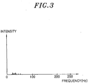
- An example of the background spectrum is shown in Fig. 3 .
- the determining unit 53 stores in advance therein a reference spectrum, which is used in determining whether or not there is a moving object in the detection range. That is, with respect to each frequency included in the difference spectrum and the reference spectrum, the determining unit 53 compares the intensity of each frequency in the difference spectrum with the intensity of a corresponding frequency in the reference spectrum. Specifically, in comparing the intensities, when the intensities of, e.g., five frequencies in the difference spectrum are higher than those in the reference spectrum, the determining unit 53 determines that there is a moving object in the detection range.
- the determining unit 53 determines that there is no moving object in the detection range. In other words, the determining unit 53 determines that there exists no human body in the detection range.
- five frequencies are used as a reference in determining the existence of a moving object, but the present invention is not limited thereto. For example, six or seven or more frequencies may be used as a reference.
- the determining unit 53 determines whether or not the moving object is a human body through a spectrum analysis using a frequency having the highest intensity (hereinafter, referred to as 'first peak frequency') in the difference spectrum. Specifically, the determining unit 53 determines whether or not one of the first peak frequency and a frequency having the second highest intensity (hereinafter, referred to as a 'second peak frequency') is an integer multiple of the other. In other words, the determining unit 53 determines whether or not a value obtained by dividing the first peak frequency by the second peak frequency is N or 1/N.
- N is an integer that is equal to or greater than 2.
- the determining unit 53 determines that the moving object is not a human body and that there is no human body in the detection range. Accordingly, it is possible to avoid an erroneous detection caused by regarding as a human body a periodically operating moving object, such as an air blower, or an erroneous detection resulting from periodical electronic noises generated by an electric device such as a discharge lamp lighting device or the like.
- Fig. 1B shows an example of the difference spectrum used in determining that a moving object is not a human body based on the foregoing operation.
- the first peak frequency is 120 Hz
- the second peak frequency is 60 Hz
- the first peak frequency is an integer multiple (double) of the second peak frequency.
- the determining unit 53 calculates a sum (or an integral) of the intensities of the frequencies in each of frequency bands of the same width in the low frequency side and the high frequency side with respect to the first peak frequency in the difference spectrum.
- the width of the frequency band in which the summation (or integration) is executed is X
- a summation (or integration) range of the low frequency side is fm-X to fm
- an integration range of the high frequency side is fm to fm+X.
- the width X of the frequency band is as large as possible. For example, if the difference spectrum ranges from 1 Hz to 500 Hz and when the first peak frequency fm is lower than 250 Hz, the width X of the frequency band becomes equal to the first peak frequency fm, so that 1 Hz is included in the summation range of the low frequency side.
- the width X of the frequency band becomes 500-fm obtained by subtracting the first peak frequency fm from 500 Hz, so that 500 Hz is included in the summation range of the high frequency side.
- the determining unit 53 determines that the moving object is not a human body and that there is no human body in the detection range.
- the difference spectrum includes components of relatively high frequencies (e.g., 160 Hz) generated by movement of a whole part of the human body and components of relatively low frequencies from, e.g., several tens to one hundred and several tens of hertz generated by movement of hands or feet thereof.
- relatively high frequencies e.g. 160 Hz
- relatively low frequencies from, e.g., several tens to one hundred and several tens of hertz generated by movement of hands or feet thereof.
- the intensity the component generated by the movement of the whole part of the human body become relatively high and, thus, the first peak frequency is included in the components of the relatively high frequencies. Accordingly, the value of the sum becomes higher in the low frequency side of the first peak frequency than in the high frequency side thereof.
- Fig. 1C shows an example of the difference spectrum used in determining that a moving object is not a human body by the foregoing operation.
- the first peak frequency is about 10 Hz.
- the determining unit 53 determines that the moving object is a human body and that there is a human body in the detection range.
- the conditions of the comparison between the difference spectrum and the reference spectrum, the comparison between the first peak frequency and the second peak frequency, and the comparison between the sums of the low frequency side and the high frequency side of the first peak frequency are all met, it is determined that there is a human body in the detection range, and when one or more of the conditions are not met, it is determined that there is no human body in the detection range.
- Fig. 1A shows an example of the difference spectrum used in determining that there is a human body in the detection range.
- the determining unit 53 determines that there is a human body in the detection range, the determining unit 53 outputs a signal (hereinafter, referred to as 'detection signal') indicating that a human body has been detected.
- the detection signal is, for example, a voltage signal.
- the detection signal is inputted to, e.g., the light source driving unit 7 for turning on an electrical light source 6 based on the determination result of the determining unit 53.
- the light source 6 a known light source such as a light emitting diode (LED), a fluorescent lamp, or the like may be used.
- a known DC power circuit may be used as the light source driving unit 7.
- a fluorescent lamp is used as the light source 6, a known electronic ballast may be used as the light source driving unit 7.
- the light source driving unit 7 turns on the light source 6 with a rated power until a certain control delay time lapses after it is determined by the determining unit 53 that a human body exists in the detection range (i.e., after a detection signal is inputted). Then, when a state in which it is determined by the determining unit 53 that there is no human body in the detection range (i.e., a state in which a detection signal is not inputted) continues for the control delay time, the light source driving unit 7 turns off the light source 6 or reduces a power outputted to the light source 6. 12
- the doppler sensor 1 and the light source driving unit 7 may be respectively provided in separate units that transmit and receive signals to and from each other, or may be provided in a single illumination device.
Landscapes
- Engineering & Computer Science (AREA)
- Radar, Positioning & Navigation (AREA)
- Remote Sensing (AREA)
- Computer Networks & Wireless Communication (AREA)
- Physics & Mathematics (AREA)
- General Physics & Mathematics (AREA)
- Radar Systems Or Details Thereof (AREA)
- Circuit Arrangement For Electric Light Sources In General (AREA)
Abstract
Description
- The present invention relates to a doppler sensor and an illumination device including same.
- A doppler sensor for detecting a human body has been provided in the prior art (see, e.g., Japanese Patent Application Publication No.
2010-191857 - Another sensor for detecting a human body is, for example, a thermal sensor for detecting thermic rays radiated from a human body. However, in comparison to this thermal sensor, the doppler sensor has the advantage of detecting a human body located at a long distance. Accordingly, the doppler sensor is more adequate for the case of being fixed to a high ceiling in a building.
- The doppler sensor as described above is used in an illumination device which turns on and off a light source depending on a detection of a human body by the doppler sensor. In comparison to the case when the light source is manually turned on and off, such an illumination device makes it possible to reduce unnecessary power consumption caused when a user forgets manipulation of turning off the light source.
- In the prior art doppler sensor, the sum of intensities of a certain number of frequencies in a doppler signal is compared with a certain threshold value and, when the sum is higher than the threshold value, it is determined that a human body exists.
- However, it happens that, even with moving objects, other than a human body, the sum can be higher than the threshold value, causing erroneous detection.
- In view of the above, the present invention provides a doppler sensor capable of preventing erroneous detection and an illumination device including such a doppler sensor.
- In accordance with an aspect of the present invention, there is provided a doppler sensor including a doppler signal generation unit for transmitting an electric wave to a detection range and receiving electric waves from a detection range, and generating a doppler signal based on a transmission signal used in transmitting the electric wave and a reception signal obtained from the received electric waves; and a determining unit for determining whether or not there exists a human body in the detection range through a spectrum analysis using a first peak frequency, which is a frequency having the highest intensity in a difference spectrum obtained by subtracting a background spectrum from the spectrum of the doppler signal.
- In the spectrum analysis, the determining unit may calculate sums of intensities over frequency bands of a same width in a low frequency side and a high frequency side with respect to the first peak frequency, and determines that there is no human body in the detection range when a sum in the low frequency side is less than that in the high frequency side.
- In the spectrum analysis, the determining unit may determine that there is no human body in the detection range when one of the first peak frequency and a second peak frequency having the second highest intensity in the difference spectrum is an integral multiple of the other.
- In accordance with another aspect of the present invention, there is provided an illumination device including the doppler sensor; and a light source driving unit for turning on an electric light source based on a determination result from the determining unit.
- In accordance with an embodiment of the present invention, it is determined whether a human body exists in a detection range through a spectrum analysis using a first peak frequency, which is a frequency having the highest intensity in the difference spectrum obtained by subtracting a background spectrum from the spectrum of the doppler signal. Accordingly, it is possible to suppress an erroneous detection in comparison to a case where the foregoing spectrum analysis is not executed.
- The objects and features of the present invention will become apparent from the following description of embodiments, given in conjunction with the accompanying drawings, in which:
-
Figs. 1A to 1C show examples of difference spectrums obtained in an embodiment of the present invention, in whichFig. 1A shows an example of determining that a human body exists in a detection range, andFigs. 1B and 1C show examples of determining that no human body exists in the detection range, respectively; -
Fig. 2 is a block diagram showing an illumination device in accordance with the present embodiment; and -
Fig. 3 is an explanatory view showing an example of a background spectrum in accordance with the present embodiment. - An embodiment of the present invention will be described with reference to the accompanying drawings which form a part hereof.
- As shown in
Fig. 2 , anillumination device 10 of the present embodiment includes a doppler sensor 1 and a light source driving unit 7. The doppler sensor 1 includes atransceiver unit 2 for transmitting an electric wave and receiving electric waves to and from a certain detection range; a filter unit 3 for extracting a doppler signal from an output from thetransceiver unit 2; an amplifyingunit 4 for amplifying an output from the filter unit 3; an A/D converting unit 51 for performing A/D conversion on an output from the amplifyingunit 4; a fast Fourier transform (FFT) unit 52 for performing FFT on an output from the A/D converting unit 51 to generate an intensity distribution of frequencies (spectrum) in the doppler signal; and a determiningunit 53 for determining whether or not there exists a human body within the detection range based on an output from the FFT unit 52. That is, thetransceiver unit 2 and the filter unit 3 constitute a doppler signal generation unit. - The A/
D converting unit 51, the FFT unit 52, and the determiningunit 53 are integrated in a one-chip microcomputer 5. A spectrum is, e.g., periodically inputted to the determiningunit 53 from the FFT unit 52. - The
transceiver unit 2 includes anoscillator 21 which generates a transmission signal of a certain frequency; atransmitting antenna 22 for transmitting to a detection range a transmission wave, which is an electric wave to which the transmission signal is converted; areceiving antenna 23 for receiving reflection waves, which are the electric waves generated by the reflection of the transmission wave from the transmittingantenna 22, reflected from the detection range and converting the reflection waves into a reception signal; and amixer 24 for mixing the transmission signal outputted from theoscillator 21 and the reception signal outputted from thereceiving antenna 23 and outputting the thus-obtained mixture signal to the filter unit 3. Thetransceiver unit 2 as described above can be realized by a known technique, so a detailed illustration and description thereof will be omitted. Also, instead of separately providing the transmittingantenna 22 and thereceiving antenna 23 as mentioned above, a single antenna may perform such transmission and reception by using, for example, a known circulator. - Here, when a frequency of the electric wave transmitted by the
transceiver unit 2, the speed of light, and a relative velocity between a moving object and thetransceiver unit 2 are respectively given as f0, c and v m/s, a doppler frequency corresponding to a moving object is obtained as 2×v×f0/c. For example, let's consider a case where the frequency of a transmission signal is 24 GHz and if a relative velocity between the moving object and thetransceiver unit 2 is 2m/s or lower, the moving object is determined as a human body. In such a case, an upper limit of the frequencies to be provided by the filter unit 3 is obtained as about 320 (2×2×24×109/(3×108)) Hz by substituting 2 m/s, 24×109 Hz, about 3×10⁸ m/s for v, f0 and c in the above equation. In the present embodiment, however, the upper limit of the frequencies provided by the filter unit 3 is set to be higher than the foregoing value, and the intensity in the doppler signal is provided at every 1 Hz from 1 Hz to 500 Hz in the output from the FFT unit 52, for example. - Hereinafter, an operation of the determining
unit 53 as the features of the present embodiment will be described. The following operation is executed whenever a spectrum of a doppler signal is inputted from the FFT unit 52 to the determiningunit 53. - The determining
unit 53 stores in advance a background spectrum therein, and subtracts the background spectrum from the spectrum of the doppler signal inputted from the FFT unit 52 to thereby obtain a difference spectrum, by which the determiningunit 53 executes determination. Here, the background spectrum is, for example, a spectrum of the doppler signal in a state in which there exists no moving object in the detection range. An example of the background spectrum is shown inFig. 3 . - Further, the determining
unit 53 stores in advance therein a reference spectrum, which is used in determining whether or not there is a moving object in the detection range. That is, with respect to each frequency included in the difference spectrum and the reference spectrum, the determiningunit 53 compares the intensity of each frequency in the difference spectrum with the intensity of a corresponding frequency in the reference spectrum. Specifically, in comparing the intensities, when the intensities of, e.g., five frequencies in the difference spectrum are higher than those in the reference spectrum, the determiningunit 53 determines that there is a moving object in the detection range. - On the other hand, when the number of frequencies whose intensities in the difference spectrum are higher than those in the reference spectrum is less than 5 in the comparison, the determining
unit 53 determines that there is no moving object in the detection range. In other words, the determiningunit 53 determines that there exists no human body in the detection range. In the present embodiment, five frequencies are used as a reference in determining the existence of a moving object, but the present invention is not limited thereto. For example, six or seven or more frequencies may be used as a reference. - In addition, when the determining
unit 53 determines that there is a moving object in the detection range, it then determines whether or not the moving object is a human body through a spectrum analysis using a frequency having the highest intensity (hereinafter, referred to as 'first peak frequency') in the difference spectrum. Specifically, the determiningunit 53 determines whether or not one of the first peak frequency and a frequency having the second highest intensity (hereinafter, referred to as a 'second peak frequency') is an integer multiple of the other. In other words, the determiningunit 53 determines whether or not a value obtained by dividing the first peak frequency by the second peak frequency is N or 1/N. Here, N is an integer that is equal to or greater than 2. - When it is determined that one of the first peak frequency and the second peak frequency is an integer multiple of the other, the determining
unit 53 determines that the moving object is not a human body and that there is no human body in the detection range. Accordingly, it is possible to avoid an erroneous detection caused by regarding as a human body a periodically operating moving object, such as an air blower, or an erroneous detection resulting from periodical electronic noises generated by an electric device such as a discharge lamp lighting device or the like. -
Fig. 1B shows an example of the difference spectrum used in determining that a moving object is not a human body based on the foregoing operation. In the example ofFig. 1B , the first peak frequency is 120 Hz, the second peak frequency is 60 Hz, and the first peak frequency is an integer multiple (double) of the second peak frequency. - Further, when one of the first peak frequency and the second peak frequency is not an integer multiple of the other, the determining
unit 53 calculates a sum (or an integral) of the intensities of the frequencies in each of frequency bands of the same width in the low frequency side and the high frequency side with respect to the first peak frequency in the difference spectrum. - If it is assumed that the first peak frequency is fm and the width of the frequency band in which the summation (or integration) is executed is X, a summation (or integration) range of the low frequency side is fm-X to fm, and an integration range of the high frequency side is fm to fm+X. Preferably, the width X of the frequency band is as large as possible. For example, if the difference spectrum ranges from 1 Hz to 500 Hz and when the first peak frequency fm is lower than 250 Hz, the width X of the frequency band becomes equal to the first peak frequency fm, so that 1 Hz is included in the summation range of the low frequency side. On the other hand, when the first peak frequency fm is higher than 250 Hz, the width X of the frequency band becomes 500-fm obtained by subtracting the first peak frequency fm from 500 Hz, so that 500 Hz is included in the summation range of the high frequency side.
- Then, when the value of the sum in the low frequency side of the first peak frequency is less than that in the high frequency side thereof, the determining
unit 53 determines that the moving object is not a human body and that there is no human body in the detection range. - Here, when the moving object is a human body, the difference spectrum includes components of relatively high frequencies (e.g., 160 Hz) generated by movement of a whole part of the human body and components of relatively low frequencies from, e.g., several tens to one hundred and several tens of hertz generated by movement of hands or feet thereof. As for the intensity, the component generated by the movement of the whole part of the human body become relatively high and, thus, the first peak frequency is included in the components of the relatively high frequencies. Accordingly, the value of the sum becomes higher in the low frequency side of the first peak frequency than in the high frequency side thereof.
- As for, e.g., raindrops, however, the value of the sum tends to be lower in the low frequency side of the first peak frequency than in the high frequency side thereof. In other words, through the foregoing operation, it is possible to prevent raindrops from being erroneously detected as a human body.
Fig. 1C shows an example of the difference spectrum used in determining that a moving object is not a human body by the foregoing operation. In the example ofFig. 1C , the first peak frequency is about 10 Hz. - On the other hand, when the value of the sum is greater in the low frequency side than in the high frequency side, the determining
unit 53 determines that the moving object is a human body and that there is a human body in the detection range. In brief, in the present embodiment, only when the conditions of the comparison between the difference spectrum and the reference spectrum, the comparison between the first peak frequency and the second peak frequency, and the comparison between the sums of the low frequency side and the high frequency side of the first peak frequency are all met, it is determined that there is a human body in the detection range, and when one or more of the conditions are not met, it is determined that there is no human body in the detection range.Fig. 1A shows an example of the difference spectrum used in determining that there is a human body in the detection range. - Further, when the determining
unit 53 determines that there is a human body in the detection range, the determiningunit 53 outputs a signal (hereinafter, referred to as 'detection signal') indicating that a human body has been detected. The detection signal is, for example, a voltage signal. - The detection signal is inputted to, e.g., the light source driving unit 7 for turning on an electrical
light source 6 based on the determination result of the determiningunit 53. As thelight source 6, a known light source such as a light emitting diode (LED), a fluorescent lamp, or the like may be used. When an LED is used as thelight source 6, a known DC power circuit may be used as the light source driving unit 7. When a fluorescent lamp is used as thelight source 6, a known electronic ballast may be used as the light source driving unit 7. - Further, as for an operation of the light source driving unit 7, the following may be made. For example, the light source driving unit 7 turns on the
light source 6 with a rated power until a certain control delay time lapses after it is determined by the determiningunit 53 that a human body exists in the detection range (i.e., after a detection signal is inputted). Then, when a state in which it is determined by the determiningunit 53 that there is no human body in the detection range (i.e., a state in which a detection signal is not inputted) continues for the control delay time, the light source driving unit 7 turns off thelight source 6 or reduces a power outputted to thelight source 6. 12 - The doppler sensor 1 and the light source driving unit 7 may be respectively provided in separate units that transmit and receive signals to and from each other, or may be provided in a single illumination device.
- While the invention has been shown and described with respect to the embodiments, it will be understood by those skilled in the art that various changes and modifications may be made without departing from the scope of the invention as defined in the following claims.
Claims (4)
- A doppler sensor comprising:a doppler signal generation unit for transmitting an electric wave to a detection range and receiving electric waves from a detection range, and generating a doppler signal based on a transmission signal used in transmitting the electric wave and a reception signal obtained from the received electric waves; anda determining unit for determining whether or not there exists a human body in the detection range through a spectrum analysis using a first peak frequency, which is a frequency having the highest intensity in a difference spectrum obtained by subtracting a background spectrum from the spectrum of the doppler signal.
- The doppler sensor of claim 1, wherein, in the spectrum analysis, the determining unit calculates sums of intensities over frequency bands of a same width in a low frequency side and a high frequency side with respect to the first peak frequency, and determines that there is no human body in the detection range when a sum in the low frequency side is less than that in the high frequency side.
- The doppler sensor of claim 1 or 2, wherein, in the spectrum analysis, the determining unit determines that there is no human body in the detection range when one of the first peak frequency and a second peak frequency having the second highest intensity in the difference spectrum is an integral multiple of the other.
- An illumination device comprising:the doppler sensor of any one of claims 1 to 3; anda light source driving unit for turning on an electric light source based on a determination result from the determining unit.
Applications Claiming Priority (1)
| Application Number | Priority Date | Filing Date | Title |
|---|---|---|---|
| JP2011030026A JP2012168048A (en) | 2011-02-15 | 2011-02-15 | Doppler sensor and lighting fixture using the doppler sensor |
Publications (2)
| Publication Number | Publication Date |
|---|---|
| EP2490041A2 true EP2490041A2 (en) | 2012-08-22 |
| EP2490041A3 EP2490041A3 (en) | 2012-11-07 |
Family
ID=45655002
Family Applications (1)
| Application Number | Title | Priority Date | Filing Date |
|---|---|---|---|
| EP12000952A Withdrawn EP2490041A3 (en) | 2011-02-15 | 2012-02-14 | Doppler sensor and illumination device including same |
Country Status (4)
| Country | Link |
|---|---|
| US (1) | US9207308B2 (en) |
| EP (1) | EP2490041A3 (en) |
| JP (1) | JP2012168048A (en) |
| CN (1) | CN102636781B (en) |
Families Citing this family (14)
| Publication number | Priority date | Publication date | Assignee | Title |
|---|---|---|---|---|
| JP5713322B2 (en) * | 2012-11-21 | 2015-05-07 | サンデン株式会社 | Sensor unit, vending machine, and raindrop detection and identification method using human sensor |
| EP3049995B1 (en) * | 2013-09-25 | 2018-03-21 | Philips Lighting Holding B.V. | Detection system and method and space control system using such a detection system |
| JP6005101B2 (en) * | 2014-05-08 | 2016-10-12 | 株式会社光波 | Moving object detection device and vending machine |
| CN105277991B (en) * | 2014-05-30 | 2018-11-02 | 南充鑫源通讯技术有限公司 | There are detection method and device |
| CN106707348A (en) * | 2016-12-09 | 2017-05-24 | 济南赛英立德电子科技有限公司 | Microwave Doppler static human body detection method based on time frequency analysis and detector |
| JP7150292B2 (en) * | 2017-03-31 | 2022-10-11 | 慶應義塾 | Action recognition system and action recognition method |
| CN107422318A (en) * | 2017-05-27 | 2017-12-01 | 南京理工大学 | A kind of take sensor and its detection method based on Doppler technology |
| JP7045648B2 (en) * | 2017-12-20 | 2022-04-01 | いすゞ自動車株式会社 | Vehicle object detector |
| US10948581B2 (en) * | 2018-05-30 | 2021-03-16 | Richwave Technology Corp. | Methods and apparatus for detecting presence of an object in an environment |
| CN109031220A (en) * | 2018-07-23 | 2018-12-18 | 惠州市华阳光电技术有限公司 | A kind of Radar cross-section redaction filtering method and its circuit |
| CN108983194B (en) * | 2018-07-31 | 2020-11-13 | 安徽四创电子股份有限公司 | Target extraction and condensation method based on ground monitoring radar system |
| JP7331085B2 (en) * | 2018-08-14 | 2023-08-22 | シグニファイ ホールディング ビー ヴィ | MICROWAVE SENSOR DEVICE, SENSING METHOD, AND LIGHTING SYSTEM USING SENSOR DEVICE |
| US11922792B2 (en) | 2019-02-22 | 2024-03-05 | Signify Holding B.V. | Luminaire, and a corresponding method |
| CN113724284A (en) * | 2021-09-03 | 2021-11-30 | 四川智胜慧旅科技有限公司 | Position locking device, mountain type scenic spot search and rescue system and search and rescue method |
Citations (1)
| Publication number | Priority date | Publication date | Assignee | Title |
|---|---|---|---|---|
| JP2010191857A (en) | 2009-02-20 | 2010-09-02 | Ibaraki Univ | Sensor device |
Family Cites Families (13)
| Publication number | Priority date | Publication date | Assignee | Title |
|---|---|---|---|---|
| US3760400A (en) * | 1972-02-10 | 1973-09-18 | Aerospace Res | Intrusion detection system employing quadrature sampling |
| US4008474A (en) * | 1975-06-18 | 1977-02-15 | The United States Of America As Represented By The Secretary Of The Army | Doppler radar for distinguishing between approaching and receding targets and having increased frequency response |
| US4400700A (en) * | 1981-06-08 | 1983-08-23 | The United States Of America As Represented By The Secretary Of The Army | Doppler frequency analysis of radar signals |
| US5150099A (en) * | 1990-07-19 | 1992-09-22 | Lienau Richard M | Home security system and methodology for implementing the same |
| JP2737570B2 (en) * | 1992-10-07 | 1998-04-08 | 三菱電機株式会社 | Synthetic aperture radar device |
| DE9400950U1 (en) * | 1994-01-20 | 1995-08-24 | Selectronic Gesellschaft für Sicherheitstechnik und Sonderelektronik mbH, 14542 Werder | Device for detecting living bodies and their use |
| FR2745093B1 (en) * | 1996-02-21 | 1998-04-24 | Legrand Sa | METHOD AND DEVICE FOR DETECTING THE PRESENCE OF A LIVING BEING OF A PARTICULAR SPECIES IN A SPACE MONITORED BY A DOPPLER SENSOR |
| US6307475B1 (en) * | 1999-02-26 | 2001-10-23 | Eric D. Kelley | Location method and system for detecting movement within a building |
| JP4120692B2 (en) * | 2004-05-11 | 2008-07-16 | 株式会社村田製作所 | Radar |
| JP2008224528A (en) | 2007-03-14 | 2008-09-25 | Yamagata Chinoo:Kk | Human body detection device |
| JP4292586B1 (en) * | 2007-12-21 | 2009-07-08 | Toto株式会社 | Water discharge device |
| JP2010176911A (en) | 2009-01-27 | 2010-08-12 | Panasonic Electric Works Co Ltd | Illumination control system |
| US7924212B2 (en) * | 2009-08-10 | 2011-04-12 | Robert Bosch Gmbh | Method for human only activity detection based on radar signals |
-
2011
- 2011-02-15 JP JP2011030026A patent/JP2012168048A/en not_active Withdrawn
-
2012
- 2012-02-13 US US13/371,730 patent/US9207308B2/en not_active Expired - Fee Related
- 2012-02-14 EP EP12000952A patent/EP2490041A3/en not_active Withdrawn
- 2012-02-14 CN CN201210033101.XA patent/CN102636781B/en not_active Expired - Fee Related
Patent Citations (1)
| Publication number | Priority date | Publication date | Assignee | Title |
|---|---|---|---|---|
| JP2010191857A (en) | 2009-02-20 | 2010-09-02 | Ibaraki Univ | Sensor device |
Non-Patent Citations (1)
| Title |
|---|
| CHANGZHI LI ET AL: "Accurate Doppler Radar Noncontact Vital Sign Detection Using the RELAX Algorithm", IEEE TRANSACTIONS ON INSTRUMENTATION AND MEASUREMENT, IEEE SERVICE CENTER, PISCATAWAY, NJ, US, vol. 59, no. 3, 1 March 2010 (2010-03-01), pages 687 - 695, XP011295815, ISSN: 0018-9456 * |
Also Published As
| Publication number | Publication date |
|---|---|
| CN102636781B (en) | 2015-08-26 |
| JP2012168048A (en) | 2012-09-06 |
| CN102636781A (en) | 2012-08-15 |
| US9207308B2 (en) | 2015-12-08 |
| EP2490041A3 (en) | 2012-11-07 |
| US20120206288A1 (en) | 2012-08-16 |
Similar Documents
| Publication | Publication Date | Title |
|---|---|---|
| US9207308B2 (en) | Doppler sensor and illumination device including same | |
| CN108652601B (en) | Sleep monitoring method and device based on frequency modulation continuous wave millimeter wave radar and radar system | |
| JP5377689B2 (en) | LED lighting fixture with built-in standing wave radar | |
| US9618530B2 (en) | Laser radar device | |
| JP5317004B1 (en) | Installation sensor | |
| CN1894595A (en) | Radar | |
| JP6975923B2 (en) | lighting equipment | |
| Di Mattia et al. | A feasibility study of a compact radar system for autonomous walking of blind people | |
| EP2180248A1 (en) | Illumination apparatus | |
| US10481252B2 (en) | Sensor device and lighting device | |
| KR20160054911A (en) | Light controlling system using radar and method for same | |
| EP2834663A1 (en) | Aid device for blind people | |
| EP2458272B1 (en) | Illumination device including doppler sensor | |
| WO2023063093A1 (en) | Radar device and interference countermeasure detection method for radar device | |
| RU2287841C1 (en) | Doppler radio-wave annunciator for intruder alarm | |
| KR200457961Y1 (en) | Microwave Motion Sensor Module with Differential Intermediate Frequency Signal Output | |
| JP2012047493A (en) | Illumination instrument with doppler sensor | |
| JP5543900B2 (en) | Doppler sensor and lighting device using the doppler sensor | |
| JP5222190B2 (en) | Doppler sensor | |
| RU113590U1 (en) | MOVING OBJECT DETECTION DEVICE | |
| JP2012113904A (en) | Lighting fixture with doppler sensor | |
| RU2572547C2 (en) | Photoplethysmograph | |
| JP2012112741A (en) | Lighting fixture with doppler sensor | |
| RU2008121306A (en) | INFRARED THREE-SPECTRAL FLAME DETECTOR | |
| JPH1164512A (en) | Method and device for detecting moving body |
Legal Events
| Date | Code | Title | Description |
|---|---|---|---|
| PUAI | Public reference made under article 153(3) epc to a published international application that has entered the european phase |
Free format text: ORIGINAL CODE: 0009012 |
|
| AK | Designated contracting states |
Kind code of ref document: A2 Designated state(s): AL AT BE BG CH CY CZ DE DK EE ES FI FR GB GR HR HU IE IS IT LI LT LU LV MC MK MT NL NO PL PT RO RS SE SI SK SM TR |
|
| AX | Request for extension of the european patent |
Extension state: BA ME |
|
| PUAL | Search report despatched |
Free format text: ORIGINAL CODE: 0009013 |
|
| AK | Designated contracting states |
Kind code of ref document: A3 Designated state(s): AL AT BE BG CH CY CZ DE DK EE ES FI FR GB GR HR HU IE IS IT LI LT LU LV MC MK MT NL NO PL PT RO RS SE SI SK SM TR |
|
| AX | Request for extension of the european patent |
Extension state: BA ME |
|
| RIC1 | Information provided on ipc code assigned before grant |
Ipc: G01S 13/56 20060101AFI20120928BHEP Ipc: G01S 13/50 20060101ALI20120928BHEP Ipc: G01S 7/41 20060101ALI20120928BHEP Ipc: G01S 17/02 20060101ALI20120928BHEP |
|
| 17P | Request for examination filed |
Effective date: 20130507 |
|
| RBV | Designated contracting states (corrected) |
Designated state(s): AL AT BE BG CH CY CZ DE DK EE ES FI FR GB GR HR HU IE IS IT LI LT LU LV MC MK MT NL NO PL PT RO RS SE SI SK SM TR |
|
| RAP1 | Party data changed (applicant data changed or rights of an application transferred) |
Owner name: PANASONIC INTELLECTUAL PROPERTY MANAGEMENT CO., LT |
|
| 17Q | First examination report despatched |
Effective date: 20160201 |
|
| RIC1 | Information provided on ipc code assigned before grant |
Ipc: G01S 13/75 20060101ALI20190208BHEP Ipc: G01S 7/41 20060101ALI20190208BHEP Ipc: G01S 13/56 20060101AFI20190208BHEP Ipc: H05B 37/02 20060101ALI20190208BHEP Ipc: G01S 17/02 20060101ALI20190208BHEP Ipc: H04B 1/59 20060101ALI20190208BHEP |
|
| GRAP | Despatch of communication of intention to grant a patent |
Free format text: ORIGINAL CODE: EPIDOSNIGR1 |
|
| INTG | Intention to grant announced |
Effective date: 20190410 |
|
| STAA | Information on the status of an ep patent application or granted ep patent |
Free format text: STATUS: THE APPLICATION IS DEEMED TO BE WITHDRAWN |
|
| 18D | Application deemed to be withdrawn |
Effective date: 20190821 |