EP2489956B2 - Kühleinrichtung eines elektrischen, sich erwärmenden Bauelements - Google Patents
Kühleinrichtung eines elektrischen, sich erwärmenden Bauelements Download PDFInfo
- Publication number
- EP2489956B2 EP2489956B2 EP11155224.6A EP11155224A EP2489956B2 EP 2489956 B2 EP2489956 B2 EP 2489956B2 EP 11155224 A EP11155224 A EP 11155224A EP 2489956 B2 EP2489956 B2 EP 2489956B2
- Authority
- EP
- European Patent Office
- Prior art keywords
- clamping
- cooling
- cooling device
- circuit board
- connection
- Prior art date
- Legal status (The legal status is an assumption and is not a legal conclusion. Google has not performed a legal analysis and makes no representation as to the accuracy of the status listed.)
- Active
Links
Images
Classifications
-
- H—ELECTRICITY
- H10—SEMICONDUCTOR DEVICES; ELECTRIC SOLID-STATE DEVICES NOT OTHERWISE PROVIDED FOR
- H10W—GENERIC PACKAGES, INTERCONNECTIONS, CONNECTORS OR OTHER CONSTRUCTIONAL DETAILS OF DEVICES COVERED BY CLASS H10
- H10W40/00—Arrangements for thermal protection or thermal control
- H10W40/60—Securing means for detachable heating or cooling arrangements, e.g. clamps
- H10W40/611—Bolts or screws
-
- F—MECHANICAL ENGINEERING; LIGHTING; HEATING; WEAPONS; BLASTING
- F24—HEATING; RANGES; VENTILATING
- F24H—FLUID HEATERS, e.g. WATER OR AIR HEATERS, HAVING HEAT-GENERATING MEANS, e.g. HEAT PUMPS, IN GENERAL
- F24H1/00—Water heaters, e.g. boilers, continuous-flow heaters or water-storage heaters
- F24H1/10—Continuous-flow heaters, i.e. heaters in which heat is generated only while the water is flowing, e.g. with direct contact of the water with the heating medium
- F24H1/12—Continuous-flow heaters, i.e. heaters in which heat is generated only while the water is flowing, e.g. with direct contact of the water with the heating medium in which the water is kept separate from the heating medium
- F24H1/121—Continuous-flow heaters, i.e. heaters in which heat is generated only while the water is flowing, e.g. with direct contact of the water with the heating medium in which the water is kept separate from the heating medium using electric energy supply
-
- F—MECHANICAL ENGINEERING; LIGHTING; HEATING; WEAPONS; BLASTING
- F24—HEATING; RANGES; VENTILATING
- F24H—FLUID HEATERS, e.g. WATER OR AIR HEATERS, HAVING HEAT-GENERATING MEANS, e.g. HEAT PUMPS, IN GENERAL
- F24H9/00—Details
- F24H9/20—Arrangement or mounting of control or safety devices
- F24H9/2007—Arrangement or mounting of control or safety devices for water heaters
- F24H9/2014—Arrangement or mounting of control or safety devices for water heaters using electrical energy supply
- F24H9/2028—Continuous-flow heaters
Definitions
- the invention relates to a cooling device of an electronic, warming component, comprising the electronic component having a heat conducting surface for heat dissipation and electrical connection pins, an electrical circuit board having two opposing surface sides with connection points to which the electrical connection pins are connected, a thermal cooling element with a cooling surface , which rests against the heat-conducting surface, and a bearing body on which the circuit board is mounted.
- the electronic component is in particular an electronic power switching element with a semiconductor layer structure, e.g. in the form of thyristors, power transistors or triacs. It has pin-shaped connection pins, by means of which it is usually soldered onto a printed circuit board, for example in the form of a printed circuit card, circuit board or printed circuit.
- a heat-emitting heat-conducting surface of the component must be pressed against a heat-dissipating cooling surface in order to limit heating during operation of the component and thus ensure its function.
- Numerous different cooling devices are known.
- a cooling device in connection with semiconductor elements which are in thermal contact with a thermally conductive base of a housing (bearing body).
- a clamping device of the cooling device provided for each semiconductor element comprises a clamping assembly in which a heat-conducting layer, a metal contact strip, a heating semiconductor element, a metal pressure piece, a supply electrode and an insulating piece are located one after the other, these parts being clamped between a clamping surface of the thermally conductive housing bottom and a clamping surface of a spring arranged on the housing are inserted.
- the contact strip and the feed electrode are connected to electrical leads that are led out of the housing for connection, for example, to an electrical circuit board that can only be arranged outside the housing and the row of clamped parts.
- the housing forms the housing, which accommodates a plurality of said semiconductor elements, of an independent semiconductor component.
- a frequently used arrangement for cooling consists in that a circuit breaker is aligned upright with its heat-conducting surface on a circuit board and the heat-conducting surface is placed laterally against a cooling medium, for example copper or brass parts forming cooling surfaces.
- a cooling medium for example copper or brass parts forming cooling surfaces.
- circuit breakers of power electronics are attached directly to a water pipe for cooling ( DE 20 2004 012 263 , Fig. 5).
- the heat dissipation remains unsatisfactory.
- a planar system of adjacent thermal surfaces can only be produced to a limited extent.
- the desired planar system is particularly impaired by the fact that, in particular in series production, surface or contour tolerances of the circuit breaker and / or other components involved in the associated assembly, especially if the components are obtained from different manufacturers, lead to maladjustment that hinders thermal heat transfer.
- Clamping means that are attached directly to the cooling element and the structural element and generate clamping force are usually used.
- connection pins of the electronic circuit breakers or similar components have a relatively short length and can withstand mechanical stress only to a very limited extent. Mechanical stress in conventional clamp and / or screw connections sometimes means that soldered connections of connection pins at the connection points are defective from the start or come loose later. The component tolerances mentioned favor such disadvantageous effects.
- the invention is based on the objectives of improving the cooling device with regard to reliably effective cooling, compact design and size, the elimination of mechanical influences, in particular due to physical tolerance deviations of identical electronic components, and ease of assembly.
- the clamping surfaces provided on the bearing body form one or more defined clamping surface pairs between each of which is clamped in a clamp assembly in which at least one electronic component is pressed onto the associated cooling element with the heat-conducting surface of the component resting flat or on the surface of the cooling element.
- the clamping surfaces defined in their spatial relation to one another determine the position of the clamping connection.
- the circuit board extends through between the clamping surfaces of each clamping surface pair, the position of the electronic component being defined in relation to the clamping plate. Clamping / tensioning forces on the clamp assembly are not transmitted to the connection pins or connection points via the assembly or the circuit board.
- the measures according to the invention mean that component or contour tolerances and also dimensional differences of the electronic components can be met without impairing the cooling connection. Clamping forces can be applied and adjusted in a defined and reproducible manner.
- a particularly preferred design consists in that the clamp assembly is formed by the cooling element, a clamp holder and, in a clamped arrangement between the cooling element and the clamp holder, at least one electronic component.
- the clamp holder forms an element on which the electronic component is located in a form-fitting seat on its side facing the first clamping surface.
- the head side of the clamp assembly assigned to the first clamp surface is formed by the clamp holder.
- the design can then be expediently such that the clamp holder on the head side of the clamp assembly has a head surface facing the printed circuit board, on which at least one protrusion protruding from the head surface, penetrating the passage recess and located in a clamping position on the first clamping surface is formed.
- the projection and the penetration recess can be dimensioned in a form-fitting adaptation to one another in such a way that an adjustment aid for attaching the clamp holder is thereby formed.
- the clamp holder has a shaped edge assigned to the connection pins, on which the connection pins are bent with the formation of a defined buckling length and alignment with the connection points of the circuit board.
- Recesses can be formed on the molded edge of the clamp holder which receive the connection pins in order to counteract creeping currents between the connection pins to a particular degree.
- the clamp holder which is advantageously made of plastic, forms a spacer that connects the electronic component to the first Clamping surface at a defined distance. At the same time, it forms an adjustment and assembly aid for attaching the electronic component when its connection pins, as usual, are soldered to the connection points.
- the clamp holder is advantageously held captive between the circuit board and the connection pins fastened to the connection points of the circuit boards. It can be expedient for at least two electronic components to be located in a clamp assembly with one and the same clamp holder.
- a particularly space-saving arrangement consists in that the circuit board has a recess through which at least one connecting element extends, which connects the first clamping surface to the bearing body. At least one connecting element is expediently part of a screw connection.
- the screw connection consists particularly advantageously of a base freely extending through said recess of the circuit board and an associated clamping screw screwed into it. Instead of a screw connection, other connections can be provided for assembly or for fixing the clamping surface on the bearing body.
- the first clamping surface is advantageous, i. H. at least one first clamping surface or each first clamping surface is formed by a clamping arm or a part acting as a clamping arm.
- a plate element or the like is preferably mounted on the bearing body, in particular by means of a screw connection. It is also advantageous that several first clamping surfaces can be formed by at least two clamping arms, for example by a double arm formed by means of a clamping plate, which are arranged and fastened to the bearing body by means of a common connection.
- any body suitable for thermal heat dissipation for example made of copper, brass, ceramic material or the like, can be provided as a cooling element, which, for example by means of fins or ribs, gives off heat to a cooling medium or another heat sink.
- the design according to the invention consists in that the cooling element has a cooling foot which is designed to give off heat to the liquid and can be freely immersed in the liquid, as well as a support element for clamping against the second clamping surface.
- Such a cooling element can be used in connection with further design measures to further improve the cooling heat transfer.
- the invention provides that the bearing body has a fluid channel set up to guide fluid under pressure and comprises a shaft opening into the liquid channel which receives the cooling foot in the seat sealed against the passage of liquid, a foot end of the cooling foot designed to give off heat protruding into the liquid channel.
- the first clamping surface can expediently be a clamping arm that acts in particular in a resilient manner.
- the design can be such that the cooling element is held freely or evasively in the clamping contact position on the second clamping surface for the transmission of additional clamping force, directed against the clamping force or spring-elastic restoring force acting by means of the first clamping surface.
- the electronic component which is located in the clamping assembly between the first clamping surface and the second clamping surface, is additionally pressed for cooling by means of a pressure force that is exerted on the cooling element via the liquid.
- a cooling arrangement is of particular advantage in an electronically controlled hot water device, namely a water heater with an electrical heating device for heating water flowing through the water heater.
- the heating device has at least one electronic component to be cooled as a power switch, which can be controlled with power electronics to regulate the hot water temperature, and a cooling device for cooling the power switch.
- At least one cooling element of the cooling device is in thermal connection with a heat-conducting surface of the circuit breaker and emits heat to water to be heated by means of the heating device.
- the invention provides that the circuit board is free of mechanical attachment to the bearing body in the area of the electronic component.
- the bearing body has at least one guide element in the vicinity or in the area of the electronic component, which provides a guide perpendicular to the surface sides of the printed circuit board for at least substantially surface-parallel guide positioning of the PCB forms.
- the cooling device 1 comprises an electronic component 2, in the exemplary embodiment a triac circuit breaker, an electrical circuit board 6, thermal cooling elements 3 and a bearing body 5.
- Components of a clamping device 7 are first clamping surfaces 71, formed by a clamping plate 70 and second clamping surfaces 72 as well as a Screw connection 73, by means of which the clamping plate 70 is arranged on the bearing body 5.
- the clamping device 7 comprises a clamping assembly 8 provided twice. This forms one half of the arrangement of the cooling device 1.
- the clamping assembly 8 is designed in three parts, namely with the cooling element 3 in the form of a T-shaped cooling nipple made of thermally conductive material, the component 2 and one Clamp holder 4.
- the cooling element 3 has a cooling foot 32 with cooling ribs 320 and a support element 33, formed by a head plate, which supports the cooling element 3 within the bearing body 5 against the clamping surfaces 72.
- a planar top surface of the support element 33 forms a cooling surface 31 of the cooling element 3.
- the component 2 has a planar heat-conducting surface 21, with which it rests flat and therefore flat on the cooling surface 31 in the clamping assembly 8.
- the support element 33 of the cooling element 3 forms a foot side of the clamp assembly 8
- the head side of the clamp assembly 8 is formed by the clamp holder 4. It can be seen that in the clamp assembly 8 the component 2 is inserted between the support element 33 and the clamp holder 4.
- the circuit board 6 has two penetration recesses 64, one penetration recess 64 being assigned to the associated clamping assembly 8.
- the clamping surfaces 71, 72 associated with the clamping assembly 8 form a pair of clamping surfaces which produces the clamping assembly 8 in a press fit between these clamping surfaces 71, 72.
- the first clamping surface 71 extends in front of and at least essentially parallel to a first printed circuit board surface side 61 which faces away from the component 2 or the cooling element 3.
- the other second surface side 62 of the printed circuit board 6, which is plane-parallel with the first surface side 61, faces the component 2 or the support element 33 of the cooling element 3 arranged in front of this second surface side 62.
- the second clamping surface 72 extends in front of the second surface side 62 and is at least substantially parallel to it.
- a clamping device with one or more parallel pairs of parallel first and second clamping surfaces is not limited to the exemplary embodiment.
- the head side of the clamping assembly 8 extends with a head part through the penetration recess 64 in order to obtain the arrangement of the clamping assembly 8 between the two clamping surfaces 71, 72.
- the clamp holder 4 forms a top surface 81 of the clamp assembly 8, which almost or positively, but possibly only with a slight force compared to the clamping force of the clamp assembly 8, comes to rest on the second surface side 62.
- clamp assembly 8 with the clamp holder 4 has particular advantages, in general any clamp assembly composed of a cooling element and an electronic component, also in two parts without a clamp holder 4, can be provided.
- the clamp holder 4 is not limited to the design described. If necessary, it can also be made up of several parts. Furthermore, elevations can be formed on the clamping plate 70 or the clamping surfaces 71 or projections can be arranged which, instead of the projections 81, reach through the penetration recesses.
- the second clamping surface 72 is a passive clamping surface such that it forms a fixed abutment for the support element 33 that is incorporated into the bearing body 5.
- the cooling element 3 has a head width B which is smaller than the clear width between two opposing edges 521, which form an enclosure for receiving the T head of the support element 33.
- the space in the bearing body 5 adapted to the cooling foot 32 forms a shaft 52 in which the cooling foot 32 is located in the sealing seat.
- the sealing seat is produced by sealing rings 34 inserted into circumferential grooves on the cooling foot 32.
- the cooling element 3 can be easily mounted before the component 2 and the clamp 4 are attached by inserting the cooling element 3 in a position rotated by 90 ° about its foot axis in relation to the holding position shown and then rotating it into the holding position.
- the two clamping surfaces 71 are identical parts of the clamping plate 70. They form clamping arms 711, 712 which each form a spring-elastic, tension-free clamping element by means of the screw connection 73.
- the printed circuit board 6 has a recess 65 in the middle between the two clamp connection arrangements.
- a protruding dome-like base element 54 of the bearing body 5 engages with an outer receding edge through the recess 65 and has an inner bore of a screw connection 73.
- a head screw 74 engaging the clamping plate 70 with its head neck is screwed into the inner bore.
- a tensioning device is formed with which the tensioning / clamping force can be adjusted in a targeted manner via the resilient plate clamping arms 711, 712 depending on the tightening of the head screw.
- the clamping surfaces 71 act as active clamping surfaces.
- Cooling devices according to the invention can also have second clamping surfaces that can be actively acted upon with clamping force, in addition to active or in combination with passive (fixed) first clamping surfaces.
- a separate clamping means can be assigned to each clamping assembly 8.
- the clamping holder 4 which is preferably formed from plastic, has a cap-like shape with shaped edges 42.
- a seat for the component 2 is formed between the mold edges 42, which seat is such that components 2 with different housing dimensions, in particular those with tolerance deviations, are also formed the design can be included. In particular, the effect of tolerance deviations can be countered by adjusting the clamping force in order to produce a cooling connection that is nevertheless always reliable and stable.
- One shaped edge 42 forms an edge at which the connection pins 22 are bent with a defined kink length and alignment with connection points 63 of the circuit board 6.
- the connection pins 22 are usually connected in a soldered connection to assigned connection points 63 of the printed circuit board 6. In general, it is not necessary for the clamp holder to be formed with a special seat recess for the electrical component 2.
- the circuit board 6 remains in the area, that is, in the vicinity of the components 2 and their connection pins 22, free of mechanical attachment to the bearing body 5.
- the bearing plate 6, shown only in the section, is at locations remote from the area of arrangement of the cooling device 1, preferably attached to the bearing body 5 by means of three-point mounting, not shown.
- the circuit board 6 can be displaced minimally in the direction of the clamping surface 71 by the clamp holder 4 in order to accommodate a component 2 whose overall height between the clamping surfaces 71, 72 is slightly greater than that of another component which avoids the displacement of the board. It remains essential that the tensioning force for producing the cooling and clamping assembly 8 is applied essentially between the clamping surfaces 71, 72.
- the printed circuit board 6 can rest in a form-fitting manner on the receding edge of the base element 54 for support and, if necessary, be guided by means of the base element 54 for assembly or when it is slightly lifted off.
- a guide pin 53 protruding from the bearing body 5 is also provided, which is directed perpendicular to the surfaces of the circuit board 6. The vertical guidance is not limited to the exemplary embodiment.
- the cooling device 1 is part of an electronically controlled water heater (not shown in detail) with an electrical heating device for heating water flowing through the water heater.
- the bearing body 5 forms an assembly base body which is equipped with essential parts and functional areas of the instantaneous water heater.
- it is a water heater with a heating device, which is formed for example by a bare wire heating cartridge.
- the heating device or heating cartridge (not shown) can be supplied with water fed in under pressure through an inlet connection (not shown) of the flow heater via water channels 51.1 and 51.2. How out Fig. 1 and 4th As can be seen, the cooling feet 32 of the cooling elements 3 having the cooling fins 320 are arranged in the cold water channel 51.2, extending transversely therein.
- the arrangement of the cooling elements 3 is such that the support elements 33 in the associated T-head bearing recesses with the smallest clearance s, for example on the order of 1/10 mm, are free and evasive in the direction of the first clamping surfaces 71. What is achieved in this way is that the cooling elements 3 can apply an additional clamping force in each case to the clamping assembly 8 under pressure with water within the channel 51.2 in the direction of the first clamping surfaces 71.
- the support element 33 is possibly slightly lifted from the second clamping surface 72 against water pressure, as shown in the figures.
- Surfaces of the cooling foot 32, in the exemplary embodiment the radial cooling ribs 320 additionally act as clamping or support surfaces for clamping.
- the clamping tension of the clamping plate 70 and the clamping tension of the pressurized cooling elements 3 can be precisely matched to one another.
- the water in the channels 51.1, 51.2 is under water line pressure.
- the flow of water causes the switching of the electronic components 2, namely the triac circuit breaker, so that the heating device is activated by energizing a heating element, e.g. the bare wire heating cartridge, is put into operation.
- the heating of the electronic components 2 caused by this is counteracted by particularly effective and reliable cooling, in that the pressurized cooling elements 3 bring about particularly increased contact pressure of heat conducting surfaces and cooling surfaces in each case in the clamping assembly 8.
- the additional pressurized cooling feet 32 can be used in any hot water device with electronic components to be cooled.
- the invention is not limited to the use of the cooling feet 32 which are additionally actively pressurized.
- the cooling elements 3 of the exemplary embodiment in particular also in electrical hot water devices / instantaneous water heaters, all cooling elements suitable for thermal heat dissipation can be provided, e.g. in particular also air cooling elements and / or cooling elements that give off heat to other elements thermally.
Landscapes
- Engineering & Computer Science (AREA)
- Physics & Mathematics (AREA)
- Thermal Sciences (AREA)
- Chemical & Material Sciences (AREA)
- Combustion & Propulsion (AREA)
- Mechanical Engineering (AREA)
- General Engineering & Computer Science (AREA)
- Cooling Or The Like Of Electrical Apparatus (AREA)
Description
- Die Erfindung betrifft eine Kühleinrichtung eines elektronischen, sich erwärmenden Bauelements, umfassend das eine Wärmeleitfläche zur Wärmeabführung sowie elektrische Anschlusspins aufweisende elektronische Bauelement, eine zwei einander gegenüberliegende Flächenseiten aufweisende elektrische Leiterplatte mit Anschlussstellen, mit denen die elektrischen Anschlusspins verbunden sind, ein thermisches Kühlelement mit einer Kühlfläche, die an der Wärmeleitfläche anliegt, und einen Lagerkörper, an dem die Leiterplatte gelagert ist. Das elektronische Bauelement ist insbesondere ein elektronisches Leistungsschaltelement mit Halbleiterschichtstruktur, z.B. in Form von Thyristoren, Leistungstransistoren oder Triacs. Es weist beinchenförmige Anschlusspins auf, mittels derer es auf eine Leiterplatte zum Beispiel in Form einer Leiterkarte, Platine oder gedruckten Schaltung üblicherweise aufgelötet ist.
- Eine Wärme abgebende Wärmeleitfläche des Bauelements muss an eine Wärme abführende Kühlfläche gepresst werden, um Erwärmung im Betrieb des Bauelements zu begrenzen und so dessen Funktion sicherzustellen. Es sind zahlreiche unterschiedliche Kühleinrichtungen bekannt.
- Aus
DE 27 28 564 A1 ist eine Kühleinrichtung in Verbindung mit Halbleiterelementen bekannt, die in thermischem Kontakt mit einem wärmeleitenden Boden eines Gehäuses (Lagerkörpers) stehen. Eine für jedes Halbleiterelement vorgesehene Klemmeinrichtung der Kühleinrichtung umfasst einen Klemmverbund, in dem sich der Reihe nach eine wärmeleitende Schicht, ein metallener Kontaktstreifen, ein sich erwärmendes Halbleiterelement, ein metallenes Druckstück, eine Zuführungselektrode und ein Isolierstück befinden, wobei diese Teile klemmend zwischen eine Klemmfläche des wärmeleitenden Gehäusebodens und eine Klemmfläche einer an dem Gehäuse angeordneten Feder eingefügt sind. Der Kontaktstreifen sowie die Zuführungselektrode sind mit elektrischen Zuleitungen verbunden, die aus dem Gehäuse zum Anschluss zum Beispiel an eine elektrische Leiterplatte herausgeführt sind, die nur außerhalb des Gehäuses und der Reihe der geklemmten Teile angeordnet werden kann. Das Gehäuse bildet das mehrere genannte Halbleiterelemente aufnehmende Gehäuse eines für sich selbstständigen Halbleiterbauelements. - Eine häufig genutzte Anordnung zur Kühlung besteht darin, dass ein Leistungsschalter mit seiner Wärmeleitfläche an einer Leiterplatte aufrecht ausgerichtet wird und die Wärmeleitfläche seitlich an ein Kühlmedium, zum Beispiel an Kühlflächen bildende Kupfer- oder Messingteile angelegt wird. Zum Beispiel werden in einem elektronischen Wasser-Durchlauferhitzer Leistungsschalter einer Leistungselektronik zur Kühlung direkt an einem Wasserleitungsrohr angebracht (
DE 20 2004 012 263 , Fig. 5). In solchen Anordnungen zur Kühlung bleibt die Wärmeabfuhr unbefriedigend. Eine plane Anlage aneinanderliegender thermischer Flächen ist nur bedingt herstellbar. Die angestrebte plane Anlage wird insbesondere dadurch beeinträchtigt, dass, insbesondere bei Serienfertigung, Oberflächen- oder Konturtoleranzen des Leistungsschalters und/oder anderer an zugehöriger Bestückung beteiligter Bauelemente, insbesondere wenn die Bauelemente von unterschiedlichen Herstellern bezogen werden, zu thermischen Wärmeübergang behindernder Fehlanpassung führen. Man behilft sich zumeist mit unmittelbar an dem Kühlelement und dem Bauelement angebrachten, Klemmkraft erzeugenden Klammermitteln. - Abgesehen davon, dass mit solchen Maßnahmen zusätzlich Aufwand und Handhabung verbunden sind, steht häufig auch kein ausreichender Montageraum zur Verfügung. Weiterhin bleibt zu berücksichtigen, dass die Anschlussbeinchen (Anschlusspins) der elektronischen Leistungsschalter oder dergleichen Bauelemente eine relativ geringe Länge aufweisen und nur sehr eingeschränkt mechanischer Belastung standhalten können. Mechanische Belastung in herkömmlicher Klammer- und/oder Schraubverbindung führt bisweilen dazu, dass Lötverbindungen von Anschlusspins an den Anschlussstellen von vornherein fehlerhaft sind oder sich später lösen. Die genannten Bauteiltoleranzen begünstigen derartige nachteilige Effekte.
- Der Erfindung liegen die Ziele zugrunde, die Kühleinrichtung hinsichtlich zuverlässig wirksamer Kühlung, kompakter Bauform und -größe, der Beseitigung von mechanischen Einflüssen, insbesondere durch körperliche Toleranzabweichung baugleicher elektronischer Bauelemente, und Montagefreundlichkeit zu verbessern.
- Die Ziele werden mit den Merkmalen des Anspruchs 1 erreicht.
- Mit der erfindungsgemäßen, die Kühleinrichtung bildenden Anordnung der Konstruktions- bzw. Bauteile erreicht man mehrere Vorteile. Die an dem Lagerkörper vorgesehenen Klemmflächen bilden ein oder mehrere definierte Klemmflächenpaare, zwischen denen jeweils ein Klemmverbund eingespannt ist, in dem wenigstens ein elektronisches Bauelement an das zugehörige Kühlelement unter planer bzw. flächiger Anlage der Wärmeleitfläche des Bauelements an der Kühlfläche des Kühlelements gepresst ist. Die in ihrer räumlichen Relation zueinander definierten Klemmflächen bestimmen die Lage des Klemmverbundes. Die Leiterplatte erstreckt sich zwischen den Klemmflächen jedes Klemmflächenpaares hindurch, wobei die Lage des elektronischen Bauelements in Bezug auf die Klemmplatte definiert ist. Klemm-/Spannkräfte auf den Klemmverbund werden weder über den Verbund, noch über die Leiterplatte auf die Anschlusspins oder Anschlussstellen übertragen. Die erfindungsgemäßen Maßnahmen führen dazu, dass Bauteil- bzw. Konturtoleranzen und auch Dimensionsunterschieden der elektronischen Bauteile ohne Beeinträchtigung der Kühlverbindung entsprochen werden kann. Klemmkräfte können definiert und reproduzierbar aufgebracht und eingestellt werden.
- Eine besonders bevorzugte Gestaltung besteht darin, dass der Klemmverbund durch das Kühlelement, einen Klemmhalter und, in Klemmanordnung zwischen dem Kühlelement und dem Klemmhalter, wenigstens das eine elektronische Bauelement gebildet ist. Der Klemmhalter bildet ein Element, an dem sich das elektronische Bauelement auf seiner der ersten Klemmfläche zugewandten Seite in formschlüssigem Sitz befindet. Die der ersten Klemmfläche zugeordnete Kopfseite des Klemmverbundes wird durch den Klemmhalter gebildet. Die Gestaltung kann dann zweckmäßig derart sein, dass der Klemmhalter an der Kopfseite des Klemmverbundes eine der Leiterplatte zugewandte Kopffläche aufweist, an der wenigstens ein von der Kopffläche hervorragender, die Durchgriffsausnehmung durchgreifender, in Klemmanlage an der ersten Klemmfläche befindlicher Vorsprung ausgebildet ist. Vorsprung und Durchgriffsausnehmung können in formschlüssige Anpassung aufeinander so dimensioniert sein, dass dadurch eine Justierhilfe zum Anbringen des Klemmhalters ausgebildet ist.
- Eine Ausgestaltung besteht darin, dass der Klemmhalter einen den Anschlusspins zugeordneten Formrand aufweist, an dem die Anschlusspins unter Ausbildung definierter Knicklänge und Ausrichtung zu den Anschlussstellen der Leiterplatte abgebogen sind.
- An dem Formrand des Klemmhalters können Ausnehmungen ausgebildet sein, die die Anschlusspins aufnehmen, um Kriechströmen zwischen den Anschlusspins in besonderem Maß entgegenzuwirken. Der Klemmhalter, der vorteilhaft aus Kunststoff gefertigt ist, bildet ein Distanzstück, das das elektronische Bauelement zu der ersten Klemmfläche definiert beabstandet. Es bildet zugleich eine Justier- und Montagehilfe zum Anbringen des elektronischen Bauelements, wenn dessen Anschlusspins, wie üblich, an die Anschlussstellen angelötet werden. Vorteilhaft wird der Klemmhalter zwischen der Leiterplatte und den an den Anschlussstellen der Leiterplatten befestigten Anschlusspins gefangengehalten. Zweckmäßig kann es sein, dass sich wenigstens zwei elektronische Bauelemente jeweils im Klemmverbund mit ein und demselben Klemmhalter befinden.
- Eine besonders raumsparende Anordnung besteht darin, dass die Leiterplatte eine Ausnehmung aufweist, durch die wenigstens ein Verbindungselement hindurchfasst, dass die erste Klemmfläche mit dem Lagerkörper verbindet. Zweckmäßig ist wenigstens ein Verbindungselement Bestandteil einer Schraubverbindung. Die Schraubverbindung besteht besonders vorteilhaft aus einem die genannte Ausnehmung der Leiterplatte frei durchfassenden Sockel und einer darin eingedrehten zugehörigen Klemmschraube. Statt einer Schrauverbindung können andere Verbindungen zur Montage bzw. zum Fixieren der Klemmfläche an dem Lagerkörper vorgesehen werden.
- Vorteilhaft ist die erste Klemmfläche, d. h. wenigstens eine erste Klemmfläche oder jede erste Klemmfläche durch einen Klemmarm oder ein als Klemmarm wirkendes Teil gebildet. Vorzugsweise wird zur Ausbildung wenigstens eines Klemmarms ein Plattenelement od. dgl. Element insbesondere mittels Schraubverbindung an dem Lagerkörper montiert. Vorteilhaft ist es auch, dass mehrere erste Klemmflächen durch wenigstens zwei Klemmarme, zum Beispiel durch einen mittels Klemmplatte gebildeten Doppelarm gebildet sein können, die mittels gemeinsamer Verbindung an dem Lagerkörper angeordnet und befestigt sind.
- Als Kühlelement kann jeder zur thermischen Wärmeableitung geeigneter Körper, zum Beispiel aus Kupfer-, Messing-, Keramikmaterial od. dgl., vorgesehen werden, der, zum Beispiel mittels Lamellen oder Rippen, Wärme an ein Kühlmedium oder einen weiteren Kühlkörper abgibt. Die erfindungsgemäße Gestaltung besteht darin, dass das Kühlelement einen zur Wärmeabgabe an Flüssigkeit ausgebildeten, frei in diese eintauchbaren Kühlfuß sowie ein Stützelement zur Klemmanlage gegen die zweite Klemmfläche aufweist. Ein derartiges Kühlelement lässt sich in Verbindung mit weiteren ausgestaltenden Maßnahmen zur weiteren Verbesserung des kühlenden Wärmeübergangs nutzen. Für diese Gestaltung sieht die Erfindung vor, dass der Lagerkörper einen zum Führen von unter Druck stehender Flüssigkeit eingerichteten Flüssigkeitskanal und einen in den Flüssigkeitskanal mündenden Schacht umfasst, der den Kühlfuß im gegen Flüssigkeitsdurchtritt gedichteten Sitz aufnimmt, wobei ein zur Wärmeabgabe ausgebildetes Fußende des Kühlfußes in den Flüssigkeitskanal hineinragt. Zweckmäßig kann die erste Klemmfläche ein insbesondere federelastisch wirkender Klemmarm sein. Die Gestaltung kann derart sein, dass das Kühlelement bei klemmender Anlageposition an der zweiten Klemmfläche zur Übertragung von zusätzlicher Klemmkraft, gerichtet gegen mittels der ersten Klemmfläche wirkende Klemmkraft bzw. federelastische Rückstellkraft, frei bzw. ausweichlich gehalten ist. Man erreicht, dass das elektronische Bauelement, dass sich im Klemmverbund zwischen erster Klemmfläche und zweiter Klemmfläche befindet, zusätzlich mittels Druckkraft, die über die Flüssigkeit auf das Kühlelement ausgeübt wird, zur Kühlung angepresst wird. Eine solche Kühlanordnung ist von besonderem Vorteil in einem elektronischen gesteuerten Warmwassergerät, nämlich einem Durchlauferhitzer mit elektrischer Heizeinrichtung zum Erwärmen von durch den Durchlauferhitzer fließendem Wasser. Die Heizeinrichtung weist wenigstens ein zu kühlendes elektronisches Bauelement als Leistungsschalter auf, das zum Regeln der Warmwassertemperatur mit einer Leistungselektronik ansteuerbar ist, und eine Kühleinrichtung zum Kühlen des Leistungsschalters. Wenigstens ein Kühlelement der Kühleinrichtung steht in thermischer Verbindung mit einer Wärmeleitfläche des Leistungsschalters und gibt Wärme an mittels der Heizeinrichtung zu erwärmendes Wasser ab.
- Um insbesondere die Montage von in ihrer Dimension Abweichungen aufweisenden elektronischen Bauelementen an übereinstimmend ausgebildeten Montagestellen zu erleichtern und die genannten Vorteile der Kühlanpressung zu erhalten, sieht die Erfindung vor, dass die Leiterplatte im Anordnungsbereich des elektronischen Bauelements von mechanischer Befestigung mit dem Lagerkörper frei ist. Insbesondere in Verbindung mit dieser Maßnahme ist es von besonderem Vorteil, wenn der Lagerkörper in der Umgebung bzw. in dem Anordnungsbereich des elektronischen Bauelements wenigstens ein Führungselement aufweist, das eine zu den Flächenseiten der Leiterplatte senkrechte Führung zur zumindest im Wesentlichen mit den Flächenseiten flächenparallelen Führungspositionierung der Leiterplatte bildet.
- Auf die genannten und noch andere zweckmäßige und vorteilhafte Ausgestaltungen der Erfindung sind Unteransprüche gerichtet. Merkmale von Ausgestaltungen tragen in jeder Kombination zur erfindungsgemäßen Lösung bei, so dass diese nicht auf ein konkret beschriebenes Ausführungsbeispiel eingeschränkt ist. Lediglich besonders zweckmäßige und vorteilhafte Ausbildungsformen und -möglichkeiten der Erfindung werden anhand der folgenden Beschreibung der in der schematischen Zeichnung dargestellten Ausführungsbeispiele näher beschrieben. Es zeigen
- Fig. 1
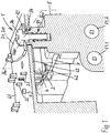
- in axonometrischer Ansicht im Teilausschnitt eine erfindungsgemäße Kühleinrichtung,
- Fig. 2
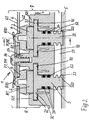
- in Schnittansicht II-II die Kühleinrichtung gemäß
Fig. 1 , - Fig. 3
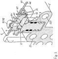
- in Ansicht der Schnittebene III-III die Kühleinrichtung in
Fig. 2 und - Fig. 4
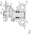
- in Detailansicht ein Kühlelement in Anordnung mit einem Kühlwasserkanal.
- Eine in
Fig. 1 bis 4 dargestellte erfindungsgemäße Kühleinrichtung 1 umfasst ein elektronisches Bauelement 2, im Ausführungsbeispiel einen Triac-Leistungsschalter, eine elektrische Leiterplatte 6, thermische Kühlelemente 3 und einen Lagerkörper 5. Bestandteile einer Klemmeinrichtung 7 sind erste Klemmflächen 71, gebildet durch eine Klemmplatte 70 und zweite Klemmflächen 72 sowie eine Schraubverbindung 73, mittels der die Klemmplatte 70 an dem Lagerkörper 5 angeordnet ist. - Die Klemmeinrichtung 7 umfasst einen doppelt vorgesehenen Klemmverbund 8. Dieser bildet jeweils eine Anordnungshälfte der Kühleinrichtung 1. Der Klemmverbund 8 ist dreiteilig ausgebildet, und zwar mit dem Kühlelement 3 in Form eines im Profilquerschnitt T-förmigen Kühlnippels aus wärmeleitendem Material, dem Bauelement 2 und einem Klemmhalter 4.
- Das Kühlelement 3 weist einen Kühlfuß 32 mit Kühlrippen 320 sowie ein durch eine Kopfplatte gebildetes Stützelement 33 auf, das das Kühlelement 3 innerhalb des Lagerkörpers 5 gegen die Klemmflächen 72 lagert. Eine plane Kopffläche des Stützelements 33 bildet eine Kühlfläche 31 des Kühlelements 3.
- Das Bauelement 2 weist zur Wärmeabführung eine plane Wärmeleitfläche 21 auf, mit der es im Klemmverbund 8 plan und damit flächig an der Kühlfläche 31 anliegt. Das Stützelement 33 des Kühlelements 3 bildet eine Fußseite des Klemmverbunds 8. Eine Kopfseite des Klemmverbunds 8 ist durch den Klemmhalter 4 gebildet. Man erkennt, dass im Klemmverbund 8 das Bauelement 2 zwischen dem Stützelement 33 und dem Klemmhalter 4 eingefügt ist.
- Die Leiterplatte 6 weist zwei Durchgriffsausnehmungen 64 auf, wobei jeweils eine Durchgriffsausnehmung 64 dem zugehörigen Klemmverbund 8 zugeordnet ist.
- Die zu dem Klemmverbund 8 zugehörigen Klemmflächen 71, 72 bilden ein Klemmflächenpaar, das den Klemmverbund 8 im Klemmsitz zwischen diesen Klemmflächen 71, 72 herstellt. Die erste Klemmfläche 71 erstreckt sich vor und zumindest im Wesentlichen parallel zu einer ersten Leiterplatten-Flächenseite 61, die von dem Bauelement 2 bzw. dem Kühlelement 3 abgewandt ist. Die andere zweite Flächenseite 62 der Leiterplatte 6, die mit der ersten Flächenseite 61 planparallel ist, ist dem Bauelement 2 bzw. dem vor dieser zweiten Flächenseite 62 angeordneten Stützelement 33 des Kühlelements 3 zugewandt. Die zweite Klemmfläche 72 erstreckt sich vor der zweiten Flächenseite 62 und ist zu dieser zumindest im Wesentlichen parallel. Eine Klemmeinrichtung mit einem oder mehreren parallelen Paaren paralleler erster und zweiter Klemmflächen ist nicht auf das Ausführungsbeispiel beschränkt.
- Aus der zuvor beschriebenen Anordnung geht hervor, dass die Kopfseite des Klemmverbundes 8 mit einem Kopfteil durch die Durchgriffsausnehmung 64 hindurchgreift, um die Anordnung des Klemmverbundes 8 zwischen den beiden Klemmflächen 71, 72 zu erhalten. Der Klemmhalter 4 bildet eine Kopffläche 81 des Klemmverbunds 8, die nahezu oder formschlüssig, jedoch gegebenenfalls nur mit gegenüber der Klemmkraft des Klemmverbunds 8 geringfügiger Kraft an der zweiten Flächenseite 62 zur Anlage kommt. Ein Vorsprung 810 an der Kopffläche 81, der den genannten Kopfteil des Klemmverbunds 8 bildet, fasst frei durch die Durchgriffsausnehmung 64 hindurch und liegt unter Klemmspannung an der ersten Klemmfläche 71 an. Obgleich der beschriebene Klemmverbund 8 mit dem Klemmhalter 4 besondere Vorteile aufweist, kann allgemein jeder Klemmverbund aus Kühlelement und elektronischem Bauelement, auch zweiteilig ohne Klemmhalter 4, vorgesehen werden. Auch der Klemmhalter 4 ist nicht auf die beschriebene Ausbildung beschränkt. Gegebenenfalls kann er auch mehrteilig sein. Ferner können an der Klemmplatte 70 bzw. den Klemmflächen 71 Erhebungen ausgebildet oder Vorsprünge angeordnet sein, die anstelle der Vorsprünge 81 durch die Durchgriffsausnehmungen hindurchgreifen.
- Im Ausführungsbeispiel ist die zweite Klemmfläche 72 eine passive Klemmfläche derart, dass sie für das Stützelement 33 ein festes, in den Lagerkörper 5 eingearbeitetes Widerlager bildet. In dem Lagerkörper 5 ist ein der T-förmigen Umfangskontur des Kühlelements 3 entsprechender Raum ausgebildet, in den das Kühlelement 3 eingesetzt ist. Dies geht im Detail aus der Ansicht in
Fig. 4 hervor. Das Kühlelement 3 weist eine Kopfbreite B auf, die kleiner ist als die lichte Weite zwischen zwei einander gegenüberliegenden Rändern 521, die eine Einfassung zur Aufnahme des T-Kopfes des Stützelements 33 bilden. Der dem Kühlfuß 32 angepasste Raum in dem Lagerkörper 5 bildet einen Schacht 52, in dem sich der Kühlfuß 32 im Dichtsitz befindet. Der Dichtsitz ist durch in Umfangsnuten am Kühlfuß 32 eingelegte Dichtringe 34 hergestellt. Das Kühlelement 3 lässt sich vor Anbringung des Bauelements 2 und des Klemmhalters 4 einfach montieren, indem das Kühlelement 3 in einer gegenüber der dargestellten Halteposition um 90° um seine Fußachse gedrehten Position eingesetzt und dann in die Halteposition gedreht wird. - Im Ausführungsbeispiel sind die beiden Klemmflächen 71 gleiche Teile der Klemmplatte 70. Sie bilden Klemmarme 711, 712, die jeweils ein mittels der Schraubverbindung 73 federelastisches, spannspares Klemmelement bilden. Wie insbesondere aus
Fig. 1 und2 ersichtlich, weist die Leiterplatte 6 mittig zwischen den beiden Klemmverbund-Anordnungen eine Ausnehmung 65 auf. Ein hervorstehendes domartiges Sockelelement 54 des Lagerkörpers 5 fasst mit einem äußeren zurückspringenden Rand durch die Ausnehmung 65 hindurch und weist eine Innenbohrung einer Schraubverbindung 73 auf. Eine mit ihrem Kopfhals an der Klemmplatte 70 angreifende Kopfschraube 74 ist in die Innenbohrung eingedreht. Es ist eine Spanneinrichtung gebildet, mit der sich die Spann-/Klemmkraft über die federelastischen Platten-Klemmarme 711, 712 in definiertem Maß je nach Anzug der Kopfschraube gezielt einstellen lässt. Mittels der Schraubverbindung 73 wirken die Klemmflächen 71 als aktive Klemmflächen. Erfindungsgemäße Kühleinrichtungen können auch aktiv mit Spannkraft beaufschlagbare zweite Klemmflächen zusätzlich zu aktiven oder in Kombination mit passiven (festen) ersten Klemmflächen aufweisen. Weiterhin kann jedem Klemmverbund 8 ein separates Spannmittels zugeordnet werden. - Im Ausführungsbeispiel weist der vorzugsweise aus Kunststoff geformte Klemmhalter 4 eine kappenartige Form mit Formrändern 42 auf. Zwischen den Formrändern 42 ist ein Sitz für das Bauelement 2 ausgebildet, der dergestalt ist, dass auch Bauelemente 2 mit unterschiedlicher Gehäusedimension, insbesondere solche mit Toleranzabweichungen der Bauform aufgenommen werden können. Insbesondere der Auswirkung von Toleranzabweichungen kann zum Herstellen einer dennoch in jedem Fall zuverlässigen und stabilen Kühlverbindung durch Einstellung der Spann-Klemmkraft begegnet werden. Der eine Formrand 42 bildet einen Rand, an dem die Anschlusspins 22 unter Ausbildung definierte Abknicklänge und Ausrichtung zu Anschlussstellen 63 der Leiterplatte 6 abgebogen sind. Üblicherweise sind die Anschlusspins 22 in Lötverbindung an zugeordneten Anschlussstellen 63 der Leiterplatte 6 verbunden. Allgemein ist es nicht erforderlich, dass der Klemmhalter mit einer besonderen Sitzausnehmung für das elektrische Bauelement 2 geformt wird.
- Im Ausführungsbeispiel bleibt die Leiterplatte 6 im Bereich, das heißt in der Umgebung der Bauelemente 2 und deren Anschlusspins 22 frei von mechanischer Befestigung an dem Lagerkörper 5. Die nur im Ausschnitt dargestellte Lagerplatte 6 ist an von dem Anordnungsbereich der Kühleinrichtung 1 entfernt gelegenen Stellen, vorzugsweise mittels nicht dargestellter Dreipunkt-Lagerung an dem Lagerkörper 5 befestigt. Man erreicht mit diesen Maßnahmen besondere Vorteile zur Montage der Bauelemente 2 insbesondere in Verbindung mit den Klemmhaltern 4. Toleranzen oder auch größeren Unterschieden der Dimensionen der Bauelemente 2 kann entsprochen werden. Gegebenenfalls kann die Leiterplatte 6 durch den Klemmhalter 4 minimal in Richtung der Klemmfläche 71 verdrängt werden, um ein Bauelement 2 aufzunehmen, dessen Bauhöhe zwischen den Klemmflächen 71, 72 geringfügig größer ist als die eines anderen, die Plattenverdrängung vermeidenden Bauelements. Wesentlich bleibt, dass die Spannkraft zum Herstellen des Kühl-Klemmverbunds 8 im Wesentlichen zwischen den Klemmflächen 71, 72 aufgebracht wird. Die Leiterplatte 6 kann, wie im Ausführungsbeispiel, an dem zurückspringenden Rand des Sockelelements 54 formschlüssig zur Stützung anliegen und gegebenenfalls mittels des Sockelelements 54 zur Montage oder bei geringfügigem Abheben geführt sein. Zu diesem Zweck ist auch ein an dem Lagerkörper 5 hervorragender Führungsstift 53 vorgesehen, der senkrecht zu den Flächen der Leiterplatte 6 gerichtet ist. Die senkrechte Führung ist auf das Ausführungsbeispiel nicht beschränkt.
- In
Fig. 1 bis 4 ist die Kühleinrichtung 1 Bestandteil eines nicht näher dargestellten elektronisch gesteuerten Durchlauferhitzers mit elektrischer Heizeinrichtung zum Erwärmen von durch den Durchlauferhitzer fließendem Wasser. Der Lagerkörper 5 bildet einen Montage-Grundkörper, der mit wesentlichen Teilen und Funktionsbereichen des Durchlauferhitzers ausgestattet ist. Es handelt sich im Ausführungsbeispiel um einen Durchlauferhitzer mit einer Heizeinrichtung, die zum Beispiel durch eine Blankdraht-Heizkartusche gebildet ist. Der nicht dargestellten Heizeinrichtung bzw. Heizkartusche kann durch einen (nicht dargestellten) Zulaufstutzen des Durchlauferhitzers unter Druck eingespeistes Wasser über Wasserkanäle 51.1 und 51.2 zugeführt werden. Wie ausFig. 1 und4 hervorgeht, sind die die Kühlrippen 320 aufweisenden Kühlfüße 32 der Kühlelemente 3 in dem Kaltwasser-Kanal 51.2, sich darin quer erstreckend, angeordnet. In dem besonderen Ausführungsbeispiel ist die Anordnung der Kühlelemente 3 derart, dass die Stützelemente 33 in den zugehörigen T-Kopf Lagerausnehmungen mit geringstem Spiel s, zum Beispiel in der Größenordnung von 1/10 mm, in Richtung der ersten Klemmflächen 71 frei und ausweichlich sind. Man erreicht dadurch, dass die Kühlelemente 3 unter Druckbeaufschlagung mit Wasser innerhalb des Kanals 51.2 in Richtung auf die ersten Klemmflächen 71 eine zusätzliche Klemmkraft jeweils auf den Klemmverbund 8 aufbringen können. In dieser Anordnung und Gestaltung wird das Stützelement 33 gegen Wasserdruck gegebenenfalls geringfügig von der zweiten Klemmfläche 72 abgehoben, wie in den Figuren dargestellt. Flächen des Kühlfußes 32, im Ausführungsbeispiel der radialen Kühlrippen 320, wirken zusätzlich als Klemm- bzw. Stützflächen zur Klemmung. - Die Klemmspannung der Klemmplatte 70 und die Klemmspannung der druckbeaufschlagten Kühlelemente 3 kann genau aufeinander abgestimmt werden. Beim Einleiten von Wasser in den Durchlauferhitzer steht das Wasser in den Kanälen 51.1, 51.2 unter Wasserleitungsdruck. Der Wasserfluss bewirkt das Schalten der elektronischen Bausteine 2, nämlich der Triac-Leistungsschalter, so dass die Heizeinrichtung durch Bestromen eines Heizelements, z.B. der Blankdraht-Heizkartusche, in Betrieb gesetzt wird. Der dadurch bedingten Erwärmung der elektronischen Bauelemente 2 wird durch besonders wirksame und zuverlässige Kühlung begegnet, indem die druckbeaufschlagten Kühlelemente 3 eine besonders verstärkte Anpressung von Wärmeleitflächen und Kühlflächen jeweils in dem Klemmverbund 8 bewirken. Die zusätzlichen druckbeaufschlagten Kühlfüße 32 können in jedem Warmwassergerät mit zu kühlenden elektronischen Bauelementen zum Einsatz kommen. Die Erfindung ist jedoch nicht auf die Nutzung der zusätzlich aktiv druckbeaufschlagten Kühlfüße 32 beschränkt. Anstelle der Kühlelemente 3 des Ausführungsbeispiels, insbesondere auch in elektrischen Warmwassergeräten/Durchlauferhitzern, können sämtliche zur thermischen Wärmeabfuhr geeignete Kühlelemente vorgesehen werden, z.B. insbesondere auch Luftkühlungselemente und/oder Kühlelemente, die Wärme thermisch an andere Elemente abgeben.
Claims (14)
- Kühleinrichtung (1) eines elektronischen, sich erwärmenden Bauelements (2), umfassend das eine Wärmeleitfläche (21) zur Wärmeabführung sowie elektrische Anschlusspins (22) aufweisende elektronische Bauelement (2), eine zwei einander gegenüberliegende Flächenseiten (61, 62) aufweisende elektrische Leiterplatte (6) mit Anschlussstellen (63), mit denen die elektrischen Anschlusspins (22) verbunden sind, ein thermisches Kühlelement (3) mit einer Kühlfläche (31), die an der Wärmeleitfläche (21) anliegt, und einen Lagerkörper (5), an dem die Leiterplatte (6) gelagert ist, wobei die Kühleinrichtung (1) eine Klemmeinrichtung (7) mit einander zugewandten, an dem Lagerkörper (5) angeordneten Klemmflächen (71, 72) aufweist, wobei wenigstens eine erste Klemmfläche (71) vor der einen ersten Flächenseite (61) der Leiterplatte (6) und wenigstens eine zweite Klemmfläche (72) vor der anderen zweiten Flächenseite (62) der Leiterplatte (6) derart angeordnet sind, dass sich die Leiterplatte (6) zwischen den Klemmflächen (71, 72) erstreckt, wobei das Kühlelement (3) und das elektronische Bauelement (2) im Klemmverbund (8) mit aneinander liegender Kühlfläche (31) und Wärmeleitfläche (21) zwischen der ersten Klemmfläche (71) und der zweiten zugehörigen Klemmfläche (72) klemmend eingefügt sind, wobei die Leiterplatte (6) eine einen räumlichen Durchgriff für den Klemmverbund (8) bildende Durchgriffsausnehmung (64) aufweist und wobei der Klemmverbund (8) eine der Durchgriffsausnehmung (64) sowie der ersten Klemmfläche (71) zugeordnete Kopfseite und eine der zweiten Klemmfläche (72) zugeordnete, wenigstens durch einen Teil des Kühlelements (3) gebildete Fußseite umfasst, wobei das Kühlelement (3) einen zur Wärmeabgabe an Flüssigkeit ausgebildeten, in diese eintauchbaren Kühlfuß (32) sowie ein Stützelement (33) zur Klemmanlage gegen die zweite Klemmfläche (72) aufweist.
- Kühleinrichtung nach Anspruch 1, dadurch gekennzeichnet, dass der Klemmverbund (8) durch das Kühlelement (3), einen Klemmhalter (4) und, in Klemmanordnung zwischen dem Kühlelement (3) und dem Klemmhalter (4), das elektronische Bauelement (2) gebildet ist.
- Kühleinrichtung nach Anspruch 2, dadurch gekennzeichnet, dass der Klemmhalter (4) an der Kopfseite des Klemmverbunds (8) eine der ersten Klemmfläche (71) zugewandte Kopffläche (81) aufweist, an der wenigstens ein an der Kopffläche (81) hervorstehender, die Durchgriffsausnehmung (64) durchgreifender, in Klemmanlage an der ersten Klemmfläche (71) befindlicher Vorsprung (810) ausgebildet ist.
- Kühleinrichtung nach Anspruch 2 oder 3, dadurch gekennzeichnet, dass der Klemmhalter (4) einen den Anschlusspins (22) zugeordneten Formrand (42) aufweist, an dem die Anschlusspins (22) unter Ausbildung definierter Abknicklänge und Ausrichtung zu den Anschlussstellen (63) der Leiterplatte (6) abgebogen sind.
- Kühleinrichtung nach einem der Ansprüche 2 bis 4, dadurch gekennzeichnet, dass der Klemmhalter (4) zwischen der Leiterplatte (6) und den an den Anschlussstellen (63) der Leiterplatte (6) befestigten Anschlusspins (22) gefangen gehalten ist.
- Kühleinrichtung nach einem der Ansprüche 2 bis 5, dadurch gekennzeichnet, dass der Klemmhalter (4) so ausgebildet ist, dass sich wenigstens zwei elektronische Bauelemente (2) jeweils im Klemmverbund (8) mit dem Klemmhalter (4) befinden.
- Kühleinrichtung nach einem der Ansprüche 1 bis 6, dadurch gekennzeichnet, dass die Leiterplatte (6) eine Ausnehmung (65) aufweist, durch die wenigstens ein Verbindungselement hindurchfasst, das die erste Klemmfläche (71) mit dem Lagerkörper (5) verbindet.
- Kühleinrichtung nach Anspruch 7, dadurch gekennzeichnet, dass das wenigstens eine Verbindungselement Bestandteil einer Schraubverbindung (73) ist.
- Kühleinrichtung nach einem der Ansprüche 1 bis 8, dadurch gekennzeichnet, dass die erste Klemmfläche (71) durch einen Klemmarm (711, 712) gebildet ist.
- Kühleinrichtung nach einem der Ansprüche 1 bis 9, dadurch gekennzeichnet, dass mehrere erste Klemmflächen (71) durch wenigstens zwei Klemmarme (711, 712) gebildet sind, die mittels gemeinsamer Verbindung (73) an dem Lagerkörper (5) befestigt sind.
- Kühleinrichtung nach Anspruch 1 bis 10, dadurch gekennzeichnet, dass der Lagerkörper (5) einen zum Führen von unter Druck stehender Flüssigkeit eingerichteten Flüssigkeitskanal (51) und einen in den Flüssigkeitskanal (51) mündenden Schacht (52) umfasst, der den Kühlfuß (32) im gegen Flüssigkeitsdurchtritt gedichteten Sitz aufnimmt, wobei ein zur Wärmeabgabe ausgebildetes Fußende des Kühlfußes (32) in den Flüssigkeitskanal (51) hineinragt, und dass das Kühlelement (3) bei klemmender Anlageposition an der zweiten Klemmfläche (72) zur Übertragung von zusätzlicher Klemmkraft frei gehalten ist.
- Kühleinrichtung nach einem der Ansprüche 1 bis 11, dadurch gekennzeichnet, dass die Leiterplatte (6) im Anordnungsbereich des elektronischen Bauelements (2) von mechanischer Befestigung mit dem Lagerkörper (5) frei ist.
- Kühleinrichtung nach Anspruch 12, dadurch gekennzeichnet, dass der Lagerkörper (5) in dem Anordnungsbereich des elektronischen Bauelements (2) wenigstens ein Führungselement (53) zur zumindest im Wesentlichen mit ihren Flächenseiten (61, 62) flächenparallelen Führungspositionierung der Leiterplatte (6) aufweist.
- Durchlauferhitzer mit elektrischer Heizeinrichtung zum Erwärmen von durch den Durchlauferhitzer fließendem Wasser, wobei die Heizeinrichtung wenigstens ein zu kühlendes elektronisches Bauelement als zum Regeln der Warmwassertemperatur ansteuerbarer Leistungsschalter sowie eine Kühleinrichtung (1) zum Kühlen des Leistungsschalters umfasst, wobei die Kühleinrichtung (1) in thermischer Verbindung mit wenigstens einer Wärmeleitfläche (21) des Leistungsschalters stehende Kühlelemente (3) aufweist, die Wärme an zu erwärmendes Wasser abgeben, dadurch gekennzeichnet, dass die Kühleinrichtung (1) durch eine Kühleinrichtung (1) nach einem der Ansprüche 1 bis 13 gebildet ist.
Priority Applications (2)
| Application Number | Priority Date | Filing Date | Title |
|---|---|---|---|
| EP11155224.6A EP2489956B2 (de) | 2011-02-21 | 2011-02-21 | Kühleinrichtung eines elektrischen, sich erwärmenden Bauelements |
| CN201210100348.9A CN102647888B (zh) | 2011-02-21 | 2012-02-21 | 发热的电子元器件的散热机构 |
Applications Claiming Priority (1)
| Application Number | Priority Date | Filing Date | Title |
|---|---|---|---|
| EP11155224.6A EP2489956B2 (de) | 2011-02-21 | 2011-02-21 | Kühleinrichtung eines elektrischen, sich erwärmenden Bauelements |
Publications (4)
| Publication Number | Publication Date |
|---|---|
| EP2489956A1 EP2489956A1 (de) | 2012-08-22 |
| EP2489956A9 EP2489956A9 (de) | 2012-10-31 |
| EP2489956B1 EP2489956B1 (de) | 2017-04-05 |
| EP2489956B2 true EP2489956B2 (de) | 2020-09-09 |
Family
ID=44280995
Family Applications (1)
| Application Number | Title | Priority Date | Filing Date |
|---|---|---|---|
| EP11155224.6A Active EP2489956B2 (de) | 2011-02-21 | 2011-02-21 | Kühleinrichtung eines elektrischen, sich erwärmenden Bauelements |
Country Status (2)
| Country | Link |
|---|---|
| EP (1) | EP2489956B2 (de) |
| CN (1) | CN102647888B (de) |
Families Citing this family (4)
| Publication number | Priority date | Publication date | Assignee | Title |
|---|---|---|---|---|
| FR3020999B1 (fr) * | 2014-05-16 | 2016-07-01 | Alstom Transp Tech | Element d'isolation electrique entre un dispositif electrique et un organe de refroidissement du dispositif electrique ; systeme de refroidissement comprenant un tel element |
| DE102018207943A1 (de) * | 2018-05-22 | 2019-11-28 | Zf Friedrichshafen Ag | Elektronikmodul zur Anordnung an einem Getriebebauteil und Verfahren zur Anordnung eines Elektronikmoduls an einem Getriebebauteil |
| FR3103887A1 (fr) * | 2019-11-29 | 2021-06-04 | Valeo Systemes Thermiques | Dispositif de chauffage électrique d’un liquide caloporteur pour véhicule automobile |
| EP4187171B1 (de) | 2021-11-26 | 2025-07-02 | Kospel spólka z o.o. | Durchlauferhitzer |
Citations (6)
| Publication number | Priority date | Publication date | Assignee | Title |
|---|---|---|---|---|
| DE2728564A1 (de) † | 1977-06-24 | 1979-01-11 | Siemens Ag | Halbleiterbauelement |
| US4756081A (en) † | 1985-08-22 | 1988-07-12 | Dart Controls, Inc. | Solid state device package mounting method |
| US5483103A (en) † | 1994-02-24 | 1996-01-09 | Harris Corporation | Means for clamping a semi-conductor to a support |
| US20010008046A1 (en) † | 2000-01-14 | 2001-07-19 | Ing. Guido Scheyer Sola-Messwerkzeuge Gesellschaft M.B.H. & Co. | Level |
| EP2226590A1 (de) † | 2003-03-21 | 2010-09-08 | BSH Bosch und Siemens Hausgeräte GmbH | Durchlauferhitzer |
| EP2455680A2 (de) † | 2010-11-19 | 2012-05-23 | STIEBEL ELTRON GmbH & Co. KG | Elektrischer Durchlauferhitzer |
Family Cites Families (6)
| Publication number | Priority date | Publication date | Assignee | Title |
|---|---|---|---|---|
| CS214034B1 (en) * | 1980-06-10 | 1982-04-09 | Michal Pellant | Semiconductor modulus |
| DE3143336A1 (de) * | 1981-10-31 | 1983-05-19 | SEMIKRON Gesellschaft für Gleichrichterbau u. Elektronik mbH, 8500 Nürnberg | Halbleitergleichrichterbaueinheit |
| KR100214560B1 (ko) * | 1997-03-05 | 1999-08-02 | 구본준 | 반도체 멀티칩 모듈 |
| US6055154A (en) * | 1998-07-17 | 2000-04-25 | Lucent Technologies Inc. | In-board chip cooling system |
| US6892796B1 (en) * | 2000-02-23 | 2005-05-17 | General Motors Corporation | Apparatus and method for mounting a power module |
| DE202004012263U1 (de) | 2004-08-05 | 2004-10-07 | Stiebel Eltron Gmbh & Co. Kg | Durchlauferhitzer |
-
2011
- 2011-02-21 EP EP11155224.6A patent/EP2489956B2/de active Active
-
2012
- 2012-02-21 CN CN201210100348.9A patent/CN102647888B/zh active Active
Patent Citations (6)
| Publication number | Priority date | Publication date | Assignee | Title |
|---|---|---|---|---|
| DE2728564A1 (de) † | 1977-06-24 | 1979-01-11 | Siemens Ag | Halbleiterbauelement |
| US4756081A (en) † | 1985-08-22 | 1988-07-12 | Dart Controls, Inc. | Solid state device package mounting method |
| US5483103A (en) † | 1994-02-24 | 1996-01-09 | Harris Corporation | Means for clamping a semi-conductor to a support |
| US20010008046A1 (en) † | 2000-01-14 | 2001-07-19 | Ing. Guido Scheyer Sola-Messwerkzeuge Gesellschaft M.B.H. & Co. | Level |
| EP2226590A1 (de) † | 2003-03-21 | 2010-09-08 | BSH Bosch und Siemens Hausgeräte GmbH | Durchlauferhitzer |
| EP2455680A2 (de) † | 2010-11-19 | 2012-05-23 | STIEBEL ELTRON GmbH & Co. KG | Elektrischer Durchlauferhitzer |
Also Published As
| Publication number | Publication date |
|---|---|
| EP2489956B1 (de) | 2017-04-05 |
| CN102647888A (zh) | 2012-08-22 |
| EP2489956A1 (de) | 2012-08-22 |
| EP2489956A9 (de) | 2012-10-31 |
| CN102647888B (zh) | 2016-06-01 |
Similar Documents
| Publication | Publication Date | Title |
|---|---|---|
| DE69632865T2 (de) | Transistor-lötclip und kühlkörper | |
| EP2337425B1 (de) | Elektrische Heizvorrichtung und wärmeerzeugendes Element einer elektrischen Heizvorrichtung | |
| DE60319523T2 (de) | Vorrichtung zur Kühlung von Halbleiterbauteilen auf Leiterplatten | |
| EP2316254B1 (de) | Elektronikmodul | |
| DE3612862A1 (de) | Kuehlkoerperbefestigungsanordnung fuer einen halbleiter | |
| DE102015202591B4 (de) | Elektronikkomponentenbefestigungsaufbau und Befestigungsverfahren | |
| DE102010062410A1 (de) | Elektrischer Stecker und Wärmesenke | |
| EP2489956B2 (de) | Kühleinrichtung eines elektrischen, sich erwärmenden Bauelements | |
| DE19531628A1 (de) | Kühlkörper | |
| DE102011088322B4 (de) | VERBINDUNGSSYSTEM ZUM ELEKTRISCHEN ANSCHLIEßEN ELEKTRISCHER GERÄTE, LEISTUNGSHALBLEITERMODULSYSTEM, VERFAHREN ZUM VERBINDEN EINES ELEKTRISCH LEITENDEN ERSTEN ANSCHLUSSES UND EINES ELEKTRISCH LEITENDEN ZWEITEN ANSCHLUSSES, UND VERFAHREN ZUR HERSTELLUNG | |
| DE102005049872B4 (de) | IC-Bauelement mit Kühlanordnung | |
| EP2122680A1 (de) | Transistorklemmvorrichtung | |
| DE3927755C2 (de) | Wärmeableitvorrichtung für elektrische Bauelemente | |
| EP3271979B1 (de) | Modulares system | |
| WO2009077268A2 (de) | Kühlkörper wenigstens eines elektrischen bauteils | |
| DE102006052872A1 (de) | Elektrisches Leistungsmodul | |
| DE102008015785B4 (de) | Elektroniksubstrat-Montagestruktur | |
| DE102020209923B3 (de) | Schaltungsträgeranordnung und Verfahren zum Herstellen einer solchen Schaltungsträgeranordnung | |
| EP1095547A1 (de) | Fadenbearbeitungssystem | |
| DE10246577A1 (de) | Leiterplatte mit Metallgehäuse | |
| DE102006014145C5 (de) | Druck kontaktierte Anordnung mit einem Leistungsbauelement, einem Metallformkörper und einer Verbindungseinrichtung | |
| EP1953820B1 (de) | Leistungshalbleitermodul | |
| DE10206271A1 (de) | Wärmeableitvorrichtung | |
| DE102008051560A1 (de) | Leistungshalbleitermodul | |
| DE102022211729A1 (de) | Vorbaugruppe zur Positionierung von elektrischen Leistungsbauelementen, Verfahren zum Zusammensetzen der Vordergruppe |
Legal Events
| Date | Code | Title | Description |
|---|---|---|---|
| PUAI | Public reference made under article 153(3) epc to a published international application that has entered the european phase |
Free format text: ORIGINAL CODE: 0009012 |
|
| AK | Designated contracting states |
Kind code of ref document: A1 Designated state(s): AL AT BE BG CH CY CZ DE DK EE ES FI FR GB GR HR HU IE IS IT LI LT LU LV MC MK MT NL NO PL PT RO RS SE SI SK SM TR |
|
| AX | Request for extension of the european patent |
Extension state: BA ME |
|
| 17P | Request for examination filed |
Effective date: 20130220 |
|
| REG | Reference to a national code |
Ref country code: HK Ref legal event code: DE Ref document number: 1176109 Country of ref document: HK |
|
| GRAP | Despatch of communication of intention to grant a patent |
Free format text: ORIGINAL CODE: EPIDOSNIGR1 |
|
| INTG | Intention to grant announced |
Effective date: 20160920 |
|
| GRAS | Grant fee paid |
Free format text: ORIGINAL CODE: EPIDOSNIGR3 |
|
| GRAA | (expected) grant |
Free format text: ORIGINAL CODE: 0009210 |
|
| AK | Designated contracting states |
Kind code of ref document: B1 Designated state(s): AL AT BE BG CH CY CZ DE DK EE ES FI FR GB GR HR HU IE IS IT LI LT LU LV MC MK MT NL NO PL PT RO RS SE SI SK SM TR |
|
| REG | Reference to a national code |
Ref country code: GB Ref legal event code: FG4D Free format text: NOT ENGLISH |
|
| REG | Reference to a national code |
Ref country code: CH Ref legal event code: EP |
|
| REG | Reference to a national code |
Ref country code: AT Ref legal event code: REF Ref document number: 882201 Country of ref document: AT Kind code of ref document: T Effective date: 20170415 |
|
| REG | Reference to a national code |
Ref country code: IE Ref legal event code: FG4D Free format text: LANGUAGE OF EP DOCUMENT: GERMAN |
|
| REG | Reference to a national code |
Ref country code: DE Ref legal event code: R096 Ref document number: 502011011963 Country of ref document: DE |
|
| REG | Reference to a national code |
Ref country code: NL Ref legal event code: MP Effective date: 20170405 |
|
| REG | Reference to a national code |
Ref country code: LT Ref legal event code: MG4D |
|
| PG25 | Lapsed in a contracting state [announced via postgrant information from national office to epo] |
Ref country code: NL Free format text: LAPSE BECAUSE OF FAILURE TO SUBMIT A TRANSLATION OF THE DESCRIPTION OR TO PAY THE FEE WITHIN THE PRESCRIBED TIME-LIMIT Effective date: 20170405 |
|
| PG25 | Lapsed in a contracting state [announced via postgrant information from national office to epo] |
Ref country code: GR Free format text: LAPSE BECAUSE OF FAILURE TO SUBMIT A TRANSLATION OF THE DESCRIPTION OR TO PAY THE FEE WITHIN THE PRESCRIBED TIME-LIMIT Effective date: 20170706 Ref country code: LT Free format text: LAPSE BECAUSE OF FAILURE TO SUBMIT A TRANSLATION OF THE DESCRIPTION OR TO PAY THE FEE WITHIN THE PRESCRIBED TIME-LIMIT Effective date: 20170405 Ref country code: FI Free format text: LAPSE BECAUSE OF FAILURE TO SUBMIT A TRANSLATION OF THE DESCRIPTION OR TO PAY THE FEE WITHIN THE PRESCRIBED TIME-LIMIT Effective date: 20170405 Ref country code: NO Free format text: LAPSE BECAUSE OF FAILURE TO SUBMIT A TRANSLATION OF THE DESCRIPTION OR TO PAY THE FEE WITHIN THE PRESCRIBED TIME-LIMIT Effective date: 20170705 Ref country code: ES Free format text: LAPSE BECAUSE OF FAILURE TO SUBMIT A TRANSLATION OF THE DESCRIPTION OR TO PAY THE FEE WITHIN THE PRESCRIBED TIME-LIMIT Effective date: 20170405 Ref country code: HR Free format text: LAPSE BECAUSE OF FAILURE TO SUBMIT A TRANSLATION OF THE DESCRIPTION OR TO PAY THE FEE WITHIN THE PRESCRIBED TIME-LIMIT Effective date: 20170405 |
|
| PG25 | Lapsed in a contracting state [announced via postgrant information from national office to epo] |
Ref country code: IS Free format text: LAPSE BECAUSE OF FAILURE TO SUBMIT A TRANSLATION OF THE DESCRIPTION OR TO PAY THE FEE WITHIN THE PRESCRIBED TIME-LIMIT Effective date: 20170805 Ref country code: SE Free format text: LAPSE BECAUSE OF FAILURE TO SUBMIT A TRANSLATION OF THE DESCRIPTION OR TO PAY THE FEE WITHIN THE PRESCRIBED TIME-LIMIT Effective date: 20170405 Ref country code: LV Free format text: LAPSE BECAUSE OF FAILURE TO SUBMIT A TRANSLATION OF THE DESCRIPTION OR TO PAY THE FEE WITHIN THE PRESCRIBED TIME-LIMIT Effective date: 20170405 Ref country code: BG Free format text: LAPSE BECAUSE OF FAILURE TO SUBMIT A TRANSLATION OF THE DESCRIPTION OR TO PAY THE FEE WITHIN THE PRESCRIBED TIME-LIMIT Effective date: 20170705 Ref country code: RS Free format text: LAPSE BECAUSE OF FAILURE TO SUBMIT A TRANSLATION OF THE DESCRIPTION OR TO PAY THE FEE WITHIN THE PRESCRIBED TIME-LIMIT Effective date: 20170405 Ref country code: PL Free format text: LAPSE BECAUSE OF FAILURE TO SUBMIT A TRANSLATION OF THE DESCRIPTION OR TO PAY THE FEE WITHIN THE PRESCRIBED TIME-LIMIT Effective date: 20170405 |
|
| REG | Reference to a national code |
Ref country code: DE Ref legal event code: R026 Ref document number: 502011011963 Country of ref document: DE |
|
| PLBI | Opposition filed |
Free format text: ORIGINAL CODE: 0009260 |
|
| PLAX | Notice of opposition and request to file observation + time limit sent |
Free format text: ORIGINAL CODE: EPIDOSNOBS2 |
|
| PG25 | Lapsed in a contracting state [announced via postgrant information from national office to epo] |
Ref country code: DK Free format text: LAPSE BECAUSE OF FAILURE TO SUBMIT A TRANSLATION OF THE DESCRIPTION OR TO PAY THE FEE WITHIN THE PRESCRIBED TIME-LIMIT Effective date: 20170405 Ref country code: EE Free format text: LAPSE BECAUSE OF FAILURE TO SUBMIT A TRANSLATION OF THE DESCRIPTION OR TO PAY THE FEE WITHIN THE PRESCRIBED TIME-LIMIT Effective date: 20170405 Ref country code: CZ Free format text: LAPSE BECAUSE OF FAILURE TO SUBMIT A TRANSLATION OF THE DESCRIPTION OR TO PAY THE FEE WITHIN THE PRESCRIBED TIME-LIMIT Effective date: 20170405 Ref country code: SK Free format text: LAPSE BECAUSE OF FAILURE TO SUBMIT A TRANSLATION OF THE DESCRIPTION OR TO PAY THE FEE WITHIN THE PRESCRIBED TIME-LIMIT Effective date: 20170405 Ref country code: RO Free format text: LAPSE BECAUSE OF FAILURE TO SUBMIT A TRANSLATION OF THE DESCRIPTION OR TO PAY THE FEE WITHIN THE PRESCRIBED TIME-LIMIT Effective date: 20170405 |
|
| 26 | Opposition filed |
Opponent name: STIEBEL ELTRON GMBH & CO. KG Effective date: 20180105 |
|
| PG25 | Lapsed in a contracting state [announced via postgrant information from national office to epo] |
Ref country code: SM Free format text: LAPSE BECAUSE OF FAILURE TO SUBMIT A TRANSLATION OF THE DESCRIPTION OR TO PAY THE FEE WITHIN THE PRESCRIBED TIME-LIMIT Effective date: 20170405 Ref country code: IT Free format text: LAPSE BECAUSE OF FAILURE TO SUBMIT A TRANSLATION OF THE DESCRIPTION OR TO PAY THE FEE WITHIN THE PRESCRIBED TIME-LIMIT Effective date: 20170405 |
|
| REG | Reference to a national code |
Ref country code: HK Ref legal event code: GR Ref document number: 1176109 Country of ref document: HK |
|
| PLBB | Reply of patent proprietor to notice(s) of opposition received |
Free format text: ORIGINAL CODE: EPIDOSNOBS3 |
|
| PG25 | Lapsed in a contracting state [announced via postgrant information from national office to epo] |
Ref country code: SI Free format text: LAPSE BECAUSE OF FAILURE TO SUBMIT A TRANSLATION OF THE DESCRIPTION OR TO PAY THE FEE WITHIN THE PRESCRIBED TIME-LIMIT Effective date: 20170405 |
|
| REG | Reference to a national code |
Ref country code: CH Ref legal event code: PL |
|
| PG25 | Lapsed in a contracting state [announced via postgrant information from national office to epo] |
Ref country code: MT Free format text: LAPSE BECAUSE OF FAILURE TO SUBMIT A TRANSLATION OF THE DESCRIPTION OR TO PAY THE FEE WITHIN THE PRESCRIBED TIME-LIMIT Effective date: 20170405 Ref country code: MC Free format text: LAPSE BECAUSE OF FAILURE TO SUBMIT A TRANSLATION OF THE DESCRIPTION OR TO PAY THE FEE WITHIN THE PRESCRIBED TIME-LIMIT Effective date: 20170405 |
|
| REG | Reference to a national code |
Ref country code: IE Ref legal event code: MM4A |
|
| REG | Reference to a national code |
Ref country code: BE Ref legal event code: MM Effective date: 20180228 |
|
| PG25 | Lapsed in a contracting state [announced via postgrant information from national office to epo] |
Ref country code: CH Free format text: LAPSE BECAUSE OF NON-PAYMENT OF DUE FEES Effective date: 20180228 Ref country code: LU Free format text: LAPSE BECAUSE OF NON-PAYMENT OF DUE FEES Effective date: 20180221 Ref country code: LI Free format text: LAPSE BECAUSE OF NON-PAYMENT OF DUE FEES Effective date: 20180228 |
|
| REG | Reference to a national code |
Ref country code: FR Ref legal event code: ST Effective date: 20181031 |
|
| PG25 | Lapsed in a contracting state [announced via postgrant information from national office to epo] |
Ref country code: IE Free format text: LAPSE BECAUSE OF NON-PAYMENT OF DUE FEES Effective date: 20180221 |
|
| PG25 | Lapsed in a contracting state [announced via postgrant information from national office to epo] |
Ref country code: BE Free format text: LAPSE BECAUSE OF NON-PAYMENT OF DUE FEES Effective date: 20180228 Ref country code: FR Free format text: LAPSE BECAUSE OF NON-PAYMENT OF DUE FEES Effective date: 20180228 |
|
| REG | Reference to a national code |
Ref country code: AT Ref legal event code: MM01 Ref document number: 882201 Country of ref document: AT Kind code of ref document: T Effective date: 20180221 |
|
| REG | Reference to a national code |
Ref country code: DE Ref legal event code: R082 Ref document number: 502011011963 Country of ref document: DE Representative=s name: STORK BAMBERGER PATENTANWAELTE PARTMBB, DE Ref country code: DE Ref legal event code: R081 Ref document number: 502011011963 Country of ref document: DE Owner name: GERDES HOLDING GMBH & CO. KG, DE Free format text: FORMER OWNER: GERDES OHG, 21337 LUENEBURG, DE |
|
| PG25 | Lapsed in a contracting state [announced via postgrant information from national office to epo] |
Ref country code: AT Free format text: LAPSE BECAUSE OF NON-PAYMENT OF DUE FEES Effective date: 20180221 |
|
| RAP2 | Party data changed (patent owner data changed or rights of a patent transferred) |
Owner name: GERDES HOLDING GMBH & CO. KG |
|
| APBM | Appeal reference recorded |
Free format text: ORIGINAL CODE: EPIDOSNREFNO |
|
| APBP | Date of receipt of notice of appeal recorded |
Free format text: ORIGINAL CODE: EPIDOSNNOA2O |
|
| APAH | Appeal reference modified |
Free format text: ORIGINAL CODE: EPIDOSCREFNO |
|
| APBM | Appeal reference recorded |
Free format text: ORIGINAL CODE: EPIDOSNREFNO |
|
| APBP | Date of receipt of notice of appeal recorded |
Free format text: ORIGINAL CODE: EPIDOSNNOA2O |
|
| PG25 | Lapsed in a contracting state [announced via postgrant information from national office to epo] |
Ref country code: TR Free format text: LAPSE BECAUSE OF FAILURE TO SUBMIT A TRANSLATION OF THE DESCRIPTION OR TO PAY THE FEE WITHIN THE PRESCRIBED TIME-LIMIT Effective date: 20170405 |
|
| APBU | Appeal procedure closed |
Free format text: ORIGINAL CODE: EPIDOSNNOA9O |
|
| PG25 | Lapsed in a contracting state [announced via postgrant information from national office to epo] |
Ref country code: HU Free format text: LAPSE BECAUSE OF FAILURE TO SUBMIT A TRANSLATION OF THE DESCRIPTION OR TO PAY THE FEE WITHIN THE PRESCRIBED TIME-LIMIT; INVALID AB INITIO Effective date: 20110221 Ref country code: PT Free format text: LAPSE BECAUSE OF FAILURE TO SUBMIT A TRANSLATION OF THE DESCRIPTION OR TO PAY THE FEE WITHIN THE PRESCRIBED TIME-LIMIT Effective date: 20170405 |
|
| PG25 | Lapsed in a contracting state [announced via postgrant information from national office to epo] |
Ref country code: MK Free format text: LAPSE BECAUSE OF NON-PAYMENT OF DUE FEES Effective date: 20170405 Ref country code: CY Free format text: LAPSE BECAUSE OF FAILURE TO SUBMIT A TRANSLATION OF THE DESCRIPTION OR TO PAY THE FEE WITHIN THE PRESCRIBED TIME-LIMIT Effective date: 20170405 |
|
| PG25 | Lapsed in a contracting state [announced via postgrant information from national office to epo] |
Ref country code: AL Free format text: LAPSE BECAUSE OF FAILURE TO SUBMIT A TRANSLATION OF THE DESCRIPTION OR TO PAY THE FEE WITHIN THE PRESCRIBED TIME-LIMIT Effective date: 20170405 |
|
| PUAH | Patent maintained in amended form |
Free format text: ORIGINAL CODE: 0009272 |
|
| STAA | Information on the status of an ep patent application or granted ep patent |
Free format text: STATUS: PATENT MAINTAINED AS AMENDED |
|
| 27A | Patent maintained in amended form |
Effective date: 20200909 |
|
| AK | Designated contracting states |
Kind code of ref document: B2 Designated state(s): AL AT BE BG CH CY CZ DE DK EE ES FI FR GB GR HR HU IE IS IT LI LT LU LV MC MK MT NL NO PL PT RO RS SE SI SK SM TR |
|
| REG | Reference to a national code |
Ref country code: DE Ref legal event code: R102 Ref document number: 502011011963 Country of ref document: DE |
|
| P01 | Opt-out of the competence of the unified patent court (upc) registered |
Effective date: 20230512 |
|
| PGFP | Annual fee paid to national office [announced via postgrant information from national office to epo] |
Ref country code: GB Payment date: 20260106 Year of fee payment: 16 |
|
| PGFP | Annual fee paid to national office [announced via postgrant information from national office to epo] |
Ref country code: DE Payment date: 20260106 Year of fee payment: 16 |