EP2489934A2 - Apparatus for injecting fluid into a combustion chamber of a combustor - Google Patents
Apparatus for injecting fluid into a combustion chamber of a combustor Download PDFInfo
- Publication number
- EP2489934A2 EP2489934A2 EP12155666A EP12155666A EP2489934A2 EP 2489934 A2 EP2489934 A2 EP 2489934A2 EP 12155666 A EP12155666 A EP 12155666A EP 12155666 A EP12155666 A EP 12155666A EP 2489934 A2 EP2489934 A2 EP 2489934A2
- Authority
- EP
- European Patent Office
- Prior art keywords
- fluid
- combustor
- plate
- combustion chamber
- combustion
- Prior art date
- Legal status (The legal status is an assumption and is not a legal conclusion. Google has not performed a legal analysis and makes no representation as to the accuracy of the status listed.)
- Withdrawn
Links
Images


Classifications
-
- F—MECHANICAL ENGINEERING; LIGHTING; HEATING; WEAPONS; BLASTING
- F23—COMBUSTION APPARATUS; COMBUSTION PROCESSES
- F23D—BURNERS
- F23D14/00—Burners for combustion of a gas, e.g. of a gas stored under pressure as a liquid
- F23D14/46—Details, e.g. noise reduction means
- F23D14/70—Baffles or like flow-disturbing devices
-
- F—MECHANICAL ENGINEERING; LIGHTING; HEATING; WEAPONS; BLASTING
- F23—COMBUSTION APPARATUS; COMBUSTION PROCESSES
- F23C—METHODS OR APPARATUS FOR COMBUSTION USING FLUID FUEL OR SOLID FUEL SUSPENDED IN A CARRIER GAS OR AIR
- F23C9/00—Combustion apparatus characterised by arrangements for returning combustion products or flue gases to the combustion chamber
-
- F—MECHANICAL ENGINEERING; LIGHTING; HEATING; WEAPONS; BLASTING
- F23—COMBUSTION APPARATUS; COMBUSTION PROCESSES
- F23L—SUPPLYING AIR OR NON-COMBUSTIBLE LIQUIDS OR GASES TO COMBUSTION APPARATUS IN GENERAL ; VALVES OR DAMPERS SPECIALLY ADAPTED FOR CONTROLLING AIR SUPPLY OR DRAUGHT IN COMBUSTION APPARATUS; INDUCING DRAUGHT IN COMBUSTION APPARATUS; TOPS FOR CHIMNEYS OR VENTILATING SHAFTS; TERMINALS FOR FLUES
- F23L7/00—Supplying non-combustible liquids or gases, other than air, to the fire, e.g. oxygen, steam
- F23L7/007—Supplying oxygen or oxygen-enriched air
-
- F—MECHANICAL ENGINEERING; LIGHTING; HEATING; WEAPONS; BLASTING
- F23—COMBUSTION APPARATUS; COMBUSTION PROCESSES
- F23R—GENERATING COMBUSTION PRODUCTS OF HIGH PRESSURE OR HIGH VELOCITY, e.g. GAS-TURBINE COMBUSTION CHAMBERS
- F23R3/00—Continuous combustion chambers using liquid or gaseous fuel
- F23R3/28—Continuous combustion chambers using liquid or gaseous fuel characterised by the fuel supply
- F23R3/286—Continuous combustion chambers using liquid or gaseous fuel characterised by the fuel supply having fuel-air premixing devices
-
- F—MECHANICAL ENGINEERING; LIGHTING; HEATING; WEAPONS; BLASTING
- F23—COMBUSTION APPARATUS; COMBUSTION PROCESSES
- F23D—BURNERS
- F23D2900/00—Special features of, or arrangements for burners using fluid fuels or solid fuels suspended in a carrier gas
- F23D2900/00016—Preventing or reducing deposit build-up on burner parts, e.g. from carbon
-
- F—MECHANICAL ENGINEERING; LIGHTING; HEATING; WEAPONS; BLASTING
- F23—COMBUSTION APPARATUS; COMBUSTION PROCESSES
- F23D—BURNERS
- F23D2900/00—Special features of, or arrangements for burners using fluid fuels or solid fuels suspended in a carrier gas
- F23D2900/00018—Means for protecting parts of the burner, e.g. ceramic lining outside of the flame tube
-
- F—MECHANICAL ENGINEERING; LIGHTING; HEATING; WEAPONS; BLASTING
- F23—COMBUSTION APPARATUS; COMBUSTION PROCESSES
- F23L—SUPPLYING AIR OR NON-COMBUSTIBLE LIQUIDS OR GASES TO COMBUSTION APPARATUS IN GENERAL ; VALVES OR DAMPERS SPECIALLY ADAPTED FOR CONTROLLING AIR SUPPLY OR DRAUGHT IN COMBUSTION APPARATUS; INDUCING DRAUGHT IN COMBUSTION APPARATUS; TOPS FOR CHIMNEYS OR VENTILATING SHAFTS; TERMINALS FOR FLUES
- F23L2900/00—Special arrangements for supplying or treating air or oxidant for combustion; Injecting inert gas, water or steam into the combustion chamber
- F23L2900/07002—Injecting inert gas, other than steam or evaporated water, into the combustion chambers
-
- F—MECHANICAL ENGINEERING; LIGHTING; HEATING; WEAPONS; BLASTING
- F23—COMBUSTION APPARATUS; COMBUSTION PROCESSES
- F23L—SUPPLYING AIR OR NON-COMBUSTIBLE LIQUIDS OR GASES TO COMBUSTION APPARATUS IN GENERAL ; VALVES OR DAMPERS SPECIALLY ADAPTED FOR CONTROLLING AIR SUPPLY OR DRAUGHT IN COMBUSTION APPARATUS; INDUCING DRAUGHT IN COMBUSTION APPARATUS; TOPS FOR CHIMNEYS OR VENTILATING SHAFTS; TERMINALS FOR FLUES
- F23L2900/00—Special arrangements for supplying or treating air or oxidant for combustion; Injecting inert gas, water or steam into the combustion chamber
- F23L2900/07005—Injecting pure oxygen or oxygen enriched air
-
- Y—GENERAL TAGGING OF NEW TECHNOLOGICAL DEVELOPMENTS; GENERAL TAGGING OF CROSS-SECTIONAL TECHNOLOGIES SPANNING OVER SEVERAL SECTIONS OF THE IPC; TECHNICAL SUBJECTS COVERED BY FORMER USPC CROSS-REFERENCE ART COLLECTIONS [XRACs] AND DIGESTS
- Y02—TECHNOLOGIES OR APPLICATIONS FOR MITIGATION OR ADAPTATION AGAINST CLIMATE CHANGE
- Y02E—REDUCTION OF GREENHOUSE GAS [GHG] EMISSIONS, RELATED TO ENERGY GENERATION, TRANSMISSION OR DISTRIBUTION
- Y02E20/00—Combustion technologies with mitigation potential
- Y02E20/34—Indirect CO2mitigation, i.e. by acting on non CO2directly related matters of the process, e.g. pre-heating or heat recovery
Definitions
- the present subject matter relates generally to an apparatus for injecting fluid into a combustion chamber of a combustor and, more particularly, to a combustor including a liner cap having a plurality of fluid conduits for injecting fluid into the combustion chamber.
- Gas turbines typically include a compressor section, a combustion section, and a turbine section.
- the compressor section pressurizes air flowing into the gas turbine.
- the pressurized air discharged from the compressor section flows into the combustion section, which is generally characterized by a plurality of combustors disposed in annular array about the axis of the engine.
- the pressurized air flows along a combustion liner of each combustor and is directed into the combustor's fuel nozzles through one or more inlets or openings defined in the nozzles.
- the air is then mixed with fuel and the mixture is injected into and burned within the combustion chamber of each combustor.
- the hot gases of combustion then flow from the combustion section to the turbine section, wherein energy is extracted from the gases to drive the turbine and generate power.
- the compressor discharge fluid or working fluid of the gas turbine may comprise a fluid other than air.
- the compressor discharge fluid may comprise an oxygen deficient fluid.
- the compressor discharge fluid is primarily utilized to cool turbine components and to dilute the hot gases of combustion produced within the primary flame zone of the combustion chamber.
- cross-mixing flows can significantly quench the flame contained within the combustion chamber. Such flame quenching can lead to the dissociation of carbon-dioxide within the primary flame zone, thereby significantly decreasing the overall combustion efficiency of the combustor.
- the present resides in a combustor having a combustion liner defining a combustion chamber.
- the combustor may also include a liner cap disposed upstream of the combustion chamber.
- the liner cap may include a first plate and a second plate.
- the combustor may include a fluid conduit extending between the first and second plates. The fluid conduit may be configured to receive fluid flowing adjacent to the first plate and inject the fluid into the combustion chamber.
- the combustor may include a fuel nozzle defining a nozzle centerline and additionally, a plurality fluid conduit extending between the first and second plates and spaced apart around the nozzle centerline.
- the fluid conduits may be configured to receive fluid flowing adjacent to the first plate and inject the fluid into the combustion chamber.
- the present subject matter is directed to a combustor arrangement for injecting fluid into a combustion chamber of the combustor.
- a combustor including a combustion liner cap having a plurality of fluid conduits configured to inject fluid jets of compressor discharge fluid around the outer perimeter of the fuel and other fluids expelled from the combustor's fuel nozzles.
- Such fluid jets may enable the formation of recirculation bubbles along the inner perimeter of the combustion liner and at a central location within the combustion chamber that restrict the expansion of the stream of fluids exiting the fuel nozzles and promote mixing of such fluids, yielding an improved flame stabilization mechanism.
- the fluid jets are not directed perpendicularly into the stream of fluids exiting the fuel nozzles, the occurrence of flame quenching may be significantly reduced. As a result, the carbon-dioxide dissociation within the primary flame zone may be decreased, thereby increasing the overall combustion efficiency of the combustor.
- the disclosed combustor arrangement may be utilized with closed loop turbine applications having a combustion system (e.g., oxy-fuel combustion systems, near stoichiometric exhaust gas recirculation (SEGR) combustion systems and other low oxygen discharge combustion systems) wherein the fuel supplied through the fuel nozzles is mixed with an oxidizer (e.g., a pure oxygen flow or an oxygen enriched flow) in order to achieve near-stoichiometric combustion.
- SEGR exhaust gas recirculation
- the compressor discharge fluid or working fluid of the combustor is typically an oxygen deficient fluid utilized to dilute the gases contained within the primary flame zone.
- an oxygen deficient working fluid may include, for example, a carbon dioxide and steam based mixture and a carbon dioxide and nitrogen based mixture. It has been found by the inventors of the present subject matter that the disclosed combustor arrangement may be particularly advantageous for such turbine applications, as the recirculation bubbles created by the fluid jets may increase the residence time of the oxidizer within the primary flame zone without causing significant flame quenching. As a result, the increased flame stabilization and combustion efficiency typically required with near-stoichiometric applications may be achieved in an efficient and cost-effective manner. However, it should be appreciated that the present subject matter need not be limited to such applications, but may generally be applicable to any suitable turbine application known in the art.
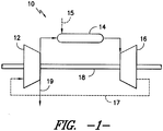
- FIG. 1 illustrates a simplified, block diagram of one embodiment of a gas turbine 10.
- the gas turbine 10 includes a compressor section 12, a combustion section 14, and a turbine section 16.
- the combustion section 14 may include a plurality of combustors 20 (one of which is illustrated in FIG. 2 ) disposed in annular array about the axis of the gas turbine 10.
- the compressor section 12 and turbine section 16 may be coupled by a shaft 18.
- the shaft 18 may be a single shaft or a plurality of shaft segments coupled together to form the shaft 18.
- the gas turbine 10 is generally configured as a closed loop gas turbine, wherein the exhaust gases 17 expelled from the turbine section 16 are re-directed back into the compressor section 12.
- the compressor section 12 may be configured to pressurize the re-circulated exhaust gases and direct such pressurized gases into the combustion section 14.
- the pressurized gases may be mixed with one or more fluids 15 (e.g., fuel and an oxidizer) and burned.
- the hot gases of combustion may then flow from the combustion section 14 to the turbine section 16, wherein energy is extracted to produce work.
- an extraction flow 19 may be removed from within the closed loop.
- the extraction flow 19 may comprise a fluid with a high carbon dioxide content that can be used for carbon capture.
- the exhaust gases 17 may be directed into one or more downstream components of a combined cycle power generation system.
- the exhaust gases 17 expelled from the turbine section 16 may first be directed into a heat recovery steam generator (HRSG) (not shown) configured to produce superheated steam for driving a suitable stream turbine.
- HRSG heat recovery steam generator
- the present subject matter need not be limited to such closed loop gas turbine applications, but may generally be applicable to any suitable turbine application.
- FIGS. 2-5 there is illustrated one embodiment of a combustor 20 in accordance with aspects of the present subject matter.
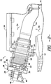
- FIG. 2 illustrates a cross-sectional side view of the combustor 20.
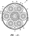
- FIG. 3 illustrates a cross-sectional view of the combustor 20 shown in FIG. 2 taken along line 3-3, particularly illustrating one embodiment of a combustion liner cap 66 of the combustor 20 looking upstream from the combustion chamber 62.
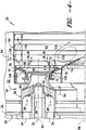
- FIG. 4 illustrates a partial, cross-sectional view of the combustor 20 shown in FIG. 2 .
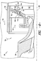
- FIG. 5 illustrates a close-up view of a portion of the combustor 20 shown in FIG. 4 .
- the combustor 20 may include a substantially cylindrical combustion casing 22 secured to a portion of a gas turbine casing 24, such as a compressor discharge casing or a combustion wrapper casing. Additionally, an end cover assembly 26 may be secured to an upstream end of the combustion casing 22.
- the end cover assembly 26 may include an end cover 28 and a plurality of fuel nozzles 30 secured to the end cover 28.
- the fuel nozzles 30 may generally be configured to intake fuel (e.g., gaseous fuel and/or liquid fuel) and other fluids from suitable fluid sources (not shown), mix the fuel and other fluids and distribute the mixture downstream for combustion. For example, as shown in FIG.
- each fuel nozzle 30 may include one or more fluid chambers 32, 34 for receiving one or more fluids, 36, 38 (e.g., fuel, oxidizing fluids, inert gases, air and/or the like), with the fluids 36, 38 being mixed together within the fuel nozzles 30 and expelled therefrom for subsequent combustion.
- fluids e.g., fuel, oxidizing fluids, inert gases, air and/or the like
- the end cover assembly 26 may also include a plurality of tubes, manifolds, associated valves and the like for supplying fluids to the fuel nozzles 30.
- one or more supply tubes 46 may be disposed upstream of the end cover 28 and may extend through the end cover 28 in order to direct fluids 36, 38 into the fuel nozzles 30.
- the combustor 20 may also include a flow sleeve 48 and a combustion liner 50 substantially concentrically arranged within the flow sleeve 48.
- a radial space 52 may generally be defined between the flow sleeve 48 and the combustion liner 50 for directing the compressor discharge fluid 54 (indicated by the arrows) along the outer perimeter of the combustion liner 50.
- the compressor discharge fluid 54 may enter the radial space 52 through the flow sleeve 48 and may be directed along the combustion liner 50 toward the fuel nozzles 30.
- the compressor discharge fluid 54 flowing along the combustion liner 50 may be flow around the upstream end of the liner 50 and may be directed along the outer perimeter of each fuel nozzle 30.
- the combustion liner 50 may generally define a substantially cylindrical combustion chamber 62 ( FIG. 4 ) downstream of the fuel nozzles 30.
- the fluids 36, 38 supplied through the fuel nozzles 30 may be injected into the combustion chamber 62 for combustion therein.
- the hot gases of combustion may then flow from the combustion chamber 62 to a transition piece 64 for directing such gases to a first stage nozzle (not shown) of the turbine section 16 ( FIG. 1 ).
- the disclosed combustor 20 may also include a combustion liner cap 66 coupled to the combustion liner 50 upstream of the combustion chamber 62.
- the liner cap 66 may be configured to be attached to and extend inwardly from the inner perimeter of the combustion liner 50 so to generally define the upstream end of the combustion chamber 62.
- the liner cap 66 may serve to shield or protect any upstream components of the combustor 20 (e.g., the end cover assembly 26) from the hot gases of combustion produced within the combustion chamber 62.
- the liner cap 66 may generally include one or more plates 70, 72 disposed radially outwardly from a center body 74.
- the liner cap 66 may include a nozzle plate 72 configured to extend generally radially between the center body 74 and the combustion liner 50.
- the nozzle plate 70 may include an inner edge 76 coupled to the outer perimeter of the center body 74 and an outer edge 78 coupled to the inner perimeter of the combustion liner 50.
- the nozzle plate 70 may generally be configured to extend from the inner and outer edges 76, 78 so as to receive and/or surround at least a portion of each fuel nozzle 30.
- the nozzle plate 70 may extend axially upstream and radially inwardly relative to a centerline 80 of each fuel nozzle 30 such that a downstream end 82 of each fuel nozzle 30 extends through and is concentrically arranged within a portion of the nozzle plate 70.
- the nozzle plate 70 may extend or otherwise be oriented in any other suitable direction that allows a portion of each fuel nozzle 30 to be received in and/or surrounded by a portion of the nozzle plate 70.
- the nozzle plate 70 may simply be configured to extend radially inwardly relative to the centerline 80 of each nozzle 30.
- the nozzle plate 70 may be configured to be sealed to each of the fuel nozzles 30.
- a suitable seal 84 e.g., a floating collar seal
- the nozzle plate 70 of the liner cap 66 may generally be configured to accommodate any number and/or arrangement of fuel nozzles 30.
- the combustor 20 may include six fuel nozzles 30 disposed in an annular array about a central axis 86 of the combustion liner 50.
- the combustor 20 may include any other suitable number and/or arrangement of fuel nozzles 30.
- the cap liner 66 may also include a plurality of splash plates 72 associated with each fuel nozzle 30.
- the cap liner 66 may include six splash plates 72 disposed adjacent to each fuel nozzle 30.
- Each splash plate 72 may generally be configured to shield the upstream components of the combustor 20 from the fuel and other fluids injected into and burned within the combustion chamber 62.
- the splash plates 72 may be configured to prevent the fluids 36, 38 injected from the fuel nozzles 30 from splashing back and/or impinging onto the nozzle plate 70. Additionally, the splash plates 72 may also prevent the hot gases of combustion produced within the combustor chamber 62 from re-circulating back towards the nozzle plate 70.
- each splash plate 72 may be configured to be attached to the nozzle plate 70 at a location adjacent to each fuel nozzle 30.
- an axially extending portion 92 of each splash plate 72 may be attached to the nozzle plate 70 adjacent to each fuel nozzle 30 such that the splash plates 72 surround and/or encase the downstream ends 82 of the fuel nozzles 30.
- each splash plate 72 may generally be concentrically arranged about the centerline 80 of each fuel nozzle 30.
- the splash plates 72 may be attached to the nozzle plate 70 at any other suitable location and may have any other suitable arrangement relative to the fuel nozzle 30.
- the splash plate 72 may be attached to the nozzle plate 70 using any suitable means known in the art.
- the plates 70, 72 may be welded or brazed together.
- the plates 70, 72 may be attached using a friction fit (e.g., a press-fit or interference-fit) or using suitable mechanical fasteners (e.g., bolts, screws, pins, clips, brackets and the like).
- suitable mechanical fasteners e.g., bolts, screws, pins, clips, brackets and the like.
- the splash plates 72 may be configured to be attached to any other suitable turbine component that permits the splash plates 72 to extend outwardly from the nozzle pate 70 adjacent to each fuel nozzle 30.
- each splash plate 72 may be configured to extend outwardly from the fuel nozzles 30 so as to be spaced apart axially from the nozzle plate 70.
- a portion of each splash plate 72 may be spaced apart from the nozzle plate 70 such that a plenum 94 is defined between the plates 70, 72.
- a plurality of impingement holes 96 may be defined through the nozzle plate 70 to permit the compressor discharge fluid 54 flowing adjacent to an outer face 98 of the nozzle plate 70 to be injected into the plenum 94. The compressor discharge fluid 54 injected through the impingement holes 96 may then flow between the plates 70, 72 and may be expelled along an outer edge 100 of the splash plate 72 into the combustion chamber 62.
- impingement holes 96 may be defined in the nozzle plate 70 for injecting the compressor discharge fluid 54 into the plenum 94. Further, it should be appreciated that the impingement holes 96 may be defined in any suitable arrangement on the nozzle plate 70. For example, in one embodiment, the impingement holes 94 may be defined in one or more annular arrays about the centerline 80 of each fuel nozzle 30. Alternatively, the impingement holes 94 may be randomly scattered around the nozzle plate 70.
- a plurality of fluid conduits 102 may extend between the nozzle plate 70 and the splash plate 72 for injecting a plurality of fluid jets 104 of the compressor discharge fluid 54 through the liner cap 66 and into the combustion chamber 62.
- Each fluid conduit 102 may generally include an upstream end 106 in flow communication with the compressor discharge fluid 54 flowing adjacent to the nozzle plate 70 and a downstream end 108 in flow communication with the combustion chamber 62.
- the upstream end 106 of each fluid conduit 102 may generally be disposed adjacent to the nozzle plate 70 and the downstream end 108 may generally be disposed adjacent to the splash plate 72, such as by configuring the ends 106, 108 of each fluid conduit 102 to be substantially aligned with the plates 70, 72.
- the ends 106, 108 of each fluid conduit 102 may be disposed at any other suitable location, such as by extending axially further upstream of the nozzle plate 70 and/or further downstream of the splash plate 72.
- the fluid conduits 102 may generally comprise any suitable tube, pipe, flow channel and/or any other structure that provides a passageway for the flow of compressor discharge fluid 54 between the nozzle plate 70 and the splash plate 72.
- the fluid conduits 102 may generally comprise tubular members having circular cross-sectional shapes.
- the fluid conduits 102 may have various other suitable cross-sectional shapes, such as rectangular, triangular and/or elliptical cross-sectional shapes.
- each fluid conduit 102 may have a diameter equal to about 51 millimeters (mm) (i.e., about 2 inches).
- each fluid conduits 102 may have any other suitable diameter, such as a diameter of less than about 51 (mm) or greater than about 51 (mm).
- the fluid conduits 102 may be configured to taper in size.
- the upstream end 106 of each fluid conduit 102 may have a diameter that is larger or smaller than the diameter of the downstream end 108 of each fluid conduit 102 such that the conduits 102 converge or diverge, respectively, along their length.
- the particular number and size of the fluid conduits 102 may generally vary depending on the desired amount of compressor discharge fluid 54 to be injected into the combustor chamber 62.
- the number and size of the fluid conduits 102 may be chosen such that less than about 20% of the total amount of compressor discharge fluid 54 flowing into each combustor 20 is directed through the fluid conduits 102, such as from about 5% to about 20% of the total amount of the compressor discharge fluid 54 or from about 10% to about 15% of the total amount of the compressor discharge fluid 54 and all other subranges therebetween.
- the number and size of the fluid conduits 102 may be chosen such that greater than about 20% of the total amount of compressor discharge fluid 54 is directed through the fluid conduits 102.
- the fluid conduits 102 may be attached to and/or between the nozzle and splash plates 70, 72 using any suitable means known in the art.
- a friction fit e.g., a press-fit or interference-fit
- the fluid conduits 102 may be welded between the nozzle plate 70 and splash plate 72 and/or attached to such plates 70, 72 using suitable mechanical fasteners (e.g., bolts, screws, pins, clips, brackets and the like).
- the fluid conduits 102 may generally be positioned in any suitable arrangement between the nozzle and splash plates 70, 72.
- the fluid conduits 102 may generally be positioned between the plates 70, 72 in an annular array about the centerline 80 of each fuel nozzle 30.
- the fluid conduits 102 may be positioned in two or more annular arrays about the centerline 80 of each fuel nozzle 30.
- the fluid conduits 102 may be scattered randomly between the nozzle and splash plates 70, 72.
- the disclosed combustor arrangement may generally provide the combustor 20 improved flame stabilization and increased combustion efficiency.
- the fluid jets 104 of compressor discharge fluid 54 injected into the combustion chamber 62 by the fluid conduits 102 may generally be directed along the outer perimeter of the stream of fluids 36, 38 exiting the fuel nozzles 30.
- recirculation bubbles 110 may be formed adjacent to the inner perimeter of the combustion liner 50 and the center body 74 of the liner cap 66 that restrict the radially outward expansion of the fluids 36, 38, thereby facilitating enhanced mixing of the fluids 36, 38.
- the fluid jets 104 are directed in substantially the same direction as the fluids 36, 38 flowing through the combustion chamber 62, the entrainment of the compressor discharge fluid 54 with the fluids 36, 38 may be decreased, resulting in reduced flame quenching and carbon-dioxide dissociation.
- the fluid conduits 102 may generally be disposed between the nozzle and splash plates 70, 72 so as to be coaxial with the fuel nozzles 30.
- a centerline 112 of each fluid conduit 102 may generally be oriented substantially parallel to the centerline 80 of each fuel nozzle 30.
- the fluid jets 104 injected from the fluid conduits 102 may be directed substantially parallel to the flow of fluids 36, 38 exiting the fuel nozzles 30.
- the fluid conduits 102 may have any other suitable orientation relative to the centerline 80 of each fuel nozzle 30.
- the upstream end 106 of each fluid conduit 102 may generally be radially offset from the downstream end 108 of each fluid conduit 102 such that the fluid jets 104 expelled from the fluid conduits 102 are injected into the combustion chamber 62 at an angle.
- each upstream end 106 is positioned radially inwardly from each downstream end 108 relative to the centerline 80 of each fuel nozzle 30.
- the fluid conduits 102 may generally extend outwardly at a radial angle 114 defined between the centerline 112 of each fluid conduit 102 and the centerline 80 of each fuel nozzle 30.
- the fluid conduits 102 may generally be oriented at any suitable radial angle 114.
- the radial angle 114 may be equal to less than about 30 degrees, such as from about 5 degrees to about 30 degrees or from about 20 degrees to about 30 degrees and all other subranges therebetween.
- each of fluid conduit 102 may be configured to extend radially inwardly between it upstream and downstream ends 106, 08.
- each upstream end 106 of the fluid conduits 102 may be circumferentially offset from each downstream end 108.
- FIG. 7 illustrates a further variation of the embodiments described above, particularly illustrating a portion of a downstream face of the liner cap 66 looking upstream from the combustion chamber 62.
- the circumferential positioning of the upstream ends 106 of each fluid conduit 102 in the nozzle plate 70 is offset from the circumferential positioning of the downstream ends 108 of each fluid conduit in the splash plate 94 by a circumferential angle 116 defined relative to the centerline 80 of each fuel nozzle 30.
- the fluid jets 104 expelled from the fluid conduits 102 may have a circumferential, swirling component to their flow, thereby providing for enhanced mixing of the fluids 36, 38 discharged from the fuel nozzles 30.
- any other suitable fluid from any suitable fluid source may be supplied to and expelled from the fluid conduits 102.
- any suitable fluid from any suitable fluid source may be supplied to and expelled from the fluid conduits 102.
- steam, nitrogen and/or other suitable fluids may be injected into the combustion chamber 62 through the fluid conduits 102.
Abstract
A combustor (20) is disclosed having a combustion liner (50) defining a combustion chamber (62). The combustor (20) may also include a liner cap (66) disposed upstream of the combustion chamber. The liner cap (66) may include a first plate (70) and a second plate (72). Additionally, the combustor may include a fluid conduit extending between the first and second plates. The fluid conduit may be configured to receive fluid flowing adjacent to the first plate and inject the fluid into the combustion chamber.
Description
- The present subject matter relates generally to an apparatus for injecting fluid into a combustion chamber of a combustor and, more particularly, to a combustor including a liner cap having a plurality of fluid conduits for injecting fluid into the combustion chamber.
- Gas turbines typically include a compressor section, a combustion section, and a turbine section. In conventional turbine applications, the compressor section pressurizes air flowing into the gas turbine. The pressurized air discharged from the compressor section flows into the combustion section, which is generally characterized by a plurality of combustors disposed in annular array about the axis of the engine. Specifically, the pressurized air flows along a combustion liner of each combustor and is directed into the combustor's fuel nozzles through one or more inlets or openings defined in the nozzles. The air is then mixed with fuel and the mixture is injected into and burned within the combustion chamber of each combustor. The hot gases of combustion then flow from the combustion section to the turbine section, wherein energy is extracted from the gases to drive the turbine and generate power.
- In other turbine applications, the compressor discharge fluid or working fluid of the gas turbine may comprise a fluid other than air. For example, in oxy-fuel or stoichiometric exhaust gas recirculation (SEGR) applications, the compressor discharge fluid may comprise an oxygen deficient fluid. In such applications, the compressor discharge fluid is primarily utilized to cool turbine components and to dilute the hot gases of combustion produced within the primary flame zone of the combustion chamber. For example, it is known to inject compressor discharge fluid into the combustion chamber through the combustion liner as one or more cross-mixing flows (i.e., perpendicular to the flow of fluids through the combustion liner) in order to promote mixing of the fuel and other fluids expelled from the fuel nozzles. However, these cross-mixing flows can significantly quench the flame contained within the combustion chamber. Such flame quenching can lead to the dissociation of carbon-dioxide within the primary flame zone, thereby significantly decreasing the overall combustion efficiency of the combustor.
- Accordingly, a combustor arrangement that allows compressor discharge fluid to be injected into the combustion chamber without significant flame quenching would be welcomed in the technology.
- Aspects and advantages of the invention will be set forth in part in the following description, or may be obvious from the description, or may be learned through practice of the invention.
- In one aspect, the present resides in a combustor having a combustion liner defining a combustion chamber. The combustor may also include a liner cap disposed upstream of the combustion chamber. The liner cap may include a first plate and a second plate. Additionally, the combustor may include a fluid conduit extending between the first and second plates. The fluid conduit may be configured to receive fluid flowing adjacent to the first plate and inject the fluid into the combustion chamber.
- The combustor may include a fuel nozzle defining a nozzle centerline and additionally, a plurality fluid conduit extending between the first and second plates and spaced apart around the nozzle centerline. The fluid conduits may be configured to receive fluid flowing adjacent to the first plate and inject the fluid into the combustion chamber.
- These and other features, aspects and advantages of the present invention will become better understood with reference to the following description and appended claims. The accompanying drawings, which are incorporated in and constitute a part of this specification, illustrate embodiments of the invention and, together with the description, serve to explain the principles of the invention.
- Embodiments of the present invention will now be described, by way of example only, with reference to the accompanying drawings in which:
-
FIG. 1 illustrates a simplified, block diagram of one embodiment of a gas turbine in accordance with aspects of the present subject matter; -
FIG. 2 illustrates a cross-sectional side view of one embodiment of a combustor suitable for use with the disclosed gas turbine in accordance with aspects of the present subject matter; -
FIG. 3 illustrates a cross-sectional view of the combustor shown inFIG. 2 taken along line 3-3, particularly illustrating one embodiment of a combustion liner cap of the combustor looking upstream from the combustion chamber; -
FIG. 4 illustrates a partial, cross-sectional view of the combustor shown inFIG. 2 ; -
FIG. 5 illustrates a close-up view of a portion of the combustor shown inFIG. 4 ; -
FIG. 6 illustrates a partial, cross-sectional view of another embodiment of the combustor shown inFIGS. 4 and5 ; and -
FIG. 7 illustrates a partial view of another embodiment of a combustion liner cap of the combustor, particularly illustrating the combustion liner cap looking upstream from the combustion chamber. - Reference now will be made in detail to embodiments of the invention, one or more examples of which are illustrated in the drawings. Each example is provided by way of explanation of the invention, not limitation of the invention. In fact, it will be apparent to those skilled in the art that various modifications and variations can be made in the present invention without departing from the scope or spirit of the invention. For instance, features illustrated or described as part of one embodiment can be used with another embodiment to yield a still further embodiment. Thus, it is intended that the present invention covers such modifications and variations as come within the scope of the appended claims and their equivalents.
- In general, the present subject matter is directed to a combustor arrangement for injecting fluid into a combustion chamber of the combustor. In particular, the present subject matter discloses a combustor including a combustion liner cap having a plurality of fluid conduits configured to inject fluid jets of compressor discharge fluid around the outer perimeter of the fuel and other fluids expelled from the combustor's fuel nozzles. Such fluid jets may enable the formation of recirculation bubbles along the inner perimeter of the combustion liner and at a central location within the combustion chamber that restrict the expansion of the stream of fluids exiting the fuel nozzles and promote mixing of such fluids, yielding an improved flame stabilization mechanism. Moreover, since the fluid jets are not directed perpendicularly into the stream of fluids exiting the fuel nozzles, the occurrence of flame quenching may be significantly reduced. As a result, the carbon-dioxide dissociation within the primary flame zone may be decreased, thereby increasing the overall combustion efficiency of the combustor.
- In several embodiments of the present subject matter, the disclosed combustor arrangement may be utilized with closed loop turbine applications having a combustion system (e.g., oxy-fuel combustion systems, near stoichiometric exhaust gas recirculation (SEGR) combustion systems and other low oxygen discharge combustion systems) wherein the fuel supplied through the fuel nozzles is mixed with an oxidizer (e.g., a pure oxygen flow or an oxygen enriched flow) in order to achieve near-stoichiometric combustion. In these turbine applications, the compressor discharge fluid or working fluid of the combustor is typically an oxygen deficient fluid utilized to dilute the gases contained within the primary flame zone. Some examples of an oxygen deficient working fluid may include, for example, a carbon dioxide and steam based mixture and a carbon dioxide and nitrogen based mixture. It has been found by the inventors of the present subject matter that the disclosed combustor arrangement may be particularly advantageous for such turbine applications, as the recirculation bubbles created by the fluid jets may increase the residence time of the oxidizer within the primary flame zone without causing significant flame quenching. As a result, the increased flame stabilization and combustion efficiency typically required with near-stoichiometric applications may be achieved in an efficient and cost-effective manner. However, it should be appreciated that the present subject matter need not be limited to such applications, but may generally be applicable to any suitable turbine application known in the art.
- Referring now to the drawings,
FIG. 1 illustrates a simplified, block diagram of one embodiment of agas turbine 10. Thegas turbine 10 includes acompressor section 12, acombustion section 14, and aturbine section 16. Thecombustion section 14 may include a plurality of combustors 20 (one of which is illustrated inFIG. 2 ) disposed in annular array about the axis of thegas turbine 10. Thecompressor section 12 andturbine section 16 may be coupled by ashaft 18. Theshaft 18 may be a single shaft or a plurality of shaft segments coupled together to form theshaft 18. - As shown, the
gas turbine 10 is generally configured as a closed loop gas turbine, wherein theexhaust gases 17 expelled from theturbine section 16 are re-directed back into thecompressor section 12. Thus, during operation of thegas turbine 10, thecompressor section 12 may be configured to pressurize the re-circulated exhaust gases and direct such pressurized gases into thecombustion section 14. Within each combustor 20 (FIG. 2 ), the pressurized gases may be mixed with one or more fluids 15 (e.g., fuel and an oxidizer) and burned. The hot gases of combustion may then flow from thecombustion section 14 to theturbine section 16, wherein energy is extracted to produce work. Additionally, as shown, anextraction flow 19 may be removed from within the closed loop. For example, theextraction flow 19 may comprise a fluid with a high carbon dioxide content that can be used for carbon capture. - It should be readily appreciated that, prior to the
exhaust gases 17 being re-directed back into thecompressor section 12, theexhaust gases 17 may be directed into one or more downstream components of a combined cycle power generation system. For example, theexhaust gases 17 expelled from theturbine section 16 may first be directed into a heat recovery steam generator (HRSG) (not shown) configured to produce superheated steam for driving a suitable stream turbine. It should also be appreciated that the present subject matter need not be limited to such closed loop gas turbine applications, but may generally be applicable to any suitable turbine application. - Referring to
FIGS. 2-5 , there is illustrated one embodiment of acombustor 20 in accordance with aspects of the present subject matter. In particular,FIG. 2 illustrates a cross-sectional side view of thecombustor 20.FIG. 3 illustrates a cross-sectional view of thecombustor 20 shown inFIG. 2 taken along line 3-3, particularly illustrating one embodiment of acombustion liner cap 66 of thecombustor 20 looking upstream from thecombustion chamber 62.FIG. 4 illustrates a partial, cross-sectional view of thecombustor 20 shown inFIG. 2 . Additionally,FIG. 5 illustrates a close-up view of a portion of thecombustor 20 shown inFIG. 4 . - In general, the
combustor 20 may include a substantiallycylindrical combustion casing 22 secured to a portion of agas turbine casing 24, such as a compressor discharge casing or a combustion wrapper casing. Additionally, anend cover assembly 26 may be secured to an upstream end of thecombustion casing 22. Theend cover assembly 26 may include anend cover 28 and a plurality offuel nozzles 30 secured to theend cover 28. The fuel nozzles 30 may generally be configured to intake fuel (e.g., gaseous fuel and/or liquid fuel) and other fluids from suitable fluid sources (not shown), mix the fuel and other fluids and distribute the mixture downstream for combustion. For example, as shown inFIG. 4 , eachfuel nozzle 30 may include one or morefluid chambers fluids fuel nozzles 30 and expelled therefrom for subsequent combustion. - It should be appreciated that the
end cover assembly 26 may also include a plurality of tubes, manifolds, associated valves and the like for supplying fluids to thefuel nozzles 30. For instance, as shown inFIG. 2 , one ormore supply tubes 46 may be disposed upstream of theend cover 28 and may extend through theend cover 28 in order to directfluids fuel nozzles 30. - The
combustor 20 may also include aflow sleeve 48 and acombustion liner 50 substantially concentrically arranged within theflow sleeve 48. As such, aradial space 52 may generally be defined between theflow sleeve 48 and thecombustion liner 50 for directing the compressor discharge fluid 54 (indicated by the arrows) along the outer perimeter of thecombustion liner 50. For example, thecompressor discharge fluid 54 may enter theradial space 52 through theflow sleeve 48 and may be directed along thecombustion liner 50 toward thefuel nozzles 30. Thus, as shown inFIG. 4 , thecompressor discharge fluid 54 flowing along thecombustion liner 50 may be flow around the upstream end of theliner 50 and may be directed along the outer perimeter of eachfuel nozzle 30. Thecombustion liner 50 may generally define a substantially cylindrical combustion chamber 62 (FIG. 4 ) downstream of thefuel nozzles 30. As is generally known, thefluids fuel nozzles 30 may be injected into thecombustion chamber 62 for combustion therein. The hot gases of combustion may then flow from thecombustion chamber 62 to atransition piece 64 for directing such gases to a first stage nozzle (not shown) of the turbine section 16 (FIG. 1 ). - The disclosed
combustor 20 may also include acombustion liner cap 66 coupled to thecombustion liner 50 upstream of thecombustion chamber 62. For example, in several embodiments, theliner cap 66 may be configured to be attached to and extend inwardly from the inner perimeter of thecombustion liner 50 so to generally define the upstream end of thecombustion chamber 62. As such, theliner cap 66 may serve to shield or protect any upstream components of the combustor 20 (e.g., the end cover assembly 26) from the hot gases of combustion produced within thecombustion chamber 62. - In several embodiments, the
liner cap 66 may generally include one ormore plates center body 74. For example, theliner cap 66 may include anozzle plate 72 configured to extend generally radially between thecenter body 74 and thecombustion liner 50. For example, as shown in the illustrated embodiment, thenozzle plate 70 may include aninner edge 76 coupled to the outer perimeter of thecenter body 74 and anouter edge 78 coupled to the inner perimeter of thecombustion liner 50. Additionally, thenozzle plate 70 may generally be configured to extend from the inner andouter edges fuel nozzle 30. Thus, as shown inFIG. 4 , in one embodiment, thenozzle plate 70 may extend axially upstream and radially inwardly relative to acenterline 80 of eachfuel nozzle 30 such that adownstream end 82 of eachfuel nozzle 30 extends through and is concentrically arranged within a portion of thenozzle plate 70. In alternative embodiments, thenozzle plate 70 may extend or otherwise be oriented in any other suitable direction that allows a portion of eachfuel nozzle 30 to be received in and/or surrounded by a portion of thenozzle plate 70. For instance, thenozzle plate 70 may simply be configured to extend radially inwardly relative to thecenterline 80 of eachnozzle 30. Moreover, in one embodiment, thenozzle plate 70 may be configured to be sealed to each of thefuel nozzles 30. For example, as shown inFIGS. 4 and5 , a suitable seal 84 (e.g., a floating collar seal) may be disposed between a portion of thenozzle plate 70 and a portion of eachfuel nozzle 30. - It should be appreciated that the
nozzle plate 70 of theliner cap 66 may generally be configured to accommodate any number and/or arrangement offuel nozzles 30. For example, as shown inFIG. 3 , thecombustor 20 may include sixfuel nozzles 30 disposed in an annular array about acentral axis 86 of thecombustion liner 50. However, in other embodiments, thecombustor 20 may include any other suitable number and/or arrangement offuel nozzles 30. - Moreover, the
cap liner 66 may also include a plurality ofsplash plates 72 associated with eachfuel nozzle 30. For example, as shown inFIG. 3 , thecap liner 66 may include sixsplash plates 72 disposed adjacent to eachfuel nozzle 30. Eachsplash plate 72 may generally be configured to shield the upstream components of the combustor 20 from the fuel and other fluids injected into and burned within thecombustion chamber 62. For example, in the illustrated embodiment, thesplash plates 72 may be configured to prevent thefluids fuel nozzles 30 from splashing back and/or impinging onto thenozzle plate 70. Additionally, thesplash plates 72 may also prevent the hot gases of combustion produced within thecombustor chamber 62 from re-circulating back towards thenozzle plate 70. - In several embodiments, each
splash plate 72 may be configured to be attached to thenozzle plate 70 at a location adjacent to eachfuel nozzle 30. For example, as particularly shown inFIGS. 4 and5 , in one embodiment, anaxially extending portion 92 of eachsplash plate 72 may be attached to thenozzle plate 70 adjacent to eachfuel nozzle 30 such that thesplash plates 72 surround and/or encase the downstream ends 82 of thefuel nozzles 30. As such, eachsplash plate 72 may generally be concentrically arranged about thecenterline 80 of eachfuel nozzle 30. However, in other embodiments, thesplash plates 72 may be attached to thenozzle plate 70 at any other suitable location and may have any other suitable arrangement relative to thefuel nozzle 30. - It should be appreciated that the
splash plate 72 may be attached to thenozzle plate 70 using any suitable means known in the art. For instance, in one embodiment, theplates plates splash plates 72 may be configured to be attached to any other suitable turbine component that permits thesplash plates 72 to extend outwardly from thenozzle pate 70 adjacent to eachfuel nozzle 30. - Additionally, in several embodiments, each
splash plate 72 may be configured to extend outwardly from thefuel nozzles 30 so as to be spaced apart axially from thenozzle plate 70. For example, as particularly shown inFIG. 5 , a portion of eachsplash plate 72 may be spaced apart from thenozzle plate 70 such that aplenum 94 is defined between theplates nozzle plate 70 to permit thecompressor discharge fluid 54 flowing adjacent to anouter face 98 of thenozzle plate 70 to be injected into theplenum 94. Thecompressor discharge fluid 54 injected through the impingement holes 96 may then flow between theplates outer edge 100 of thesplash plate 72 into thecombustion chamber 62. - It should be appreciated that any suitable number of impingement holes 96 may be defined in the
nozzle plate 70 for injecting thecompressor discharge fluid 54 into theplenum 94. Further, it should be appreciated that the impingement holes 96 may be defined in any suitable arrangement on thenozzle plate 70. For example, in one embodiment, the impingement holes 94 may be defined in one or more annular arrays about thecenterline 80 of eachfuel nozzle 30. Alternatively, the impingement holes 94 may be randomly scattered around thenozzle plate 70. - Moreover, in several embodiments of the present subject matter, a plurality of
fluid conduits 102 may extend between thenozzle plate 70 and thesplash plate 72 for injecting a plurality offluid jets 104 of thecompressor discharge fluid 54 through theliner cap 66 and into thecombustion chamber 62. Eachfluid conduit 102 may generally include anupstream end 106 in flow communication with thecompressor discharge fluid 54 flowing adjacent to thenozzle plate 70 and adownstream end 108 in flow communication with thecombustion chamber 62. Thus, as shown inFIGS. 4 and5 , in one embodiment, theupstream end 106 of eachfluid conduit 102 may generally be disposed adjacent to thenozzle plate 70 and thedownstream end 108 may generally be disposed adjacent to thesplash plate 72, such as by configuring theends fluid conduit 102 to be substantially aligned with theplates ends fluid conduit 102 may be disposed at any other suitable location, such as by extending axially further upstream of thenozzle plate 70 and/or further downstream of thesplash plate 72. - It should be appreciated that the
fluid conduits 102 may generally comprise any suitable tube, pipe, flow channel and/or any other structure that provides a passageway for the flow ofcompressor discharge fluid 54 between thenozzle plate 70 and thesplash plate 72. For example, as shown inFIG. 3 , in one embodiment, thefluid conduits 102 may generally comprise tubular members having circular cross-sectional shapes. However, in other embodiments, thefluid conduits 102 may have various other suitable cross-sectional shapes, such as rectangular, triangular and/or elliptical cross-sectional shapes. Additionally, in one embodiment, eachfluid conduit 102 may have a diameter equal to about 51 millimeters (mm) (i.e., about 2 inches). In other embodiments, eachfluid conduits 102 may have any other suitable diameter, such as a diameter of less than about 51 (mm) or greater than about 51 (mm). Moreover, in further embodiments, thefluid conduits 102 may be configured to taper in size. For example, theupstream end 106 of eachfluid conduit 102 may have a diameter that is larger or smaller than the diameter of thedownstream end 108 of eachfluid conduit 102 such that theconduits 102 converge or diverge, respectively, along their length. - Further, in several embodiments, the particular number and size of the
fluid conduits 102 may generally vary depending on the desired amount ofcompressor discharge fluid 54 to be injected into thecombustor chamber 62. For example, in one embodiment, the number and size of thefluid conduits 102 may be chosen such that less than about 20% of the total amount ofcompressor discharge fluid 54 flowing into each combustor 20 is directed through thefluid conduits 102, such as from about 5% to about 20% of the total amount of thecompressor discharge fluid 54 or from about 10% to about 15% of the total amount of thecompressor discharge fluid 54 and all other subranges therebetween. However, in an alternative embodiment, the number and size of thefluid conduits 102 may be chosen such that greater than about 20% of the total amount ofcompressor discharge fluid 54 is directed through thefluid conduits 102. - Additionally, in several embodiments, the
fluid conduits 102 may be attached to and/or between the nozzle andsplash plates fluid conduit 102 to theplates fluid conduits 102 may be welded between thenozzle plate 70 andsplash plate 72 and/or attached tosuch plates - Moreover, the
fluid conduits 102 may generally be positioned in any suitable arrangement between the nozzle andsplash plates FIG. 3 , in one embodiment, thefluid conduits 102 may generally be positioned between theplates centerline 80 of eachfuel nozzle 30. In others embodiments, thefluid conduits 102 may be positioned in two or more annular arrays about thecenterline 80 of eachfuel nozzle 30. Alternatively, thefluid conduits 102 may be scattered randomly between the nozzle andsplash plates - As indicated above, the disclosed combustor arrangement may generally provide the
combustor 20 improved flame stabilization and increased combustion efficiency. For example, as particularly shown inFIG. 4 , thefluid jets 104 ofcompressor discharge fluid 54 injected into thecombustion chamber 62 by thefluid conduits 102 may generally be directed along the outer perimeter of the stream offluids fuel nozzles 30. As such, recirculation bubbles 110 may be formed adjacent to the inner perimeter of thecombustion liner 50 and thecenter body 74 of theliner cap 66 that restrict the radially outward expansion of thefluids fluids fluid jets 104 are directed in substantially the same direction as thefluids combustion chamber 62, the entrainment of thecompressor discharge fluid 54 with thefluids - Thus, in several embodiments of the present subject matter, the
fluid conduits 102 may generally be disposed between the nozzle andsplash plates fuel nozzles 30. For example, as shown inFIG. 5 , acenterline 112 of eachfluid conduit 102 may generally be oriented substantially parallel to thecenterline 80 of eachfuel nozzle 30. As such, thefluid jets 104 injected from thefluid conduits 102 may be directed substantially parallel to the flow offluids fuel nozzles 30. - In other embodiments, the
fluid conduits 102 may have any other suitable orientation relative to thecenterline 80 of eachfuel nozzle 30. For example, as shown inFIG. 6 , theupstream end 106 of eachfluid conduit 102 may generally be radially offset from thedownstream end 108 of eachfluid conduit 102 such that thefluid jets 104 expelled from thefluid conduits 102 are injected into thecombustion chamber 62 at an angle. Specifically, in the illustrated embodiment, eachupstream end 106 is positioned radially inwardly from eachdownstream end 108 relative to thecenterline 80 of eachfuel nozzle 30. As such, thefluid conduits 102 may generally extend outwardly at aradial angle 114 defined between thecenterline 112 of eachfluid conduit 102 and thecenterline 80 of eachfuel nozzle 30. - It should be appreciated that the
fluid conduits 102 may generally be oriented at any suitableradial angle 114. However, in one embodiment, theradial angle 114 may be equal to less than about 30 degrees, such as from about 5 degrees to about 30 degrees or from about 20 degrees to about 30 degrees and all other subranges therebetween. It should also be appreciated that, in an alternative embodiment, each offluid conduit 102 may be configured to extend radially inwardly between it upstream and downstream ends 106, 08. - Moreover, in a further embodiment, each
upstream end 106 of thefluid conduits 102 may be circumferentially offset from eachdownstream end 108. For example,FIG. 7 illustrates a further variation of the embodiments described above, particularly illustrating a portion of a downstream face of theliner cap 66 looking upstream from thecombustion chamber 62. As shown, the circumferential positioning of the upstream ends 106 of eachfluid conduit 102 in thenozzle plate 70 is offset from the circumferential positioning of the downstream ends 108 of each fluid conduit in thesplash plate 94 by acircumferential angle 116 defined relative to thecenterline 80 of eachfuel nozzle 30. As such, thefluid jets 104 expelled from thefluid conduits 102 may have a circumferential, swirling component to their flow, thereby providing for enhanced mixing of thefluids fuel nozzles 30. - It should be appreciated that, although the present subject matter has been generally described as using
compressor discharge fluid 54 for injection into thecombustion chamber 62, any other suitable fluid from any suitable fluid source may be supplied to and expelled from thefluid conduits 102. For example, steam, nitrogen and/or other suitable fluids may be injected into thecombustion chamber 62 through thefluid conduits 102. - This written description uses examples to disclose the invention, including the best mode, and also to enable any person skilled in the art to practice the invention, including making and using any devices or systems and performing any incorporated methods. The patentable scope of the invention is defined by the claims, and may include other examples that occur to those skilled in the art. Such other examples are intended to be within the scope of the claims if they include structural elements that do not differ from the literal language of the claims, or if they include equivalent structural elements with insubstantial differences from the literal languages of the claims.
Claims (11)
- A combustor (20) comprising:a combustion liner (50) defining a combustion chamber (62);a liner cap (66) disposed upstream of said combustion chamber (62), said liner cap (66) including a first plate (70) and a second plate (72; anda fluid conduit extending between said first and second plates, said fluid conduit being configured to receive fluid flowing adjacent to said first plate (70) and inject the fluid into said combustion chamber (62).
- The combustor of claim 1, further comprising a plurality of fluid conduits extending between said first (70) and second (72) plates, each of said plurality of fluid conduits being configured to receive the fluid flowing adjacent to said first plate (70) and inject the fluid into said combustion chamber (62).
- The combustor of claim 1 or 2, further comprising a fuel nozzle (30) extending through at least a portion of said liner cap (66), said fuel nozzle (30) defining a nozzle centerline (80).
- The combustor of claim 3, wherein each said fluid conduit, or each of said plurality of fluid conduits, is oriented substantially parallel to said nozzle centerline (80).
- The combustor of claim 3, wherein each said fluid conduit, or each of said plurality of fluid conduits, is angled relative to said nozzle centerline (80).
- The combustor of claim 5, wherein each said fluid conduit, or each of said plurality of fluid conduits, extends radially outwardly relative to said nozzle centerline (80) from said first plate (70) to said second plate (72).
- The combustor of claim 5, wherein each said fluid conduit, or each of said plurality of fluid conduits, is angled relative to said nozzle centerline (80) at an angle equal to less than about 30 degrees.
- The combustor of any preceding claim, wherein each said fluid conduit, or each of said plurality of fluid conduits, includes a first end disposed adjacent to said first plate (70) and a second end disposed adjacent to said second plate (72).
- The combustor of claim 8, wherein said first end is circumferentially offset from said second end.
- The combustor of any preceding claim, wherein said second plate is spaced apart from said first plate (70) such that a plenum (94) is defined between said first (70) and second (72) plates, said first plate (70) defining a plurality of impingement holes (96) for injecting a portion of the fluid into said plenum (94).
- The combustor of any of claims 3 to 10 when dependent on claim 2, further comprising a fuel nozzle (30) extending through at least a portion of said liner cap (66), wherein said plurality of fluid conduits is arranged in an annular array around said fuel nozzle (30).
Applications Claiming Priority (1)
| Application Number | Priority Date | Filing Date | Title |
|---|---|---|---|
| US13/031,314 US20120210717A1 (en) | 2011-02-21 | 2011-02-21 | Apparatus for injecting fluid into a combustion chamber of a combustor |
Publications (1)
| Publication Number | Publication Date |
|---|---|
| EP2489934A2 true EP2489934A2 (en) | 2012-08-22 |
Family
ID=45655884
Family Applications (1)
| Application Number | Title | Priority Date | Filing Date |
|---|---|---|---|
| EP12155666A Withdrawn EP2489934A2 (en) | 2011-02-21 | 2012-02-15 | Apparatus for injecting fluid into a combustion chamber of a combustor |
Country Status (3)
| Country | Link |
|---|---|
| US (1) | US20120210717A1 (en) |
| EP (1) | EP2489934A2 (en) |
| CN (1) | CN102679341A (en) |
Cited By (1)
| Publication number | Priority date | Publication date | Assignee | Title |
|---|---|---|---|---|
| WO2016063222A1 (en) * | 2014-10-20 | 2016-04-28 | A.S.EN. ANSALDO SVILUPPO ENERGIA S.r.l. | Gas turbine unit with multifluid fuel supply and method of supplying a burner of a gas turbine unit |
Families Citing this family (6)
| Publication number | Priority date | Publication date | Assignee | Title |
|---|---|---|---|---|
| US20140182305A1 (en) * | 2012-12-28 | 2014-07-03 | Exxonmobil Upstream Research Company | System and method for a turbine combustor |
| US9631815B2 (en) * | 2012-12-28 | 2017-04-25 | General Electric Company | System and method for a turbine combustor |
| US9803865B2 (en) * | 2012-12-28 | 2017-10-31 | General Electric Company | System and method for a turbine combustor |
| EP3008390A1 (en) * | 2013-10-31 | 2016-04-20 | Siemens Aktiengesellschaft | Gas turbine burner hub with pilot burner |
| US10731860B2 (en) * | 2015-02-05 | 2020-08-04 | Delavan, Inc. | Air shrouds with air wipes |
| US10781715B2 (en) * | 2015-12-21 | 2020-09-22 | Raytheon Technologies Corporation | Impingement cooling baffle |
Family Cites Families (26)
| Publication number | Priority date | Publication date | Assignee | Title |
|---|---|---|---|---|
| US2942790A (en) * | 1959-01-23 | 1960-06-28 | Gen Electric | Air-atomizing liquid spray nozzle |
| US4198815A (en) * | 1975-12-24 | 1980-04-22 | General Electric Company | Central injection fuel carburetor |
| US4100733A (en) * | 1976-10-04 | 1978-07-18 | United Technologies Corporation | Premix combustor |
| US4262482A (en) * | 1977-11-17 | 1981-04-21 | Roffe Gerald A | Apparatus for the premixed gas phase combustion of liquid fuels |
| EP0153842B1 (en) * | 1984-02-29 | 1988-07-27 | LUCAS INDUSTRIES public limited company | Combustion equipment |
| FR2572463B1 (en) * | 1984-10-30 | 1989-01-20 | Snecma | INJECTION SYSTEM WITH VARIABLE GEOMETRY. |
| GB9112324D0 (en) * | 1991-06-07 | 1991-07-24 | Rolls Royce Plc | Gas turbine engine combustor |
| US5235814A (en) * | 1991-08-01 | 1993-08-17 | General Electric Company | Flashback resistant fuel staged premixed combustor |
| US5444982A (en) * | 1994-01-12 | 1995-08-29 | General Electric Company | Cyclonic prechamber with a centerbody |
| GB2287310B (en) * | 1994-03-01 | 1997-12-03 | Rolls Royce Plc | Gas turbine engine combustor heatshield |
| JPH08270950A (en) * | 1995-02-01 | 1996-10-18 | Mitsubishi Heavy Ind Ltd | Gas turbine combustor |
| US5930999A (en) * | 1997-07-23 | 1999-08-03 | General Electric Company | Fuel injector and multi-swirler carburetor assembly |
| FR2774152B1 (en) * | 1998-01-28 | 2000-03-24 | Inst Francais Du Petrole | COMBUSTION CHAMBER OF GAS TURBINE OPERATING ON LIQUID FUEL |
| US6298667B1 (en) * | 2000-06-22 | 2001-10-09 | General Electric Company | Modular combustor dome |
| US6536216B2 (en) * | 2000-12-08 | 2003-03-25 | General Electric Company | Apparatus for injecting fuel into gas turbine engines |
| US6546733B2 (en) * | 2001-06-28 | 2003-04-15 | General Electric Company | Methods and systems for cooling gas turbine engine combustors |
| US7143583B2 (en) * | 2002-08-22 | 2006-12-05 | Hitachi, Ltd. | Gas turbine combustor, combustion method of the gas turbine combustor, and method of remodeling a gas turbine combustor |
| US6851263B2 (en) * | 2002-10-29 | 2005-02-08 | General Electric Company | Liner for a gas turbine engine combustor having trapped vortex cavity |
| US7007486B2 (en) * | 2003-03-26 | 2006-03-07 | The Boeing Company | Apparatus and method for selecting a flow mixture |
| US7017329B2 (en) * | 2003-10-10 | 2006-03-28 | United Technologies Corporation | Method and apparatus for mixing substances |
| US7469544B2 (en) * | 2003-10-10 | 2008-12-30 | Pratt & Whitney Rocketdyne | Method and apparatus for injecting a fuel into a combustor assembly |
| US7010921B2 (en) * | 2004-06-01 | 2006-03-14 | General Electric Company | Method and apparatus for cooling combustor liner and transition piece of a gas turbine |
| US7007478B2 (en) * | 2004-06-30 | 2006-03-07 | General Electric Company | Multi-venturi tube fuel injector for a gas turbine combustor |
| US6983600B1 (en) * | 2004-06-30 | 2006-01-10 | General Electric Company | Multi-venturi tube fuel injector for gas turbine combustors |
| US7003958B2 (en) * | 2004-06-30 | 2006-02-28 | General Electric Company | Multi-sided diffuser for a venturi in a fuel injector for a gas turbine |
| US20090223227A1 (en) * | 2008-03-05 | 2009-09-10 | General Electric Company | Combustion cap with crown mixing holes |
-
2011
- 2011-02-21 US US13/031,314 patent/US20120210717A1/en not_active Abandoned
-
2012
- 2012-02-15 EP EP12155666A patent/EP2489934A2/en not_active Withdrawn
- 2012-02-21 CN CN201210050738XA patent/CN102679341A/en active Pending
Non-Patent Citations (1)
| Title |
|---|
| None |
Cited By (1)
| Publication number | Priority date | Publication date | Assignee | Title |
|---|---|---|---|---|
| WO2016063222A1 (en) * | 2014-10-20 | 2016-04-28 | A.S.EN. ANSALDO SVILUPPO ENERGIA S.r.l. | Gas turbine unit with multifluid fuel supply and method of supplying a burner of a gas turbine unit |
Also Published As
| Publication number | Publication date |
|---|---|
| US20120210717A1 (en) | 2012-08-23 |
| CN102679341A (en) | 2012-09-19 |
Similar Documents
| Publication | Publication Date | Title |
|---|---|---|
| US11187415B2 (en) | Fuel injection assemblies for axial fuel staging in gas turbine combustors | |
| CN108870442B (en) | Dual fuel injector and method of use in a gas turbine combustor | |
| EP2489934A2 (en) | Apparatus for injecting fluid into a combustion chamber of a combustor | |
| JP6138584B2 (en) | Fuel injection assembly for use in a turbine engine and method of assembling the same | |
| US9534790B2 (en) | Fuel injector for supplying fuel to a combustor | |
| US9133722B2 (en) | Transition duct with late injection in turbine system | |
| US9599343B2 (en) | Fuel nozzle for use in a turbine engine and method of assembly | |
| JP7337497B2 (en) | Axial fuel staging system for gas turbine combustors | |
| US10655858B2 (en) | Cooling of liquid fuel cartridge in gas turbine combustor head end | |
| JP7242277B2 (en) | Thimble assembly for introducing cross-flow into the secondary combustion zone | |
| CN103363549A (en) | Combustor and method for supplying fuel to combustor | |
| US20120204571A1 (en) | Combustor and method for introducing a secondary fluid into a fuel nozzle | |
| EP3875856B1 (en) | Integrated combustor nozzle with fluid mixing assembly | |
| EP3845811B1 (en) | Gas turbine combustor with fluid mixing apparatus using fuel and high- and low-pressure air streams | |
| EP2587159B1 (en) | Fuel injection assembly for use in turbine engines and method of assembling same | |
| US9677766B2 (en) | Fuel nozzle for use in a turbine engine and method of assembly | |
| EP2515041A2 (en) | Fuel Nozzle And Method For Operating A Combustor | |
| US9010083B2 (en) | Apparatus for mixing fuel in a gas turbine | |
| EP2626632A2 (en) | Fuel injection assembly for use in turbine engines and method of assembling same |
Legal Events
| Date | Code | Title | Description |
|---|---|---|---|
| PUAI | Public reference made under article 153(3) epc to a published international application that has entered the european phase |
Free format text: ORIGINAL CODE: 0009012 |
|
| AK | Designated contracting states |
Kind code of ref document: A2 Designated state(s): AL AT BE BG CH CY CZ DE DK EE ES FI FR GB GR HR HU IE IS IT LI LT LU LV MC MK MT NL NO PL PT RO RS SE SI SK SM TR |
|
| AX | Request for extension of the european patent |
Extension state: BA ME |
|
| STAA | Information on the status of an ep patent application or granted ep patent |
Free format text: STATUS: THE APPLICATION IS DEEMED TO BE WITHDRAWN |
|
| 18D | Application deemed to be withdrawn |
Effective date: 20140902 |