EP2489922B1 - Verfahren zum Einführen/Herausnehmen eines Instruments in einem Behälter - Google Patents
Verfahren zum Einführen/Herausnehmen eines Instruments in einem Behälter Download PDFInfo
- Publication number
- EP2489922B1 EP2489922B1 EP12154584.2A EP12154584A EP2489922B1 EP 2489922 B1 EP2489922 B1 EP 2489922B1 EP 12154584 A EP12154584 A EP 12154584A EP 2489922 B1 EP2489922 B1 EP 2489922B1
- Authority
- EP
- European Patent Office
- Prior art keywords
- shuttle
- guide
- tank
- recess
- instrument
- Prior art date
- Legal status (The legal status is an assumption and is not a legal conclusion. Google has not performed a legal analysis and makes no representation as to the accuracy of the status listed.)
- Active
Links
- 238000000034 method Methods 0.000 title claims description 18
- 239000011261 inert gas Substances 0.000 claims description 24
- 239000007789 gas Substances 0.000 claims description 15
- IJGRMHOSHXDMSA-UHFFFAOYSA-N Atomic nitrogen Chemical compound N#N IJGRMHOSHXDMSA-UHFFFAOYSA-N 0.000 claims description 14
- 239000003949 liquefied natural gas Substances 0.000 claims description 14
- VNWKTOKETHGBQD-UHFFFAOYSA-N methane Chemical compound C VNWKTOKETHGBQD-UHFFFAOYSA-N 0.000 claims description 10
- 239000012530 fluid Substances 0.000 claims description 9
- 229910052757 nitrogen Inorganic materials 0.000 claims description 7
- 238000002347 injection Methods 0.000 claims description 5
- 239000007924 injection Substances 0.000 claims description 5
- 239000003345 natural gas Substances 0.000 claims description 5
- 238000006073 displacement reaction Methods 0.000 claims description 2
- 238000007789 sealing Methods 0.000 description 7
- 230000008020 evaporation Effects 0.000 description 4
- 238000001704 evaporation Methods 0.000 description 4
- 238000012423 maintenance Methods 0.000 description 4
- 239000007788 liquid Substances 0.000 description 3
- 238000003860 storage Methods 0.000 description 3
- 235000021183 entrée Nutrition 0.000 description 2
- 238000004519 manufacturing process Methods 0.000 description 2
- 239000003550 marker Substances 0.000 description 2
- 239000000523 sample Substances 0.000 description 2
- 239000000243 solution Substances 0.000 description 2
- 238000003466 welding Methods 0.000 description 2
- 238000001514 detection method Methods 0.000 description 1
- 230000001681 protective effect Effects 0.000 description 1
- 230000000007 visual effect Effects 0.000 description 1
Images

Classifications
-
- F—MECHANICAL ENGINEERING; LIGHTING; HEATING; WEAPONS; BLASTING
- F17—STORING OR DISTRIBUTING GASES OR LIQUIDS
- F17C—VESSELS FOR CONTAINING OR STORING COMPRESSED, LIQUEFIED OR SOLIDIFIED GASES; FIXED-CAPACITY GAS-HOLDERS; FILLING VESSELS WITH, OR DISCHARGING FROM VESSELS, COMPRESSED, LIQUEFIED, OR SOLIDIFIED GASES
- F17C13/00—Details of vessels or of the filling or discharging of vessels
- F17C13/02—Special adaptations of indicating, measuring, or monitoring equipment
-
- F—MECHANICAL ENGINEERING; LIGHTING; HEATING; WEAPONS; BLASTING
- F17—STORING OR DISTRIBUTING GASES OR LIQUIDS
- F17C—VESSELS FOR CONTAINING OR STORING COMPRESSED, LIQUEFIED OR SOLIDIFIED GASES; FIXED-CAPACITY GAS-HOLDERS; FILLING VESSELS WITH, OR DISCHARGING FROM VESSELS, COMPRESSED, LIQUEFIED, OR SOLIDIFIED GASES
- F17C13/00—Details of vessels or of the filling or discharging of vessels
-
- F—MECHANICAL ENGINEERING; LIGHTING; HEATING; WEAPONS; BLASTING
- F17—STORING OR DISTRIBUTING GASES OR LIQUIDS
- F17C—VESSELS FOR CONTAINING OR STORING COMPRESSED, LIQUEFIED OR SOLIDIFIED GASES; FIXED-CAPACITY GAS-HOLDERS; FILLING VESSELS WITH, OR DISCHARGING FROM VESSELS, COMPRESSED, LIQUEFIED, OR SOLIDIFIED GASES
- F17C2205/00—Vessel construction, in particular mounting arrangements, attachments or identifications means
- F17C2205/03—Fluid connections, filters, valves, closure means or other attachments
- F17C2205/0302—Fittings, valves, filters, or components in connection with the gas storage device
-
- F—MECHANICAL ENGINEERING; LIGHTING; HEATING; WEAPONS; BLASTING
- F17—STORING OR DISTRIBUTING GASES OR LIQUIDS
- F17C—VESSELS FOR CONTAINING OR STORING COMPRESSED, LIQUEFIED OR SOLIDIFIED GASES; FIXED-CAPACITY GAS-HOLDERS; FILLING VESSELS WITH, OR DISCHARGING FROM VESSELS, COMPRESSED, LIQUEFIED, OR SOLIDIFIED GASES
- F17C2221/00—Handled fluid, in particular type of fluid
- F17C2221/03—Mixtures
- F17C2221/032—Hydrocarbons
- F17C2221/033—Methane, e.g. natural gas, CNG, LNG, GNL, GNC, PLNG
-
- F—MECHANICAL ENGINEERING; LIGHTING; HEATING; WEAPONS; BLASTING
- F17—STORING OR DISTRIBUTING GASES OR LIQUIDS
- F17C—VESSELS FOR CONTAINING OR STORING COMPRESSED, LIQUEFIED OR SOLIDIFIED GASES; FIXED-CAPACITY GAS-HOLDERS; FILLING VESSELS WITH, OR DISCHARGING FROM VESSELS, COMPRESSED, LIQUEFIED, OR SOLIDIFIED GASES
- F17C2223/00—Handled fluid before transfer, i.e. state of fluid when stored in the vessel or before transfer from the vessel
- F17C2223/01—Handled fluid before transfer, i.e. state of fluid when stored in the vessel or before transfer from the vessel characterised by the phase
- F17C2223/0146—Two-phase
- F17C2223/0153—Liquefied gas, e.g. LPG, GPL
- F17C2223/0161—Liquefied gas, e.g. LPG, GPL cryogenic, e.g. LNG, GNL, PLNG
-
- F—MECHANICAL ENGINEERING; LIGHTING; HEATING; WEAPONS; BLASTING
- F17—STORING OR DISTRIBUTING GASES OR LIQUIDS
- F17C—VESSELS FOR CONTAINING OR STORING COMPRESSED, LIQUEFIED OR SOLIDIFIED GASES; FIXED-CAPACITY GAS-HOLDERS; FILLING VESSELS WITH, OR DISCHARGING FROM VESSELS, COMPRESSED, LIQUEFIED, OR SOLIDIFIED GASES
- F17C2223/00—Handled fluid before transfer, i.e. state of fluid when stored in the vessel or before transfer from the vessel
- F17C2223/03—Handled fluid before transfer, i.e. state of fluid when stored in the vessel or before transfer from the vessel characterised by the pressure level
- F17C2223/033—Small pressure, e.g. for liquefied gas
-
- F—MECHANICAL ENGINEERING; LIGHTING; HEATING; WEAPONS; BLASTING
- F17—STORING OR DISTRIBUTING GASES OR LIQUIDS
- F17C—VESSELS FOR CONTAINING OR STORING COMPRESSED, LIQUEFIED OR SOLIDIFIED GASES; FIXED-CAPACITY GAS-HOLDERS; FILLING VESSELS WITH, OR DISCHARGING FROM VESSELS, COMPRESSED, LIQUEFIED, OR SOLIDIFIED GASES
- F17C2250/00—Accessories; Control means; Indicating, measuring or monitoring of parameters
- F17C2250/03—Control means
- F17C2250/038—Control means using cameras
-
- F—MECHANICAL ENGINEERING; LIGHTING; HEATING; WEAPONS; BLASTING
- F17—STORING OR DISTRIBUTING GASES OR LIQUIDS
- F17C—VESSELS FOR CONTAINING OR STORING COMPRESSED, LIQUEFIED OR SOLIDIFIED GASES; FIXED-CAPACITY GAS-HOLDERS; FILLING VESSELS WITH, OR DISCHARGING FROM VESSELS, COMPRESSED, LIQUEFIED, OR SOLIDIFIED GASES
- F17C2250/00—Accessories; Control means; Indicating, measuring or monitoring of parameters
- F17C2250/04—Indicating or measuring of parameters as input values
- F17C2250/0404—Parameters indicated or measured
- F17C2250/0408—Level of content in the vessel
-
- F—MECHANICAL ENGINEERING; LIGHTING; HEATING; WEAPONS; BLASTING
- F17—STORING OR DISTRIBUTING GASES OR LIQUIDS
- F17C—VESSELS FOR CONTAINING OR STORING COMPRESSED, LIQUEFIED OR SOLIDIFIED GASES; FIXED-CAPACITY GAS-HOLDERS; FILLING VESSELS WITH, OR DISCHARGING FROM VESSELS, COMPRESSED, LIQUEFIED, OR SOLIDIFIED GASES
- F17C2250/00—Accessories; Control means; Indicating, measuring or monitoring of parameters
- F17C2250/04—Indicating or measuring of parameters as input values
- F17C2250/0404—Parameters indicated or measured
- F17C2250/0478—Position or presence
-
- F—MECHANICAL ENGINEERING; LIGHTING; HEATING; WEAPONS; BLASTING
- F17—STORING OR DISTRIBUTING GASES OR LIQUIDS
- F17C—VESSELS FOR CONTAINING OR STORING COMPRESSED, LIQUEFIED OR SOLIDIFIED GASES; FIXED-CAPACITY GAS-HOLDERS; FILLING VESSELS WITH, OR DISCHARGING FROM VESSELS, COMPRESSED, LIQUEFIED, OR SOLIDIFIED GASES
- F17C2250/00—Accessories; Control means; Indicating, measuring or monitoring of parameters
- F17C2250/04—Indicating or measuring of parameters as input values
- F17C2250/0486—Indicating or measuring characterised by the location
-
- F—MECHANICAL ENGINEERING; LIGHTING; HEATING; WEAPONS; BLASTING
- F17—STORING OR DISTRIBUTING GASES OR LIQUIDS
- F17C—VESSELS FOR CONTAINING OR STORING COMPRESSED, LIQUEFIED OR SOLIDIFIED GASES; FIXED-CAPACITY GAS-HOLDERS; FILLING VESSELS WITH, OR DISCHARGING FROM VESSELS, COMPRESSED, LIQUEFIED, OR SOLIDIFIED GASES
- F17C2260/00—Purposes of gas storage and gas handling
- F17C2260/01—Improving mechanical properties or manufacturing
- F17C2260/015—Facilitating maintenance
-
- F—MECHANICAL ENGINEERING; LIGHTING; HEATING; WEAPONS; BLASTING
- F17—STORING OR DISTRIBUTING GASES OR LIQUIDS
- F17C—VESSELS FOR CONTAINING OR STORING COMPRESSED, LIQUEFIED OR SOLIDIFIED GASES; FIXED-CAPACITY GAS-HOLDERS; FILLING VESSELS WITH, OR DISCHARGING FROM VESSELS, COMPRESSED, LIQUEFIED, OR SOLIDIFIED GASES
- F17C2260/00—Purposes of gas storage and gas handling
- F17C2260/04—Reducing risks and environmental impact
- F17C2260/044—Avoiding pollution or contamination
-
- F—MECHANICAL ENGINEERING; LIGHTING; HEATING; WEAPONS; BLASTING
- F17—STORING OR DISTRIBUTING GASES OR LIQUIDS
- F17C—VESSELS FOR CONTAINING OR STORING COMPRESSED, LIQUEFIED OR SOLIDIFIED GASES; FIXED-CAPACITY GAS-HOLDERS; FILLING VESSELS WITH, OR DISCHARGING FROM VESSELS, COMPRESSED, LIQUEFIED, OR SOLIDIFIED GASES
- F17C2270/00—Applications
- F17C2270/01—Applications for fluid transport or storage
- F17C2270/0134—Applications for fluid transport or storage placed above the ground
- F17C2270/0136—Terminals
Definitions
- the invention relates to a method for producing the input / output of an instrument in a tank, an airlock for carrying out such a method and a tank equipped with such an airlock.
- the document EP120777 comprises all the technical features of the preamble of claim 1.
- the method is particularly adapted to allow the introduction or removal of a high level detector of liquid in a cryogenic tank, that is to say a reservoir storage tank containing a liquid at low temperature (typically below -50 ° C), with a gaseous atmosphere at a pressure above atmospheric pressure. It is also suitable for the introduction of other types of instruments, for example a camera.
- LNG liquefied natural gas
- LNG is stored at about -165 ° C
- the gaseous reservoir is made up of natural gas resulting from the evaporation of LNG.
- frost may form and seize the interface between the instrument and the tank.
- the present invention aims to remedy all or some of the disadvantages mentioned above, that is to say in particular to provide a method for performing the input / output of an instrument in a tank containing a gas under pressure, for example a flammable gas at cryogenic temperature.
- the tank may be in particular an LNG storage tank.
- Such a reservoir is at a temperature of about -165 ° C and also contains natural gas (in the gaseous state) at low temperature forming a gaseous sky.
- the method allows the introduction of an instrument inside the tank or the removal of this instrument, for example for maintenance or replacement.
- the instrument can be of any type. It can provide information on the inside of the tank or act inside the tank (case of a probe). It can in particular be a liquid presence detector, for example used as a level detector in the tank. It can also be a camera.
- the method uses a shuttle that carries the instrument, the shuttle being able to circulate in a guide which passes through a wall of the tank.
- the shuttle can also have a protective role of the instrument.
- the recess as delimited from the solution of the invention forms a delimited space (also called "room” in the following description).
- the technical problem is solved by the fact that the guide and the shuttle cooperate to form a room between the guide and the shuttle, the room around the shuttle, and that when the shuttle moves, we keep in the room a pressure greater than or equal to that prevailing in the tank.
- the chamber may have a rather small volume compared to the volume of the interior of the guide. It can even be reduced to a gap between the guide and the shuttle.
- the pressurization can be carried out by injection of an inert gas.
- injection it is to be understood that the chamber is in fluid connection with a higher pressure source than the chamber itself, so that inert gas flows into the chamber to raise the pressure and pressure of the chamber. maintain.
- the chamber is a space that interposes on the passage of the gas contained in the tank likely to leak outwardly by the interstitial space between the shuttle and the guide. Since the chamber is at a pressure greater than the pressure prevailing in the tank, and greater than atmospheric pressure, inert gas can leak from the chamber towards the inside of the tank, or from the chamber towards the outside of the tank. A leak of the gas contained in the tank to the outside becomes impossible because it should pass through the chamber.
- This active step using an inert gas source can be implemented permanently, but it plays a particular role in the sealing of the tank when other sealing means of a more permanent nature, such as flanged joints or faucets, were temporarily opened to allow the passage of the shuttle in the guide.
- Inert gas means a gas whose introduction into the tank or escape to the outside is not dangerous.
- the surface of the guide defining the recess remains the same, the guide being fixed, while the surface of the shuttle defining the recess changes as the shuttle moves.
- the inner surface of the guide defining the chamber comes into contact with the outer surface of the shuttle in a contact zone.
- the fact of having a contact minimizes the possible leak of inert gas towards the tank or towards the outside.
- the amount of inert gas consumed is a priori very low. As a first approximation, it is proportional to the overpressure, to the duration of the step and to a coefficient that is smaller as the contact between the guide and the shuttle is narrow.
- the guide and the shuttle are shaped to minimize leakage. In any case, a leak from the inside of the tank to the outside by the interstitial space between the guide and the shuttle remains impossible as long as the pressure in the chamber is greater than or equal to that prevailing in the tank.
- the inert gas comprises nitrogen at a concentration greater than or equal to 99% by volume.
- Nitrogen is a gas frequently used for inerting. Its mixing with LNG evaporation gas poses no danger. The evaporation gas often also comprises nitrogen in a significant amount. A possible leakage of nitrogen outside the tank is also not dangerous in an open atmosphere.
- the pressure maintained in the recess may be between 105% and 150% of the pressure of the fluid contained in the reservoir.
- the guide comprises at least two seals located at the respective extensions of the inner surface of the guide.
- These seals make it possible to virtually cancel the possibility of an inert gas leak from the chamber to the tank or to the outside.
- these seals make it even less possible to escape natural gas to the outside.
- the guide includes an internal passage for allowing the shuttle to circulate between at least a first position where it is partially or completely inside the tank and a second position where it is outside.
- the first position is a position where the instrument is in the tank. In the second position, the instrument and the shuttle are out of the tank.
- the chamber defined by an inner surface of the guide cooperating with an outer surface of the shuttle, has at least one inlet intended to be connected with a source of inert gas, so that it can be maintained at a pressure greater than or equal to that which reigns in the tank.
- the input is at the inner surface of the guide.
- the first aforementioned element is typically a flange.
- the second element is for example a full-flow valve, the shuttle engaging in the valve when it moves from the second position to the first position and the shuttle remaining engaged in the valve when in the first position.
- the outer surface of the shuttle has a marker placed so that from a point of observation external to the reservoir, it is hidden by the guide when the shuttle is engaged in the second element and that visible when the shuttle is clear of the second element.
- This mark makes it possible to know when the second element for the opening / closing of the passage can be closed. It may be a mark in the shuttle or any other form of signal.
- the distance between this marker and the end of the shuttle located on the side of the reservoir may be substantially equal to the distance between the second element and the opening of the guide on the side opposite the reservoir.
- the guide comprises at least two seals located at the respective extensions of the inner surface of the guide.
- the outer surface of the shuttle is cylindrical and has no sharp stop in the given direction of sliding.
- the outer surface of the shuttle is circular.
- the first element for the opening / closing of the passage in the guide can ensure a permanent seal when the shuttle is in the first position (or engaged position), the instrument being in the tank.
- This first element can be a flange, which ensures a good seal permanently, and can be removed to extract the shuttle.
- This flange may comprise one or more seals.
- the second element for the opening / closing of the passage in the guide can ensure a permanent seal when the shuttle is in the second position (when in the extended position). It may be a full-flow faucet, which has the advantage that when opened, the shuttle can be left engaged in the faucet.
- the contact can be improved by the presence of at least two seals located at the respective extensions of the internal surface of the guide, at the contact zone of the inner surface of the guide and the surface. external of the shuttle, sealing towards the tank and towards the external atmosphere.
- this cylindrical portion does not present a sharp stop, whether it is retracting or protruding, in particular in the direction of sliding. Indeed, such edges, create a wedge or a point in the structure and in possible seals. The absence of stops therefore represents an advantage in terms of sealing.
- the invention finally relates to a reservoir for containing liquefied natural gas and a gaseous sky of natural gas at a pressure greater than atmospheric pressure, characterized in that it comprises an airlock as described above, the recess being fluidly connected via the inlet to a source of inert gas capable of maintaining in the recess a pressure greater than or equal to the pressure of the gas head contained in the reservoir.
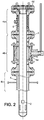
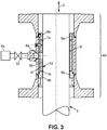
- an airlock according to the invention is shown. It has a guide 4 anchored in the domed roof 1b of a tank 1 of liquefied natural gas (or "LNG") 1a.
- the tank is partially represented.
- a shuttle 3 is in the engaged position in the tank. It borrows a passage 5a provided in the guide in a given direction 5, which is here vertical.
- the shuttle passes through a second roof 1c of the tank for thermally insulating the LNG 1a and its gaseous sky from the upper parts of the tank 1.
- a source 6b of industrial grade nitrogen that can flow to an inlet 6a in a chamber formed by the guide and the shuttle.
- the shuttle 3 has a generally tubular shape with a rounded end on the tank side.
- an instrument 2 which instrument is attached to the shuttle with fastening means such as hardware, welding or other.
- the instrument 2 may be for example an LNG presence detector, comprising a thermocouple or a controlled float.
- the instrument can also be a camera or any other element to collect information on the tank.
- the instrument can also be an element intended to have an active role in the tank.
- the shuttle is potentially mobile in the given direction 5. In this position of the shuttle, the tank is sealed at the flange 4d closing the guide 4 in the upper part, the side opposite the tank.
- the chamber 6 has an inlet 6a for connecting the chamber to a source of inert gas 6b through a pipe 6c.
- the inert gas may be nitrogen with a purity greater than or equal to 99% by volume, preferably greater than or equal to 99.99% by volume.
- it is possible in certain phases of use of the shuttle to maintain in the chamber a pressure greater than or equal to that of the reservoir. In general, it is a pressure between 105% and 150% of that of the tank, so as to prevent any leakage of the tank to the outside.
- An LNG tank typically has a relative internal pressure of about 100 to 300 hPa, an absolute pressure of about 1.1 to 1.3 atmospheres.
- two O-rings or lip seals 7a and 7b are arranged in the contact area closing the chamber between the inner surface of the guide and the outer surface of the shuttle.
- the shuttle has a round shape, without sharp edges (protruding or reentrant) in the direction of 5 sliding. Indeed, such edges reduce the seal and increase the consumption of inert gas to maintain the desired pressure in the chamber.
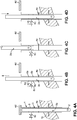
- FIGS. 4A to 4D illustrate different phases of a method according to the invention, implementing the airlock described above to remove an instrument, and then enter into an LNG tank.
- the tank is symbolized by its domed roof 1b.
- the guide 4 and the shuttle 3 of the airlock are represented in a stylized manner.
- the chamber 6 is connected by the pipe 6c to a source of inert gas, not shown.
- the shuttle is in a first position, the instrument being engaged in the tank.
- the flange 4d is in place, sealing the tank.
- the full-flow valve 4th is open, the shuttle passing through.
- the stop valve of the pipe 6c is closed. This is a normal use position of the instrument 2 in the tank.
- the detection of a visual cue 3b present on the external surface of the shuttle makes it possible to confirm that the shuttle is sufficiently raised in the guide.
- the valve 4e In this position to exit the instrument, the valve 4e being cleared, it can be closed. It then seals the tank as long as necessary to repair or change the instrument for example. We can then stop keeping the chamber 6 under pressure, since the relay was taken by the valve 4e.
Landscapes
- Engineering & Computer Science (AREA)
- Mechanical Engineering (AREA)
- General Engineering & Computer Science (AREA)
- Filling Or Discharging Of Gas Storage Vessels (AREA)
- Toys (AREA)
Claims (13)
- Verfahren zum Einführen/Herausnehmen eines Instruments (2) in einem Behälter (1), der dazu bestimmt ist, ein Fluid (1a) mit einem höheren Druck als dem Luftdruck zu enthalten, das einen Greifer (3), um das Instrument aufzunehmen, und eine Führung (4) des Greifers in dem Behälter einsetzt, wobei der Greifer innerhalb der Führung in einer gegebenen Gleitrichtung (5) beweglich ist,
wobei das Verfahren dadurch gekennzeichnet ist, dass es die folgenden Schritte umfasst:- Vorsehen einer Zone (4a) des Zusammenwirkens der Führung (4) mit dem Greifer (3), umfassend eine röhrenförmige Ausnehmung (6), die den Greifer (3) umgibt, wobei die Ausnehmung (6) begrenzt ist:* seitlich durch eine Innenfläche (5b) der Führung und eine Außenfläche (3a) des Greifers, und* längs durch mindestens zwei Kontaktzonen, eine obere und eine untere, zwischen der Außenfläche (3a) des Greifers und jeweiligen Verlängerungen (8a, 8b) der Innenfläche (5b) der Führung,und- bei einer Verschiebung des Greifers in der Führung in der gegebenen Gleitrichtung (5) in der Ausnehmung (6) Aufrechterhalten eines Drucks größer oder gleich dem Druck des in dem Behälter enthaltenen Fluids, wobei die Aufrechterhaltung des Drucks durch Einspritzen eines Inertgases in die Ausnehmung (6) erfolgt. - Verfahren nach Anspruch 1, bei dem das Inertgas Stickstoff mit einer Konzentration größer oder gleich 99 Vol.-% umfasst.
- Verfahren nach einem der Ansprüche 1 und 2, bei dem der in der Ausnehmung (6) aufrechterhaltene Druck zwischen 105 % und 150 % des Drucks des in dem Behälter enthaltenen Fluids beträgt.
- Verfahren nach Anspruch 1, bei dem die Führung mindestens zwei Dichtungen (7a, 7b) umfasst, die sich im Bereich der jeweiligen Verlängerungen (8a, 8b) befinden.
- Schleuse zum Einführen/Herausnehmen eines Instruments (2) in einem Behälter (1), der dazu bestimmt ist, ein Fluid (1a) mit einem höheren Druck als dem Luftdruck zu enthalten, wobei das System umfasst:- eine Führung (4), die dazu bestimmt ist, durch eine Wand des Behälters (1b, 1c) hindurchzugehen;- einen in einem Durchgang (5a) innerhalb der Führung (4) in einer gegebenen Gleitrichtung (5) beweglichen Greifer (3), wobei der Greifer Mittel zur Befestigung des Instruments (2) umfasst,wobei die Schleuse dadurch gekennzeichnet ist, dass sie umfasst:- eine Zone (4a) des Zusammenwirkens der Führung (4) mit dem Greifer (3), umfassend eine röhrenförmige Ausnehmung (6), die den Greifer (3) umgibt, wobei die Ausnehmung (6) begrenzt ist:* seitlich durch eine Innenfläche (5b) der Führung und eine Außenfläche (3a) des Greifers, und* längs durch mindestens zwei Kontaktzonen, eine obere und eine untere, zwischen der Außenfläche (3a) des Greifers und jeweiligen Verlängerungen (8a, 8b) der Innenfläche (5b) der Führungund- einen in der Ausnehmung (6) vorgesehenen Eingang für Inertgas (6a).
- Schleuse nach Anspruch 5, bei der, wobei der Greifer zwischen einer ersten Position, die dazu bestimmt ist, das Instrument in den Behälter einzusetzen, und einer zweiten Position, die dazu bestimmt ist, das Instrument aus dem Behälter herauszunehmen, beweglich ist, die Führung (4) ferner umfasst:- ein erstes Element (4d) zum Öffnen/Schließen des Durchgangs (5a), das auf der gegenüberliegenden Seite zum Behälter (1) in Bezug zu der Zone (4a) der Führung, die mit dem Greifer (3) zusammenwirkt, um die Ausnehmung (6) zu bilden, angeordnet ist, wobei das erste Element (4d) den Durchgang schließt, wenn sich der Greifer in der ersten Position befindet, und den Durchgang öffnet, wenn der Greifer von der ersten Position in die zweite Position übergeht; und- ein zweites Element (4e) zum Öffnen/Schließen des Durchgangs (5a), das auf der Seite des Behälters (1) in Bezug zu der Zone (4a) der Führung, die mit dem Greifer (3) zusammenwirkt, um die Ausnehmung (6) zu bilden, angeordnet ist, wobei das zweite Element (4e) den Durchgang schließt, wenn sich der Greifer in der zweiten Position befindet, und den Durchgang öffnet, wenn der Greifer von der zweiten Position in die erste Position übergeht.
- Schleuse nach Anspruch 6, bei der das erste Element (4d) ein Flansch ist.
- Schleuse nach einem der Ansprüche 6 und 7, bei der das zweite Element (4e) ein Kugelhahn mit vollem Durchgang ist, wobei der Greifer in den Kugelhahn eingreift, wenn er von der zweiten Position in die erste Position übergeht, und wobei der Greifer in dem Kugelhahn in Eingriff bleibt, wenn er sich in der ersten Position befindet.
- Schleuse nach Anspruch 8, bei der die Außenfläche (3a) des Greifers eine Markierung (3b) umfasst, die derart vorgesehen ist, dass ausgehend von einem Beobachtungspunkt außerhalb des Behälters (1) die Markierung von der Führung verdeckt wird, wenn der Greifer in dem zweiten Element (4e) in Eingriff ist, und dass die Markierung sichtbar ist, wenn der Greifer von dem zweiten Element gelöst ist.
- Schleuse nach einem der Ansprüche 5 bis 9, bei der die Führung mindestens zwei Dichtungen (7a, 7b) umfasst, die sich auf Höhe der jeweiligen Verlängerungen (8a, 8b) befinden.
- Schleuse nach einem der Ansprüche 5 bis 10, bei der die Außenfläche (3a) des Greifers zylindrisch und ohne freie Kante in die gegebene Gleitrichtung (5) ist.
- Schleuse nach Anspruch 11, bei der die Außenfläche (3a) des Greifers eine kreisförmige Basis hat.
- Behälter (1), der dazu bestimmt ist, Flüssigerdgas (1a) und Erdgaszusammensetzungen mit einem höheren Druck als dem Luftdruck zu enthalten, dadurch gekennzeichnet, dass er eine Schleuse nach einem der Ansprüche 5 bis 12 umfasst, wobei die Ausnehmung (6) über den Eingang (6a) mit einer Inertgasquelle (6b) in Fluidverbindung steht, die geeignet ist, in der Ausnehmung einen Druck größer oder gleich dem Druck der in dem Behälter enthaltenen Gaszusammensetzungen zu halten.
Applications Claiming Priority (1)
| Application Number | Priority Date | Filing Date | Title |
|---|---|---|---|
| FR1151314A FR2971831B1 (fr) | 2011-02-17 | 2011-02-17 | Procede pour realiser l'entree/sortie d'un instrument dans un reservoir. |
Publications (3)
| Publication Number | Publication Date |
|---|---|
| EP2489922A2 EP2489922A2 (de) | 2012-08-22 |
| EP2489922A3 EP2489922A3 (de) | 2017-07-12 |
| EP2489922B1 true EP2489922B1 (de) | 2018-05-16 |
Family
ID=44370580
Family Applications (1)
| Application Number | Title | Priority Date | Filing Date |
|---|---|---|---|
| EP12154584.2A Active EP2489922B1 (de) | 2011-02-17 | 2012-02-08 | Verfahren zum Einführen/Herausnehmen eines Instruments in einem Behälter |
Country Status (4)
| Country | Link |
|---|---|
| EP (1) | EP2489922B1 (de) |
| JP (1) | JP5328946B2 (de) |
| KR (1) | KR101315977B1 (de) |
| FR (1) | FR2971831B1 (de) |
Families Citing this family (1)
| Publication number | Priority date | Publication date | Assignee | Title |
|---|---|---|---|---|
| JPH0715049B2 (ja) | 1986-12-01 | 1995-02-22 | 大日本インキ化学工業株式会社 | 熱可塑性樹脂組成物 |
Family Cites Families (5)
| Publication number | Priority date | Publication date | Assignee | Title |
|---|---|---|---|---|
| FR1366755A (fr) * | 1962-12-28 | 1964-07-17 | Gaz De France | Procédé et dispositif pour le prélèvement d'échantillons de gaz liquéfiés à très basse température |
| FR2290628A1 (fr) * | 1974-11-05 | 1976-06-04 | Elf Monagaz | Procede et dispositif de demontage et de remontage d'un accessoire necessaire a l'etancheite d'un reservoir de fluide sous pression |
| JPS54149918A (en) * | 1978-05-16 | 1979-11-24 | Kawasaki Heavy Ind Ltd | Construction of level gauge fitting section of tanks |
| FR2543261B1 (fr) * | 1983-03-25 | 1985-08-16 | Gaz De France | Dispositif d'observation a l'interieur d'un reservoir cryogenique en service |
| JPS62297600A (ja) * | 1986-06-16 | 1987-12-24 | Tokyo Gas Co Ltd | タンク内部の観察装置 |
-
2011
- 2011-02-17 FR FR1151314A patent/FR2971831B1/fr active Active
-
2012
- 2012-02-08 EP EP12154584.2A patent/EP2489922B1/de active Active
- 2012-02-16 JP JP2012031418A patent/JP5328946B2/ja active Active
- 2012-02-17 KR KR1020120016138A patent/KR101315977B1/ko active Active
Non-Patent Citations (1)
| Title |
|---|
| None * |
Also Published As
| Publication number | Publication date |
|---|---|
| KR20120094866A (ko) | 2012-08-27 |
| EP2489922A3 (de) | 2017-07-12 |
| EP2489922A2 (de) | 2012-08-22 |
| JP2012172846A (ja) | 2012-09-10 |
| FR2971831B1 (fr) | 2013-03-29 |
| JP5328946B2 (ja) | 2013-10-30 |
| FR2971831A1 (fr) | 2012-08-24 |
| KR101315977B1 (ko) | 2013-10-08 |
Similar Documents
| Publication | Publication Date | Title |
|---|---|---|
| EP3129700B1 (de) | Versiegeltes wärmegedämmtes gefäss in einer schwimmenden struktur | |
| EP3074744B1 (de) | Überwachung einer versiegelten und wärmeisolierten wanne | |
| EP0251917B1 (de) | Lagerdichtheitsüberwachungsverfahren und Speicher, der dafür benutzt wird | |
| FR3017924A1 (fr) | Procede et systeme d'inertage d'une paroi d'une cuve de stockage d'un gaz combustible liquefie | |
| EP3867561B1 (de) | Vorrichtung zum befüllen und entnehmen von gas | |
| EP3956644B1 (de) | Vorrichtung zur überwachung der dichtigkeit von dichtungselementen | |
| EP1939606B1 (de) | Messverfahren der realen Porosität der Dichtungsbarriere eines Begrenzungsbehälters für Flüssigkeiten | |
| WO2020128370A1 (fr) | Procede de controle de l'etancheite d'une cuve etanche et thermiquement isolante de stockage d'un fluide | |
| EP2489922B1 (de) | Verfahren zum Einführen/Herausnehmen eines Instruments in einem Behälter | |
| KR20100055163A (ko) | 화물창의 기밀 검사방법 | |
| EP4136424B1 (de) | Vorrichtung zur überwachung der dichtigkeit von dichtungselementen | |
| EP0065922A1 (de) | Primärpumpe für einen Druckwasserreaktor, mit einem Dichtungssystem für ihre Antriebswelle | |
| WO2020229777A1 (fr) | Cuve de transport et/ou de stockage pour gaz sous forme liquide | |
| BE1031096B1 (fr) | Dispositif d’essai de performances d'étanchéité d'une vanne à hydrogène liquide | |
| WO2021144531A1 (fr) | Double trappe d'accès pour une cuve de transport de gaz liquéfié | |
| WO2023198853A1 (fr) | Installation pour le stockage et/ou le transport de gaz liquéfié | |
| EP1144321A1 (de) | Verfahren und vorrichtung zum ablassen eines geschmolzenen materials aus einem hafen | |
| EP2489995B1 (de) | Präsenzmelder einer Flüssigkeit | |
| FR2936274A1 (fr) | Dispositif de collecte de fluide | |
| EP4229382B1 (de) | Verfahren zur dichtheitsprüfung eines versiegelten und wärmeisolierenden tanks zur lagerung eines fluids | |
| EP3867727B1 (de) | Druckregler mit eingebautem sicherheitsventil zur druckentlastung im fall von überdruck stromabwärts | |
| EP0120777B1 (de) | Beobachtungsapparat für das Innere eines kryogenen Behälters während des Betriebes | |
| EP1634002B1 (de) | Füll- und leerventil und reinigungsgerät für einen flüssigkeitsdruckbehälter | |
| FR3067335A1 (fr) | Dispositif d'etancheite pour installation de separation de gaz | |
| EP0532435B1 (de) | Apparat und Verfahren zum Verschliessen von Kohlensäureflaschen |
Legal Events
| Date | Code | Title | Description |
|---|---|---|---|
| PUAI | Public reference made under article 153(3) epc to a published international application that has entered the european phase |
Free format text: ORIGINAL CODE: 0009012 |
|
| AK | Designated contracting states |
Kind code of ref document: A2 Designated state(s): AL AT BE BG CH CY CZ DE DK EE ES FI FR GB GR HR HU IE IS IT LI LT LU LV MC MK MT NL NO PL PT RO RS SE SI SK SM TR |
|
| AX | Request for extension of the european patent |
Extension state: BA ME |
|
| PUAL | Search report despatched |
Free format text: ORIGINAL CODE: 0009013 |
|
| AK | Designated contracting states |
Kind code of ref document: A3 Designated state(s): AL AT BE BG CH CY CZ DE DK EE ES FI FR GB GR HR HU IE IS IT LI LT LU LV MC MK MT NL NO PL PT RO RS SE SI SK SM TR |
|
| AX | Request for extension of the european patent |
Extension state: BA ME |
|
| RIC1 | Information provided on ipc code assigned before grant |
Ipc: F17C 13/02 20060101AFI20170607BHEP |
|
| STAA | Information on the status of an ep patent application or granted ep patent |
Free format text: STATUS: REQUEST FOR EXAMINATION WAS MADE |
|
| 17P | Request for examination filed |
Effective date: 20170721 |
|
| RBV | Designated contracting states (corrected) |
Designated state(s): AL AT BE BG CH CY CZ DE DK EE ES FI FR GB GR HR HU IE IS IT LI LT LU LV MC MK MT NL NO PL PT RO RS SE SI SK SM TR |
|
| GRAP | Despatch of communication of intention to grant a patent |
Free format text: ORIGINAL CODE: EPIDOSNIGR1 |
|
| STAA | Information on the status of an ep patent application or granted ep patent |
Free format text: STATUS: GRANT OF PATENT IS INTENDED |
|
| INTG | Intention to grant announced |
Effective date: 20171220 |
|
| GRAS | Grant fee paid |
Free format text: ORIGINAL CODE: EPIDOSNIGR3 |
|
| GRAA | (expected) grant |
Free format text: ORIGINAL CODE: 0009210 |
|
| STAA | Information on the status of an ep patent application or granted ep patent |
Free format text: STATUS: THE PATENT HAS BEEN GRANTED |
|
| AK | Designated contracting states |
Kind code of ref document: B1 Designated state(s): AL AT BE BG CH CY CZ DE DK EE ES FI FR GB GR HR HU IE IS IT LI LT LU LV MC MK MT NL NO PL PT RO RS SE SI SK SM TR |
|
| REG | Reference to a national code |
Ref country code: GB Ref legal event code: FG4D Free format text: NOT ENGLISH |
|
| REG | Reference to a national code |
Ref country code: CH Ref legal event code: EP |
|
| REG | Reference to a national code |
Ref country code: IE Ref legal event code: FG4D Free format text: LANGUAGE OF EP DOCUMENT: FRENCH |
|
| REG | Reference to a national code |
Ref country code: DE Ref legal event code: R096 Ref document number: 602012046311 Country of ref document: DE |
|
| REG | Reference to a national code |
Ref country code: AT Ref legal event code: REF Ref document number: 999915 Country of ref document: AT Kind code of ref document: T Effective date: 20180615 |
|
| REG | Reference to a national code |
Ref country code: NL Ref legal event code: MP Effective date: 20180516 |
|
| REG | Reference to a national code |
Ref country code: LT Ref legal event code: MG4D |
|
| PG25 | Lapsed in a contracting state [announced via postgrant information from national office to epo] |
Ref country code: BG Free format text: LAPSE BECAUSE OF FAILURE TO SUBMIT A TRANSLATION OF THE DESCRIPTION OR TO PAY THE FEE WITHIN THE PRESCRIBED TIME-LIMIT Effective date: 20180816 Ref country code: ES Free format text: LAPSE BECAUSE OF FAILURE TO SUBMIT A TRANSLATION OF THE DESCRIPTION OR TO PAY THE FEE WITHIN THE PRESCRIBED TIME-LIMIT Effective date: 20180516 Ref country code: LT Free format text: LAPSE BECAUSE OF FAILURE TO SUBMIT A TRANSLATION OF THE DESCRIPTION OR TO PAY THE FEE WITHIN THE PRESCRIBED TIME-LIMIT Effective date: 20180516 Ref country code: NO Free format text: LAPSE BECAUSE OF FAILURE TO SUBMIT A TRANSLATION OF THE DESCRIPTION OR TO PAY THE FEE WITHIN THE PRESCRIBED TIME-LIMIT Effective date: 20180816 Ref country code: FI Free format text: LAPSE BECAUSE OF FAILURE TO SUBMIT A TRANSLATION OF THE DESCRIPTION OR TO PAY THE FEE WITHIN THE PRESCRIBED TIME-LIMIT Effective date: 20180516 Ref country code: SE Free format text: LAPSE BECAUSE OF FAILURE TO SUBMIT A TRANSLATION OF THE DESCRIPTION OR TO PAY THE FEE WITHIN THE PRESCRIBED TIME-LIMIT Effective date: 20180516 |
|
| PG25 | Lapsed in a contracting state [announced via postgrant information from national office to epo] |
Ref country code: HR Free format text: LAPSE BECAUSE OF FAILURE TO SUBMIT A TRANSLATION OF THE DESCRIPTION OR TO PAY THE FEE WITHIN THE PRESCRIBED TIME-LIMIT Effective date: 20180516 Ref country code: RS Free format text: LAPSE BECAUSE OF FAILURE TO SUBMIT A TRANSLATION OF THE DESCRIPTION OR TO PAY THE FEE WITHIN THE PRESCRIBED TIME-LIMIT Effective date: 20180516 Ref country code: GR Free format text: LAPSE BECAUSE OF FAILURE TO SUBMIT A TRANSLATION OF THE DESCRIPTION OR TO PAY THE FEE WITHIN THE PRESCRIBED TIME-LIMIT Effective date: 20180817 Ref country code: LV Free format text: LAPSE BECAUSE OF FAILURE TO SUBMIT A TRANSLATION OF THE DESCRIPTION OR TO PAY THE FEE WITHIN THE PRESCRIBED TIME-LIMIT Effective date: 20180516 Ref country code: NL Free format text: LAPSE BECAUSE OF FAILURE TO SUBMIT A TRANSLATION OF THE DESCRIPTION OR TO PAY THE FEE WITHIN THE PRESCRIBED TIME-LIMIT Effective date: 20180516 |
|
| REG | Reference to a national code |
Ref country code: AT Ref legal event code: MK05 Ref document number: 999915 Country of ref document: AT Kind code of ref document: T Effective date: 20180516 |
|
| PG25 | Lapsed in a contracting state [announced via postgrant information from national office to epo] |
Ref country code: SK Free format text: LAPSE BECAUSE OF FAILURE TO SUBMIT A TRANSLATION OF THE DESCRIPTION OR TO PAY THE FEE WITHIN THE PRESCRIBED TIME-LIMIT Effective date: 20180516 Ref country code: RO Free format text: LAPSE BECAUSE OF FAILURE TO SUBMIT A TRANSLATION OF THE DESCRIPTION OR TO PAY THE FEE WITHIN THE PRESCRIBED TIME-LIMIT Effective date: 20180516 Ref country code: CZ Free format text: LAPSE BECAUSE OF FAILURE TO SUBMIT A TRANSLATION OF THE DESCRIPTION OR TO PAY THE FEE WITHIN THE PRESCRIBED TIME-LIMIT Effective date: 20180516 Ref country code: PL Free format text: LAPSE BECAUSE OF FAILURE TO SUBMIT A TRANSLATION OF THE DESCRIPTION OR TO PAY THE FEE WITHIN THE PRESCRIBED TIME-LIMIT Effective date: 20180516 Ref country code: DK Free format text: LAPSE BECAUSE OF FAILURE TO SUBMIT A TRANSLATION OF THE DESCRIPTION OR TO PAY THE FEE WITHIN THE PRESCRIBED TIME-LIMIT Effective date: 20180516 Ref country code: AT Free format text: LAPSE BECAUSE OF FAILURE TO SUBMIT A TRANSLATION OF THE DESCRIPTION OR TO PAY THE FEE WITHIN THE PRESCRIBED TIME-LIMIT Effective date: 20180516 Ref country code: EE Free format text: LAPSE BECAUSE OF FAILURE TO SUBMIT A TRANSLATION OF THE DESCRIPTION OR TO PAY THE FEE WITHIN THE PRESCRIBED TIME-LIMIT Effective date: 20180516 |
|
| REG | Reference to a national code |
Ref country code: DE Ref legal event code: R097 Ref document number: 602012046311 Country of ref document: DE |
|
| PG25 | Lapsed in a contracting state [announced via postgrant information from national office to epo] |
Ref country code: SM Free format text: LAPSE BECAUSE OF FAILURE TO SUBMIT A TRANSLATION OF THE DESCRIPTION OR TO PAY THE FEE WITHIN THE PRESCRIBED TIME-LIMIT Effective date: 20180516 Ref country code: IT Free format text: LAPSE BECAUSE OF FAILURE TO SUBMIT A TRANSLATION OF THE DESCRIPTION OR TO PAY THE FEE WITHIN THE PRESCRIBED TIME-LIMIT Effective date: 20180516 |
|
| PLBE | No opposition filed within time limit |
Free format text: ORIGINAL CODE: 0009261 |
|
| STAA | Information on the status of an ep patent application or granted ep patent |
Free format text: STATUS: NO OPPOSITION FILED WITHIN TIME LIMIT |
|
| 26N | No opposition filed |
Effective date: 20190219 |
|
| PG25 | Lapsed in a contracting state [announced via postgrant information from national office to epo] |
Ref country code: SI Free format text: LAPSE BECAUSE OF FAILURE TO SUBMIT A TRANSLATION OF THE DESCRIPTION OR TO PAY THE FEE WITHIN THE PRESCRIBED TIME-LIMIT Effective date: 20180516 |
|
| REG | Reference to a national code |
Ref country code: DE Ref legal event code: R119 Ref document number: 602012046311 Country of ref document: DE |
|
| REG | Reference to a national code |
Ref country code: CH Ref legal event code: PL |
|
| GBPC | Gb: european patent ceased through non-payment of renewal fee |
Effective date: 20190208 |
|
| PG25 | Lapsed in a contracting state [announced via postgrant information from national office to epo] |
Ref country code: LU Free format text: LAPSE BECAUSE OF NON-PAYMENT OF DUE FEES Effective date: 20190208 Ref country code: MC Free format text: LAPSE BECAUSE OF FAILURE TO SUBMIT A TRANSLATION OF THE DESCRIPTION OR TO PAY THE FEE WITHIN THE PRESCRIBED TIME-LIMIT Effective date: 20180516 |
|
| REG | Reference to a national code |
Ref country code: BE Ref legal event code: MM Effective date: 20190228 |
|
| REG | Reference to a national code |
Ref country code: IE Ref legal event code: MM4A |
|
| PG25 | Lapsed in a contracting state [announced via postgrant information from national office to epo] |
Ref country code: AL Free format text: LAPSE BECAUSE OF FAILURE TO SUBMIT A TRANSLATION OF THE DESCRIPTION OR TO PAY THE FEE WITHIN THE PRESCRIBED TIME-LIMIT Effective date: 20180516 |
|
| PG25 | Lapsed in a contracting state [announced via postgrant information from national office to epo] |
Ref country code: LI Free format text: LAPSE BECAUSE OF NON-PAYMENT OF DUE FEES Effective date: 20190228 Ref country code: CH Free format text: LAPSE BECAUSE OF NON-PAYMENT OF DUE FEES Effective date: 20190228 |
|
| PG25 | Lapsed in a contracting state [announced via postgrant information from national office to epo] |
Ref country code: IE Free format text: LAPSE BECAUSE OF NON-PAYMENT OF DUE FEES Effective date: 20190208 Ref country code: GB Free format text: LAPSE BECAUSE OF NON-PAYMENT OF DUE FEES Effective date: 20190208 Ref country code: DE Free format text: LAPSE BECAUSE OF NON-PAYMENT OF DUE FEES Effective date: 20190903 |
|
| PG25 | Lapsed in a contracting state [announced via postgrant information from national office to epo] |
Ref country code: BE Free format text: LAPSE BECAUSE OF NON-PAYMENT OF DUE FEES Effective date: 20190228 |
|
| PG25 | Lapsed in a contracting state [announced via postgrant information from national office to epo] |
Ref country code: TR Free format text: LAPSE BECAUSE OF FAILURE TO SUBMIT A TRANSLATION OF THE DESCRIPTION OR TO PAY THE FEE WITHIN THE PRESCRIBED TIME-LIMIT Effective date: 20180516 |
|
| PG25 | Lapsed in a contracting state [announced via postgrant information from national office to epo] |
Ref country code: MT Free format text: LAPSE BECAUSE OF FAILURE TO SUBMIT A TRANSLATION OF THE DESCRIPTION OR TO PAY THE FEE WITHIN THE PRESCRIBED TIME-LIMIT Effective date: 20180516 Ref country code: PT Free format text: LAPSE BECAUSE OF FAILURE TO SUBMIT A TRANSLATION OF THE DESCRIPTION OR TO PAY THE FEE WITHIN THE PRESCRIBED TIME-LIMIT Effective date: 20180917 |
|
| PG25 | Lapsed in a contracting state [announced via postgrant information from national office to epo] |
Ref country code: CY Free format text: LAPSE BECAUSE OF FAILURE TO SUBMIT A TRANSLATION OF THE DESCRIPTION OR TO PAY THE FEE WITHIN THE PRESCRIBED TIME-LIMIT Effective date: 20180516 |
|
| PG25 | Lapsed in a contracting state [announced via postgrant information from national office to epo] |
Ref country code: IS Free format text: LAPSE BECAUSE OF FAILURE TO SUBMIT A TRANSLATION OF THE DESCRIPTION OR TO PAY THE FEE WITHIN THE PRESCRIBED TIME-LIMIT Effective date: 20180916 |
|
| PG25 | Lapsed in a contracting state [announced via postgrant information from national office to epo] |
Ref country code: HU Free format text: LAPSE BECAUSE OF FAILURE TO SUBMIT A TRANSLATION OF THE DESCRIPTION OR TO PAY THE FEE WITHIN THE PRESCRIBED TIME-LIMIT; INVALID AB INITIO Effective date: 20120208 |
|
| PG25 | Lapsed in a contracting state [announced via postgrant information from national office to epo] |
Ref country code: MK Free format text: LAPSE BECAUSE OF FAILURE TO SUBMIT A TRANSLATION OF THE DESCRIPTION OR TO PAY THE FEE WITHIN THE PRESCRIBED TIME-LIMIT Effective date: 20180516 |
|
| P01 | Opt-out of the competence of the unified patent court (upc) registered |
Effective date: 20231024 |
|
| PGFP | Annual fee paid to national office [announced via postgrant information from national office to epo] |
Ref country code: FR Payment date: 20250121 Year of fee payment: 14 |