EP2489838A2 - Cooled component for the turbine of a gas turbine engine - Google Patents
Cooled component for the turbine of a gas turbine engine Download PDFInfo
- Publication number
- EP2489838A2 EP2489838A2 EP12152611A EP12152611A EP2489838A2 EP 2489838 A2 EP2489838 A2 EP 2489838A2 EP 12152611 A EP12152611 A EP 12152611A EP 12152611 A EP12152611 A EP 12152611A EP 2489838 A2 EP2489838 A2 EP 2489838A2
- Authority
- EP
- European Patent Office
- Prior art keywords
- flow
- passage
- linking
- entrance
- cooling fluid
- Prior art date
- Legal status (The legal status is an assumption and is not a legal conclusion. Google has not performed a legal analysis and makes no representation as to the accuracy of the status listed.)
- Granted
Links
Images


Classifications
-
- F—MECHANICAL ENGINEERING; LIGHTING; HEATING; WEAPONS; BLASTING
- F01—MACHINES OR ENGINES IN GENERAL; ENGINE PLANTS IN GENERAL; STEAM ENGINES
- F01D—NON-POSITIVE DISPLACEMENT MACHINES OR ENGINES, e.g. STEAM TURBINES
- F01D5/00—Blades; Blade-carrying members; Heating, heat-insulating, cooling or antivibration means on the blades or the members
- F01D5/12—Blades
- F01D5/14—Form or construction
- F01D5/18—Hollow blades, i.e. blades with cooling or heating channels or cavities; Heating, heat-insulating or cooling means on blades
- F01D5/186—Film cooling
-
- F—MECHANICAL ENGINEERING; LIGHTING; HEATING; WEAPONS; BLASTING
- F01—MACHINES OR ENGINES IN GENERAL; ENGINE PLANTS IN GENERAL; STEAM ENGINES
- F01D—NON-POSITIVE DISPLACEMENT MACHINES OR ENGINES, e.g. STEAM TURBINES
- F01D5/00—Blades; Blade-carrying members; Heating, heat-insulating, cooling or antivibration means on the blades or the members
- F01D5/12—Blades
- F01D5/14—Form or construction
- F01D5/18—Hollow blades, i.e. blades with cooling or heating channels or cavities; Heating, heat-insulating or cooling means on blades
- F01D5/187—Convection cooling
- F01D5/188—Convection cooling with an insert in the blade cavity to guide the cooling fluid, e.g. forming a separation wall
-
- F—MECHANICAL ENGINEERING; LIGHTING; HEATING; WEAPONS; BLASTING
- F01—MACHINES OR ENGINES IN GENERAL; ENGINE PLANTS IN GENERAL; STEAM ENGINES
- F01D—NON-POSITIVE DISPLACEMENT MACHINES OR ENGINES, e.g. STEAM TURBINES
- F01D5/00—Blades; Blade-carrying members; Heating, heat-insulating, cooling or antivibration means on the blades or the members
- F01D5/12—Blades
- F01D5/14—Form or construction
- F01D5/20—Specially-shaped blade tips to seal space between tips and stator
-
- F—MECHANICAL ENGINEERING; LIGHTING; HEATING; WEAPONS; BLASTING
- F01—MACHINES OR ENGINES IN GENERAL; ENGINE PLANTS IN GENERAL; STEAM ENGINES
- F01D—NON-POSITIVE DISPLACEMENT MACHINES OR ENGINES, e.g. STEAM TURBINES
- F01D9/00—Stators
- F01D9/06—Fluid supply conduits to nozzles or the like
-
- F—MECHANICAL ENGINEERING; LIGHTING; HEATING; WEAPONS; BLASTING
- F01—MACHINES OR ENGINES IN GENERAL; ENGINE PLANTS IN GENERAL; STEAM ENGINES
- F01D—NON-POSITIVE DISPLACEMENT MACHINES OR ENGINES, e.g. STEAM TURBINES
- F01D9/00—Stators
- F01D9/06—Fluid supply conduits to nozzles or the like
- F01D9/065—Fluid supply or removal conduits traversing the working fluid flow, e.g. for lubrication-, cooling-, or sealing fluids
-
- F—MECHANICAL ENGINEERING; LIGHTING; HEATING; WEAPONS; BLASTING
- F05—INDEXING SCHEMES RELATING TO ENGINES OR PUMPS IN VARIOUS SUBCLASSES OF CLASSES F01-F04
- F05D—INDEXING SCHEME FOR ASPECTS RELATING TO NON-POSITIVE-DISPLACEMENT MACHINES OR ENGINES, GAS-TURBINES OR JET-PROPULSION PLANTS
- F05D2240/00—Components
- F05D2240/10—Stators
- F05D2240/12—Fluid guiding means, e.g. vanes
- F05D2240/127—Vortex generators, turbulators, or the like, for mixing
-
- F—MECHANICAL ENGINEERING; LIGHTING; HEATING; WEAPONS; BLASTING
- F05—INDEXING SCHEMES RELATING TO ENGINES OR PUMPS IN VARIOUS SUBCLASSES OF CLASSES F01-F04
- F05D—INDEXING SCHEME FOR ASPECTS RELATING TO NON-POSITIVE-DISPLACEMENT MACHINES OR ENGINES, GAS-TURBINES OR JET-PROPULSION PLANTS
- F05D2240/00—Components
- F05D2240/80—Platforms for stationary or moving blades
- F05D2240/81—Cooled platforms
-
- F—MECHANICAL ENGINEERING; LIGHTING; HEATING; WEAPONS; BLASTING
- F05—INDEXING SCHEMES RELATING TO ENGINES OR PUMPS IN VARIOUS SUBCLASSES OF CLASSES F01-F04
- F05D—INDEXING SCHEME FOR ASPECTS RELATING TO NON-POSITIVE-DISPLACEMENT MACHINES OR ENGINES, GAS-TURBINES OR JET-PROPULSION PLANTS
- F05D2260/00—Function
- F05D2260/20—Heat transfer, e.g. cooling
- F05D2260/221—Improvement of heat transfer
- F05D2260/2212—Improvement of heat transfer by creating turbulence
-
- F—MECHANICAL ENGINEERING; LIGHTING; HEATING; WEAPONS; BLASTING
- F05—INDEXING SCHEMES RELATING TO ENGINES OR PUMPS IN VARIOUS SUBCLASSES OF CLASSES F01-F04
- F05D—INDEXING SCHEME FOR ASPECTS RELATING TO NON-POSITIVE-DISPLACEMENT MACHINES OR ENGINES, GAS-TURBINES OR JET-PROPULSION PLANTS
- F05D2260/00—Function
- F05D2260/20—Heat transfer, e.g. cooling
- F05D2260/221—Improvement of heat transfer
- F05D2260/2214—Improvement of heat transfer by increasing the heat transfer surface
- F05D2260/22141—Improvement of heat transfer by increasing the heat transfer surface using fins or ribs
Definitions
- the present invention relates to a cooled component, such as an aerofoil blade or vane, for use in gas turbine engines.
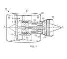
- a ducted fan gas turbine engine generally indicated at 10 has a principal and rotational axis X-X.
- the engine comprises, in axial flow series, an air intake 11, a propulsive fan 12, an intermediate pressure compressor 13, a high-pressure compressor 14, combustion equipment 15, a high-pressure turbine 16, and intermediate-pressure turbine 17, a low-pressure turbine 18 and a core engine exhaust nozzle 19.
- a nacelle 21 generally surrounds the engine 10 and defines the intake 11, a bypass duct 22 and a bypass exhaust nozzle 23.
- the gas turbine engine 10 works in a conventional manner so that air entering the intake 11 is accelerated by the fan 12 to produce two air flows: a first air flow A into the intermediate pressure compressor 14 and a second air flow B which passes through the bypass duct 22 to provide propulsive thrust.
- the intermediate pressure compressor 13 compresses the air flow A directed into it before delivering that air to the high pressure compressor 14 where further compression takes place.
- the compressed air exhausted from the high-pressure compressor 14 is directed into the combustion equipment 15 where it is mixed with fuel and the mixture combusted.
- the resultant hot combustion products then expand through, and thereby drive the high, intermediate and low-pressure turbines 16, 17, 18 before being exhausted through the nozzle 19 to provide additional propulsive thrust.
- the high, intermediate and low-pressure turbines respectively drive the high and intermediate pressure compressors 14, 13 and the fan 12 by suitable interconnecting shafts.
- the high-pressure turbine gas temperatures are hotter than the melting point of the material of the blades and vanes, necessitating internal air cooling of these airfoil components.
- the mean temperature of the gas stream decreases as power is extracted. Therefore, the need to cool the static and rotary parts of the engine structure decreases as the gas moves from the high-pressure stage(s), through the intermediate-pressure and low-pressure stages, and towards the exit nozzle.
- Figure 2 shows an isometric view of a typical single stage cooled turbine. Cooling air flows are indicated by arrows.
- High-pressure turbine nozzle guide vanes 31 consume the greatest amount of cooling air on high temperature engines.
- High-pressure blades 32 typically use about half of the NGV flow.
- the intermediate-pressure and low-pressure stages downstream of the HP turbine use progressively less cooling air.
- the high-pressure turbine airfoils are cooled by using high pressure air from the compressor that has by-passed the combustor and is therefore relatively cool compared to the gas temperature.
- Typical cooling air temperatures are between 800 and 1000 K, while gas temperatures can be in excess of 2100 K.
- the cooling air from the compressor that is used to cool the hot turbine components is not used fully to extract work from the turbine. Therefore, as extracting coolant flow has an adverse effect on the engine operating efficiency, it is important to use the cooling air effectively.
- a turbine blade or vane has a longitudinally extending aerofoil portion with facing suction side and pressure side walls. These aerofoil portions extend across the working gas annulus, with the longitudinal direction of the aerofoil portion being along a radial direction of the engine.
- Figure 3 shows a longitudinal cross-section through a high-pressure turbine blade.
- a multi-pass cooling passage 33 is fed cooling air by a feed passage 34 at the root of the blade. Cooling air eventually leaves the multi-pass cooling passage through exit holes at the tip 35 and the trailing edge 36 of the blade. Some of the cooling air, however, can leave the multi-pass cooling passage through effusion holes (not shown) formed in the suction side and pressure side walls.
- the block arrows in Figure 3 show the general direction of cooling air flow.
- the (triple) multi-pass cooling passage 33 is formed by two divider walls 37 which interconnect the facing suction side and pressure side walls of the aerofoil portion to form three longitudinally extending, side-by-side passage portions 38.
- Other aerofoil portions can have more or fewer divider walls and passage portions.
- the passage portions are connected in series fluid flow relationship by respective bends 39 which are formed by the joined ends of neighbouring passage portions.
- the cooling air thus enters the multi-pass cooling passage at the passage portion at the leading edge of the aerofoil portion and flows through each passage portion in turn to eventually leave from the passage portion at the trailing edge.
- Trip strip 40 and pedestal 41 heat transfer augmentation devices in the passage portions enhance heat transfer between the cooling air and the metal.
- the labels P1 to P8 denote the local pressures at the feed passage 34 (P1), the trailing edge 36 (P8) and locations in the passage portions 38 (P2-P7).
- the pressure in general falls significantly from P1 to P8 due to bend losses and frictional losses associated with the heat transfer augmentation devices 40, 41. However, these pressure drops are modified by the centrifugal pumping effect experienced by the cooling air in rotor blades. Thus there is a pressure gain in outward flowing passages and an additional pressure loss in inward flowing passages.
- the complicated internal structure of the aerofoil portion is generally formed by an investment casting procedure.
- the mould for the aerofoil portion has a core structure which is a "negative" of the ultimate internal structure of the aerofoil portion.
- the mould has passage features corresponding to the longitudinally extending passage portions 38. These passage features are relatively fragile, and to provide strengthening and preserve wall thicknesses it is usually necessary to provide "core ties" which extend between the passage features.
- the core ties are positioned in the vicinity of the bends 39 and midway along the passage portions.
- the core ties result in linking passages 42 which extend across the divider walls, each linking passage having an entrance in one passage portion and an exit in a neighbouring passage portion. The linking passages thus allow cooling air to leak across the divider walls, and the leaked cooling air short circuits the cooling scheme of the multi-pass cooling passage 33.
- the leakage flow that exits from the linking passages 42 disrupts the flow of air in the passage portions 38, causing it to slow down locally, changing the pressure losses, and reducing the local Reynolds number and internal heat transfer coefficient. Local dead spots can be created in the cooling air flow e.g. downstream of linking passage entrances and upstream of linking passage exits.
- the linking passages can modify the flow distribution inside the cooling scheme and increase the amount of cooling air required to cool the aerofoil. This in turn increases aerodynamic losses, reduces engine efficiency and elevates engine specific fuel consumption. Therefore, it would be desirable to reduce the leakage flow through the core tie linking passages.
- the present invention is at least partly based on the recognition that the quantity of cooling air leaking across a core-tie linking passage is a function of the pressure ratio between the upstream and downstream sides of the linking passage, the upstream pressure, and the flow cross-sectional area of the linking passage.
- One option might, therefore, be to reduce the flow cross-sectional area.
- the physical size of core ties which is determined by the need to strengthen a core, typically cannot be easily reduced.
- the position and shape of the core ties cannot easily be changed.
- an object of the present invention is to provide a component in which the difference in the static pressure of the cooling fluid between the entrance of a core tie linking passage and the exit of that core tie linking passage is reduced.
- a first aspect of the present invention provides a component for the turbine of a gas turbine engine, the component including:
- the leakage flow through the passage can be decreased, leading to reductions in aerodynamic losses, increases in engine efficiency and reduced engine specific fuel consumption.
- the component may have any one or, to the extent that they are compatible, any combination of the following optional features.
- the or each differential pressure reducing arrangement can include a flow accelerating formation in the upstream passage portion, the flow accelerating formation increasing the velocity of the cooling fluid flow in the upstream passage portion at the entrance of the core tie linking passage.
- the static pressure at the entrance of the core tie linking passage can be decreased to reduce the differential pressure across the linking passage.
- the flow accelerating formation may include one or more flow splitting members in the upstream passage portion, the or each flow splitting member interconnecting the facing walls and extending in the direction of flow of the cooling fluid to form, on a longitudinal cross-section through the aerofoil portion, an elongate island around which the cooling fluid flow splits in the upstream passage portion.
- the one or more flow splitting members can produce a flow pathway around the member or members distal the entrance of the linking passage, and a flow pathway around the member or members proximal the entrance of the linking passage, the distal flow path having an entry flow cross-sectional area A1 and an exit flow cross-sectional area A3, and the proximal flow path having an entry flow cross-sectional area A2 and an exit flow cross-sectional area A4.
- A4/A3 ⁇ A2/A1
- the flow accelerating formation includes a local reduction in the flow cross-sectional area of the upstream passage portion at the entrance of the core tie linking passage.
- a local thickening in the divider wall facing the entrance of the core tie linking passage can produce the local reduction in the flow cross-sectional area.
- the or each differential pressure reducing arrangement includes a flow decelerating formation in the downstream passage portion, the flow decelerating formation decreasing the velocity of the cooling fluid flow in the downstream passage portion at the exit of the core tie linking passage.
- the flow decelerating formation can include one or more flow splitting members in the downstream passage portion, the or each flow splitting member interconnecting the facing walls and extending in the direction of flow of the cooling fluid to form, on a longitudinal cross-section through the aerofoil portion, an elongate island around which the cooling fluid flow splits in the downstream passage portion.
- a flow splitting member(s) which serves to increase the velocity of the cooling fluid flow at the entrance of one core tie linking passage can also serve to decrease the velocity of the cooling fluid flow at the exit from another core tie linking passage.
- Such a configuration may be adopted when the first linking passage's exit is at the entry to a bend formed by the joined ends of neighbouring passage portions and the second linking passage's entrance is at the exit from the bend.
- the flow splitting member(s) may then extend around the bend.
- the flow decelerating formation may include a flow blocking structure in the downstream passage portion at the downstream side of the exit of the core tie linking passage, the flow blocking structure converting the dynamic component of the cooling fluid flow in the downstream passage portion at the exit of the core tie linking passage into an increased static pressure.
- the or each differential pressure reducing arrangement may include a flow deflector structure in the upstream passage portion, the flow deflector structure substantially locally removing the dynamic component of the cooling fluid flow in the upstream passage portion at the entrance of the core tie linking passage.
- the flow deflector structure can form a protected cavity in front of the entrance of the linking passage.
- a flow blocking structure in the downstream passage portion at the downstream side of the exit of the linking passage such a configuration can help to reduce the differential pressure across the linking passage.
- the component may be an aerofoil blade or vane, the two walls being the suction side and the pressure side walls of the aerofoil portion of the blade or vane.
- the aerofoil portion extends longitudinally in a radial direction of the engine, the divider walls and the cooling fluid passage portions being generally aligned along the longitudinal direction of the aerofoil portion.
- the component may provide an endwall to the working gas annulus of the engine, one of the two facing walls being the endwall.
- a component may be a shroud segment or a vane platform.
- a second aspect of the present invention provides gas turbine engine having one or more components according to the previous aspect.
- the present invention aims at reducing the cooling flow leakage across core-tie leakage passages by reducing the feed pressure and pressure ratio across these features.
- the local pressure differential that drives the flow across the core-tie leakage passages can be reduced by increasing the velocity of the flow in the passage portion at the entrance of (i.e. on the upstream side of) the leakage passage and/or decreasing the velocity of the flow in the passage portion at the exit of (i.e. on the downstream side of) the leakage passage.
- the static pressure differential is the driver of the leakage flow.
- the total pressure in the passage portions is comprised of two components, the static pressure and the dynamic pressure. If the dynamic pressure increases at a leakage passage entrance then the static pressure falls to compensate. Conversely, if the dynamic pressure decreases at a leakage passage exit then the static pressure increases.
- a flow accelerating formation can be introduced into the passage portion.
- the formation can be in the form of a reduced cross-sectional flow area of an entire passage portion.
- this increases the velocity across the entire passage portion, and thus changes the pressure drop for the whole multi-pass cooling passage, which can reduce overall cooling air flow rates. Therefore, a preferred option is to incorporate one or more flow splitting members into the passage portion to increase the flow velocity locally at the leakage passage entrance.
- a flow decelerating formation can be introduced into a passage portion at a leakage passage exit that decreases the flow velocity locally at the exit.
- FIGS 4 to 9 show embodiments of the present invention. Corresponding or similar features in Figures 4 to 9 have the same reference numbers.
- FIG 4 shows the lower part of a longitudinal cross-section through a high-pressure turbine blade according to a first embodiment of the present invention.
- An inlet feed passage 134 at the root of the blade directs cooling air to a multi-pass cooling passage 133 formed by three longitudinally extending, side-by-side passage portions 138a-c.
- Two divider walls 137 interconnect the facing suction side and pressure side walls of the aerofoil portion of the blade to partially define the passage portions.
- 180° bends 139 (only the lower one shown in Figure 3 ) formed by the joined ends of neighbouring passage portions connect the passage portions in series fluid flow relationship.
- the cooling air from inlet feed passage travels first upwards along the passage portion 138a at the leading edge of the aerofoil portion, then down the middle passage portion 138b, and finally upwards again along passage portion 138c at the trailing edge.
- a core-tie linking passage 142 extends across the bottom of the divider wall 137 between the leading edge 138a and middle 138b passage portions, causing some cooling air to bypass the upper bend (not shown) joining these passage portions.
- a flow splitting member 143a is located in the inlet feed passage 134 and extends into the leading edge passage portion adjacent to the linking passage entrance. The flow splitting member interconnects the suction side and pressure side walls and extends in the direction of flow of the cooling air. It thus forms, on the longitudinal cross-section of Figure 4 , an elongate island around which the cooling air flow divides to provide two flow pathways.
- the flow pathway furthest from the entrance of the linking passage has a mouth flow cross-sectional area denoted A1 in Figure 4 and an exit cross-sectional area denoted A3.
- the flow pathway closest to the entrance of the linking passage has a mouth flow cross-sectional area denoted A2 and an exit cross-sectional area (in front of the entrance of the linking passage) denoted A4.
- the relative proportions of the coolant flow passing through the two pathways is a function of the flow areas A1, A2, A3 and A4.
- the local velocity in the leading edge passage portion 138a that supplies linking passage 142 can be increased by the positioning of the flow splitting member 143a in the feed passage 134 and in the leading edge passage portion.
- the local static pressure Ps2 at the entrance to the linking passage falls, reducing the pressure level and pressure ratio (Ps2/P5) across the linking passage, and therefore reducing the leakage flow through the linking passage.
- the shape of the flow splitting member 143a can be as shown in Figure 4 or can be another smooth shape that accelerates the flow without causing separation.
- Figure 5 shows the upper part of a longitudinal cross-section through a high-pressure turbine blade according to a second embodiment of the present invention.
- a core-tie linking passage 142 extends across the top of the divider wall 137 between the middle 138b and trailing edge 138c passage portions, causing some cooling air to bypass the lower bend (not shown) joining these passage portions.
- a flow accelerating formation is provided by a local thickening 144 in the side of the divider wall 137 facing the entrance to the linking passage 142, i.e. the divider wall has an increased radius at its tip forming the inside of the 180° upper bend 139 causing the flow cross-sectional area A1 at the entry of the bend to be greater than the flow area A2 at the exit of the bend.
- the coolant flow travels up the leading edge passage portion 138a in a radially outward direction, enters the 180° bend and is accelerated in the second half of the bend past the entrance to the linking passage.
- the local velocity around the bend increases, causing the local static pressure Ps4 at the entrance to the linking passage to fall, reducing the pressure level and pressure ratio (Ps4 /P7) across the linking passage, and therefore reducing the leakage flow.
- the shape of the acceleration feature can be optimised to eliminate any localised flow reversal that may take place close to the inside of the bend.
- Figure 6 shows the upper part of a longitudinal cross-section through a high-pressure turbine blade according to a third embodiment of the present invention.
- a core-tie linking passage 142 extends across the top of the divider wall 137 between the middle 138b and trailing edge 138c passage portions, causing some cooling air to bypass the lower bend (not shown) joining these passage portions.
- a flow acceleration formation is provided by flow splitting member 143b in the 180° upper bend 139.
- the coolant flow travels up the leading edge passage portion 138a in a radially outward direction, enters the 180° bend, and divides between two pathways either side of the flow splitting member.
- the flow is locally accelerated past the entrance to the linking passage 142.
- the local static pressure Ps4 at the entrance falls, reducing the pressure level and pressure ratio (Ps4 /P7) across the linking passage, and therefore reducing the leakage flow.
- the flow splitting member can be segmented into overlapping smaller flow splitting members 143c, as shown in Figure 7 , which shows the upper part of a longitudinal cross-section through a high-pressure turbine blade according to a variant of the third embodiment of the present invention.
- Figure 8 shows the upper part of a longitudinal cross-section through a high-pressure turbine blade according to a fourth embodiment of the present invention.
- the multi-pass cooling passage 133 is formed by five longitudinally extending, side-by-side passage portions 138a-e.
- a core-tie linking passage 142a extends across the top of the divider wall 137 between the second 138b and third 138c passage portions, causing some cooling air to bypass a first lower bend (not shown) joining these passage portions.
- Another core-tie linking passage 142b extends across the top of the divider wall between the fourth 138d and trailing edge 138e passage portions, causing some cooling air to bypass a second lower bend (not shown) joining these passage portions.
- Flow acceleration formations are provided by a first flow splitting member 143d in the first 180° upper bend 139a (joining the leading edge 138a and second 138b passage portions), and a second flow splitting member 143e in the second 180° upper bend 139b (joining the third 138c and fourth 138d passage portions).
- the flow splitting member are configured in a similar way to the flow splitting member 143b of the third embodiment of Figure 6 in order to reduce the local static pressure at the entrances of the linking passages 142, and therefore reduce the leakage flows.
- the second flow splitting member 143e has the added benefit of increasing the local static pressure by virtue of decreasing the local velocity.
- this flow splitting member further reduces the leakage flow through the linking passage 142a as well as reducing the leakage flow through the linking passage 142b.
- Figure 9 shows the upper part of a longitudinal cross-section through a high-pressure turbine blade according to a fifth embodiment of the present invention.
- a core-tie linking passage 142 extends across the top of the divider wall 137 between the middle 138b and trailing edge 138c passage portions, causing some cooling air to bypass the lower bend (not shown) joining these passage portions.
- coolant flow travels up the leading edge passage portion 138a in a radially outward direction, enters 180° upper bend 139, and then travels down middle passage portion 138b.
- a flow deflector structure 145 extends from an outer wall 146 of the aerofoil portion across the entrance to the linking passage 142. The shape and location of the flow deflector structure creates a cavity 147 in front of the entrance.
- any coolant flow that enters the cavity 147 has to negotiate a tight 180° bend. This helps to ensure that most of the dynamic component of the total pressure is lost and the static pressure of the coolant becomes the feed pressure to the linking passage 142.
- a flow blocking structure such a pedestal or pin fin, can be incorporated into the entry to the cavity to further reduce the feed pressure.
- the local static pressure can be increased by providing a further flow blocking structure, such as a rib or trip strip, at the downstream side of the exit.
- the further flow blocking structure could take the form of structure extending from the outer wall 146 across the exit to the linking passage in the manner of a mirror image to the flow deflector structure 145. Such a structure would form a cavity in front of the exit that would trap the oncoming coolant flow, locally converting its dynamic pressure into an increased static pressure.
- the present invention provides a means of reducing the quantity of coolant air leaking across a core-tie linking passages by changing the local feed pressure, and pressure ratio, experienced by the linking passages.
- the local pressure is at the entrance to a core-tie linking passage can be increased by accelerating the flow using a geometric feature positioned in the upstream passage portion.
- the local pressure downstream of the linking passage can be increased by decelerating the flow using a geometric feature positioned in the downstream passage portion.
- the reduced leakage flow has a beneficial effect on cooling efficiency, which leads to an decreased cooling requirement and associated reduction in aerodynamic mixing losses.
Abstract
Description
- The present invention relates to a cooled component, such as an aerofoil blade or vane, for use in gas turbine engines.
- With reference to
Figure 1 , a ducted fan gas turbine engine generally indicated at 10 has a principal and rotational axis X-X. The engine comprises, in axial flow series, anair intake 11, apropulsive fan 12, anintermediate pressure compressor 13, a high-pressure compressor 14,combustion equipment 15, a high-pressure turbine 16, and intermediate-pressure turbine 17, a low-pressure turbine 18 and a coreengine exhaust nozzle 19. Anacelle 21 generally surrounds the engine 10 and defines theintake 11, abypass duct 22 and abypass exhaust nozzle 23. - The gas turbine engine 10 works in a conventional manner so that air entering the
intake 11 is accelerated by thefan 12 to produce two air flows: a first air flow A into theintermediate pressure compressor 14 and a second air flow B which passes through thebypass duct 22 to provide propulsive thrust. Theintermediate pressure compressor 13 compresses the air flow A directed into it before delivering that air to thehigh pressure compressor 14 where further compression takes place. - The compressed air exhausted from the high-
pressure compressor 14 is directed into thecombustion equipment 15 where it is mixed with fuel and the mixture combusted. The resultant hot combustion products then expand through, and thereby drive the high, intermediate and low-pressure turbines nozzle 19 to provide additional propulsive thrust. The high, intermediate and low-pressure turbines respectively drive the high andintermediate pressure compressors fan 12 by suitable interconnecting shafts. - The performance of gas turbine engines, whether measured in terms of efficiency or specific output, is improved by increasing the turbine gas temperature. It is therefore desirable to operate the turbines at the highest possible temperatures. For any engine cycle compression ratio or bypass ratio, increasing the turbine entry gas temperature produces more specific thrust (e.g. engine thrust per unit of air mass flow). However as turbine entry temperatures increase, the life of an un-cooled turbine falls, necessitating the development of better materials and the introduction of internal air cooling.
- In modern engines, the high-pressure turbine gas temperatures are hotter than the melting point of the material of the blades and vanes, necessitating internal air cooling of these airfoil components. During its passage through the engine, the mean temperature of the gas stream decreases as power is extracted. Therefore, the need to cool the static and rotary parts of the engine structure decreases as the gas moves from the high-pressure stage(s), through the intermediate-pressure and low-pressure stages, and towards the exit nozzle.
-
Figure 2 shows an isometric view of a typical single stage cooled turbine. Cooling air flows are indicated by arrows. - Internal convection and external films are the prime methods of cooling the gas path components - airfoils, platforms, shrouds and shroud segments etc. High-pressure turbine nozzle guide vanes 31 (NGVs) consume the greatest amount of cooling air on high temperature engines. High-
pressure blades 32 typically use about half of the NGV flow. The intermediate-pressure and low-pressure stages downstream of the HP turbine use progressively less cooling air. - The high-pressure turbine airfoils are cooled by using high pressure air from the compressor that has by-passed the combustor and is therefore relatively cool compared to the gas temperature. Typical cooling air temperatures are between 800 and 1000 K, while gas temperatures can be in excess of 2100 K.
- The cooling air from the compressor that is used to cool the hot turbine components is not used fully to extract work from the turbine. Therefore, as extracting coolant flow has an adverse effect on the engine operating efficiency, it is important to use the cooling air effectively.
- Ever increasing gas temperature levels combined with a drive towards flatter combustion radial profiles, in the interests of reduced combustor emissions, have resulted in an increase in local gas temperature experienced by the extremities of the blades and vanes, and the working gas annulus endwalls.
- A turbine blade or vane has a longitudinally extending aerofoil portion with facing suction side and pressure side walls. These aerofoil portions extend across the working gas annulus, with the longitudinal direction of the aerofoil portion being along a radial direction of the engine.
Figure 3 shows a longitudinal cross-section through a high-pressure turbine blade. Amulti-pass cooling passage 33 is fed cooling air by afeed passage 34 at the root of the blade. Cooling air eventually leaves the multi-pass cooling passage through exit holes at thetip 35 and thetrailing edge 36 of the blade. Some of the cooling air, however, can leave the multi-pass cooling passage through effusion holes (not shown) formed in the suction side and pressure side walls. The block arrows inFigure 3 show the general direction of cooling air flow. - The (triple)
multi-pass cooling passage 33 is formed by twodivider walls 37 which interconnect the facing suction side and pressure side walls of the aerofoil portion to form three longitudinally extending, side-by-side passage portions 38. Other aerofoil portions can have more or fewer divider walls and passage portions. The passage portions are connected in series fluid flow relationship byrespective bends 39 which are formed by the joined ends of neighbouring passage portions. The cooling air thus enters the multi-pass cooling passage at the passage portion at the leading edge of the aerofoil portion and flows through each passage portion in turn to eventually leave from the passage portion at the trailing edge.Trip strip 40 andpedestal 41 heat transfer augmentation devices in the passage portions enhance heat transfer between the cooling air and the metal. - In
Figure 3 , the labels P1 to P8 denote the local pressures at the feed passage 34 (P1), the trailing edge 36 (P8) and locations in the passage portions 38 (P2-P7). The pressure in general falls significantly from P1 to P8 due to bend losses and frictional losses associated with the heattransfer augmentation devices - The complicated internal structure of the aerofoil portion is generally formed by an investment casting procedure. Thus the mould for the aerofoil portion has a core structure which is a "negative" of the ultimate internal structure of the aerofoil portion. In particular, the mould has passage features corresponding to the longitudinally extending
passage portions 38. These passage features are relatively fragile, and to provide strengthening and preserve wall thicknesses it is usually necessary to provide "core ties" which extend between the passage features. Typically, the core ties are positioned in the vicinity of thebends 39 and midway along the passage portions. In the final aerofoil portion, the core ties result in linkingpassages 42 which extend across the divider walls, each linking passage having an entrance in one passage portion and an exit in a neighbouring passage portion. The linking passages thus allow cooling air to leak across the divider walls, and the leaked cooling air short circuits the cooling scheme of themulti-pass cooling passage 33. - More particularly, the leakage flow that exits from the linking
passages 42 disrupts the flow of air in thepassage portions 38, causing it to slow down locally, changing the pressure losses, and reducing the local Reynolds number and internal heat transfer coefficient. Local dead spots can be created in the cooling air flow e.g. downstream of linking passage entrances and upstream of linking passage exits. Thus the linking passages can modify the flow distribution inside the cooling scheme and increase the amount of cooling air required to cool the aerofoil. This in turn increases aerodynamic losses, reduces engine efficiency and elevates engine specific fuel consumption. Therefore, it would be desirable to reduce the leakage flow through the core tie linking passages. - The present invention is at least partly based on the recognition that the quantity of cooling air leaking across a core-tie linking passage is a function of the pressure ratio between the upstream and downstream sides of the linking passage, the upstream pressure, and the flow cross-sectional area of the linking passage. One option might, therefore, be to reduce the flow cross-sectional area. However, the physical size of core ties, which is determined by the need to strengthen a core, typically cannot be easily reduced. Also, due to stress field considerations, the position and shape of the core ties cannot easily be changed. Thus, an object of the present invention is to provide a component in which the difference in the static pressure of the cooling fluid between the entrance of a core tie linking passage and the exit of that core tie linking passage is reduced.
- Accordingly, a first aspect of the present invention provides a component for the turbine of a gas turbine engine, the component including:
- two facing walls interconnected by one or more generally elongate divider members to partially define side-by-side, generally elongate, cooling fluid passage portions which form a multi-pass cooling passage within the component, the passage portions being connected in series fluid flow relationship by respective bends formed by joined ends of neighbouring of the passage portions, and
- one or more core tie linking passages formed in the divider members, the or each core tie linking passage having an entrance at an upstream passage portion and an exit at a neighbouring downstream passage portion, and allowing cooling fluid to leak therethrough to bypass the bend formed by the joined ends of the neighbouring passage portions,
- wherein one or more differential pressure reducing arrangements are formed in the multi-pass cooling passage adjacent respective of the core tie linking passages, the or each arrangement reducing the difference in the static pressure of the cooling fluid between the entrance of the respective core tie linking passage and the exit of that core tie linking passage.
- By reducing the differential static pressure across the or each linking passage, the leakage flow through the passage can be decreased, leading to reductions in aerodynamic losses, increases in engine efficiency and reduced engine specific fuel consumption.
- The component may have any one or, to the extent that they are compatible, any combination of the following optional features.
- The or each differential pressure reducing arrangement can include a flow accelerating formation in the upstream passage portion, the flow accelerating formation increasing the velocity of the cooling fluid flow in the upstream passage portion at the entrance of the core tie linking passage. By increasing the velocity of the cooling fluid flow, the static pressure at the entrance of the core tie linking passage can be decreased to reduce the differential pressure across the linking passage.
- The flow accelerating formation may include one or more flow splitting members in the upstream passage portion, the or each flow splitting member interconnecting the facing walls and extending in the direction of flow of the cooling fluid to form, on a longitudinal cross-section through the aerofoil portion, an elongate island around which the cooling fluid flow splits in the upstream passage portion. By dividing the flow around the flow splitting member, the flow conditions can be controlled to increase the velocity of the cooling fluid flow at the entrance of the core tie linking passage. For example, the one or more flow splitting members can produce a flow pathway around the member or members distal the entrance of the linking passage, and a flow pathway around the member or members proximal the entrance of the linking passage, the distal flow path having an entry flow cross-sectional area A1 and an exit flow cross-sectional area A3, and the proximal flow path having an entry flow cross-sectional area A2 and an exit flow cross-sectional area A4. By setting A4/A3 < A2/A1, an increased velocity of the cooling fluid flow at the entrance of the core tie linking passage can be achieved.
- Optionally, the flow accelerating formation includes a local reduction in the flow cross-sectional area of the upstream passage portion at the entrance of the core tie linking passage. For example, a local thickening in the divider wall facing the entrance of the core tie linking passage can produce the local reduction in the flow cross-sectional area.
- Additionally or alternatively, the or each differential pressure reducing arrangement includes a flow decelerating formation in the downstream passage portion, the flow decelerating formation decreasing the velocity of the cooling fluid flow in the downstream passage portion at the exit of the core tie linking passage. By decreasing the velocity of the cooling fluid flow, the static pressure at the exit from the core tie linking passage can be increased to reduce the differential pressure across the linking passage.
- The flow decelerating formation can include one or more flow splitting members in the downstream passage portion, the or each flow splitting member interconnecting the facing walls and extending in the direction of flow of the cooling fluid to form, on a longitudinal cross-section through the aerofoil portion, an elongate island around which the cooling fluid flow splits in the downstream passage portion. Conveniently, where the multi-pass cooling passage has two or more core-tie linking passages, a flow splitting member(s) which serves to increase the velocity of the cooling fluid flow at the entrance of one core tie linking passage can also serve to decrease the velocity of the cooling fluid flow at the exit from another core tie linking passage. Such a configuration may be adopted when the first linking passage's exit is at the entry to a bend formed by the joined ends of neighbouring passage portions and the second linking passage's entrance is at the exit from the bend. The flow splitting member(s) may then extend around the bend.
- The flow decelerating formation may include a flow blocking structure in the downstream passage portion at the downstream side of the exit of the core tie linking passage, the flow blocking structure converting the dynamic component of the cooling fluid flow in the downstream passage portion at the exit of the core tie linking passage into an increased static pressure.
- The or each differential pressure reducing arrangement may include a flow deflector structure in the upstream passage portion, the flow deflector structure substantially locally removing the dynamic component of the cooling fluid flow in the upstream passage portion at the entrance of the core tie linking passage. For example, the flow deflector structure can form a protected cavity in front of the entrance of the linking passage. Particularly in combination with a flow blocking structure in the downstream passage portion at the downstream side of the exit of the linking passage, such a configuration can help to reduce the differential pressure across the linking passage.
- The component may be an aerofoil blade or vane, the two walls being the suction side and the pressure side walls of the aerofoil portion of the blade or vane. Typically, the aerofoil portion extends longitudinally in a radial direction of the engine, the divider walls and the cooling fluid passage portions being generally aligned along the longitudinal direction of the aerofoil portion.
- However, multi-pass cooling passages formed using core-ties can also be found in endwall components of gas turbine engines. Thus the component may provide an endwall to the working gas annulus of the engine, one of the two facing walls being the endwall. For example, such a component may be a shroud segment or a vane platform.
- A second aspect of the present invention provides gas turbine engine having one or more components according to the previous aspect.
- Embodiments of the invention will now be described by way of example with reference to the accompanying drawings in which:
-
Figure 1 shows a schematic longitudinal cross-section through a ducted fan gas turbine engine and includes the present invention; -
Figure 2 shows an isometric view of a single stage cooled turbine including the present invention; -
Figure 3 shows a longitudinal cross-section through a high-pressure turbine blade generally known in the related art; -
Figure 4 shows the lower part of a longitudinal cross-section through a high-pressure turbine blade according to a first embodiment of the present invention; -
Figure 5 shows the upper part of a longitudinal cross-section through a high-pressure turbine blade according to a second embodiment of the present invention; -
Figure 6 shows the upper part of a longitudinal cross-section through a high-pressure turbine blade according to a third embodiment of the present invention; -
Figure 7 shows the upper part of a longitudinal cross-section through a high-pressure turbine blade according to a variant of the third embodiment of the present invention; -
Figure 8 shows the upper part of a longitudinal cross-section through a high-pressure turbine blade according to a fourth embodiment of the present invention; and -
Figure 9 shows the upper part of a longitudinal cross-section through a high-pressure turbine blade according to a fifth embodiment of the present invention. - The present invention aims at reducing the cooling flow leakage across core-tie leakage passages by reducing the feed pressure and pressure ratio across these features.
- In general, the local pressure differential that drives the flow across the core-tie leakage passages can be reduced by increasing the velocity of the flow in the passage portion at the entrance of (i.e. on the upstream side of) the leakage passage and/or decreasing the velocity of the flow in the passage portion at the exit of (i.e. on the downstream side of) the leakage passage. This is because, provided that the direction of the leakage flow is approximately perpendicular to the mainstream flow direction in the passage portions, the static pressure differential is the driver of the leakage flow. More particularly, the total pressure in the passage portions is comprised of two components, the static pressure and the dynamic pressure. If the dynamic pressure increases at a leakage passage entrance then the static pressure falls to compensate. Conversely, if the dynamic pressure decreases at a leakage passage exit then the static pressure increases.
- In order to increase the local velocity in a passage portion at a leakage passage entrance, a flow accelerating formation can be introduced into the passage portion. For example, the formation can be in the form of a reduced cross-sectional flow area of an entire passage portion. However, this increases the velocity across the entire passage portion, and thus changes the pressure drop for the whole multi-pass cooling passage, which can reduce overall cooling air flow rates. Therefore, a preferred option is to incorporate one or more flow splitting members into the passage portion to increase the flow velocity locally at the leakage passage entrance.
- Similarly, a flow decelerating formation can be introduced into a passage portion at a leakage passage exit that decreases the flow velocity locally at the exit.
-
Figures 4 to 9 show embodiments of the present invention. Corresponding or similar features inFigures 4 to 9 have the same reference numbers. -
Figure 4 shows the lower part of a longitudinal cross-section through a high-pressure turbine blade according to a first embodiment of the present invention. Aninlet feed passage 134 at the root of the blade directs cooling air to amulti-pass cooling passage 133 formed by three longitudinally extending, side-by-side passage portions 138a-c. Twodivider walls 137 interconnect the facing suction side and pressure side walls of the aerofoil portion of the blade to partially define the passage portions. 180° bends 139 (only the lower one shown inFigure 3 ) formed by the joined ends of neighbouring passage portions connect the passage portions in series fluid flow relationship. The cooling air from inlet feed passage travels first upwards along thepassage portion 138a at the leading edge of the aerofoil portion, then down themiddle passage portion 138b, and finally upwards again alongpassage portion 138c at the trailing edge. - A core-
tie linking passage 142 extends across the bottom of thedivider wall 137 between theleading edge 138a and middle 138b passage portions, causing some cooling air to bypass the upper bend (not shown) joining these passage portions. To reduce cooling air leakage through the linking passage, aflow splitting member 143a is located in theinlet feed passage 134 and extends into the leading edge passage portion adjacent to the linking passage entrance. The flow splitting member interconnects the suction side and pressure side walls and extends in the direction of flow of the cooling air. It thus forms, on the longitudinal cross-section ofFigure 4 , an elongate island around which the cooling air flow divides to provide two flow pathways. The flow pathway furthest from the entrance of the linking passage has a mouth flow cross-sectional area denoted A1 inFigure 4 and an exit cross-sectional area denoted A3. Likewise, the flow pathway closest to the entrance of the linking passage has a mouth flow cross-sectional area denoted A2 and an exit cross-sectional area (in front of the entrance of the linking passage) denoted A4. The relative proportions of the coolant flow passing through the two pathways is a function of the flow areas A1, A2, A3 and A4. By configuring the flow areas such that A4/A3 < A2/A1 the flow is locally accelerated past the entrance to the linking passage. - Thus the local velocity in the leading
edge passage portion 138a that supplies linkingpassage 142 can be increased by the positioning of theflow splitting member 143a in thefeed passage 134 and in the leading edge passage portion. The local static pressure Ps2 at the entrance to the linking passage falls, reducing the pressure level and pressure ratio (Ps2/P5) across the linking passage, and therefore reducing the leakage flow through the linking passage.. - The shape of the
flow splitting member 143a can be as shown inFigure 4 or can be another smooth shape that accelerates the flow without causing separation. -
Figure 5 shows the upper part of a longitudinal cross-section through a high-pressure turbine blade according to a second embodiment of the present invention. In the second embodiment, a core-tie linking passage 142 extends across the top of thedivider wall 137 between the middle 138b and trailingedge 138c passage portions, causing some cooling air to bypass the lower bend (not shown) joining these passage portions. - A flow accelerating formation is provided by a
local thickening 144 in the side of thedivider wall 137 facing the entrance to thelinking passage 142, i.e. the divider wall has an increased radius at its tip forming the inside of the 180°upper bend 139 causing the flow cross-sectional area A1 at the entry of the bend to be greater than the flow area A2 at the exit of the bend. In operation, the coolant flow travels up the leadingedge passage portion 138a in a radially outward direction, enters the 180° bend and is accelerated in the second half of the bend past the entrance to the linking passage. The local velocity around the bend increases, causing the local static pressure Ps4 at the entrance to the linking passage to fall, reducing the pressure level and pressure ratio (Ps4 /P7) across the linking passage, and therefore reducing the leakage flow. The shape of the acceleration feature can be optimised to eliminate any localised flow reversal that may take place close to the inside of the bend. -
Figure 6 shows the upper part of a longitudinal cross-section through a high-pressure turbine blade according to a third embodiment of the present invention. In the third embodiment, a core-tie linking passage 142 extends across the top of thedivider wall 137 between the middle 138b and trailingedge 138c passage portions, causing some cooling air to bypass the lower bend (not shown) joining these passage portions. - A flow acceleration formation is provided by
flow splitting member 143b in the 180°upper bend 139. In operation, the coolant flow travels up the leadingedge passage portion 138a in a radially outward direction, enters the 180° bend, and divides between two pathways either side of the flow splitting member. By configuring the flow areas of the pathways such that A4/A3 < A2/A1 the flow is locally accelerated past the entrance to thelinking passage 142. The local static pressure Ps4 at the entrance falls, reducing the pressure level and pressure ratio (Ps4 /P7) across the linking passage, and therefore reducing the leakage flow. - In order to allow flow and airborne dirt to migrate from the inner pathway around the bend 193 to the outer pathway the flow splitting member can be segmented into overlapping smaller
flow splitting members 143c, as shown inFigure 7 , which shows the upper part of a longitudinal cross-section through a high-pressure turbine blade according to a variant of the third embodiment of the present invention. -
Figure 8 shows the upper part of a longitudinal cross-section through a high-pressure turbine blade according to a fourth embodiment of the present invention. In the fourth embodiment, themulti-pass cooling passage 133 is formed by five longitudinally extending, side-by-side passage portions 138a-e. A core-tie linking passage 142a extends across the top of thedivider wall 137 between the second 138b and third 138c passage portions, causing some cooling air to bypass a first lower bend (not shown) joining these passage portions. Another core-tie linking passage 142b extends across the top of the divider wall between the fourth 138d and trailingedge 138e passage portions, causing some cooling air to bypass a second lower bend (not shown) joining these passage portions. - Flow acceleration formations are provided by a first
flow splitting member 143d in the first 180° upper bend 139a (joining theleading edge 138a and second 138b passage portions), and a secondflow splitting member 143e in the second 180° upper bend 139b (joining the third 138c and fourth 138d passage portions). The flow splitting member are configured in a similar way to theflow splitting member 143b of the third embodiment ofFigure 6 in order to reduce the local static pressure at the entrances of the linkingpassages 142, and therefore reduce the leakage flows. - However, at the exit of the
linking passage 142a between the second 138b and third 138c passage portions, the secondflow splitting member 143e has the added benefit of increasing the local static pressure by virtue of decreasing the local velocity. Thus this flow splitting member further reduces the leakage flow through thelinking passage 142a as well as reducing the leakage flow through thelinking passage 142b. -
Figure 9 shows the upper part of a longitudinal cross-section through a high-pressure turbine blade according to a fifth embodiment of the present invention. In the fifth embodiment, a core-tie linking passage 142 extends across the top of thedivider wall 137 between the middle 138b and trailingedge 138c passage portions, causing some cooling air to bypass the lower bend (not shown) joining these passage portions. - In operation, coolant flow travels up the leading
edge passage portion 138a in a radially outward direction, enters 180°upper bend 139, and then travels downmiddle passage portion 138b. Aflow deflector structure 145 extends from anouter wall 146 of the aerofoil portion across the entrance to thelinking passage 142. The shape and location of the flow deflector structure creates acavity 147 in front of the entrance. - Any coolant flow that enters the
cavity 147 has to negotiate a tight 180° bend. This helps to ensure that most of the dynamic component of the total pressure is lost and the static pressure of the coolant becomes the feed pressure to thelinking passage 142. A flow blocking structure, such a pedestal or pin fin, can be incorporated into the entry to the cavity to further reduce the feed pressure. At the exit from thelinking passage 142, the local static pressure can be increased by providing a further flow blocking structure, such as a rib or trip strip, at the downstream side of the exit. Indeed, the further flow blocking structure could take the form of structure extending from theouter wall 146 across the exit to the linking passage in the manner of a mirror image to theflow deflector structure 145. Such a structure would form a cavity in front of the exit that would trap the oncoming coolant flow, locally converting its dynamic pressure into an increased static pressure. - Core-Tie features are incorporated into multi-pass cooling arrangements to provide a link In summary, the present invention provides a means of reducing the quantity of coolant air leaking across a core-tie linking passages by changing the local feed pressure, and pressure ratio, experienced by the linking passages. The local pressure is at the entrance to a core-tie linking passage can be increased by accelerating the flow using a geometric feature positioned in the upstream passage portion. Similarly, the local pressure downstream of the linking passage can be increased by decelerating the flow using a geometric feature positioned in the downstream passage portion. The reduced leakage flow has a beneficial effect on cooling efficiency, which leads to an decreased cooling requirement and associated reduction in aerodynamic mixing losses.
- While the invention has been described in conjunction with the exemplary embodiments described above, many equivalent modifications and variations will be apparent to those skilled in the art when given this disclosure. Accordingly, the exemplary embodiments of the invention set forth above are considered to be illustrative and not limiting. Various changes to the described embodiments may be made without departing from the spirit and scope of the invention.
Claims (13)
- A component for the turbine of a gas turbine engine, the component including:two facing walls interconnected by one or more generally elongate divider members (137) to partially define side-by-side, generally elongate, cooling fluid passage portions (138a, 138b, 138c, 138d, 138e) which form a multi-pass cooling passage (133) within the component, the passage portions being connected in series fluid flow relationship by respective bends (139) formed by joined ends of neighbouring of the passage portions, andone or more core tie linking passages (142, 142a, 142b) formed in the divider members, the or each core tie linking passage having an entrance at an upstream passage portion and an exit at a neighbouring downstream passage portion, and allowing cooling fluid to leak therethrough to bypass the bend formed by the joined ends of the neighbouring passage portions,wherein one or more differential pressure reducing arrangements are formed in the multi-pass cooling passage adjacent respective of the core tie linking passages, the or each arrangement reducing the difference in the static pressure of the cooling fluid between the entrance of the respective core tie linking passage and the exit of that core tie linking passage.
- A component according to claim 1, wherein the or each differential pressure reducing arrangement includes a flow accelerating formation in the upstream passage portion, the flow accelerating formation increasing the velocity of the cooling fluid flow in the upstream passage portion at the entrance of the core tie linking passage.
- A component according to claim 2, wherein the flow accelerating formation includes one or more flow splitting members (143a, 143b, 143c, 143d, 143e) in the upstream passage portion, the or each flow splitting member interconnecting the facing walls and extending in the direction of flow of the cooling fluid to form, on a longitudinal cross-section through the aerofoil portion, an elongate island around which the cooling fluid flow splits in the upstream passage portion.
- A component according to claim 2, wherein the one or more flow splitting members produce a flow pathway around the member or members distal the entrance of the linking passage, and a flow pathway around the member or members proximal the entrance of the linking passage, the distal flow path having an entry flow cross-sectional area A1 and an exit flow cross-sectional area A3, and the proximal flow path having an entry flow cross-sectional area A2 and an exit flow cross-sectional area A4, wherein A4/A3 < A2/A1.
- A component according to claim 2 or 3, wherein the flow accelerating formation includes a local reduction in the flow cross-sectional area of the upstream passage portion at the entrance of the core tie linking passage.
- A component according to claim 4, wherein a local thickening (144) in the divider wall facing the entrance of the core tie linking passage produces the local reduction in the flow cross-sectional area.
- A component according to any one of the previous claims, wherein the or each differential pressure reducing arrangement includes a flow decelerating formation in the downstream passage portion, the flow decelerating formation decreasing the velocity of the cooling fluid flow in the downstream passage portion at the exit of the core tie linking passage.
- A component according to claim 7, wherein the flow decelerating formation includes one or more flow splitting members (143e) in the downstream passage portion, the or each flow splitting member interconnecting the facing walls and extending in the direction of flow of the cooling fluid to form, on a longitudinal cross-section through the aerofoil portion, an elongate island around which the cooling fluid flow splits in the downstream passage portion.
- A component according to claim 7 or 8, wherein the flow decelerating formation includes a flow blocking structure in the downstream passage portion at the downstream side of the exit of the core tie linking passage, the flow blocking structure converting the dynamic component of the cooling fluid flow in the downstream passage portion at the exit of the core tie linking passage into an increased static pressure.
- A component according to any one of the previous claims, wherein the or each differential pressure reducing arrangement includes a flow deflector structure (145) in the upstream passage portion, the flow deflector structure substantially locally removing the dynamic component of the cooling fluid flow in the upstream passage portion at the entrance of the core tie linking passage.
- A component according to any one of the previous claims which is an aerofoil blade or vane, the two facing walls being the suction side and the pressure side walls of the aerofoil portion of the blade or vane.
- A component according to any one of the previous claims which provides an endwall to the working gas annulus of the engine, one of the two facing walls being the endwall.
- A gas turbine engine having one or more components according to any one of the previous claims.
Applications Claiming Priority (1)
| Application Number | Priority Date | Filing Date | Title |
|---|---|---|---|
| GBGB1102719.0A GB201102719D0 (en) | 2011-02-17 | 2011-02-17 | Cooled component for the turbine of a gas turbine engine |
Publications (3)
| Publication Number | Publication Date |
|---|---|
| EP2489838A2 true EP2489838A2 (en) | 2012-08-22 |
| EP2489838A3 EP2489838A3 (en) | 2017-12-27 |
| EP2489838B1 EP2489838B1 (en) | 2019-01-16 |
Family
ID=43859519
Family Applications (1)
| Application Number | Title | Priority Date | Filing Date |
|---|---|---|---|
| EP12152611.5A Active EP2489838B1 (en) | 2011-02-17 | 2012-01-26 | Cooled component for the turbine of a gas turbine engine |
Country Status (3)
| Country | Link |
|---|---|
| US (1) | US9518468B2 (en) |
| EP (1) | EP2489838B1 (en) |
| GB (1) | GB201102719D0 (en) |
Cited By (18)
| Publication number | Priority date | Publication date | Assignee | Title |
|---|---|---|---|---|
| WO2014052832A1 (en) | 2012-09-28 | 2014-04-03 | Solar Turbines Incorporated | Cooled turbine blade with leading edge flow redirection and diffusion |
| EP2578803A3 (en) * | 2011-10-07 | 2014-05-07 | General Electric Company | Methods and systems for use in regulating a temperature of components |
| WO2014209554A1 (en) * | 2013-06-28 | 2014-12-31 | Siemens Energy, Inc. | Turbine airfoil with ambient cooling system |
| EP2944761A1 (en) * | 2014-04-04 | 2015-11-18 | United Technologies Corporation | Gas turbine engine component with platform cooling circuit |
| WO2016148690A1 (en) * | 2015-03-17 | 2016-09-22 | Siemens Energy, Inc. | Turbine blade with a non-constraint flow turning guide structure |
| WO2016163980A1 (en) * | 2015-04-06 | 2016-10-13 | Siemens Energy, Inc. | Turbine airfoil with flow splitter enhanced serpentine channel cooling system |
| US9518469B2 (en) | 2012-09-26 | 2016-12-13 | Rolls-Royce Plc | Gas turbine engine component |
| EP3203027A1 (en) * | 2016-02-08 | 2017-08-09 | General Electric Company | Turbine engine airfoil with cooling |
| WO2018143997A1 (en) * | 2017-02-03 | 2018-08-09 | Siemens Aktiengesellschaft | Turbine blade |
| EP3453831A3 (en) * | 2017-09-06 | 2019-05-01 | United Technologies Corporation | Airfoil having end wall contoured pedestals |
| EP3611341A1 (en) * | 2018-08-13 | 2020-02-19 | MAN Energy Solutions SE | Cooling system for active cooling of a turbine blade |
| FR3085713A1 (en) * | 2018-09-12 | 2020-03-13 | Safran Helicopter Engines | DAWN OF A TURBOMACHINE TURBINE |
| EP3214271B1 (en) * | 2016-02-17 | 2020-04-01 | General Electric Company | Rotor blade trailing edge cooling |
| EP3667023A1 (en) * | 2018-12-13 | 2020-06-17 | United Technologies Corporation | Airfoil with cooling passage network having flow guides |
| EP3719258A1 (en) * | 2019-04-04 | 2020-10-07 | MAN Energy Solutions SE | Rotor blade of a turbomachine |
| EP3916200A1 (en) * | 2020-05-15 | 2021-12-01 | General Electric Company | Systems and methods for cooling an endwall in a rotary machine |
| EP3054093B1 (en) * | 2015-02-09 | 2022-02-09 | Raytheon Technologies Corporation | Arrangement of trip strips |
| WO2022238051A1 (en) * | 2021-05-11 | 2022-11-17 | Siemens Energy Global GmbH & Co. KG | Rotor-blade tip including cooling configuration |
Families Citing this family (24)
| Publication number | Priority date | Publication date | Assignee | Title |
|---|---|---|---|---|
| KR101509385B1 (en) * | 2014-01-16 | 2015-04-07 | 두산중공업 주식회사 | Turbine blade having swirling cooling channel and method for cooling the same |
| US20150322797A1 (en) * | 2014-05-09 | 2015-11-12 | United Technologies Corporation | Blade element cross-ties |
| US20160341046A1 (en) * | 2014-05-29 | 2016-11-24 | General Electric Company | Dust holes |
| DE102015112643A1 (en) * | 2015-07-31 | 2017-02-02 | Wobben Properties Gmbh | Wind turbine rotor blade |
| US10995666B2 (en) * | 2015-11-13 | 2021-05-04 | General Electric Company | Particle separators for turbomachines and method of operating the same |
| US10450874B2 (en) | 2016-02-13 | 2019-10-22 | General Electric Company | Airfoil for a gas turbine engine |
| US10119406B2 (en) * | 2016-05-12 | 2018-11-06 | General Electric Company | Blade with stress-reducing bulbous projection at turn opening of coolant passages |
| CN106065785B (en) * | 2016-07-21 | 2017-12-19 | 中国航空动力机械研究所 | Cooling blades of turbine rotor |
| US11021967B2 (en) * | 2017-04-03 | 2021-06-01 | General Electric Company | Turbine engine component with a core tie hole |
| DE102017209629A1 (en) * | 2017-06-08 | 2018-12-13 | Siemens Aktiengesellschaft | Chilled turbine blade |
| US10830072B2 (en) * | 2017-07-24 | 2020-11-10 | General Electric Company | Turbomachine airfoil |
| WO2019040272A1 (en) * | 2017-08-24 | 2019-02-28 | Siemens Aktiengesellschaft | Turbine rotor airfoil and corresponding method for reducing pressure loss in a cavity within a blade |
| US10655476B2 (en) * | 2017-12-14 | 2020-05-19 | Honeywell International Inc. | Gas turbine engines with airfoils having improved dust tolerance |
| US10787932B2 (en) | 2018-07-13 | 2020-09-29 | Honeywell International Inc. | Turbine blade with dust tolerant cooling system |
| US11021968B2 (en) | 2018-11-19 | 2021-06-01 | General Electric Company | Reduced cross flow linking cavities and method of casting |
| US10981217B2 (en) | 2018-11-19 | 2021-04-20 | General Electric Company | Leachable casting core and method of manufacture |
| US10731478B2 (en) * | 2018-12-12 | 2020-08-04 | Solar Turbines Incorporated | Turbine blade with a coupled serpentine channel |
| KR102162970B1 (en) * | 2019-02-21 | 2020-10-07 | 두산중공업 주식회사 | Airfoil for turbine, turbine including the same |
| CN110410158B (en) * | 2019-08-16 | 2022-04-12 | 杭州汽轮动力集团有限公司 | Turbine rotor blade of gas turbine |
| US11454124B2 (en) * | 2019-11-18 | 2022-09-27 | Raytheon Technologies Corporation | Airfoil turn channel with split and flow-through |
| US11319839B2 (en) * | 2019-12-20 | 2022-05-03 | Raytheon Technologies Corporation | Component having a dirt tolerant passage turn |
| CN113266436B (en) * | 2021-05-14 | 2022-10-25 | 西安交通大学 | Channel structure for cooling inside of gas turbine stationary blade and gas turbine stationary blade |
| DE102021123954A1 (en) * | 2021-09-16 | 2023-03-16 | Wobben Properties Gmbh | Wind turbine rotor blade |
| KR20240031436A (en) * | 2021-12-07 | 2024-03-07 | 미츠비시 파워 가부시키가이샤 | Turbine blades and gas turbines |
Family Cites Families (18)
| Publication number | Priority date | Publication date | Assignee | Title |
|---|---|---|---|---|
| GB2165315B (en) * | 1984-10-04 | 1987-12-31 | Rolls Royce | Improvements in or relating to hollow fluid cooled turbine blades |
| FR2723144B1 (en) * | 1984-11-29 | 1996-12-13 | Snecma | TURBINE DISTRIBUTOR |
| GB9014762D0 (en) * | 1990-07-03 | 1990-10-17 | Rolls Royce Plc | Cooled aerofoil vane |
| US5465780A (en) * | 1993-11-23 | 1995-11-14 | Alliedsignal Inc. | Laser machining of ceramic cores |
| US5403157A (en) | 1993-12-08 | 1995-04-04 | United Technologies Corporation | Heat exchange means for obtaining temperature gradient balance |
| JPH10280904A (en) * | 1997-04-01 | 1998-10-20 | Mitsubishi Heavy Ind Ltd | Cooled rotor blade for gas turbine |
| US6139269A (en) | 1997-12-17 | 2000-10-31 | United Technologies Corporation | Turbine blade with multi-pass cooling and cooling air addition |
| US6340047B1 (en) * | 1999-03-22 | 2002-01-22 | General Electric Company | Core tied cast airfoil |
| DE19921644B4 (en) * | 1999-05-10 | 2012-01-05 | Alstom | Coolable blade for a gas turbine |
| US6234753B1 (en) * | 1999-05-24 | 2001-05-22 | General Electric Company | Turbine airfoil with internal cooling |
| EP1223308B1 (en) * | 2000-12-16 | 2007-01-24 | ALSTOM Technology Ltd | Turbomachine component |
| US7014424B2 (en) | 2003-04-08 | 2006-03-21 | United Technologies Corporation | Turbine element |
| US6932573B2 (en) | 2003-04-30 | 2005-08-23 | Siemens Westinghouse Power Corporation | Turbine blade having a vortex forming cooling system for a trailing edge |
| GB0524735D0 (en) * | 2005-12-03 | 2006-01-11 | Rolls Royce Plc | Turbine blade |
| US7625178B2 (en) | 2006-08-30 | 2009-12-01 | Honeywell International Inc. | High effectiveness cooled turbine blade |
| US7780414B1 (en) * | 2007-01-17 | 2010-08-24 | Florida Turbine Technologies, Inc. | Turbine blade with multiple metering trailing edge cooling holes |
| JP5254675B2 (en) | 2008-06-16 | 2013-08-07 | 三菱重工業株式会社 | Turbine blade manufacturing core and turbine blade manufacturing method |
| GB0813839D0 (en) * | 2008-07-30 | 2008-09-03 | Rolls Royce Plc | An aerofoil and method for making an aerofoil |
-
2011
- 2011-02-17 GB GBGB1102719.0A patent/GB201102719D0/en not_active Ceased
-
2012
- 2012-01-26 EP EP12152611.5A patent/EP2489838B1/en active Active
- 2012-01-26 US US13/359,180 patent/US9518468B2/en active Active
Non-Patent Citations (1)
| Title |
|---|
| None |
Cited By (30)
| Publication number | Priority date | Publication date | Assignee | Title |
|---|---|---|---|---|
| EP2578803A3 (en) * | 2011-10-07 | 2014-05-07 | General Electric Company | Methods and systems for use in regulating a temperature of components |
| US8840371B2 (en) | 2011-10-07 | 2014-09-23 | General Electric Company | Methods and systems for use in regulating a temperature of components |
| US9518469B2 (en) | 2012-09-26 | 2016-12-13 | Rolls-Royce Plc | Gas turbine engine component |
| EP2900966A4 (en) * | 2012-09-28 | 2016-06-29 | Solar Turbines Inc | Cooled turbine blade with leading edge flow redirection and diffusion |
| WO2014052832A1 (en) | 2012-09-28 | 2014-04-03 | Solar Turbines Incorporated | Cooled turbine blade with leading edge flow redirection and diffusion |
| WO2014209554A1 (en) * | 2013-06-28 | 2014-12-31 | Siemens Energy, Inc. | Turbine airfoil with ambient cooling system |
| US9359902B2 (en) | 2013-06-28 | 2016-06-07 | Siemens Energy, Inc. | Turbine airfoil with ambient cooling system |
| US10041374B2 (en) | 2014-04-04 | 2018-08-07 | United Technologies Corporation | Gas turbine engine component with platform cooling circuit |
| EP2944761A1 (en) * | 2014-04-04 | 2015-11-18 | United Technologies Corporation | Gas turbine engine component with platform cooling circuit |
| EP3054093B1 (en) * | 2015-02-09 | 2022-02-09 | Raytheon Technologies Corporation | Arrangement of trip strips |
| US10196906B2 (en) | 2015-03-17 | 2019-02-05 | Siemens Energy, Inc. | Turbine blade with a non-constraint flow turning guide structure |
| WO2016148690A1 (en) * | 2015-03-17 | 2016-09-22 | Siemens Energy, Inc. | Turbine blade with a non-constraint flow turning guide structure |
| WO2016163980A1 (en) * | 2015-04-06 | 2016-10-13 | Siemens Energy, Inc. | Turbine airfoil with flow splitter enhanced serpentine channel cooling system |
| CN107091122A (en) * | 2016-02-08 | 2017-08-25 | 通用电气公司 | Turbine engine airfoil part with cooling |
| EP3203027A1 (en) * | 2016-02-08 | 2017-08-09 | General Electric Company | Turbine engine airfoil with cooling |
| US10808547B2 (en) | 2016-02-08 | 2020-10-20 | General Electric Company | Turbine engine airfoil with cooling |
| CN107091122B (en) * | 2016-02-08 | 2020-02-18 | 通用电气公司 | Turbine engine airfoil with cooling |
| EP3214271B1 (en) * | 2016-02-17 | 2020-04-01 | General Electric Company | Rotor blade trailing edge cooling |
| WO2018143997A1 (en) * | 2017-02-03 | 2018-08-09 | Siemens Aktiengesellschaft | Turbine blade |
| US10619489B2 (en) | 2017-09-06 | 2020-04-14 | United Technologies Corporation | Airfoil having end wall contoured pedestals |
| EP3453831A3 (en) * | 2017-09-06 | 2019-05-01 | United Technologies Corporation | Airfoil having end wall contoured pedestals |
| EP3611341A1 (en) * | 2018-08-13 | 2020-02-19 | MAN Energy Solutions SE | Cooling system for active cooling of a turbine blade |
| US11255196B2 (en) | 2018-08-13 | 2022-02-22 | Mtu Aero Engines | Cooling system for actively cooling a turbine blade |
| FR3085713A1 (en) * | 2018-09-12 | 2020-03-13 | Safran Helicopter Engines | DAWN OF A TURBOMACHINE TURBINE |
| EP3667023A1 (en) * | 2018-12-13 | 2020-06-17 | United Technologies Corporation | Airfoil with cooling passage network having flow guides |
| US11028702B2 (en) | 2018-12-13 | 2021-06-08 | Raytheon Technologies Corporation | Airfoil with cooling passage network having flow guides |
| EP3719258A1 (en) * | 2019-04-04 | 2020-10-07 | MAN Energy Solutions SE | Rotor blade of a turbomachine |
| US11408289B2 (en) | 2019-04-04 | 2022-08-09 | MAN Energy Solution SE | Moving blade of a turbo machine |
| EP3916200A1 (en) * | 2020-05-15 | 2021-12-01 | General Electric Company | Systems and methods for cooling an endwall in a rotary machine |
| WO2022238051A1 (en) * | 2021-05-11 | 2022-11-17 | Siemens Energy Global GmbH & Co. KG | Rotor-blade tip including cooling configuration |
Also Published As
| Publication number | Publication date |
|---|---|
| US20130343872A1 (en) | 2013-12-26 |
| GB201102719D0 (en) | 2011-03-30 |
| EP2489838A3 (en) | 2017-12-27 |
| EP2489838B1 (en) | 2019-01-16 |
| US9518468B2 (en) | 2016-12-13 |
Similar Documents
| Publication | Publication Date | Title |
|---|---|---|
| EP2489838B1 (en) | Cooled component for the turbine of a gas turbine engine | |
| US10641107B2 (en) | Turbine blade with tip overhang along suction side | |
| EP2746536A1 (en) | Rotor stage of a turbine | |
| EP2825748B1 (en) | Cooling channel for a gas turbine engine and gas turbine engine | |
| EP2823151B1 (en) | Airfoil with improved internal cooling channel pedestals | |
| EP2235328B1 (en) | Blade cooling | |
| EP2835501B1 (en) | Aerofoil component and corresponding gas turbine engine | |
| EP3034792A1 (en) | Aerofoil blade or vane | |
| EP2492454B1 (en) | Endwall component for a turbine stage of a gas turbine engine | |
| US10422233B2 (en) | Baffle insert for a gas turbine engine component and component with baffle insert | |
| US10280841B2 (en) | Baffle insert for a gas turbine engine component and method of cooling | |
| US9382811B2 (en) | Aerofoil cooling arrangement | |
| US10337334B2 (en) | Gas turbine engine component with a baffle insert | |
| US10577947B2 (en) | Baffle insert for a gas turbine engine component | |
| US11959393B2 (en) | Turbine engine with reduced cross flow airfoils | |
| US9376918B2 (en) | Aerofoil cooling arrangement | |
| EP3418494B1 (en) | Secondary flow control | |
| EP2604795B1 (en) | Aerofoil blade or vane |
Legal Events
| Date | Code | Title | Description |
|---|---|---|---|
| PUAI | Public reference made under article 153(3) epc to a published international application that has entered the european phase |
Free format text: ORIGINAL CODE: 0009012 |
|
| AK | Designated contracting states |
Kind code of ref document: A2 Designated state(s): AL AT BE BG CH CY CZ DE DK EE ES FI FR GB GR HR HU IE IS IT LI LT LU LV MC MK MT NL NO PL PT RO RS SE SI SK SM TR |
|
| AX | Request for extension of the european patent |
Extension state: BA ME |
|
| RAP1 | Party data changed (applicant data changed or rights of an application transferred) |
Owner name: ROLLS-ROYCE PLC |
|
| PUAL | Search report despatched |
Free format text: ORIGINAL CODE: 0009013 |
|
| AK | Designated contracting states |
Kind code of ref document: A3 Designated state(s): AL AT BE BG CH CY CZ DE DK EE ES FI FR GB GR HR HU IE IS IT LI LT LU LV MC MK MT NL NO PL PT RO RS SE SI SK SM TR |
|
| AX | Request for extension of the european patent |
Extension state: BA ME |
|
| RIC1 | Information provided on ipc code assigned before grant |
Ipc: F01D 5/18 20060101AFI20171120BHEP |
|
| STAA | Information on the status of an ep patent application or granted ep patent |
Free format text: STATUS: REQUEST FOR EXAMINATION WAS MADE |
|
| 17P | Request for examination filed |
Effective date: 20180626 |
|
| RBV | Designated contracting states (corrected) |
Designated state(s): AL AT BE BG CH CY CZ DE DK EE ES FI FR GB GR HR HU IE IS IT LI LT LU LV MC MK MT NL NO PL PT RO RS SE SI SK SM TR |
|
| GRAP | Despatch of communication of intention to grant a patent |
Free format text: ORIGINAL CODE: EPIDOSNIGR1 |
|
| STAA | Information on the status of an ep patent application or granted ep patent |
Free format text: STATUS: GRANT OF PATENT IS INTENDED |
|
| INTG | Intention to grant announced |
Effective date: 20181105 |
|
| GRAS | Grant fee paid |
Free format text: ORIGINAL CODE: EPIDOSNIGR3 |
|
| GRAA | (expected) grant |
Free format text: ORIGINAL CODE: 0009210 |
|
| STAA | Information on the status of an ep patent application or granted ep patent |
Free format text: STATUS: THE PATENT HAS BEEN GRANTED |
|
| AK | Designated contracting states |
Kind code of ref document: B1 Designated state(s): AL AT BE BG CH CY CZ DE DK EE ES FI FR GB GR HR HU IE IS IT LI LT LU LV MC MK MT NL NO PL PT RO RS SE SI SK SM TR |
|
| REG | Reference to a national code |
Ref country code: GB Ref legal event code: FG4D |
|
| REG | Reference to a national code |
Ref country code: CH Ref legal event code: EP |
|
| REG | Reference to a national code |
Ref country code: IE Ref legal event code: FG4D |
|
| REG | Reference to a national code |
Ref country code: DE Ref legal event code: R096 Ref document number: 602012055927 Country of ref document: DE |
|
| REG | Reference to a national code |
Ref country code: AT Ref legal event code: REF Ref document number: 1089839 Country of ref document: AT Kind code of ref document: T Effective date: 20190215 |
|
| REG | Reference to a national code |
Ref country code: NL Ref legal event code: MP Effective date: 20190116 |
|
| REG | Reference to a national code |
Ref country code: LT Ref legal event code: MG4D |
|
| PG25 | Lapsed in a contracting state [announced via postgrant information from national office to epo] |
Ref country code: NL Free format text: LAPSE BECAUSE OF FAILURE TO SUBMIT A TRANSLATION OF THE DESCRIPTION OR TO PAY THE FEE WITHIN THE PRESCRIBED TIME-LIMIT Effective date: 20190116 |
|
| REG | Reference to a national code |
Ref country code: AT Ref legal event code: MK05 Ref document number: 1089839 Country of ref document: AT Kind code of ref document: T Effective date: 20190116 |
|
| PG25 | Lapsed in a contracting state [announced via postgrant information from national office to epo] |
Ref country code: PL Free format text: LAPSE BECAUSE OF FAILURE TO SUBMIT A TRANSLATION OF THE DESCRIPTION OR TO PAY THE FEE WITHIN THE PRESCRIBED TIME-LIMIT Effective date: 20190116 Ref country code: LT Free format text: LAPSE BECAUSE OF FAILURE TO SUBMIT A TRANSLATION OF THE DESCRIPTION OR TO PAY THE FEE WITHIN THE PRESCRIBED TIME-LIMIT Effective date: 20190116 Ref country code: ES Free format text: LAPSE BECAUSE OF FAILURE TO SUBMIT A TRANSLATION OF THE DESCRIPTION OR TO PAY THE FEE WITHIN THE PRESCRIBED TIME-LIMIT Effective date: 20190116 Ref country code: FI Free format text: LAPSE BECAUSE OF FAILURE TO SUBMIT A TRANSLATION OF THE DESCRIPTION OR TO PAY THE FEE WITHIN THE PRESCRIBED TIME-LIMIT Effective date: 20190116 Ref country code: PT Free format text: LAPSE BECAUSE OF FAILURE TO SUBMIT A TRANSLATION OF THE DESCRIPTION OR TO PAY THE FEE WITHIN THE PRESCRIBED TIME-LIMIT Effective date: 20190516 Ref country code: NO Free format text: LAPSE BECAUSE OF FAILURE TO SUBMIT A TRANSLATION OF THE DESCRIPTION OR TO PAY THE FEE WITHIN THE PRESCRIBED TIME-LIMIT Effective date: 20190416 Ref country code: SE Free format text: LAPSE BECAUSE OF FAILURE TO SUBMIT A TRANSLATION OF THE DESCRIPTION OR TO PAY THE FEE WITHIN THE PRESCRIBED TIME-LIMIT Effective date: 20190116 |
|
| PG25 | Lapsed in a contracting state [announced via postgrant information from national office to epo] |
Ref country code: IS Free format text: LAPSE BECAUSE OF FAILURE TO SUBMIT A TRANSLATION OF THE DESCRIPTION OR TO PAY THE FEE WITHIN THE PRESCRIBED TIME-LIMIT Effective date: 20190516 Ref country code: BG Free format text: LAPSE BECAUSE OF FAILURE TO SUBMIT A TRANSLATION OF THE DESCRIPTION OR TO PAY THE FEE WITHIN THE PRESCRIBED TIME-LIMIT Effective date: 20190416 Ref country code: LV Free format text: LAPSE BECAUSE OF FAILURE TO SUBMIT A TRANSLATION OF THE DESCRIPTION OR TO PAY THE FEE WITHIN THE PRESCRIBED TIME-LIMIT Effective date: 20190116 Ref country code: RS Free format text: LAPSE BECAUSE OF FAILURE TO SUBMIT A TRANSLATION OF THE DESCRIPTION OR TO PAY THE FEE WITHIN THE PRESCRIBED TIME-LIMIT Effective date: 20190116 Ref country code: GR Free format text: LAPSE BECAUSE OF FAILURE TO SUBMIT A TRANSLATION OF THE DESCRIPTION OR TO PAY THE FEE WITHIN THE PRESCRIBED TIME-LIMIT Effective date: 20190417 Ref country code: HR Free format text: LAPSE BECAUSE OF FAILURE TO SUBMIT A TRANSLATION OF THE DESCRIPTION OR TO PAY THE FEE WITHIN THE PRESCRIBED TIME-LIMIT Effective date: 20190116 |
|
| REG | Reference to a national code |
Ref country code: CH Ref legal event code: PL |
|
| PG25 | Lapsed in a contracting state [announced via postgrant information from national office to epo] |
Ref country code: LU Free format text: LAPSE BECAUSE OF NON-PAYMENT OF DUE FEES Effective date: 20190126 |
|
| REG | Reference to a national code |
Ref country code: BE Ref legal event code: MM Effective date: 20190131 Ref country code: DE Ref legal event code: R097 Ref document number: 602012055927 Country of ref document: DE |
|
| REG | Reference to a national code |
Ref country code: IE Ref legal event code: MM4A |
|
| PG25 | Lapsed in a contracting state [announced via postgrant information from national office to epo] |
Ref country code: MC Free format text: LAPSE BECAUSE OF FAILURE TO SUBMIT A TRANSLATION OF THE DESCRIPTION OR TO PAY THE FEE WITHIN THE PRESCRIBED TIME-LIMIT Effective date: 20190116 Ref country code: AL Free format text: LAPSE BECAUSE OF FAILURE TO SUBMIT A TRANSLATION OF THE DESCRIPTION OR TO PAY THE FEE WITHIN THE PRESCRIBED TIME-LIMIT Effective date: 20190116 Ref country code: RO Free format text: LAPSE BECAUSE OF FAILURE TO SUBMIT A TRANSLATION OF THE DESCRIPTION OR TO PAY THE FEE WITHIN THE PRESCRIBED TIME-LIMIT Effective date: 20190116 Ref country code: SK Free format text: LAPSE BECAUSE OF FAILURE TO SUBMIT A TRANSLATION OF THE DESCRIPTION OR TO PAY THE FEE WITHIN THE PRESCRIBED TIME-LIMIT Effective date: 20190116 Ref country code: CZ Free format text: LAPSE BECAUSE OF FAILURE TO SUBMIT A TRANSLATION OF THE DESCRIPTION OR TO PAY THE FEE WITHIN THE PRESCRIBED TIME-LIMIT Effective date: 20190116 Ref country code: DK Free format text: LAPSE BECAUSE OF FAILURE TO SUBMIT A TRANSLATION OF THE DESCRIPTION OR TO PAY THE FEE WITHIN THE PRESCRIBED TIME-LIMIT Effective date: 20190116 Ref country code: EE Free format text: LAPSE BECAUSE OF FAILURE TO SUBMIT A TRANSLATION OF THE DESCRIPTION OR TO PAY THE FEE WITHIN THE PRESCRIBED TIME-LIMIT Effective date: 20190116 Ref country code: AT Free format text: LAPSE BECAUSE OF FAILURE TO SUBMIT A TRANSLATION OF THE DESCRIPTION OR TO PAY THE FEE WITHIN THE PRESCRIBED TIME-LIMIT Effective date: 20190116 Ref country code: IT Free format text: LAPSE BECAUSE OF FAILURE TO SUBMIT A TRANSLATION OF THE DESCRIPTION OR TO PAY THE FEE WITHIN THE PRESCRIBED TIME-LIMIT Effective date: 20190116 |
|
| PLBE | No opposition filed within time limit |
Free format text: ORIGINAL CODE: 0009261 |
|
| STAA | Information on the status of an ep patent application or granted ep patent |
Free format text: STATUS: NO OPPOSITION FILED WITHIN TIME LIMIT |
|
| PG25 | Lapsed in a contracting state [announced via postgrant information from national office to epo] |
Ref country code: BE Free format text: LAPSE BECAUSE OF NON-PAYMENT OF DUE FEES Effective date: 20190131 Ref country code: SM Free format text: LAPSE BECAUSE OF FAILURE TO SUBMIT A TRANSLATION OF THE DESCRIPTION OR TO PAY THE FEE WITHIN THE PRESCRIBED TIME-LIMIT Effective date: 20190116 |
|
| 26N | No opposition filed |
Effective date: 20191017 |
|
| PG25 | Lapsed in a contracting state [announced via postgrant information from national office to epo] |
Ref country code: LI Free format text: LAPSE BECAUSE OF NON-PAYMENT OF DUE FEES Effective date: 20190131 Ref country code: CH Free format text: LAPSE BECAUSE OF NON-PAYMENT OF DUE FEES Effective date: 20190131 |
|
| PG25 | Lapsed in a contracting state [announced via postgrant information from national office to epo] |
Ref country code: IE Free format text: LAPSE BECAUSE OF NON-PAYMENT OF DUE FEES Effective date: 20190126 |
|
| PG25 | Lapsed in a contracting state [announced via postgrant information from national office to epo] |
Ref country code: SI Free format text: LAPSE BECAUSE OF FAILURE TO SUBMIT A TRANSLATION OF THE DESCRIPTION OR TO PAY THE FEE WITHIN THE PRESCRIBED TIME-LIMIT Effective date: 20190116 |
|
| PG25 | Lapsed in a contracting state [announced via postgrant information from national office to epo] |
Ref country code: TR Free format text: LAPSE BECAUSE OF FAILURE TO SUBMIT A TRANSLATION OF THE DESCRIPTION OR TO PAY THE FEE WITHIN THE PRESCRIBED TIME-LIMIT Effective date: 20190116 |
|
| PG25 | Lapsed in a contracting state [announced via postgrant information from national office to epo] |
Ref country code: MT Free format text: LAPSE BECAUSE OF NON-PAYMENT OF DUE FEES Effective date: 20190126 |
|
| PG25 | Lapsed in a contracting state [announced via postgrant information from national office to epo] |
Ref country code: CY Free format text: LAPSE BECAUSE OF FAILURE TO SUBMIT A TRANSLATION OF THE DESCRIPTION OR TO PAY THE FEE WITHIN THE PRESCRIBED TIME-LIMIT Effective date: 20190116 |
|
| PG25 | Lapsed in a contracting state [announced via postgrant information from national office to epo] |
Ref country code: HU Free format text: LAPSE BECAUSE OF FAILURE TO SUBMIT A TRANSLATION OF THE DESCRIPTION OR TO PAY THE FEE WITHIN THE PRESCRIBED TIME-LIMIT; INVALID AB INITIO Effective date: 20120126 |
|
| PG25 | Lapsed in a contracting state [announced via postgrant information from national office to epo] |
Ref country code: MK Free format text: LAPSE BECAUSE OF FAILURE TO SUBMIT A TRANSLATION OF THE DESCRIPTION OR TO PAY THE FEE WITHIN THE PRESCRIBED TIME-LIMIT Effective date: 20190116 |
|
| PGFP | Annual fee paid to national office [announced via postgrant information from national office to epo] |
Ref country code: FR Payment date: 20230124 Year of fee payment: 12 |
|
| PGFP | Annual fee paid to national office [announced via postgrant information from national office to epo] |
Ref country code: GB Payment date: 20230124 Year of fee payment: 12 Ref country code: DE Payment date: 20230127 Year of fee payment: 12 |
|
| P01 | Opt-out of the competence of the unified patent court (upc) registered |
Effective date: 20230528 |