EP2489747A1 - Energization heating method and energization heating device - Google Patents
Energization heating method and energization heating device Download PDFInfo
- Publication number
- EP2489747A1 EP2489747A1 EP09850387A EP09850387A EP2489747A1 EP 2489747 A1 EP2489747 A1 EP 2489747A1 EP 09850387 A EP09850387 A EP 09850387A EP 09850387 A EP09850387 A EP 09850387A EP 2489747 A1 EP2489747 A1 EP 2489747A1
- Authority
- EP
- European Patent Office
- Prior art keywords
- blank
- electrodes
- current
- electrode pair
- electrode
- Prior art date
- Legal status (The legal status is an assumption and is not a legal conclusion. Google has not performed a legal analysis and makes no representation as to the accuracy of the status listed.)
- Granted
Links
Images




Classifications
-
- C—CHEMISTRY; METALLURGY
- C21—METALLURGY OF IRON
- C21D—MODIFYING THE PHYSICAL STRUCTURE OF FERROUS METALS; GENERAL DEVICES FOR HEAT TREATMENT OF FERROUS OR NON-FERROUS METALS OR ALLOYS; MAKING METAL MALLEABLE, e.g. BY DECARBURISATION OR TEMPERING
- C21D1/00—General methods or devices for heat treatment, e.g. annealing, hardening, quenching or tempering
- C21D1/34—Methods of heating
- C21D1/40—Direct resistance heating
-
- B—PERFORMING OPERATIONS; TRANSPORTING
- B21—MECHANICAL METAL-WORKING WITHOUT ESSENTIALLY REMOVING MATERIAL; PUNCHING METAL
- B21D—WORKING OR PROCESSING OF SHEET METAL OR METAL TUBES, RODS OR PROFILES WITHOUT ESSENTIALLY REMOVING MATERIAL; PUNCHING METAL
- B21D37/00—Tools as parts of machines covered by this subclass
- B21D37/16—Heating or cooling
-
- C—CHEMISTRY; METALLURGY
- C21—METALLURGY OF IRON
- C21D—MODIFYING THE PHYSICAL STRUCTURE OF FERROUS METALS; GENERAL DEVICES FOR HEAT TREATMENT OF FERROUS OR NON-FERROUS METALS OR ALLOYS; MAKING METAL MALLEABLE, e.g. BY DECARBURISATION OR TEMPERING
- C21D9/00—Heat treatment, e.g. annealing, hardening, quenching or tempering, adapted for particular articles; Furnaces therefor
- C21D9/0068—Heat treatment, e.g. annealing, hardening, quenching or tempering, adapted for particular articles; Furnaces therefor for particular articles not mentioned below
-
- H—ELECTRICITY
- H05—ELECTRIC TECHNIQUES NOT OTHERWISE PROVIDED FOR
- H05B—ELECTRIC HEATING; ELECTRIC LIGHT SOURCES NOT OTHERWISE PROVIDED FOR; CIRCUIT ARRANGEMENTS FOR ELECTRIC LIGHT SOURCES, IN GENERAL
- H05B3/00—Ohmic-resistance heating
- H05B3/0004—Devices wherein the heating current flows through the material to be heated
-
- C—CHEMISTRY; METALLURGY
- C21—METALLURGY OF IRON
- C21D—MODIFYING THE PHYSICAL STRUCTURE OF FERROUS METALS; GENERAL DEVICES FOR HEAT TREATMENT OF FERROUS OR NON-FERROUS METALS OR ALLOYS; MAKING METAL MALLEABLE, e.g. BY DECARBURISATION OR TEMPERING
- C21D1/00—General methods or devices for heat treatment, e.g. annealing, hardening, quenching or tempering
- C21D1/62—Quenching devices
- C21D1/673—Quenching devices for die quenching
Definitions
- the present invention relates to a method for heating a blank by energization heating, and particularly to a technique of electrically heating the blank for die quenching.
- Die quenching is well known, in which steel plate blanks are heated by energization heating and press-formed in a mold (for example, see JP 2008-87001 A ).
- the blank to be press-formed is heated in advance so that the moldability is improved.
- the blanks are heated above the predetermined temperature (where the austenaite transformations occur), and the blanks are kept in contact with the cold mold, thereby quenching is performed with the press-forming.
- the products made of the steel plates for automotive applications have been high strength recently.
- the high strength plates need the guarantee in accuracy of connecting the multiple products.
- the integration of multiple parts is required.
- the high-strength blanks with desired shape H-shape, T-shape or holed shape
- the blanks with different shapes are heated and press-formed.
- JP 2002-248525 A discloses the technique of heating the blank with the different shape by energization heating, in which the multiple pairs of electrodes are connected to the opposite ends of the blank and used to energize the blank.
- the technique of JP 2002-248525 A may fail to equalize the current density in the blank, because the current density largely changes at the portion where the section area perpendicular to the energization direction largely changes (e.g., if the blank has H-shape, the connection portions between the two parallel portions and the orthogonal portion).
- the present invention aims to provide a technique of evenly heating a blank having a different shape using an energization heating.
- the first embodiment of the present invention is a method for heating a blank by an energization using a pair of electrodes connected with two different ends of the blank, wherein the blank has a space formed in a direction perpendicular to equipotential lines generated between the electrode pair, and a current path is arranged at both ends of a periphery separated by the space in the direction perpendicular to the equipotential lines.
- the second embodiment of the present invention is a method for heating a blank by an energization using a pair of electrodes connected with two different ends of the blank, wherein the blank has a space formed in a direction perpendicular to equipotential lines generated between the electrode pair, and the space comprises: a first space formed at an end of the blank, opening the end of the blank; and a second space formed inside the blank, current paths are arranged at both ends of peripheries separated by the first and second spaces in the direction perpendicular to the equipotential lines, and the current path connected to the first space is connected to the electrode.
- the electrode pair is configured as bar electrodes disposed in parallel, and connected to the two opposite ends of the blank, and the current path is arranged perpendicular to the arrangement direction of the electrode pair.
- the current path is made of a material having lower electric resistance.
- the end periphery separated by the space in the blank, to which the current path is connected is formed as an inclined line or a curved line, and the current path is connected to the inclined or curved line of the blank via an extension material made of the same material as the blank and disposed perpendicular to the arrangement direction of the electrode pair.
- the blank comprises: a first portion extended straightly from one end to the opposite end of the blank; a second portion extended with curved shape from the one end to the opposite end of the blank and combined to the first portion at the opposite end; and a third portion connecting the middle portions of the first and second portions, and one of the electrode pair to which the one end of the blank is connected is longer than the other one to which the opposite end of the blank is connected.
- the third embodiment of the present invention is an apparatus for heating a blank by an energization using a pair of electrodes connected with two different ends of the blank, wherein the blank has a space formed in a direction perpendicular to equipotential lines generated between the electrode pair, a current path is provided with at both ends of a periphery separated by the space in the direction perpendicular to the equipotential lines, the electrode pair is configured as bar electrodes disposed in parallel, and connected to the two opposite ends of the blank, and the current path is arranged perpendicular to the arrangement direction of the electrode pair.
- the energization heating when operating the energization heating to the blank having the different shape formed with a portion where the section area changes such as spaces, the spaces are bypassed and the current density in the blank is equalized. Therefore, the blank having the different shape is heated evenly by using the energization heating.
- energization heating method blanks are energized and heated. After the energization heating, the blanks are delivered to die quenching process or hot press process.
- the blanks which have been heated above a predetermined temperature by the energization heating method of the present invention, are press-formed with the blanks rapidly quenched in a press mold.
- the die quenching process is required to improve the quality of press-forming and of quenching.
- the objective is to heat the blanks evenly such that the blanks to be delivered to the die quenching process are heated above the predetermined temperature where the qualities of press-forming and quenching are guaranteed.
- the present invention provides a new energization heating technique solving the above problems, and the embodiments of the invention are described below.
- an energization heating process S1 as a first embodiment of the energization heating method is described below, in which a blank 1 is energized and heated.
- the blank 1 as a heating object in the energization heating process S1, is made of a material with conductivity and quenchability such as steel.
- the blank 1 is a plate having a "different shape.”
- the "different shape” means the shape different from rectangle that is used for the object to be heated in the conventional energization heating process.
- the different shape is a H-shape, a T-shape, or a holed shape that is obtained by trimming a rectangular part or integrating some parts, and the blank with such shape is used as a product after the die quenching process and trimming process.
- a blank having rectangular shape, into which multiple parts with different resistances are integrated by laser welding or the like, is accounted as the different shape in the invention, because when energizing such blank, the current density varies in response to the electrical resistances of the multiple parts and it is difficult to provide the even heating distribution.
- the upper-lower direction and left-right direction of the blank 1 are defined as the upper-lower direction and left-right direction in FIG. 1 , respectively.
- the blank 1 has two lateral portions 2 and two vertical portions 3, and the ends of the vertical portions 3 are connected to the sides of the lateral portions 2, thereby integrated into one part.
- the lateral portions 2 are disposed in parallel and extended from one end to the opposite end of the blank 1 (in the left-right direction).
- the vertical portions 3 are disposed in parallel and extended perpendicular to the left-right direction (in upper-lower direction).
- the blank 1 has two cutouts 4 at the both ends and a single hole 5 at the center.
- the cutouts 4 are disposed at the both opposite ends of the blank 1 and partially open the ends of the blank 1 rectangularly.
- the hole 5 is a rectangular opening disposed at the center of the blank 1, surrounded by the portions of blank 1.
- the blank 1 is formed in the holed shape, in which the cutouts 4 and the hole 5 are removed from the rectangular shape.
- the way of preparing the blank 1 is to trim the cutouts 4 and the hole 5 from the rectangular plate or to combine the lateral portions 2 and the vertical portions 3 (prepare a tailored blank).
- the connecting portions between the lateral portions 2 and the vertical portions 3 are formed as a portion where the section area changes largely along the upper-lower direction perpendicular to the line from the left end to the right end, and as a portion where the section area changes largely along the left-right direction perpendicular to the line from the upper end to the lower end.
- the cutouts 4 and the hole 5 make the blank 1 defined as the object having the large variation in section area along not only the left-right direction but also the upper-lower direction.
- a pair of electrodes 10 and multiple current paths 20 are used to heat the blank 1.
- the electrode pair 10 and the current paths 20 are installed in an energization heating apparatus, to which the blank 1 is transferred and the energization heating process S1 is operated.
- the electrode pair 10 energizes the blank 1, and the one is used for a positive electrode and the other is used for a negative electrode.
- the electrode 10 is configured as a bar electrode having a longitudinal direction.
- the electrodes 10 are connected to a power source feeding the desired electric current, which applies current to the blank 1 through the electrodes 10. In the blank 1, the current occurs from the positive electrode 10 to the negative electrode 10.
- the electrode 10 is extended along the upper-lower direction and has the substantially same length as the blank 1.
- the electrode pair 10 is arranged to contact the both ends of the lateral portions 2 of the blank 1, that is, both ends in one direction of the two perpendicular directions.
- the energization direction of the electrodes 10 is the left-right direction of the blank 1.
- the electrode pair 10 includes multiple connectors 11 provided with clamping structure for clamping the blank 1 from the thickness direction to secure the electrical connection with the blank 1 and the current paths 20.
- the connector 11 includes clips to clamp the blank actuated by an air cylinder or a hydraulic cylinder, and the actuators switch the connecting/disconnecting between the electrode 10 and the blank 1.
- the clamping structure of the connectors 11 contained in the electrode pair 10 enables to maintain the contact between the blank 1 and the electrodes 10.
- the clamping-type connectors reduce the influence of the deformation such as curving or roll back of the blank 1 that occurs during the energization heating and provide the uniform heating, compared with contact-type connectors.
- the blank 1 is configured in rectangular, the equipotential lines generated from the positive electrode 10 to the negative electrode 10 are shown in FIG. 3 .
- the bar electrodes 10 generate the equipotential lines parallel to the arrangement direction of the electrodes 10.
- the blank 1 has the cutouts 4 and hole 5 extended perpendicular to the equipotential lines between the electrodes 10.
- the cutouts 4 are spaces between the electrodes 10 and the blank 1, and the hole 5 is space disposed inside of the blank 1, whereby these spaces act as non-energized areas and bring the variation in current density.
- FIG. 4 shows the conventional energization heating process, in which the blank 1 is heated by the electrode pair 10.
- the energization to the blank 1 is operated in one direction (from right to left in drawing) by using the electrodes 10. There occurs current from the right side to the left side of the lateral portions 2 of the blank 1.
- the vertical length is sum of the lateral portions 2 and the vertical portion 3. Therefore, in the connecting area A, the section area perpendicular to the energization direction is locally large and there is a large variation in the current density, so that the electric current hardly passes through the vertical portions 3.
- FIG. 5 depicts the variations, shown in below (1) and (2).
- the electrode pair 10 energizes the blank in one direction (from right to left in drawing), and the electric current is bypassed through the current paths 20 to the vertical portions 3.
- the current paths 20 are plate electrodes made of the material having lower electrical resistances than the blank 1 (e.g. when the blank 1 is made of steel, the current path 20 is made of cupper or carbon), and are connected with the blank 1.
- the current paths 20 are extended along the left-right direction and arranged parallel to the lateral portions 2.
- the current paths 20 are divided into three sections to connect the right electrode 10 with the right vertical portion 3, the right vertical portion 3 with the left vertical portion 3 and the left vertical portion 3 with the left electrode 10 (alternatively, the three sections are integrated as one member).
- the electrode paths bypass the non-energized areas between the electrodes 10 defined by the cutouts 4 and the hole 5 of the blank 1 to which the electrode pair 10 is connected.
- the electric current passes from the positive electrode 10 where the current density is high to the negative electrode 10 through the vertical portions 3 where the current density is low.
- the cutouts 4 are the openings formed at the ends of the blank 1, so that the ends of the current paths 20 disposed in the cutouts 4 are connected to the electrodes 10.
- the hole 5 is the opening surrounded by the blank 1, so that the ends of the current paths 20 disposed in the hole 5 are connected to the blank 1.
- the energization heating process S1 provides the improvement in evenness of the current density in the blank 1 and obtains even heating. Moreover, the energization heating process S1 improves the quality and productivity in the pressing or quenching after the heating process.
- the current paths 20 bypass the electric current from the high current-density area toward the low current-density area, i.e., the positive electrode 10 to the vertical portions 3 which are separated from the electrodes 10 by the non-energized areas (the cutouts 4 and the hole 5) and extended along the orthogonal direction with respect to the energization direction. Due to this structure, overheat at the connecting points B as the intersections of the current passage is prevented, and the sufficient differential of electric potential occurs between the left and right ends of the vertical portions 3.
- the current paths 20 reduce the variation in the current density and contribute to the equation of the current density.
- the current paths 20 connect between the peripherals of the blank 1 defined by the cutouts 4 and the hole 5, which are extended perpendicular to the equipotential lines generated between the electrodes 10.
- the vertical portions 3, which are separated from the electrodes 10 by the spaces and thus located as the low current-density areas, are energized by bypassing through the current paths 20, thereby equalizing the current density in the blank.
- the current paths 20 are arranged orthogonal to the bar electrodes 10, namely the paths are extended in the left-right direction and the electrodes are extended in the upper-lower direction. That is, the current paths 20 are extended perpendicular to the equipotential lines generated between the electrodes 10. The current density in the current paths 20 is even, and the bypass though the current paths are efficiently done.
- the electrodes 10 are configured as the bar electrodes extended in one direction, and therefore, if the electrodes 10 are set parallel to the opposite sides of the blank 1, the large section areas are obtained with regard to the energization direction. Thus, the uniform equipotential lines are generated and the heating efficiency is improved.
- the current path 20 is made of the material that has lower resistance than the blank 1, so that the current density in the current path 20 is higher than that in the lateral portions 2. As a result, the electric current applied from the electrode 10 is smoothly led to the vertical portions 3 via the current paths 20. On the contrary, if the current paths 20 have higher resistance than the blank 1, the current paths 20 are more heated than the blank 1 by the energization, thereby degrading the heating efficiency.
- the object to be heated by the energization heating process S1 is not limited to the blank 1.
- the blank may be configured not only in H-shape, T-shape or rectangular with some holes inside, but also in rectangular shape, in which multiple different materials are combined and shows the current distribution due to the difference in electric resistances during the energization. If the blank to be heated occurs the variation in current density therein when a pair of electrodes energizes from one end to the opposite end, the energization heating process S1 provides the uniform heating, in which the electric current is bypassed from the high current-density area to the low current-density area.
- the blank may be a steel pipe having varying diameter, and the energization heating process S1 is likewise applicable.
- the energization direction of the energization heating process S1 is not limited to the above embodiment, and changeable in accordance with the shape of the blank 1 or heating conditions.
- the current paths 20 are arranged to connect the lateral portions 2 at the outer side of the vertical portions 3. In this case, the current density in the blank 1 is also equalized.
- the electrodes 10 used in the energization heating process S1 are the bar electrodes generating the even equipotential lines, and may be substituted by an electrode pair enabled to generate the even equipotential lines between the electrode pair.
- an electrode pair enabled to generate the even equipotential lines between the electrode pair For example, two pairs of hemispherical electrodes 15 may work.
- the hemisphere electrode pairs 15 generate the equipotential lines shown in FIG. 7 , so that the number of the electrodes or the arrangement of the electrodes is adjusted to generate the desired equipotential lines, that is, parallel lines along the ends of the blank 1.
- the blank 1 has curved ends and the connecting portions to the electrodes 10 are not straight, preparing additional electrode members corresponding to the shape of the connecting portions to the blank 1 provides the straight connection with the electrodes 10. That is to say, the end peripheries of the blank are not limited to the straight shapes as the blank 1, and the energization heating process S1 is applicable to the blanks with any end shapes.
- each current path 20 is preferably located to divide the vertical portion 3 into three in the upper-lower direction.
- the configuration such as arrangement or number of the current paths 20 is selectable in response to the shape of the blank 1 to achieve the even current density in the blank 1.
- the current paths may be configured as conductive wires, which connect the high-potential area to the low-potential area so that the electric current is bypassed from the high current-density area to the low current-density area.
- the blank is heated without connected with the current paths, detecting the heating state by capturing the heat image or simulation, and the best mode for the current paths is selected and arranged according to the detection.
- an energization heating process S2 as a second embodiment of the energization heating method is described below, in which a blank 50 is energized and heated.
- the upper-lower direction and left-right direction of the blank 50 are defined as the upper-lower direction and left-right direction in FIG. 8 , respectively.
- the blank 50 as a heating object in the energization heating process S2, is made of a material with conductivity and quenchability such as steel.
- the blank 50 is a plate member having a "different shape.” As shown in FIG. 8 , the blank 50 has a first portion 51, a second portion 52 and a third portion 53, and the sides of the first portion 51 and the second portion 52 are connected to the ends of the third portion 53, thereby integrated into one member.
- These portions 51, 52 and 53 may be made of the same materials or different materials from each other and selectable in accordance with the characteristics of the materials such as rigidity of the blank 50.
- the first portion 51 is extended from one end (right end in drawings) of the two opposite ends of the blank 50 to the other end (left end in drawings).
- the first portion 51 is straight portion extended along the left-right direction.
- the second portion 52 is extended from the one end (right end in drawings) of the blank 50 to the opposite end (left end in drawings).
- the second portion 52 is curved downwardly from the one end (right end in drawings) to the other end (left end in drawings).
- the second portion 52 is separated from the first portion 51, and at the other end (left end in drawings), the second portion 52 is combined to the first portion 51.
- the third portion 53 is extended substantially perpendicular to the direction from the one end to the other end and connected with the middle portions of the first portion 51 and the second portion 52.
- the third portion 53 is inclined against the upper-lower direction.
- the blank 50 includes a cutout 54 provided at the right end, a cutout 55 provided at the left end and a hole 56 provided at the center.
- the chain-dotted line in FIG. 9 represents the outer line if the blank 50 is rectangular.
- the cutout 54 is an opening disposed at the right end of the blank 50, and has a trapezoidal shape.
- the end periphery (left side) of the cutout 54 is formed as an inclined straight line.
- the cutout 55 is an opening disposed at the left upper portion of the blank 50.
- the end periphery (right side) of the cutout 55 is formed as a curved line.
- the cutout 55 makes the vertical length in the left side of the blank 50 shorter than that in the right side.
- the hole 56 is a rough square opening disposed at the center of the blank 50.
- the right end line defined by the hole 56 is an inclined straight line and the upper side defined by the hole is a curved line.
- the way of preparing the blank 50 is to trim the cutouts 54, 55, and the hole 56 from the rectangular plate or to combine the first portion 51, the second portion 52 and the third portion 53 (prepare a tailored blank).
- a pair of electrodes 60, a group of current paths 70 and a group of extension materials 80 are used to heat the blank 50.
- the pair of electrodes 60 and the group of current paths 70 are installed in an energization heating apparatus, to which the blank 50 is transferred and the energization heating process S2 is operated.
- the electrode pair 60 energizes the blank 50.
- the electrode pair 60 consists of a first electrode 61 connected to the one end of the blank 50 and a second electrode 62 connected to the other end of the blank 50, and one of the electrodes 61 and 62 is used as a positive electrode and the other is used as a negative electrode.
- the electrodes 61 and 62 are configured as bar electrodes having longitudinal directions.
- the electrodes 61 and 62 are connected to a power source feeding the desired electric current, which applies current to the blank 50 through the electrodes 61 and 62. In the blank 50, the current occurs from the positive electrode 61 to the negative electrode 62.
- the electrode 61 is extended along the upper-lower direction and has the substantially same length as the right side of the blank 50.
- the electrode 62 is extended along the upper-lower direction and has the substantially same length as the left side of the blank 50.
- the length of the electrode 61 is longer than that of the electrode 62.
- the electrodes 61 and 62 include multiple connectors 63 provided with clamping structure for clamping the blank 50 from the thickness direction to secure the electrical connection with the blank 50.
- the connector 63 includes clips to clamp the blank actuated by an air cylinder or a hydraulic cylinder, and the actuators switch the connecting/disconnecting between the electrodes 61, 62 and the blank 50.
- the clamp structure of the connector 63 contained in the electrodes 61 and 62 enables to maintain the contact between the blank 50 and the electrodes 61 and 62.
- the clamping-type connectors reduce the influence of the deformation such as curving or roll back of the blank 50 that occurs during the energization heating and provide the uniform heating, compared with contact-type connectors.
- the equipotential lines generated from the positive electrode 61 to the earth electrode 62 are shown in FIG. 10 .
- the bar electrodes 61 and 62 generate the equipotential lines parallel to the electrodes 61 and 62 where the bar electrodes face each other and generate the equipotential lines inclined from the upper end of the electrode 61 to the upper end of the electrode 62 above the electrode 62, that is, where the electrodes 61 and 62 do not face.
- the blank 50 has the cutouts 54, 55 and the hole 56 arranged perpendicular to the equipotential lines between the electrodes 61 and 62.
- the cutouts 54 and 55 are spaces between the electrodes 61, 62 and the blank 50 and the hole 56 is space disposed inside of the blank 50, whereby these spaces act as non-energized areas and bring the variation in current density.
- the electrode pair 60 energizes the blank in one direction (from right to left in drawing), and the electric current passes through the group of current paths 70 and the group of extension electrodes 80 to the third portion 53 bypassing the cutout 54 and the hole 56 and to the electrode 62 bypassing the cutout 55 from the curved end of the second portion 62.
- All of the group of current paths 70 are plate electrodes made of the material having lower electrical resistance than the blank 50 (e.g. when the blank 50 is made of steel, the each current path 70 is made of cupper or carbon), and are connected with the blank 50.
- the group of current paths 70 is extended along the left-right direction. As shown in FIG. 9 , the group of current paths 70 includes a first path 71 connecting the electrode 61 to the right side of the third portion 53, a second path 72 connecting the left side of the third portion 53 to the right side of the second portion 52, and a third path 73 connecting the left side of the second portion 52 to the electrode 62.
- the first current path 71 is disposed at the space formed by the cutout 54 and arranged perpendicular to the equipotential lines generated between the pair of electrodes 60.
- the second current path 72 is disposed at the space formed by the hole 56 and arranged perpendicular to the equipotential lines generated between the pair of electrodes 60.
- the current path 73 is disposed at the space formed by the cutout 55 and arranged perpendicular to the equipotential lines generated between the pair of electrodes 60.
- "perpendicular to the equipotential lines” means to cross the equipotential line at right angle and at enough angle (e.g.
- the third current path 73 contains first portions 73a extended in the left-right direction and a second portion 73b connecting the first portions 73a to the electrode 62 and extended in the upper-lower direction.
- the first portions 73a and the second portion 73b are perpendicular to the equipotential lines generated between the pair of electrodes 60.
- the second portion 73b of the third path 73 extends the electrode 62 in the upper direction, whereby the electrode 62 and the second portion 73b make the vertical electrode with the same length as the electrode 61.
- the group of current paths 70 bypasses the non-energized area formed by the cutouts 54, 55 and the hole 56 along the direction perpendicular to the equipotential lines between the electrode pair 60.
- All of the extension materials 80 are made of the same materials as the blank 50 (steel or the like), and connected with the blank 50.
- the group of extension materials 80 is extended along the left-right direction.
- the group of extension materials 80 connects the blank 50 and the group of current paths 70 at the inclined sides and curved side of the blank.
- the group of extension materials 80 is formed such that the blank 50 is straightly connected to the group of current paths 70. That is, the ends of the group of extension materials 80 are formed as straight lines at the connections to the group of current paths 70.
- the clamping structures are used to electrically connect the group of extension materials 80 to the group of current paths 70, and as described above, the straight connections between the group of extension materials 80 and the group of current paths 70 make the clamping resistances reduced and improve the heating efficiency by means of the electric current passing through the group of current paths 70.
- the clamping structures may be the same as the connectors 11 installed in the electrodes 10 as in the first embodiment.
- the group of extension materials 80 includes first materials 81 connecting the first current path 71 to the right side of the third portion 53, second materials 82 connecting the left side of the third portion 53 to the second current path 72, a third material 83 connecting the second current path 72 to the right side of the second portion 52, and fourth materials 84 connecting the left curved side of the second portion 52 to the third current path 73.
- the way to connect the group of extension materials 80 with the blank 50 is to prepare the blank 50 including such materials or to fix the materials to the blank 50 after preparing the blank 50. Regardless of the way to connect, the extension materials 80 are not used in the product and removed in the trimming process or the like after the energization heating process S2.
- the number or arrangement of the extension materials (81, 82, 83 and 84) of the group of extension materials 80 is not limited to the present embodiment.
- the energization heating process S2 the energization is operated with the group of current paths 70, and therefore the current density in the blank 50 is equalized and the uniform heating is provided. Moreover, the energization heating process S2 improves the quality and productivity in the pressing or quenching after the process. It should be noted that the second embodiment brings the same effects as the first embodiment.
- the group of extension materials 80 to connect the group of current paths 70 to the blank 50, the following effects are obtained.
- the peripherals of the cutouts 54, 55 and the hole 56 formed as the spaces in the blank 50 contain the curved shape (the left side of the second portion 52) and the inclined shape to the energization direction by the electrode pair 60 (the both sides of the third portion 53). Therefore, if the group of current paths 70 is directly connected to the blank 50, there may be defects in the heating condition or the clamping condition.
- the group of extension materials 80 is formed with the blank 50 and the group of current paths 70 is connected to the blank 50 via the group of extension materials 80, which improves the heating property, thereby providing the even heating.
- the electrode pair 60 includes the electrode 61 and 62 having the different lengths from each other to correspond to the lengths of the ends of the blank 50.
- the electrode 62 may have the same length as the maximum upper-lower length of the blank 50 (i.e., the electrode 61).
- the equipotential lines generate by the electrode pair 60 is parallel to the arrangement direction of the electrode pair 60.
- the present invention is applicable to a technique of heating by energizing a blank, and particularly to the technique of evenly heating the blank, which causes a distribution of current density while energizing by using a single pair of electrodes.
Landscapes
- Chemical & Material Sciences (AREA)
- Engineering & Computer Science (AREA)
- Mechanical Engineering (AREA)
- Materials Engineering (AREA)
- Crystallography & Structural Chemistry (AREA)
- Thermal Sciences (AREA)
- Physics & Mathematics (AREA)
- Metallurgy (AREA)
- Organic Chemistry (AREA)
- Shaping Metal By Deep-Drawing, Or The Like (AREA)
- Control Of Resistance Heating (AREA)
- Heat Treatment Of Articles (AREA)
- Resistance Heating (AREA)
Abstract
Description
- The present invention relates to a method for heating a blank by energization heating, and particularly to a technique of electrically heating the blank for die quenching.
- Die quenching is well known, in which steel plate blanks are heated by energization heating and press-formed in a mold (for example, see
JP 2008-87001 A
The blanks are heated above the predetermined temperature (where the austenaite transformations occur), and the blanks are kept in contact with the cold mold, thereby quenching is performed with the press-forming. - In the respects of environment and safe, the products made of the steel plates for automotive applications have been high strength recently. However, the high strength plates need the guarantee in accuracy of connecting the multiple products. Moreover, in order to improve productivity and reduce the number of parts, the integration of multiple parts is required.
There are various techniques of answering such requirements. For instance, in order to integrate the multiple parts into one member, the high-strength blanks with desired shape (H-shape, T-shape or holed shape) are prepared, whereby the blanks with different shapes are heated and press-formed. - In order to heat the blanks with different shapes uniformly, heating the blanks for a long time in the heating furnace is not preferable because the facility and energy for the furnace would cost too much.
When the technique ofJP 2008-87001 A - Alternatively,
JP 2002-248525 A JP 2002-248525 A
As mentioned above, it is difficult to uniformly heat the blank that has the different shape in response to the recent requirement. -
- PTL 1:
JP 2008-87001 A - PTL 2:
JP 2002-248525 A - The present invention aims to provide a technique of evenly heating a blank having a different shape using an energization heating.
- The first embodiment of the present invention is a method for heating a blank by an energization using a pair of electrodes connected with two different ends of the blank, wherein the blank has a space formed in a direction perpendicular to equipotential lines generated between the electrode pair, and a current path is arranged at both ends of a periphery separated by the space in the direction perpendicular to the equipotential lines.
- The second embodiment of the present invention is a method for heating a blank by an energization using a pair of electrodes connected with two different ends of the blank, wherein the blank has a space formed in a direction perpendicular to equipotential lines generated between the electrode pair, and the space comprises: a first space formed at an end of the blank, opening the end of the blank; and a second space formed inside the blank, current paths are arranged at both ends of peripheries separated by the first and second spaces in the direction perpendicular to the equipotential lines, and the current path connected to the first space is connected to the electrode.
- In the advantageous embodiment of the present invention, the electrode pair is configured as bar electrodes disposed in parallel, and connected to the two opposite ends of the blank, and the current path is arranged perpendicular to the arrangement direction of the electrode pair.
- Preferably, the current path is made of a material having lower electric resistance.
- More advantageously, the end periphery separated by the space in the blank, to which the current path is connected, is formed as an inclined line or a curved line, and the current path is connected to the inclined or curved line of the blank via an extension material made of the same material as the blank and disposed perpendicular to the arrangement direction of the electrode pair.
- In the embodiment of the present invention, the blank comprises: a first portion extended straightly from one end to the opposite end of the blank; a second portion extended with curved shape from the one end to the opposite end of the blank and combined to the first portion at the opposite end; and a third portion connecting the middle portions of the first and second portions, and one of the electrode pair to which the one end of the blank is connected is longer than the other one to which the opposite end of the blank is connected.
- The third embodiment of the present invention is an apparatus for heating a blank by an energization using a pair of electrodes connected with two different ends of the blank, wherein the blank has a space formed in a direction perpendicular to equipotential lines generated between the electrode pair, a current path is provided with at both ends of a periphery separated by the space in the direction perpendicular to the equipotential lines, the electrode pair is configured as bar electrodes disposed in parallel, and connected to the two opposite ends of the blank, and the current path is arranged perpendicular to the arrangement direction of the electrode pair.
- According to the embodiment of the present invention, when operating the energization heating to the blank having the different shape formed with a portion where the section area changes such as spaces, the spaces are bypassed and the current density in the blank is equalized. Therefore, the blank having the different shape is heated evenly by using the energization heating.
-
-
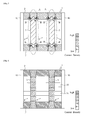
FIG. 1 illustrates a blank. -
FIG. 2 illustrates an energization heating process. -
FIG. 3 illustrates an electrode pair and equipotential lines generated between the electrode pair. -
FIG. 4 shows a conventional energization heating process. -
FIG. 5 shows a distribution of current density by the conventional energization heating process. -
FIG. 6 shows a distribution of current density by the present energization heating process. -
FIG. 7 depicts an alternative pair of electrodes and equipotential lines generated by the electrode pair. -
FIG. 8 illustrates an alternative embodiment of the blank. -
FIG. 9 illustrates an alternative energization heating process. -
FIG. 10 shows an electrode pair and equipotential lines generated by the electrode pair. - 1: blank, 10: electrode, 20: current path, 50: blank, 60: electrode pair, 70: group of current paths, 80: group of extension materials
- Referring to attached drawings, embodiments of a method for energization heating according to the present invention are described below.
In the energization heating method, blanks are energized and heated. After the energization heating, the blanks are delivered to die quenching process or hot press process. - During the die quenching process, the blanks, which have been heated above a predetermined temperature by the energization heating method of the present invention, are press-formed with the blanks rapidly quenched in a press mold.
The die quenching process is required to improve the quality of press-forming and of quenching. In other respects, the objective is to heat the blanks evenly such that the blanks to be delivered to the die quenching process are heated above the predetermined temperature where the qualities of press-forming and quenching are guaranteed.
Moreover, to reduce the number of process and the number of members, it is required to prepare the blanks ready to be used as a product through subsequent processes such as die quenching and trimming, that is, the blanks having different shapes from rectangular, and to directly transfer from the energization heating process to die quenching process.
The present invention provides a new energization heating technique solving the above problems, and the embodiments of the invention are described below. - Referring to
FIGS. 1 to 5 , an energization heating process S1 as a first embodiment of the energization heating method is described below, in which a blank 1 is energized and heated.
The blank 1, as a heating object in the energization heating process S1, is made of a material with conductivity and quenchability such as steel. The blank 1 is a plate having a "different shape."
The "different shape" means the shape different from rectangle that is used for the object to be heated in the conventional energization heating process. For instance, the different shape is a H-shape, a T-shape, or a holed shape that is obtained by trimming a rectangular part or integrating some parts, and the blank with such shape is used as a product after the die quenching process and trimming process.
Furthermore, a blank having rectangular shape, into which multiple parts with different resistances are integrated by laser welding or the like, is accounted as the different shape in the invention, because when energizing such blank, the current density varies in response to the electrical resistances of the multiple parts and it is difficult to provide the even heating distribution.
For the convenience of the explanation, the upper-lower direction and left-right direction of the blank 1 are defined as the upper-lower direction and left-right direction inFIG. 1 , respectively. - As shown in
FIG. 1 , the blank 1 has twolateral portions 2 and twovertical portions 3, and the ends of thevertical portions 3 are connected to the sides of thelateral portions 2, thereby integrated into one part.
Thelateral portions 2 are disposed in parallel and extended from one end to the opposite end of the blank 1 (in the left-right direction). Thevertical portions 3 are disposed in parallel and extended perpendicular to the left-right direction (in upper-lower direction). - The blank 1 has two
cutouts 4 at the both ends and asingle hole 5 at the center. Thecutouts 4 are disposed at the both opposite ends of the blank 1 and partially open the ends of the blank 1 rectangularly. Thehole 5 is a rectangular opening disposed at the center of the blank 1, surrounded by the portions of blank 1. The blank 1 is formed in the holed shape, in which thecutouts 4 and thehole 5 are removed from the rectangular shape. - The way of preparing the blank 1 is to trim the
cutouts 4 and thehole 5 from the rectangular plate or to combine thelateral portions 2 and the vertical portions 3 (prepare a tailored blank). - In the blank 1, prepared in the above-described manner, the connecting portions between the
lateral portions 2 and thevertical portions 3 are formed as a portion where the section area changes largely along the upper-lower direction perpendicular to the line from the left end to the right end, and as a portion where the section area changes largely along the left-right direction perpendicular to the line from the upper end to the lower end.
In other words, thecutouts 4 and thehole 5 make the blank 1 defined as the object having the large variation in section area along not only the left-right direction but also the upper-lower direction. - As illustrated in
FIG. 2 , in the energization heating process S1, a pair ofelectrodes 10 and multiplecurrent paths 20 are used to heat the blank 1.
Theelectrode pair 10 and thecurrent paths 20 are installed in an energization heating apparatus, to which the blank 1 is transferred and the energization heating process S1 is operated. - The
electrode pair 10 energizes the blank 1, and the one is used for a positive electrode and the other is used for a negative electrode. Theelectrode 10 is configured as a bar electrode having a longitudinal direction. Theelectrodes 10 are connected to a power source feeding the desired electric current, which applies current to the blank 1 through theelectrodes 10. In the blank 1, the current occurs from thepositive electrode 10 to thenegative electrode 10.
Theelectrode 10 is extended along the upper-lower direction and has the substantially same length as the blank 1. Theelectrode pair 10 is arranged to contact the both ends of thelateral portions 2 of the blank 1, that is, both ends in one direction of the two perpendicular directions. The energization direction of theelectrodes 10 is the left-right direction of the blank 1. - As shown in
FIG. 2 , theelectrode pair 10 includesmultiple connectors 11 provided with clamping structure for clamping the blank 1 from the thickness direction to secure the electrical connection with the blank 1 and thecurrent paths 20. Theconnector 11 includes clips to clamp the blank actuated by an air cylinder or a hydraulic cylinder, and the actuators switch the connecting/disconnecting between theelectrode 10 and the blank 1.
The clamping structure of theconnectors 11 contained in theelectrode pair 10 enables to maintain the contact between the blank 1 and theelectrodes 10. The clamping-type connectors reduce the influence of the deformation such as curving or roll back of the blank 1 that occurs during the energization heating and provide the uniform heating, compared with contact-type connectors. - If the blank 1 is configured in rectangular, the equipotential lines generated from the
positive electrode 10 to thenegative electrode 10 are shown inFIG. 3 . As shown inFIG. 3 , thebar electrodes 10 generate the equipotential lines parallel to the arrangement direction of theelectrodes 10.
Actually, the blank 1 has thecutouts 4 andhole 5 extended perpendicular to the equipotential lines between theelectrodes 10. In the embodiment, thecutouts 4 are spaces between theelectrodes 10 and the blank 1, and thehole 5 is space disposed inside of the blank 1, whereby these spaces act as non-energized areas and bring the variation in current density. -
FIG. 4 shows the conventional energization heating process, in which the blank 1 is heated by theelectrode pair 10.
The energization to the blank 1 is operated in one direction (from right to left in drawing) by using theelectrodes 10. There occurs current from the right side to the left side of thelateral portions 2 of the blank 1.
In the connecting area A where thelateral portions 2 and thevertical portion 3 are connected, the vertical length is sum of thelateral portions 2 and thevertical portion 3. Therefore, in the connecting area A, the section area perpendicular to the energization direction is locally large and there is a large variation in the current density, so that the electric current hardly passes through thevertical portions 3. - In detail,
FIG. 5 depicts the variations, shown in below (1) and (2). - (1) The connecting points B between the
lateral portion 2 and thevertical portion 3 make right angles, and the passing direction of the electric current extremely changes at the connecting point B. The electric current gathers to the connecting points B, so that the current density is high. - (2) The
lateral portions 2 are directly connected to theelectrodes 10, and the current density in thelateral portions 2 is high. The resistance at the current branch from thelateral portion 2 to thevertical portion 3 is large, and therefore the current density in thevertical portions 3 is low. - In the present embodiment, as shown in
FIG. 2 , theelectrode pair 10 energizes the blank in one direction (from right to left in drawing), and the electric current is bypassed through thecurrent paths 20 to thevertical portions 3. - The
current paths 20 are plate electrodes made of the material having lower electrical resistances than the blank 1 (e.g. when the blank 1 is made of steel, thecurrent path 20 is made of cupper or carbon), and are connected with the blank 1. Thecurrent paths 20 are extended along the left-right direction and arranged parallel to thelateral portions 2.
Thecurrent paths 20 are divided into three sections to connect theright electrode 10 with the rightvertical portion 3, the rightvertical portion 3 with the leftvertical portion 3 and the leftvertical portion 3 with the left electrode 10 (alternatively, the three sections are integrated as one member). The electrode paths bypass the non-energized areas between theelectrodes 10 defined by thecutouts 4 and thehole 5 of the blank 1 to which theelectrode pair 10 is connected.
Via thecurrent paths 20, the electric current passes from thepositive electrode 10 where the current density is high to thenegative electrode 10 through thevertical portions 3 where the current density is low.
In the embodiment, thecutouts 4 are the openings formed at the ends of the blank 1, so that the ends of thecurrent paths 20 disposed in thecutouts 4 are connected to theelectrodes 10. Thehole 5 is the opening surrounded by the blank 1, so that the ends of thecurrent paths 20 disposed in thehole 5 are connected to the blank 1. - As shown in
FIG. 6 , when energizing between theelectrodes 10, the electric passage from theelectrode 10 to thelateral portions 2 is bypassed via thecurrent paths 20, thereby passing the current to thevertical portions 3. Hence, the current density in thevertical portions 3 is increased, and the current density in the blank 1 is equalized.
In other words, arranging thecurrent paths 20 parallel to thelateral portions 2 makes the change of the section area along the direction perpendicular to the energization direction between theelectrodes 10 small, thereby improving the evenness of the current density in the blank 1.
As described above, due to thecurrent paths 20, the energization heating process S1 provides the improvement in evenness of the current density in the blank 1 and obtains even heating. Moreover, the energization heating process S1 improves the quality and productivity in the pressing or quenching after the heating process. - The
current paths 20 bypass the electric current from the high current-density area toward the low current-density area, i.e., thepositive electrode 10 to thevertical portions 3 which are separated from theelectrodes 10 by the non-energized areas (thecutouts 4 and the hole 5) and extended along the orthogonal direction with respect to the energization direction.
Due to this structure, overheat at the connecting points B as the intersections of the current passage is prevented, and the sufficient differential of electric potential occurs between the left and right ends of thevertical portions 3. Thecurrent paths 20 reduce the variation in the current density and contribute to the equation of the current density. - The
current paths 20 connect between the peripherals of the blank 1 defined by thecutouts 4 and thehole 5, which are extended perpendicular to the equipotential lines generated between theelectrodes 10.
Thus, thevertical portions 3, which are separated from theelectrodes 10 by the spaces and thus located as the low current-density areas, are energized by bypassing through thecurrent paths 20, thereby equalizing the current density in the blank. - The
current paths 20 are arranged orthogonal to thebar electrodes 10, namely the paths are extended in the left-right direction and the electrodes are extended in the upper-lower direction. That is, thecurrent paths 20 are extended perpendicular to the equipotential lines generated between theelectrodes 10.
The current density in thecurrent paths 20 is even, and the bypass though the current paths are efficiently done.
Moreover, theelectrodes 10 are configured as the bar electrodes extended in one direction, and therefore, if theelectrodes 10 are set parallel to the opposite sides of the blank 1, the large section areas are obtained with regard to the energization direction. Thus, the uniform equipotential lines are generated and the heating efficiency is improved. - The
current path 20 is made of the material that has lower resistance than the blank 1, so that the current density in thecurrent path 20 is higher than that in thelateral portions 2. As a result, the electric current applied from theelectrode 10 is smoothly led to thevertical portions 3 via thecurrent paths 20.
On the contrary, if thecurrent paths 20 have higher resistance than the blank 1, thecurrent paths 20 are more heated than the blank 1 by the energization, thereby degrading the heating efficiency. - It should be noted that the object to be heated by the energization heating process S1 is not limited to the blank 1. For example, the blank may be configured not only in H-shape, T-shape or rectangular with some holes inside, but also in rectangular shape, in which multiple different materials are combined and shows the current distribution due to the difference in electric resistances during the energization.
If the blank to be heated occurs the variation in current density therein when a pair of electrodes energizes from one end to the opposite end, the energization heating process S1 provides the uniform heating, in which the electric current is bypassed from the high current-density area to the low current-density area.
Moreover, the blank may be a steel pipe having varying diameter, and the energization heating process S1 is likewise applicable. - The energization direction of the energization heating process S1 is not limited to the above embodiment, and changeable in accordance with the shape of the blank 1 or heating conditions.
For example, when the upper-lower direction of the blank 1 is set as the energization direction, thecurrent paths 20 are arranged to connect thelateral portions 2 at the outer side of thevertical portions 3. In this case, the current density in the blank 1 is also equalized. - The
electrodes 10 used in the energization heating process S1 are the bar electrodes generating the even equipotential lines, and may be substituted by an electrode pair enabled to generate the even equipotential lines between the electrode pair.
For example, two pairs ofhemispherical electrodes 15 may work. The hemisphere electrode pairs 15 generate the equipotential lines shown inFIG. 7 , so that the number of the electrodes or the arrangement of the electrodes is adjusted to generate the desired equipotential lines, that is, parallel lines along the ends of the blank 1. - If the blank 1 has curved ends and the connecting portions to the
electrodes 10 are not straight, preparing additional electrode members corresponding to the shape of the connecting portions to the blank 1 provides the straight connection with theelectrodes 10.
That is to say, the end peripheries of the blank are not limited to the straight shapes as the blank 1, and the energization heating process S1 is applicable to the blanks with any end shapes. - As for the blank 1, each
current path 20 is preferably located to divide thevertical portion 3 into three in the upper-lower direction. The configuration such as arrangement or number of thecurrent paths 20 is selectable in response to the shape of the blank 1 to achieve the even current density in the blank 1.
In the other embodiment, the current paths may be configured as conductive wires, which connect the high-potential area to the low-potential area so that the electric current is bypassed from the high current-density area to the low current-density area.
Alternatively, the blank is heated without connected with the current paths, detecting the heating state by capturing the heat image or simulation, and the best mode for the current paths is selected and arranged according to the detection. - Referring to
FIGS. 8 to 10 , an energization heating process S2 as a second embodiment of the energization heating method is described below, in which a blank 50 is energized and heated.
For the convenience of the explanation, the upper-lower direction and left-right direction of the blank 50 are defined as the upper-lower direction and left-right direction inFIG. 8 , respectively. - The blank 50, as a heating object in the energization heating process S2, is made of a material with conductivity and quenchability such as steel. The blank 50 is a plate member having a "different shape."
As shown inFIG. 8 , the blank 50 has afirst portion 51, asecond portion 52 and athird portion 53, and the sides of thefirst portion 51 and thesecond portion 52 are connected to the ends of thethird portion 53, thereby integrated into one member.
Theseportions - The
first portion 51 is extended from one end (right end in drawings) of the two opposite ends of the blank 50 to the other end (left end in drawings). Thefirst portion 51 is straight portion extended along the left-right direction.
Thesecond portion 52 is extended from the one end (right end in drawings) of the blank 50 to the opposite end (left end in drawings). Thesecond portion 52 is curved downwardly from the one end (right end in drawings) to the other end (left end in drawings). At the one end (right end in drawings), thesecond portion 52 is separated from thefirst portion 51, and at the other end (left end in drawings), thesecond portion 52 is combined to thefirst portion 51.
Thethird portion 53 is extended substantially perpendicular to the direction from the one end to the other end and connected with the middle portions of thefirst portion 51 and thesecond portion 52. Thethird portion 53 is inclined against the upper-lower direction. - The blank 50 includes a
cutout 54 provided at the right end, acutout 55 provided at the left end and ahole 56 provided at the center. The chain-dotted line inFIG. 9 represents the outer line if the blank 50 is rectangular.
Thecutout 54 is an opening disposed at the right end of the blank 50, and has a trapezoidal shape. In the blank 50, the end periphery (left side) of thecutout 54 is formed as an inclined straight line.
Thecutout 55 is an opening disposed at the left upper portion of the blank 50. In the blank 50, the end periphery (right side) of thecutout 55 is formed as a curved line. Thecutout 55 makes the vertical length in the left side of the blank 50 shorter than that in the right side.
Thehole 56 is a rough square opening disposed at the center of the blank 50. In the blank 50, the right end line defined by thehole 56 is an inclined straight line and the upper side defined by the hole is a curved line. - The way of preparing the blank 50 is to trim the
cutouts hole 56 from the rectangular plate or to combine thefirst portion 51, thesecond portion 52 and the third portion 53 (prepare a tailored blank). - As illustrated in
FIG. 9 , in the energization heating process S2, a pair ofelectrodes 60, a group ofcurrent paths 70 and a group ofextension materials 80 are used to heat the blank 50.
The pair ofelectrodes 60 and the group ofcurrent paths 70 are installed in an energization heating apparatus, to which the blank 50 is transferred and the energization heating process S2 is operated. - The
electrode pair 60 energizes the blank 50. Theelectrode pair 60 consists of afirst electrode 61 connected to the one end of the blank 50 and asecond electrode 62 connected to the other end of the blank 50, and one of theelectrodes
Theelectrodes electrodes electrodes positive electrode 61 to thenegative electrode 62.
Theelectrode 61 is extended along the upper-lower direction and has the substantially same length as the right side of the blank 50. Theelectrode 62 is extended along the upper-lower direction and has the substantially same length as the left side of the blank 50. The length of theelectrode 61 is longer than that of theelectrode 62. - As shown in
FIG. 9 , theelectrodes multiple connectors 63 provided with clamping structure for clamping the blank 50 from the thickness direction to secure the electrical connection with the blank 50. Theconnector 63 includes clips to clamp the blank actuated by an air cylinder or a hydraulic cylinder, and the actuators switch the connecting/disconnecting between theelectrodes
The clamp structure of theconnector 63 contained in theelectrodes electrodes - If the blank 50 is configured as rectangular plate, the equipotential lines generated from the
positive electrode 61 to theearth electrode 62 are shown inFIG. 10 . As shown inFIG. 10 , thebar electrodes electrodes electrode 61 to the upper end of theelectrode 62 above theelectrode 62, that is, where theelectrodes
Actually, the blank 50 has thecutouts hole 56 arranged perpendicular to the equipotential lines between theelectrodes cutouts electrodes hole 56 is space disposed inside of the blank 50, whereby these spaces act as non-energized areas and bring the variation in current density. - In the embodiment, as shown in
FIG. 9 , theelectrode pair 60 energizes the blank in one direction (from right to left in drawing), and the electric current passes through the group ofcurrent paths 70 and the group ofextension electrodes 80 to thethird portion 53 bypassing thecutout 54 and thehole 56 and to theelectrode 62 bypassing thecutout 55 from the curved end of thesecond portion 62. - All of the group of
current paths 70 are plate electrodes made of the material having lower electrical resistance than the blank 50 (e.g. when the blank 50 is made of steel, the eachcurrent path 70 is made of cupper or carbon), and are connected with the blank 50. The group ofcurrent paths 70 is extended along the left-right direction.
As shown inFIG. 9 , the group ofcurrent paths 70 includes afirst path 71 connecting theelectrode 61 to the right side of thethird portion 53, asecond path 72 connecting the left side of thethird portion 53 to the right side of thesecond portion 52, and athird path 73 connecting the left side of thesecond portion 52 to theelectrode 62.
The firstcurrent path 71 is disposed at the space formed by thecutout 54 and arranged perpendicular to the equipotential lines generated between the pair ofelectrodes 60. The secondcurrent path 72 is disposed at the space formed by thehole 56 and arranged perpendicular to the equipotential lines generated between the pair ofelectrodes 60. Thecurrent path 73 is disposed at the space formed by thecutout 55 and arranged perpendicular to the equipotential lines generated between the pair ofelectrodes 60.
In the embodiment, "perpendicular to the equipotential lines" means to cross the equipotential line at right angle and at enough angle (e.g. above 45 degrees), and the "enough angle" is defined as the angle where flow of the electric current generating the equipotential lines is influenced by the current path crossing thereto.
The thirdcurrent path 73 containsfirst portions 73a extended in the left-right direction and asecond portion 73b connecting thefirst portions 73a to theelectrode 62 and extended in the upper-lower direction. Thefirst portions 73a and thesecond portion 73b are perpendicular to the equipotential lines generated between the pair ofelectrodes 60. In other words, thesecond portion 73b of thethird path 73 extends theelectrode 62 in the upper direction, whereby theelectrode 62 and thesecond portion 73b make the vertical electrode with the same length as theelectrode 61.
As described above, the group ofcurrent paths 70 bypasses the non-energized area formed by thecutouts hole 56 along the direction perpendicular to the equipotential lines between theelectrode pair 60. - All of the
extension materials 80 are made of the same materials as the blank 50 (steel or the like), and connected with the blank 50. The group ofextension materials 80 is extended along the left-right direction. The group ofextension materials 80 connects the blank 50 and the group ofcurrent paths 70 at the inclined sides and curved side of the blank. - As depicted in
FIG. 9 , the group ofextension materials 80 is formed such that the blank 50 is straightly connected to the group ofcurrent paths 70. That is, the ends of the group ofextension materials 80 are formed as straight lines at the connections to the group ofcurrent paths 70.
The clamping structures are used to electrically connect the group ofextension materials 80 to the group ofcurrent paths 70, and as described above, the straight connections between the group ofextension materials 80 and the group ofcurrent paths 70 make the clamping resistances reduced and improve the heating efficiency by means of the electric current passing through the group ofcurrent paths 70.
The clamping structures may be the same as theconnectors 11 installed in theelectrodes 10 as in the first embodiment. - As shown in
FIG. 9 , the group ofextension materials 80 includesfirst materials 81 connecting the firstcurrent path 71 to the right side of thethird portion 53,second materials 82 connecting the left side of thethird portion 53 to the secondcurrent path 72, athird material 83 connecting the secondcurrent path 72 to the right side of thesecond portion 52, andfourth materials 84 connecting the left curved side of thesecond portion 52 to the thirdcurrent path 73.
The way to connect the group ofextension materials 80 with the blank 50 is to prepare the blank 50 including such materials or to fix the materials to the blank 50 after preparing the blank 50. Regardless of the way to connect, theextension materials 80 are not used in the product and removed in the trimming process or the like after the energization heating process S2.
The number or arrangement of the extension materials (81, 82, 83 and 84) of the group ofextension materials 80 is not limited to the present embodiment. - In the energization heating process S2, the energization is operated with the group of
current paths 70, and therefore the current density in the blank 50 is equalized and the uniform heating is provided. Moreover, the energization heating process S2 improves the quality and productivity in the pressing or quenching after the process.
It should be noted that the second embodiment brings the same effects as the first embodiment. - Furthermore, in the present embodiment using the group of
extension materials 80 to connect the group ofcurrent paths 70 to the blank 50, the following effects are obtained.
The peripherals of thecutouts hole 56 formed as the spaces in the blank 50 contain the curved shape (the left side of the second portion 52) and the inclined shape to the energization direction by the electrode pair 60 (the both sides of the third portion 53). Therefore, if the group ofcurrent paths 70 is directly connected to the blank 50, there may be defects in the heating condition or the clamping condition. In the embodiment, the group ofextension materials 80 is formed with the blank 50 and the group ofcurrent paths 70 is connected to the blank 50 via the group ofextension materials 80, which improves the heating property, thereby providing the even heating. - In the present embodiment, the
electrode pair 60 includes theelectrode electrode 62 may have the same length as the maximum upper-lower length of the blank 50 (i.e., the electrode 61). In this case, the equipotential lines generate by theelectrode pair 60 is parallel to the arrangement direction of theelectrode pair 60. - The present invention is applicable to a technique of heating by energizing a blank, and particularly to the technique of evenly heating the blank, which causes a distribution of current density while energizing by using a single pair of electrodes.
Claims (7)
- A method for heating a blank by an energization using a pair of electrodes connected with two different ends of the blank, wherein
the blank has a space formed in a direction perpendicular to equipotential lines generated between the electrode pair, and
a current path is arranged at both ends of a periphery separated by the space in the direction perpendicular to the equipotential lines. - A method for heating a blank by an energization using a pair of electrodes connected with two different ends of the blank, wherein
the blank has a space formed in a direction perpendicular to equipotential lines generated between the electrode pair, and the space comprises: a first space formed at an end of the blank, opening the end of the blank; and a second space formed inside the blank,
current paths are arranged at both ends of peripheries separated by the first and second spaces in the direction perpendicular to the equipotential lines, and the current path connected to the first space is connected to the electrode. - The method according to claim 1 or 2, wherein
the electrode pair is configured as bar electrodes disposed in parallel, and connected to the two opposite ends of the blank, and
the current path is arranged perpendicular to the arrangement direction of the electrode pair. - The method according to one of claims 1 to 3, wherein
the current path is made of a material having lower electric resistance. - The method according to one of claims 1 to 4, wherein
the end periphery separated by the space in the blank, to which the current path is connected, is formed as an inclined line or a curved line, and
the current path is connected to the inclined or curved line of the blank via an extension material made of the same material as the blank and disposed perpendicular to the arrangement direction of the electrode pair. - The method according to claim 5, wherein
the blank comprises: a first portion extended straightly from one end to the opposite end of the blank; a second portion extended with curved shape from the one end to the opposite end of the blank and combined to the first portion at the opposite end; and a third portion connecting the middle portions of the first and second portions, and
one of the electrode pair to which the one end of the blank is connected is longer than the other one to which the opposite end of the blank is connected. - An apparatus for heating a blank by an energization using a pair of electrodes connected with two different ends of the blank, wherein
the blank has a space formed in a direction perpendicular to equipotential lines generated between the electrode pair,
a current path is provided with at both ends of a periphery separated by the space in the direction perpendicular to the equipotential lines,
the electrode pair is configured as bar electrodes disposed in parallel, and connected to the two opposite ends of the blank, and
the current path is arranged perpendicular to the arrangement direction of the electrode pair.
Applications Claiming Priority (1)
| Application Number | Priority Date | Filing Date | Title |
|---|---|---|---|
| PCT/JP2009/005412 WO2011045845A1 (en) | 2009-10-16 | 2009-10-16 | Energization heating method and energization heating device |
Publications (3)
| Publication Number | Publication Date |
|---|---|
| EP2489747A1 true EP2489747A1 (en) | 2012-08-22 |
| EP2489747A4 EP2489747A4 (en) | 2013-12-25 |
| EP2489747B1 EP2489747B1 (en) | 2017-03-15 |
Family
ID=43875905
Family Applications (1)
| Application Number | Title | Priority Date | Filing Date |
|---|---|---|---|
| EP09850387.3A Not-in-force EP2489747B1 (en) | 2009-10-16 | 2009-10-16 | Energization heating method and energization heating device |
Country Status (5)
| Country | Link |
|---|---|
| US (1) | US8866046B2 (en) |
| EP (1) | EP2489747B1 (en) |
| JP (1) | JP5403068B2 (en) |
| CN (1) | CN102575310B (en) |
| WO (1) | WO2011045845A1 (en) |
Cited By (2)
| Publication number | Priority date | Publication date | Assignee | Title |
|---|---|---|---|---|
| WO2015124604A1 (en) * | 2014-02-18 | 2015-08-27 | Gottfried Wilhelm Leibniz Universität Hannover | Method for conductively heating sheet metal, and heating device for carrying out said method |
| WO2016131501A1 (en) * | 2015-02-18 | 2016-08-25 | Gottfried Wilhelm Leibniz Universität Hannover | Method for conductively heating sheet metal, electrode, and heating device therefor |
Families Citing this family (10)
| Publication number | Priority date | Publication date | Assignee | Title |
|---|---|---|---|---|
| JP5790473B2 (en) * | 2011-12-14 | 2015-10-07 | トヨタ自動車株式会社 | Electric heating method and electric heating device |
| JP5880175B2 (en) * | 2012-03-15 | 2016-03-08 | マツダ株式会社 | Electric heating method and hot press molding method |
| JP6123089B2 (en) * | 2013-03-08 | 2017-05-10 | 高周波熱錬株式会社 | Electric heating method |
| JP6463911B2 (en) * | 2014-06-24 | 2019-02-06 | 高周波熱錬株式会社 | Heating method, heating apparatus, and method for producing press-molded product |
| TWI583797B (en) * | 2015-08-25 | 2017-05-21 | Nat Kaohsiung First Univ Of Science And Tech | Local heating device for plate and heating method thereof |
| CN106406379B (en) * | 2016-08-31 | 2018-04-10 | 兰州空间技术物理研究所 | A kind of temperature control device directly heated to being calibrated vacuum meter in vacuum chamber |
| JP2020093261A (en) * | 2017-03-30 | 2020-06-18 | 住友重機械工業株式会社 | Electric heating device |
| JP6902928B2 (en) | 2017-05-24 | 2021-07-14 | 住友重機械工業株式会社 | Energizing heating device and energizing heating method |
| CN107041022B (en) * | 2017-06-14 | 2023-03-28 | 福建工程学院 | Conductive blank conductive heating device |
| CN112484872B (en) * | 2020-12-08 | 2025-01-03 | 重庆江东机械有限责任公司 | Large current self-resistance heating device and method for variable cross-section blade blank |
Family Cites Families (8)
| Publication number | Priority date | Publication date | Assignee | Title |
|---|---|---|---|---|
| JPH044587A (en) * | 1990-04-20 | 1992-01-09 | Victor Co Of Japan Ltd | Heating method with current feed to electric resistor |
| JP4604364B2 (en) * | 2001-02-22 | 2011-01-05 | 住友金属工業株式会社 | Method and apparatus for hot pressing metal plate |
| DE10212820C1 (en) | 2002-03-22 | 2003-04-17 | Benteler Automobiltechnik Gmbh | Electrical resistance heating of a metal workpiece uses electrodes to pre-heat regions having a larger cross-section relative to the other regions to a defined temperature level before the entire workpiece is heated |
| JP2005131665A (en) | 2003-10-30 | 2005-05-26 | Komatsu Sanki Kk | Press-working method |
| US7714253B2 (en) | 2006-03-16 | 2010-05-11 | Noble Advanced Technologies, Inc. | Method and apparatus for the uniform resistance heating of articles |
| JP2008087001A (en) | 2006-09-29 | 2008-04-17 | Mazda Motor Corp | Processing method and processing apparatus for plate workpiece |
| JP4563469B2 (en) | 2008-05-16 | 2010-10-13 | トヨタ自動車株式会社 | Press processing method and press processed product |
| JP6010730B2 (en) * | 2009-05-29 | 2016-10-19 | 日産自動車株式会社 | High-strength molded article by high ductility die quench and method for producing the same |
-
2009
- 2009-10-16 JP JP2011543895A patent/JP5403068B2/en not_active Expired - Fee Related
- 2009-10-16 EP EP09850387.3A patent/EP2489747B1/en not_active Not-in-force
- 2009-10-16 WO PCT/JP2009/005412 patent/WO2011045845A1/en not_active Ceased
- 2009-10-16 US US13/501,112 patent/US8866046B2/en not_active Expired - Fee Related
- 2009-10-16 CN CN2009801619783A patent/CN102575310B/en not_active Expired - Fee Related
Cited By (3)
| Publication number | Priority date | Publication date | Assignee | Title |
|---|---|---|---|---|
| WO2015124604A1 (en) * | 2014-02-18 | 2015-08-27 | Gottfried Wilhelm Leibniz Universität Hannover | Method for conductively heating sheet metal, and heating device for carrying out said method |
| JP2018508934A (en) * | 2014-02-18 | 2018-03-29 | ゴットフリート・ビルヘルム・ライプニツ・ウニベルジテート・ハノーバーGottfried Wilhelm Leibniz Universitaet Hannover | Method for conductive heating of metal sheet, electrode and heating apparatus therefor |
| WO2016131501A1 (en) * | 2015-02-18 | 2016-08-25 | Gottfried Wilhelm Leibniz Universität Hannover | Method for conductively heating sheet metal, electrode, and heating device therefor |
Also Published As
| Publication number | Publication date |
|---|---|
| CN102575310B (en) | 2013-11-20 |
| JPWO2011045845A1 (en) | 2013-03-04 |
| CN102575310A (en) | 2012-07-11 |
| US8866046B2 (en) | 2014-10-21 |
| WO2011045845A1 (en) | 2011-04-21 |
| JP5403068B2 (en) | 2014-01-29 |
| EP2489747A4 (en) | 2013-12-25 |
| US20120193336A1 (en) | 2012-08-02 |
| EP2489747B1 (en) | 2017-03-15 |
Similar Documents
| Publication | Publication Date | Title |
|---|---|---|
| US8866046B2 (en) | Energization heating method and energization heating device | |
| EP3209949B1 (en) | Heater with integrated temperature sensor | |
| DE102013200428A1 (en) | MATERIALS AND METHOD FOR CONNECTING BATTERY CELL CONNECTIONS AND INTERCONNECTION COMBINATION RAILS | |
| US20150344986A1 (en) | Heat treatment apparatus for hot stamping and forming method using the same | |
| KR101904839B1 (en) | Apparatus and method for heating a blank for hot stamping | |
| DE102014106868A1 (en) | A blank forming apparatus using direct electric heating and a method of producing a blank | |
| JP2014013184A (en) | Cantilever type probe assembly and probe card or probe unit equipped with the same | |
| US9127886B2 (en) | Multistage furnace system | |
| JP2013244507A (en) | Electric heating method of press-molded article, electric heating device used therefor, and pressed product | |
| JP6679595B2 (en) | METHOD OF CONDUCTIVE HEATING OF METAL SHEET, ELECTRODE AND HEATING DEVICE FOR THE SAME | |
| US20190076971A1 (en) | Apparatus and method for manufacturing heat exchanger for vehicle | |
| US8989565B2 (en) | Multistage furnace | |
| EP3864262B1 (en) | Apparatus for exhaust gas treatment | |
| JP2011189402A (en) | Resistance heating method of metal sheet | |
| DE102005031081A1 (en) | Bipolar plate for electrochemical application, has passage opening guiding fuel and/or oxidizer and insertion unit arranged between top layers in area of opening, where point-forces are induced in two-dimensional manner by unit | |
| DE102015223303B4 (en) | INDUCTION HEATING DEVICE OF A BLANK PART | |
| DE102014019092A1 (en) | Cell holder, cell block and electric battery | |
| US9765677B2 (en) | Catalyst casing-integrated exhaust manifold and method for manufacturing same | |
| DE102012111817A1 (en) | Electrical energy storage i.e. traction battery, for e.g. hybrid vehicle, has battery cells comprising cell terminal with positive pole and negative pole, and cooling device for cooling terminal and/or positive pole and/or negative pole | |
| KR101574774B1 (en) | Press die for electroplasticity forming | |
| WO2011026779A2 (en) | Method for temperature control of fuel cell or electrolytic converter stacks | |
| DE102009051949A1 (en) | Thermoelectric generator module and exhaust gas component | |
| DE102019121576A1 (en) | Method for producing a press-hardened sheet metal component and heating device | |
| CN106211389B (en) | The resistive heating system of unimach | |
| JP2012024836A (en) | Electric heating method |
Legal Events
| Date | Code | Title | Description |
|---|---|---|---|
| PUAI | Public reference made under article 153(3) epc to a published international application that has entered the european phase |
Free format text: ORIGINAL CODE: 0009012 |
|
| 17P | Request for examination filed |
Effective date: 20120426 |
|
| AK | Designated contracting states |
Kind code of ref document: A1 Designated state(s): AT BE BG CH CY CZ DE DK EE ES FI FR GB GR HR HU IE IS IT LI LT LU LV MC MK MT NL NO PL PT RO SE SI SK SM TR |
|
| DAX | Request for extension of the european patent (deleted) | ||
| RAP1 | Party data changed (applicant data changed or rights of an application transferred) |
Owner name: TOYOTA JIDOSHA KABUSHIKI KAISHA |
|
| A4 | Supplementary search report drawn up and despatched |
Effective date: 20131126 |
|
| RIC1 | Information provided on ipc code assigned before grant |
Ipc: B21D 24/00 20060101ALI20131120BHEP Ipc: C21D 9/00 20060101ALI20131120BHEP Ipc: C21D 1/40 20060101AFI20131120BHEP Ipc: H05B 3/00 20060101ALI20131120BHEP |
|
| RIN1 | Information on inventor provided before grant (corrected) |
Inventor name: YAMANISHI, KAZUOMI, Inventor name: MATSUMOTO, SHIN'ICHIROH, |
|
| 17Q | First examination report despatched |
Effective date: 20150703 |
|
| GRAP | Despatch of communication of intention to grant a patent |
Free format text: ORIGINAL CODE: EPIDOSNIGR1 |
|
| RIC1 | Information provided on ipc code assigned before grant |
Ipc: H05B 3/00 20060101ALI20160902BHEP Ipc: C21D 9/00 20060101ALI20160902BHEP Ipc: C21D 1/40 20060101AFI20160902BHEP Ipc: B21D 37/16 20060101ALI20160902BHEP |
|
| INTG | Intention to grant announced |
Effective date: 20160928 |
|
| STAA | Information on the status of an ep patent application or granted ep patent |
Free format text: STATUS: GRANT OF PATENT IS INTENDED |
|
| GRAS | Grant fee paid |
Free format text: ORIGINAL CODE: EPIDOSNIGR3 |
|
| GRAA | (expected) grant |
Free format text: ORIGINAL CODE: 0009210 |
|
| STAA | Information on the status of an ep patent application or granted ep patent |
Free format text: STATUS: THE PATENT HAS BEEN GRANTED |
|
| AK | Designated contracting states |
Kind code of ref document: B1 Designated state(s): AT BE BG CH CY CZ DE DK EE ES FI FR GB GR HR HU IE IS IT LI LT LU LV MC MK MT NL NO PL PT RO SE SI SK SM TR |
|
| REG | Reference to a national code |
Ref country code: CH Ref legal event code: EP Ref country code: GB Ref legal event code: FG4D |
|
| REG | Reference to a national code |
Ref country code: IE Ref legal event code: FG4D |
|
| REG | Reference to a national code |
Ref country code: AT Ref legal event code: REF Ref document number: 875644 Country of ref document: AT Kind code of ref document: T Effective date: 20170415 |
|
| REG | Reference to a national code |
Ref country code: DE Ref legal event code: R096 Ref document number: 602009044859 Country of ref document: DE |
|
| REG | Reference to a national code |
Ref country code: DE Ref legal event code: R084 Ref document number: 602009044859 Country of ref document: DE |
|
| REG | Reference to a national code |
Ref country code: NL Ref legal event code: MP Effective date: 20170315 |
|
| REG | Reference to a national code |
Ref country code: LT Ref legal event code: MG4D |
|
| PG25 | Lapsed in a contracting state [announced via postgrant information from national office to epo] |
Ref country code: GR Free format text: LAPSE BECAUSE OF FAILURE TO SUBMIT A TRANSLATION OF THE DESCRIPTION OR TO PAY THE FEE WITHIN THE PRESCRIBED TIME-LIMIT Effective date: 20170616 Ref country code: HR Free format text: LAPSE BECAUSE OF FAILURE TO SUBMIT A TRANSLATION OF THE DESCRIPTION OR TO PAY THE FEE WITHIN THE PRESCRIBED TIME-LIMIT Effective date: 20170315 Ref country code: NO Free format text: LAPSE BECAUSE OF FAILURE TO SUBMIT A TRANSLATION OF THE DESCRIPTION OR TO PAY THE FEE WITHIN THE PRESCRIBED TIME-LIMIT Effective date: 20170615 Ref country code: FI Free format text: LAPSE BECAUSE OF FAILURE TO SUBMIT A TRANSLATION OF THE DESCRIPTION OR TO PAY THE FEE WITHIN THE PRESCRIBED TIME-LIMIT Effective date: 20170315 Ref country code: LT Free format text: LAPSE BECAUSE OF FAILURE TO SUBMIT A TRANSLATION OF THE DESCRIPTION OR TO PAY THE FEE WITHIN THE PRESCRIBED TIME-LIMIT Effective date: 20170315 |
|
| REG | Reference to a national code |
Ref country code: AT Ref legal event code: MK05 Ref document number: 875644 Country of ref document: AT Kind code of ref document: T Effective date: 20170315 |
|
| PG25 | Lapsed in a contracting state [announced via postgrant information from national office to epo] |
Ref country code: BG Free format text: LAPSE BECAUSE OF FAILURE TO SUBMIT A TRANSLATION OF THE DESCRIPTION OR TO PAY THE FEE WITHIN THE PRESCRIBED TIME-LIMIT Effective date: 20170615 Ref country code: SE Free format text: LAPSE BECAUSE OF FAILURE TO SUBMIT A TRANSLATION OF THE DESCRIPTION OR TO PAY THE FEE WITHIN THE PRESCRIBED TIME-LIMIT Effective date: 20170315 Ref country code: LV Free format text: LAPSE BECAUSE OF FAILURE TO SUBMIT A TRANSLATION OF THE DESCRIPTION OR TO PAY THE FEE WITHIN THE PRESCRIBED TIME-LIMIT Effective date: 20170315 |
|
| PG25 | Lapsed in a contracting state [announced via postgrant information from national office to epo] |
Ref country code: NL Free format text: LAPSE BECAUSE OF FAILURE TO SUBMIT A TRANSLATION OF THE DESCRIPTION OR TO PAY THE FEE WITHIN THE PRESCRIBED TIME-LIMIT Effective date: 20170315 |
|
| PG25 | Lapsed in a contracting state [announced via postgrant information from national office to epo] |
Ref country code: IT Free format text: LAPSE BECAUSE OF FAILURE TO SUBMIT A TRANSLATION OF THE DESCRIPTION OR TO PAY THE FEE WITHIN THE PRESCRIBED TIME-LIMIT Effective date: 20170315 Ref country code: ES Free format text: LAPSE BECAUSE OF FAILURE TO SUBMIT A TRANSLATION OF THE DESCRIPTION OR TO PAY THE FEE WITHIN THE PRESCRIBED TIME-LIMIT Effective date: 20170315 Ref country code: CZ Free format text: LAPSE BECAUSE OF FAILURE TO SUBMIT A TRANSLATION OF THE DESCRIPTION OR TO PAY THE FEE WITHIN THE PRESCRIBED TIME-LIMIT Effective date: 20170315 Ref country code: AT Free format text: LAPSE BECAUSE OF FAILURE TO SUBMIT A TRANSLATION OF THE DESCRIPTION OR TO PAY THE FEE WITHIN THE PRESCRIBED TIME-LIMIT Effective date: 20170315 Ref country code: RO Free format text: LAPSE BECAUSE OF FAILURE TO SUBMIT A TRANSLATION OF THE DESCRIPTION OR TO PAY THE FEE WITHIN THE PRESCRIBED TIME-LIMIT Effective date: 20170315 Ref country code: SK Free format text: LAPSE BECAUSE OF FAILURE TO SUBMIT A TRANSLATION OF THE DESCRIPTION OR TO PAY THE FEE WITHIN THE PRESCRIBED TIME-LIMIT Effective date: 20170315 Ref country code: EE Free format text: LAPSE BECAUSE OF FAILURE TO SUBMIT A TRANSLATION OF THE DESCRIPTION OR TO PAY THE FEE WITHIN THE PRESCRIBED TIME-LIMIT Effective date: 20170315 |
|
| PG25 | Lapsed in a contracting state [announced via postgrant information from national office to epo] |
Ref country code: PT Free format text: LAPSE BECAUSE OF FAILURE TO SUBMIT A TRANSLATION OF THE DESCRIPTION OR TO PAY THE FEE WITHIN THE PRESCRIBED TIME-LIMIT Effective date: 20170717 Ref country code: IS Free format text: LAPSE BECAUSE OF FAILURE TO SUBMIT A TRANSLATION OF THE DESCRIPTION OR TO PAY THE FEE WITHIN THE PRESCRIBED TIME-LIMIT Effective date: 20170715 Ref country code: PL Free format text: LAPSE BECAUSE OF FAILURE TO SUBMIT A TRANSLATION OF THE DESCRIPTION OR TO PAY THE FEE WITHIN THE PRESCRIBED TIME-LIMIT Effective date: 20170315 Ref country code: SM Free format text: LAPSE BECAUSE OF FAILURE TO SUBMIT A TRANSLATION OF THE DESCRIPTION OR TO PAY THE FEE WITHIN THE PRESCRIBED TIME-LIMIT Effective date: 20170315 |
|
| REG | Reference to a national code |
Ref country code: DE Ref legal event code: R097 Ref document number: 602009044859 Country of ref document: DE |
|
| PLBE | No opposition filed within time limit |
Free format text: ORIGINAL CODE: 0009261 |
|
| STAA | Information on the status of an ep patent application or granted ep patent |
Free format text: STATUS: NO OPPOSITION FILED WITHIN TIME LIMIT |
|
| PG25 | Lapsed in a contracting state [announced via postgrant information from national office to epo] |
Ref country code: DK Free format text: LAPSE BECAUSE OF FAILURE TO SUBMIT A TRANSLATION OF THE DESCRIPTION OR TO PAY THE FEE WITHIN THE PRESCRIBED TIME-LIMIT Effective date: 20170315 |
|
| 26N | No opposition filed |
Effective date: 20171218 |
|
| PG25 | Lapsed in a contracting state [announced via postgrant information from national office to epo] |
Ref country code: SI Free format text: LAPSE BECAUSE OF FAILURE TO SUBMIT A TRANSLATION OF THE DESCRIPTION OR TO PAY THE FEE WITHIN THE PRESCRIBED TIME-LIMIT Effective date: 20170315 |
|
| PG25 | Lapsed in a contracting state [announced via postgrant information from national office to epo] |
Ref country code: MC Free format text: LAPSE BECAUSE OF FAILURE TO SUBMIT A TRANSLATION OF THE DESCRIPTION OR TO PAY THE FEE WITHIN THE PRESCRIBED TIME-LIMIT Effective date: 20170315 |
|
| REG | Reference to a national code |
Ref country code: CH Ref legal event code: PL |
|
| GBPC | Gb: european patent ceased through non-payment of renewal fee |
Effective date: 20171016 |
|
| REG | Reference to a national code |
Ref country code: IE Ref legal event code: MM4A |
|
| REG | Reference to a national code |
Ref country code: FR Ref legal event code: ST Effective date: 20180629 |
|
| PG25 | Lapsed in a contracting state [announced via postgrant information from national office to epo] |
Ref country code: GB Free format text: LAPSE BECAUSE OF NON-PAYMENT OF DUE FEES Effective date: 20171016 Ref country code: CH Free format text: LAPSE BECAUSE OF NON-PAYMENT OF DUE FEES Effective date: 20171031 Ref country code: LU Free format text: LAPSE BECAUSE OF NON-PAYMENT OF DUE FEES Effective date: 20171016 Ref country code: LI Free format text: LAPSE BECAUSE OF NON-PAYMENT OF DUE FEES Effective date: 20171031 |
|
| REG | Reference to a national code |
Ref country code: BE Ref legal event code: MM Effective date: 20171031 |
|
| PG25 | Lapsed in a contracting state [announced via postgrant information from national office to epo] |
Ref country code: FR Free format text: LAPSE BECAUSE OF NON-PAYMENT OF DUE FEES Effective date: 20171031 Ref country code: BE Free format text: LAPSE BECAUSE OF NON-PAYMENT OF DUE FEES Effective date: 20171031 |
|
| PG25 | Lapsed in a contracting state [announced via postgrant information from national office to epo] |
Ref country code: MT Free format text: LAPSE BECAUSE OF NON-PAYMENT OF DUE FEES Effective date: 20171016 |
|
| PG25 | Lapsed in a contracting state [announced via postgrant information from national office to epo] |
Ref country code: IE Free format text: LAPSE BECAUSE OF NON-PAYMENT OF DUE FEES Effective date: 20171016 |
|
| PG25 | Lapsed in a contracting state [announced via postgrant information from national office to epo] |
Ref country code: HU Free format text: LAPSE BECAUSE OF FAILURE TO SUBMIT A TRANSLATION OF THE DESCRIPTION OR TO PAY THE FEE WITHIN THE PRESCRIBED TIME-LIMIT; INVALID AB INITIO Effective date: 20091016 |
|
| PG25 | Lapsed in a contracting state [announced via postgrant information from national office to epo] |
Ref country code: CY Free format text: LAPSE BECAUSE OF NON-PAYMENT OF DUE FEES Effective date: 20170315 |
|
| PG25 | Lapsed in a contracting state [announced via postgrant information from national office to epo] |
Ref country code: MK Free format text: LAPSE BECAUSE OF FAILURE TO SUBMIT A TRANSLATION OF THE DESCRIPTION OR TO PAY THE FEE WITHIN THE PRESCRIBED TIME-LIMIT Effective date: 20170315 |
|
| PG25 | Lapsed in a contracting state [announced via postgrant information from national office to epo] |
Ref country code: TR Free format text: LAPSE BECAUSE OF FAILURE TO SUBMIT A TRANSLATION OF THE DESCRIPTION OR TO PAY THE FEE WITHIN THE PRESCRIBED TIME-LIMIT Effective date: 20170315 |
|
| PGFP | Annual fee paid to national office [announced via postgrant information from national office to epo] |
Ref country code: DE Payment date: 20210908 Year of fee payment: 13 |
|
| REG | Reference to a national code |
Ref country code: DE Ref legal event code: R119 Ref document number: 602009044859 Country of ref document: DE |
|
| PG25 | Lapsed in a contracting state [announced via postgrant information from national office to epo] |
Ref country code: DE Free format text: LAPSE BECAUSE OF NON-PAYMENT OF DUE FEES Effective date: 20230503 |