EP2488900B1 - Hinge mechanism for a fluid filled lens assembly - Google Patents
Hinge mechanism for a fluid filled lens assembly Download PDFInfo
- Publication number
- EP2488900B1 EP2488900B1 EP10824198.5A EP10824198A EP2488900B1 EP 2488900 B1 EP2488900 B1 EP 2488900B1 EP 10824198 A EP10824198 A EP 10824198A EP 2488900 B1 EP2488900 B1 EP 2488900B1
- Authority
- EP
- European Patent Office
- Prior art keywords
- hinge
- fluid
- temple arm
- lens assembly
- filled lens
- Prior art date
- Legal status (The legal status is an assumption and is not a legal conclusion. Google has not performed a legal analysis and makes no representation as to the accuracy of the status listed.)
- Not-in-force
Links
Images


Classifications
-
- G—PHYSICS
- G02—OPTICS
- G02B—OPTICAL ELEMENTS, SYSTEMS OR APPARATUS
- G02B3/00—Simple or compound lenses
- G02B3/12—Fluid-filled or evacuated lenses
- G02B3/14—Fluid-filled or evacuated lenses of variable focal length
-
- G—PHYSICS
- G02—OPTICS
- G02C—SPECTACLES; SUNGLASSES OR GOGGLES INSOFAR AS THEY HAVE THE SAME FEATURES AS SPECTACLES; CONTACT LENSES
- G02C7/00—Optical parts
- G02C7/02—Lenses; Lens systems ; Methods of designing lenses
- G02C7/08—Auxiliary lenses; Arrangements for varying focal length
- G02C7/081—Ophthalmic lenses with variable focal length
- G02C7/085—Fluid-filled lenses, e.g. electro-wetting lenses
-
- G—PHYSICS
- G02—OPTICS
- G02B—OPTICAL ELEMENTS, SYSTEMS OR APPARATUS
- G02B3/00—Simple or compound lenses
- G02B3/12—Fluid-filled or evacuated lenses
-
- G—PHYSICS
- G02—OPTICS
- G02C—SPECTACLES; SUNGLASSES OR GOGGLES INSOFAR AS THEY HAVE THE SAME FEATURES AS SPECTACLES; CONTACT LENSES
- G02C1/00—Assemblies of lenses with bridges or browbars
-
- G—PHYSICS
- G02—OPTICS
- G02C—SPECTACLES; SUNGLASSES OR GOGGLES INSOFAR AS THEY HAVE THE SAME FEATURES AS SPECTACLES; CONTACT LENSES
- G02C5/00—Constructions of non-optical parts
-
- G—PHYSICS
- G02—OPTICS
- G02C—SPECTACLES; SUNGLASSES OR GOGGLES INSOFAR AS THEY HAVE THE SAME FEATURES AS SPECTACLES; CONTACT LENSES
- G02C5/00—Constructions of non-optical parts
- G02C5/001—Constructions of non-optical parts specially adapted for particular purposes, not otherwise provided for or not fully classifiable according to technical characteristics, e.g. therapeutic glasses
-
- G—PHYSICS
- G02—OPTICS
- G02C—SPECTACLES; SUNGLASSES OR GOGGLES INSOFAR AS THEY HAVE THE SAME FEATURES AS SPECTACLES; CONTACT LENSES
- G02C5/00—Constructions of non-optical parts
- G02C5/14—Side-members
-
- G—PHYSICS
- G02—OPTICS
- G02C—SPECTACLES; SUNGLASSES OR GOGGLES INSOFAR AS THEY HAVE THE SAME FEATURES AS SPECTACLES; CONTACT LENSES
- G02C5/00—Constructions of non-optical parts
- G02C5/14—Side-members
- G02C5/146—Side-members having special front end
-
- G—PHYSICS
- G02—OPTICS
- G02C—SPECTACLES; SUNGLASSES OR GOGGLES INSOFAR AS THEY HAVE THE SAME FEATURES AS SPECTACLES; CONTACT LENSES
- G02C5/00—Constructions of non-optical parts
- G02C5/14—Side-members
- G02C5/16—Side-members resilient or with resilient parts
-
- G—PHYSICS
- G02—OPTICS
- G02C—SPECTACLES; SUNGLASSES OR GOGGLES INSOFAR AS THEY HAVE THE SAME FEATURES AS SPECTACLES; CONTACT LENSES
- G02C5/00—Constructions of non-optical parts
- G02C5/22—Hinges
-
- G—PHYSICS
- G02—OPTICS
- G02C—SPECTACLES; SUNGLASSES OR GOGGLES INSOFAR AS THEY HAVE THE SAME FEATURES AS SPECTACLES; CONTACT LENSES
- G02C5/00—Constructions of non-optical parts
- G02C5/22—Hinges
- G02C5/2218—Resilient hinges
- G02C5/2254—Resilient hinges comprising elastic means other than coil spring
-
- G—PHYSICS
- G02—OPTICS
- G02C—SPECTACLES; SUNGLASSES OR GOGGLES INSOFAR AS THEY HAVE THE SAME FEATURES AS SPECTACLES; CONTACT LENSES
- G02C7/00—Optical parts
-
- G—PHYSICS
- G02—OPTICS
- G02C—SPECTACLES; SUNGLASSES OR GOGGLES INSOFAR AS THEY HAVE THE SAME FEATURES AS SPECTACLES; CONTACT LENSES
- G02C7/00—Optical parts
- G02C7/02—Lenses; Lens systems ; Methods of designing lenses
- G02C7/08—Auxiliary lenses; Arrangements for varying focal length
-
- G—PHYSICS
- G02—OPTICS
- G02C—SPECTACLES; SUNGLASSES OR GOGGLES INSOFAR AS THEY HAVE THE SAME FEATURES AS SPECTACLES; CONTACT LENSES
- G02C2200/00—Generic mechanical aspects applicable to one or more of the groups G02C1/00 - G02C5/00 and G02C9/00 - G02C13/00 and their subgroups
- G02C2200/12—Frame or frame portions made from sheet type material
-
- G—PHYSICS
- G02—OPTICS
- G02C—SPECTACLES; SUNGLASSES OR GOGGLES INSOFAR AS THEY HAVE THE SAME FEATURES AS SPECTACLES; CONTACT LENSES
- G02C2200/00—Generic mechanical aspects applicable to one or more of the groups G02C1/00 - G02C5/00 and G02C9/00 - G02C13/00 and their subgroups
- G02C2200/22—Leaf spring
Definitions
- Embodiments of the present invention relate to fluid-filled lenses and in particular to variable fluid-filled lenses.
- Fluid lenses have also been proposed for ophthalmic applications (see, e.g., U.S. Patent No. 7,085,065 ).
- advantages of fluid lenses such as a wide dynamic range, ability to provide adaptive correction, robustness, and low cost have to be balanced against limitations in aperture size, possibility of leakage, and consistency in performance.
- the '065 patent for example, has disclosed several improvements and embodiments directed towards effective containment of the fluid in the fluid lens to be used in ophthalmic applications, although not limited to them (see, e.g., U.S. Patent No. 6,618,208 ).
- Power adjustment in fluid lenses has been effected by injecting additional fluid into a lens cavity, by electrowetting, application of ultrasonic impulse, and by utilizing swelling forces in a cross-linked polymer upon introduction of a swelling agent such as water.
- US 2,576,581 discloses polyfocal spectacles having a liquid expansible variable diopter lens in communication with a collapsible reservoir which is expanded or compressed through the action of a pressure plate adhesively secured to one side of the reservoir.
- a hinge for a fluid-filled lens assembly as set out in claim 1.
- the hinge for a fluid-filled lens assembly includes a base having a first end configured to connect to a temple arm of the lens assembly and a second end configured to connect to a frame of the lens assembly, wherein the base includes a gap that is shaped to allow for tubing to pass from the first end to the second end of the base.
- the first end of the base includes a cammed surface configured to engage a surface of the temple arm.
- first and second ends of the base are configured to flex around a rotation axis of the hinge.
- a fluid-filled lens assembly comprises: a temple arm; a reservoir disposed within the housing; a frame; a fluid-filled lens disposed within the frame; tubing connecting the reservoir to the fluid-filled lens; and a hinge attached to the temple arm and to the frame.
- the hinge includes a base having a gap that is shaped to allow for tubing to pass from a first end to a second end of the base.
- references in the specification to "one embodiment,” “an embodiment,” “an example embodiment,” etc. indicate that the embodiment described can include a particular feature, structure, or characteristic, but every embodiment may not necessarily include the particular feature, structure, or characteristic. Moreover, such phrases do not necessarily refer to the same embodiment. Further, when a particular feature, structure, or characteristic is described in connection with an embodiment, it would be within the knowledge of one skilled in the art to affect such feature, structure or characteristic in connection with other embodiments whether or not explicitly described.
- Fluid lenses have important advantages over conventional means of vision correction, such as rigid lenses and contact lenses.
- an individual who requires an additional positive power correction to view near objects can be fitted with a fluid lens of base power matching the distance prescription. The user can then adjust the fluid lens to obtain additional positive power correction as needed to view objects at intermediate and other distances.
- fluid lenses can be adjusted continuously over a desired power range by the wearer.
- the wearer can adjust the power to precisely match the refractive error for a particular object distance in a particular light environment.
- fluid lenses allow adjustment of power to compensate for alteration of the natural depth of focus of the eye that depends on the wearer's pupil size, which is in turn dependent on the ambient light level.
- the optical power of the fluid filled lens may be adjusted by moving an actuator attached to a reservoir located in a temple arm of the eyeglass frame.
- the reservoir is attached to the fluid filled lens via a connecting tube.
- Moving the actuator a first way compresses the reservoir and pushes fluid into the fluid lens.
- Moving the actuator a second way allows the reservoir to expand and pull fluid from the fluid lens. The compression and expansion of the reservoir changes the optical power of the fluid filled lens.
- one or more fluid lenses may be provided, each with its own actuation system, so that a lens for each eye may be adjusted independently.
- a fluid filled lens assembly according to an embodiment of the present invention provides ample space within the temple and end piece for the connecting tube to bend without kinking.
- the entire hinge mechanism may be located within the volume of the temple arm and frame.
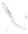
- FIG. 1 illustrates a perspective view of a caliper actuator assembly 100, according to an embodiment of the present invention.
- Caliper actuator assembly 100 includes temple cover 110, which includes a hollow outer portion and a hollow inner portion formed together to enclose additional pieces of caliper actuator assembly 100. Distal end 160 of temple cover 110 is shaped to fit over a wearer's ear.
- Caliper actuator assembly 100 further includes temple chassis 120, wheel 130, and slider 140. In an embodiment, wheel 130 and slider 140 are longitudinally slidably disposed within temple chassis 120.
- Caliper actuator assembly 100 operates to compress reservoir 150 and transfer fluid between reservoir 150 and a fluid lens (not shown). The compressing force may be applied in various ways, such as for example, by rotating wheel 130 or by translating the wheel along a slot. Additional methods of applying compressing force are also described herein. The compression of reservoir 150 may be effected either by compressing reservoir 150 in a vertical or horizontal direction against a ceiling or inner wall of temple chassis 120, as described in detail below.
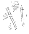
- FIG. 2 illustrates an exploded perspective view of an embodiment of caliper actuator assembly 100.
- slider subassembly 295 (described below with respect to FIGs. 3-4 ) is configured to translate along one or more of temple cover 110 and temple chassis 120 in order to compress reservoir 150.
- a user rotates wheel 130, which moves slider block 255, which in turn compresses a relatively stiff metal plate, such as compression arm 270, that is in contact with a first side surface 265 of reservoir 150.
- a second side surface (not shown) of reservoir 150 is placed against inner wall 285 of temple chassis 120, a portion of temple cover 110, or any other suitable surface.
- Slider 140 presses against compression arm 270, which compresses reservoir 150 in a controllable manner.
- the length of the lateral movement of wheel 130 is proportional to the magnitude of compression of the compression arm, and is proportional to the magnitude of compression of the reservoir. Further description and additional embodiments of the actuator are described in U.S. Appl. No. 12/904,720 .
- wheel 130 has a knurled edge in order to provide secure contact with the finger of the user as well more precise control over the translation of wheel 130.
- Lens module 200 is connected via outlet port 245 to a connecting tube (not shown), which is connected to reservoir 150.
- Lens module 200 may further include a flexible back surface provided by, for example, a flexible membrane (not shown) stretched flat over the edge of rigid optical lens.
- the membrane may be inflated through the addition of a fluid in communication with reservoir 150.
- the connecting tube delivers fluid from lens module 200 to reservoir 150 and vice versa.
- the connecting tube is designed to be relatively impermeable to the fluid contained therein.
- the connecting tube is configured to allow a minimum flow rate at all times in order to ensure a minimum speed of response to the user moving wheel 130 in order to change the optical power of fluid filled lens module 200.
- the connecting tube is connected at one end to outlet port 245 of lens module 200 and at the other end to reservoir 150.
- the overall assembly including the lens module 200, the connecting tube, and reservoir 150 is designed to maintain a seal excluding fluids and air for an overall use period of two years or more.
- the connecting tube has to be thin in order to be accommodated within the hinge cavity.
- it is less than 2.0 mm in outer diameter and less than 0.50 mm in wall thickness, in order to maintain an adequate flow of fluid. In an embodiment, it is capable of being bent by an angle of no less than 60 degrees. In an embodiment, it is capable of being bent by an angle of no less than 45 degrees without crimping. In an embodiment, it is durable to repeated flexing of the hinge.
- Hinge block 250 and spring 230 are enclosed within a covered area between inner block 210 and outer block 240.
- Hinge block 250 includes a gap that is shaped to allow the connecting tube to pass through hinge block 250. Additional embodiments of the spring are described below with respect to FIGs. 9-22 .
- Caliper actuator assembly 100 includes wheel 130 held in place by axle 280, slider 140, slider block 255, spacer block 290, and compression arm 270. These parts are assembled into a temple chassis subassembly and are held in place by screws 235.
- Rubber strip 205 includes a flexible surface upon which wheel 130 may move. In an embodiment, wheel 130 may rotate. In other embodiments it may translate, and in other embodiments it may rotate and translate.
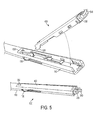
- FIGs. 3-4 illustrate a set of steps for assembling an embodiment of a temple chassis subassembly.
- spacer block 290 is placed onto temple chassis 120.
- spacer block 290 is welded onto temple chassis 120 along edges 310 and 320.
- hinge block 250 is placed onto temple chassis 120.
- hinge block 250 is welded onto temple chassis 120 along edges 330 and 340.
- FIG. 4 illustrates a second set of steps for assembling an embodiment of temple chassis subassembly 400.
- a backing (not shown) may be removed from tape 410 on both sides of reservoir 150. Reservoir 150 is placed against temple chassis 120.
- Compression arm 270 is then placed onto spacer block 290.
- Compression arm 270 is then welded onto spacer block 290.
- FIG. 5 illustrates a set of steps for assembling temple subassembly 500, according to an embodiment.
- tabs 520 of temple chassis subassembly 400 are slid into rear slot 530 of temple cover 110.
- temple chassis subassembly 400 is rotated within temple cover 110 until it snaps into place. It is recommended that slider subassembly 295 be positioned as far distally as possible within temple cover 110. Further, it is recommended that when snapping temple chassis subassembly 400 into temple cover 110, tube 540 does not become pinched between hinge block 250 and temple cover 110 or temple chassis subassembly 400.
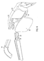
- FIGs. 6-7 illustrate a set of steps for assembling a frame assembly, according to an embodiment.
- an adhesive such as glue
- spring 230 is placed against hinge block 250.
- frame 610 is then pulled over lens module 200 so that upper portion 620 and lower portion 630 of frame 610 are coupled with lens module 200.
- An adhesive such as glue
- lens module 200 may be added to frame 610 after assembly of frame assembly 600 is complete.
- FIG. 7 shows a second set of steps for assembling an embodiment of frame assembly 600.
- FIG. 7 shows the frame assembled with spring 230, showing the addition of cover 720 to seal off the hinge mechanism and prevent access of water or contaminants to connecting tube 540.
- the steps shown in FIGs. 6 and 7 may be repeated for the second temple subassembly.
- adequate time is allowed for any glue or adhesive to cure.
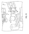
- FIG. 8 illustrates completed frame assembly 600 including temple chassis 120, frame 610 and lens module 200.
- FIG. 9 illustrates an embodiment of a spring that may be used in frame assembly 600.
- spring 910 includes an end 920. Additional embodiments of end 920 may include a cammed surface.
- end 920 rides up against a small peak 930. Force on end 920 from flexing creates stored energy that releases when temple arm 900 causes end 920 to move from peak 930.
- Temple arm 900 then accelerates and rotates to either folded or unfolded position.
- a hard stop 960 may be provided to prevent temple arm 900 from flexing too far.
- the connecting tube (not shown) is routed through the center of hinge 970 through gap 950.
- FIG. 10 shows another embodiment of a spring that may be used in frame assembly 600.
- spring 1010 is a sheet metal hinge that uses a folded sheet metal arm 1020 to provide spring force.
- End 1030 which is closest to lens module 200 is fixed within frame 610 (not shown).
- End 1040 is attached to temple arm 1050.
- the flexure of spring 1010 occurs primarily within the bend (i.e., folded sheet metal arm 1020).
- the connecting tube (not shown) is routed through the center of spring 1010 through gap 1060.
- spring 1010 is referred to herein as a "sheet metal" hinge, one of skill in the art will recognize that spring 1010 may be made of any material, even a non-metallic material, that satisfies the balance between flexibility and rigidity needed for spring 1010 to operate.
- FIG. 11 shows another embodiment of a hinge 1100.
- Hinge 1100 is configured to rotate around rotation axis A-A' with respect to a temple arm (not shown).
- cantilever tab 1110 engages with a corresponding ridge on the temple arm (not shown).
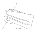
- FIG. 12 shows another embodiment of a hinge 1200.
- Hinge 1200 is configured to rotate around rotation axis B-B' with respect to a temple arm (not shown).
- cantilever tab 1210 engages with a corresponding ridge on the temple arm (not shown).
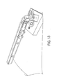
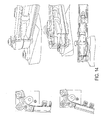
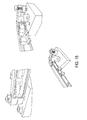
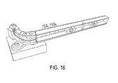
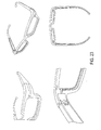
- FIGs. 13-16 show views of a leaf spring hinge from different perspectives, according to an embodiment of the present invention.
- FIG. 17 illustrates an exploded view of a leaf spring hinge above a breadboard, according to an embodiment of the present invention.
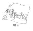
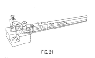
- FIGs. 18-21 show views of a sheet metal spring hinge from different perspectives, according to an embodiment of the present invention.
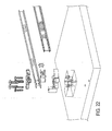
- FIG. 22 illustrates an exploded view of a sheet metal spring hinge above a breadboard, according to an embodiment of the present invention.
- FIG. 23 shows several views of an assembled embodiment of a pair of eyeglasses from different perspectives that includes a spring in accordance with an embodiment of the present invention.
- the pieces of the various actuator assemblies described herein may be manufactured through any suitable process, such as metal injection molding (MIM), cast, machining, plastic injection molding, and the like.
- MIM metal injection molding
- the choice of materials may be further informed by the requirements of, for example and without limitation, mechanical properties, temperature sensitivity, optical properties such as dispersion, moldability properties, or any other factor apparent to a person having ordinary skill in the art.
- the fluid used in the fluid lens may be a colorless fluid; however, other embodiments include fluid that is tinted, depending on the application, such as if the intended application is for sunglasses.
- fluid that may be used is manufactured by Dow Coming of Midland, MI, under the name “diffusion pump oil,” which is also generally referred to as "silicone oil.”
- the fluid lens may include a rigid optical lens made of glass, plastic, or any other suitable material.
- suitable materials include, for example and without limitation, Diethylglycol bisallyl carbonate (DEG-BAC), poly(methyl methacrylate), PMMA and a proprietary polyurea complex, trade name TRIVEX (PPG).
- the fluid lens may include a membrane made of a flexible, transparent, water impermeable material, such as, for example and without limitation, clear and elastic polyolefins, polycycloaliphatics, polyethers, polyesters, polyimides and polyurethanes, for example, polyvinylidene chloride films, including commercially available films, such as those manufactured as MYLAR or SARAN.
- a membrane made of a flexible, transparent, water impermeable material, such as, for example and without limitation, clear and elastic polyolefins, polycycloaliphatics, polyethers, polyesters, polyimides and polyurethanes, for example, polyvinylidene chloride films, including commercially available films, such as those manufactured as MYLAR or SARAN.
- Other polymers suitable for use as membrane materials include, for example and without limitation, polysulfones, polyurethanes, polythiourethanes, polyethylene terephthalate, polymers of cycloolefins and alipha
- the connecting tube may be made of one or more materials such as TYGON (polyvinyl chloride), PVDF (Polyvinyledene fluoride), and natural rubber.
- PVDF polyvinyl chloride
- PVDF Polyvinyledene fluoride
- natural rubber such as heat-shrunk flexible PVDF
- PVDF heat-shrunk flexible PVDF
- the temple cover may be any suitable shape, and may be made of plastic, metal, or any other suitable material.
- the temple cover is made of a lightweight material such as, for example and without limitation, high impact resistant plastics material, aluminum, titanium, or the like.
- the temple cover may be made entirely or partly of a transparent material.
- the reservoir may be made of Polyvinyledene Difluoride, such as Heat-shrink VITON®, supplied by DuPont Performance Elastomers LLC of Wilmington, DE, DERAY- KYF 190 manufactured by DSG-CANUSA of Meckenheim, Germany (flexible), RW-175 manufactured by Tyco Electronics Corp. of Berwyn, PA (formerly Raychem Corp.) (semirigid), or any other suitable material.
- Polyvinyledene Difluoride such as Heat-shrink VITON®, supplied by DuPont Performance Elastomers LLC of Wilmington, DE, DERAY- KYF 190 manufactured by DSG-CANUSA of Meckenheim, Germany (flexible), RW-175 manufactured by Tyco Electronics Corp. of Berwyn, PA (formerly Raychem Corp.) (semirigid), or any other suitable material.
- the screws used in the frame assembly may include, for example and without limitation, Visottica 07V120037017 shoulder screws produced by Visottica Industrie S.P.A. of Susegana, Italy. Other suitable types of screws or other attachment means, such as rivets, may be used.
Landscapes
- Physics & Mathematics (AREA)
- General Physics & Mathematics (AREA)
- Optics & Photonics (AREA)
- Health & Medical Sciences (AREA)
- Ophthalmology & Optometry (AREA)
- General Health & Medical Sciences (AREA)
- Eyeglasses (AREA)
- Pivots And Pivotal Connections (AREA)
- Prostheses (AREA)
Description
- Embodiments of the present invention relate to fluid-filled lenses and in particular to variable fluid-filled lenses.
- Basic fluid lenses have been known since about 1958, as described in
U.S. Pat. No. 2,836,101 . More recent examples may be found in "Dynamically Reconfigurable Fluid Core Fluid Cladding Lens in a Microfluidic Channel" by Tang et al, Lab Chip, 2008, vol. 8, p. 395, and in WIPO publicationWO2008/063442 . These applications of fluid lenses are directed towards photonics, digital phone and camera technology and microelectronics. - Fluid lenses have also been proposed for ophthalmic applications (see, e.g.,
U.S. Patent No. 7,085,065 ). In all cases, the advantages of fluid lenses, such as a wide dynamic range, ability to provide adaptive correction, robustness, and low cost have to be balanced against limitations in aperture size, possibility of leakage, and consistency in performance. The '065 patent, for example, has disclosed several improvements and embodiments directed towards effective containment of the fluid in the fluid lens to be used in ophthalmic applications, although not limited to them (see, e.g.,U.S. Patent No. 6,618,208 ). Power adjustment in fluid lenses has been effected by injecting additional fluid into a lens cavity, by electrowetting, application of ultrasonic impulse, and by utilizing swelling forces in a cross-linked polymer upon introduction of a swelling agent such as water. -
US 2,576,581 discloses polyfocal spectacles having a liquid expansible variable diopter lens in communication with a collapsible reservoir which is expanded or compressed through the action of a pressure plate adhesively secured to one side of the reservoir. - According to the invention, there is provided a hinge for a fluid-filled lens assembly as set out in
claim 1. - In an embodiment, the hinge for a fluid-filled lens assembly includes a base having a first end configured to connect to a temple arm of the lens assembly and a second end configured to connect to a frame of the lens assembly, wherein the base includes a gap that is shaped to allow for tubing to pass from the first end to the second end of the base.
- In an embodiment, the first end of the base includes a cammed surface configured to engage a surface of the temple arm.
- In an embodiment, the first and second ends of the base are configured to flex around a rotation axis of the hinge.
- In another embodiment, a fluid-filled lens assembly comprises: a temple arm; a reservoir disposed within the housing; a frame; a fluid-filled lens disposed within the frame; tubing connecting the reservoir to the fluid-filled lens; and a hinge attached to the temple arm and to the frame. The hinge includes a base having a gap that is shaped to allow for tubing to pass from a first end to a second end of the base.
- Further embodiments, features, and advantages of the present invention, as well as the structure and operation of the various embodiments of the present invention, are described in detail below with reference to the accompanying drawings.
- The accompanying drawings, which are incorporated herein and form a part of the specification, illustrate the present invention and, together with the description, further serve to explain the principles of the invention and to enable a person skilled in the pertinent art to make and use the invention.
-
FIG. 1 illustrates a perspective view of an embodiment of a caliper actuator assembly. -
FIG. 2 illustrates an exploded perspective view of an embodiment of a caliper actuator assembly. -
FIG. 3 illustrates a first set of steps for assembling an embodiment of a temple chassis subassembly. -
FIG. 4 illustrates a second set of steps for assembling an embodiment of a temple chassis subassembly. -
FIG. 5 illustrates a set of steps for assembling a temple subassembly, according to an embodiment. -
FIG. 6 illustrates a first set of steps for assembling a frame assembly, according to an embodiment. -
FIG. 7 illustrates a second set of steps for assembling a frame assembly, according to an embodiment. -
FIG. 8 illustrates a completed frame assembly, according to an embodiment. -
FIG. 9 illustrates a spring connected to a temple arm, according to an embodiment. -
FIG. 10 illustrates a spring connected to a temple arm, according to an embodiment. -
FIG. 11 shows a hinge, according to an embodiment. -
FIG. 12 shows a hinge, according to an embodiment. -
FIG. 13 shows a view of a leaf spring hinge embodiment. -
FIG. 14 shows further views of a leaf spring hinge embodiment. -
FIG. 15 shows further views of a leaf spring hinge embodiment. -
FIG. 16 shows a further view of a leaf spring hinge embodiment. -
FIG. 17 illustrates an exploded view of a leaf spring hinge embodiment. -
FIG. 18 shows a view of a sheet metal spring hinge, according to an embodiment. -
FIG. 19 shows further views of a sheet metal spring hinge, according to an embodiment. -
FIG. 20 shows further views of a sheet metal spring hinge, according to an embodiment. -
FIG. 21 shows a further view of a sheet metal spring hinge, according to an embodiment. -
FIG. 22 illustrates an exploded view of a sheet metal spring hinge embodiment. -
FIG. 23 shows multiple views of an assembled pair of eyeglasses, according to an embodiment. - Although specific configurations and arrangements are discussed, it should be understood that this is done for illustrative purposes only. A person skilled in the pertinent art will recognize that other configurations and arrangements can be used without departing from the scope of the claimed invention. It will be apparent to a person skilled in the pertinent art that this invention can also be employed in a variety of other applications.
- It is noted that references in the specification to "one embodiment," "an embodiment," "an example embodiment," etc., indicate that the embodiment described can include a particular feature, structure, or characteristic, but every embodiment may not necessarily include the particular feature, structure, or characteristic. Moreover, such phrases do not necessarily refer to the same embodiment. Further, when a particular feature, structure, or characteristic is described in connection with an embodiment, it would be within the knowledge of one skilled in the art to affect such feature, structure or characteristic in connection with other embodiments whether or not explicitly described.
- Fluid lenses have important advantages over conventional means of vision correction, such as rigid lenses and contact lenses. First, fluid lenses are easily adjustable. Thus an individual who requires an additional positive power correction to view near objects can be fitted with a fluid lens of base power matching the distance prescription. The user can then adjust the fluid lens to obtain additional positive power correction as needed to view objects at intermediate and other distances.
- Second, fluid lenses can be adjusted continuously over a desired power range by the wearer. As a result, the wearer can adjust the power to precisely match the refractive error for a particular object distance in a particular light environment. Thus, fluid lenses allow adjustment of power to compensate for alteration of the natural depth of focus of the eye that depends on the wearer's pupil size, which is in turn dependent on the ambient light level.
- Third, although 20/20 vision, which corresponds to an image resolution of 1 minute of arc (1/60 degree) is generally acknowledged to represent an acceptable quality of vision, the human retina is capable of finer image resolution. It is known that a healthy human retina is capable of resolving 20 seconds of arc (1/300 degree). Corrective eyeglasses designed to enable a patient to achieve this superior level of vision have a resolution of about 0.10D or better. This resolution can be achieved with continuously adjustable fluid lens elements.
- In an embodiment of a fluid filled lens in a pair of eyeglasses, the optical power of the fluid filled lens may be adjusted by moving an actuator attached to a reservoir located in a temple arm of the eyeglass frame. The reservoir is attached to the fluid filled lens via a connecting tube. Moving the actuator a first way compresses the reservoir and pushes fluid into the fluid lens. Moving the actuator a second way allows the reservoir to expand and pull fluid from the fluid lens. The compression and expansion of the reservoir changes the optical power of the fluid filled lens. In an embodiment, one or more fluid lenses may be provided, each with its own actuation system, so that a lens for each eye may be adjusted independently. This feature allow wearers, such as anisometropic patients, to correct any refractive error in each eye separately, so as to achieve appropriate correction in both eyes, which can result in better binocular vision and binocular summation. Further description and additional embodiments of the reservoir are described in
U.S. Appl. No. 12/904,736 . - In such fluid filled lens designs, the fluid must pass from the reservoir located in the temple arm of the eyeglasses through a hinge located at the juncture between the temple arm and the lens frame located on the front of the eyeglasses. Because the hinge is subject to repeated bending, the connecting tube may prematurely fail if made of a weak material. Further, if the connecting tube is bent beyond a certain level, the fluid pressure in the lens may be affected. Accordingly, a fluid filled lens assembly according to an embodiment of the present invention provides ample space within the temple and end piece for the connecting tube to bend without kinking. In addition, according to an embodiment, the entire hinge mechanism may be located within the volume of the temple arm and frame.
-
FIG. 1 illustrates a perspective view of acaliper actuator assembly 100, according to an embodiment of the present invention.Caliper actuator assembly 100 includestemple cover 110, which includes a hollow outer portion and a hollow inner portion formed together to enclose additional pieces ofcaliper actuator assembly 100.Distal end 160 oftemple cover 110 is shaped to fit over a wearer's ear.Caliper actuator assembly 100 further includestemple chassis 120,wheel 130, andslider 140. In an embodiment,wheel 130 andslider 140 are longitudinally slidably disposed withintemple chassis 120.Caliper actuator assembly 100 operates to compressreservoir 150 and transfer fluid betweenreservoir 150 and a fluid lens (not shown). The compressing force may be applied in various ways, such as for example, by rotatingwheel 130 or by translating the wheel along a slot. Additional methods of applying compressing force are also described herein. The compression ofreservoir 150 may be effected either by compressingreservoir 150 in a vertical or horizontal direction against a ceiling or inner wall oftemple chassis 120, as described in detail below. -
FIG. 2 illustrates an exploded perspective view of an embodiment ofcaliper actuator assembly 100. In an embodiment, slider subassembly 295 (described below with respect toFIGs. 3-4 ) is configured to translate along one or more oftemple cover 110 andtemple chassis 120 in order to compressreservoir 150. In operation, a user rotateswheel 130, which movesslider block 255, which in turn compresses a relatively stiff metal plate, such ascompression arm 270, that is in contact with afirst side surface 265 ofreservoir 150. A second side surface (not shown) ofreservoir 150 is placed againstinner wall 285 oftemple chassis 120, a portion oftemple cover 110, or any other suitable surface.Slider 140 presses againstcompression arm 270, which compressesreservoir 150 in a controllable manner. In an embodiment, the length of the lateral movement ofwheel 130 is proportional to the magnitude of compression of the compression arm, and is proportional to the magnitude of compression of the reservoir. Further description and additional embodiments of the actuator are described inU.S. Appl. No. 12/904,720 . - In an embodiment,
wheel 130 has a knurled edge in order to provide secure contact with the finger of the user as well more precise control over the translation ofwheel 130. -
Lens module 200 is connected viaoutlet port 245 to a connecting tube (not shown), which is connected toreservoir 150.Lens module 200 may further include a flexible back surface provided by, for example, a flexible membrane (not shown) stretched flat over the edge of rigid optical lens. To change the optical power of fluid filledlens module 200, the membrane may be inflated through the addition of a fluid in communication withreservoir 150. - The connecting tube delivers fluid from
lens module 200 toreservoir 150 and vice versa. The connecting tube is designed to be relatively impermeable to the fluid contained therein. In an embodiment, the connecting tube is configured to allow a minimum flow rate at all times in order to ensure a minimum speed of response to theuser moving wheel 130 in order to change the optical power of fluid filledlens module 200. The connecting tube is connected at one end tooutlet port 245 oflens module 200 and at the other end toreservoir 150. In an embodiment, the overall assembly including thelens module 200, the connecting tube, andreservoir 150 is designed to maintain a seal excluding fluids and air for an overall use period of two years or more. In an embodiment, the connecting tube has to be thin in order to be accommodated within the hinge cavity. In an embodiment, it is less than 2.0 mm in outer diameter and less than 0.50 mm in wall thickness, in order to maintain an adequate flow of fluid. In an embodiment, it is capable of being bent by an angle of no less than 60 degrees. In an embodiment, it is capable of being bent by an angle of no less than 45 degrees without crimping. In an embodiment, it is durable to repeated flexing of the hinge. -
Hinge block 250 andspring 230 are enclosed within a covered area betweeninner block 210 andouter block 240.Hinge block 250 includes a gap that is shaped to allow the connecting tube to pass throughhinge block 250. Additional embodiments of the spring are described below with respect toFIGs. 9-22 .Caliper actuator assembly 100 includeswheel 130 held in place byaxle 280,slider 140,slider block 255,spacer block 290, andcompression arm 270. These parts are assembled into a temple chassis subassembly and are held in place byscrews 235.Rubber strip 205 includes a flexible surface upon which wheel 130 may move. In an embodiment,wheel 130 may rotate. In other embodiments it may translate, and in other embodiments it may rotate and translate. -
FIGs. 3-4 illustrate a set of steps for assembling an embodiment of a temple chassis subassembly. Beginning withFIG. 3 ,spacer block 290 is placed ontotemple chassis 120. Next,spacer block 290 is welded ontotemple chassis 120 alongedges hinge block 250 is placed ontotemple chassis 120. Next,hinge block 250 is welded ontotemple chassis 120 alongedges FIG. 4 , which illustrates a second set of steps for assembling an embodiment oftemple chassis subassembly 400. A backing (not shown) may be removed fromtape 410 on both sides ofreservoir 150.Reservoir 150 is placed againsttemple chassis 120.Compression arm 270 is then placed ontospacer block 290.Compression arm 270 is then welded ontospacer block 290. -
FIG. 5 illustrates a set of steps for assemblingtemple subassembly 500, according to an embodiment. First,tabs 520 oftemple chassis subassembly 400 are slid intorear slot 530 oftemple cover 110. Next,temple chassis subassembly 400 is rotated withintemple cover 110 until it snaps into place. It is recommended thatslider subassembly 295 be positioned as far distally as possible withintemple cover 110. Further, it is recommended that when snappingtemple chassis subassembly 400 intotemple cover 110,tube 540 does not become pinched betweenhinge block 250 andtemple cover 110 ortemple chassis subassembly 400. -
FIGs. 6-7 illustrate a set of steps for assembling a frame assembly, according to an embodiment. Beginning withFIG. 6 , in an embodiment, an adhesive, such as glue, is applied to the inside edge offrame 610. Next,spring 230 is placed againsthinge block 250. In an embodiment,frame 610 is then pulled overlens module 200 so thatupper portion 620 andlower portion 630 offrame 610 are coupled withlens module 200. An adhesive, such as glue, may be used tobond lens module 200 to frame 610. One of skill in the art will recognize that, in another embodiment,lens module 200 may be added toframe 610 after assembly offrame assembly 600 is complete. The frame assembly continues withFIG. 7 , which shows a second set of steps for assembling an embodiment offrame assembly 600. In an embodiment, screws 235 are inserted into respective screw holes 710 inframe 610 intohinge block 250.FIG. 7 shows the frame assembled withspring 230, showing the addition ofcover 720 to seal off the hinge mechanism and prevent access of water or contaminants to connectingtube 540. The steps shown inFIGs. 6 and7 may be repeated for the second temple subassembly. In an embodiment, afterframe assembly 600 is assembled, adequate time is allowed for any glue or adhesive to cure. -
FIG. 8 illustrates completedframe assembly 600 includingtemple chassis 120,frame 610 andlens module 200. - Additional embodiments of hinge springs will now be described.
FIG. 9 illustrates an embodiment of a spring that may be used inframe assembly 600. In an embodiment,spring 910 includes anend 920. Additional embodiments ofend 920 may include a cammed surface. Whentemple arm 900 rotates, end 920 rides up against asmall peak 930. Force onend 920 from flexing creates stored energy that releases whentemple arm 900 causes end 920 to move frompeak 930.Temple arm 900 then accelerates and rotates to either folded or unfolded position. Ahard stop 960 may be provided to preventtemple arm 900 from flexing too far. During assembly, the connecting tube (not shown) is routed through the center ofhinge 970 throughgap 950. -
FIG. 10 shows another embodiment of a spring that may be used inframe assembly 600. In an embodiment,spring 1010 is a sheet metal hinge that uses a foldedsheet metal arm 1020 to provide spring force.End 1030, which is closest tolens module 200 is fixed within frame 610 (not shown).End 1040 is attached totemple arm 1050. The flexure ofspring 1010 occurs primarily within the bend (i.e., folded sheet metal arm 1020). During assembly, the connecting tube (not shown) is routed through the center ofspring 1010 throughgap 1060. Althoughspring 1010 is referred to herein as a "sheet metal" hinge, one of skill in the art will recognize thatspring 1010 may be made of any material, even a non-metallic material, that satisfies the balance between flexibility and rigidity needed forspring 1010 to operate. -
FIG. 11 shows another embodiment of ahinge 1100.Hinge 1100 is configured to rotate around rotation axis A-A' with respect to a temple arm (not shown). Ashinge 1100 rotates around rotation axis A-A', cantilever tab 1110 engages with a corresponding ridge on the temple arm (not shown). -
FIG. 12 shows another embodiment of ahinge 1200.Hinge 1200 is configured to rotate around rotation axis B-B' with respect to a temple arm (not shown). Ashinge 1200 rotates around rotation axis B-B', cantilever tab 1210 engages with a corresponding ridge on the temple arm (not shown). -
FIGs. 13-16 show views of a leaf spring hinge from different perspectives, according to an embodiment of the present invention. -
FIG. 17 illustrates an exploded view of a leaf spring hinge above a breadboard, according to an embodiment of the present invention. -
FIGs. 18-21 show views of a sheet metal spring hinge from different perspectives, according to an embodiment of the present invention. -
FIG. 22 illustrates an exploded view of a sheet metal spring hinge above a breadboard, according to an embodiment of the present invention. -
FIG. 23 shows several views of an assembled embodiment of a pair of eyeglasses from different perspectives that includes a spring in accordance with an embodiment of the present invention. - The pieces of the various actuator assemblies described herein, for example, but not limited to, the temple cover, temple chassis, wheel, slider, spring, screws, inner block, outer block, axle, compression arm, spacer block, etc, may be manufactured through any suitable process, such as metal injection molding (MIM), cast, machining, plastic injection molding, and the like. The choice of materials may be further informed by the requirements of, for example and without limitation, mechanical properties, temperature sensitivity, optical properties such as dispersion, moldability properties, or any other factor apparent to a person having ordinary skill in the art.
- The fluid used in the fluid lens may be a colorless fluid; however, other embodiments include fluid that is tinted, depending on the application, such as if the intended application is for sunglasses. One example of fluid that may be used is manufactured by Dow Coming of Midland, MI, under the name "diffusion pump oil," which is also generally referred to as "silicone oil."
- The fluid lens may include a rigid optical lens made of glass, plastic, or any other suitable material. Other suitable materials include, for example and without limitation, Diethylglycol bisallyl carbonate (DEG-BAC), poly(methyl methacrylate), PMMA and a proprietary polyurea complex, trade name TRIVEX (PPG).
- The fluid lens may include a membrane made of a flexible, transparent, water impermeable material, such as, for example and without limitation, clear and elastic polyolefins, polycycloaliphatics, polyethers, polyesters, polyimides and polyurethanes, for example, polyvinylidene chloride films, including commercially available films, such as those manufactured as MYLAR or SARAN. Other polymers suitable for use as membrane materials include, for example and without limitation, polysulfones, polyurethanes, polythiourethanes, polyethylene terephthalate, polymers of cycloolefins and aliphatic or alicyclic polyethers.
- The connecting tube may be made of one or more materials such as TYGON (polyvinyl chloride), PVDF (Polyvinyledene fluoride), and natural rubber. For example, PVDF (such as heat-shrunk flexible PVDF) may be suitable based on its durability, permeability, and resistance to crimping. In addition
- The temple cover may be any suitable shape, and may be made of plastic, metal, or any other suitable material. In an embodiment, the temple cover is made of a lightweight material such as, for example and without limitation, high impact resistant plastics material, aluminum, titanium, or the like. In an embodiment, the temple cover may be made entirely or partly of a transparent material.
- The reservoir may be made of Polyvinyledene Difluoride, such as Heat-shrink VITON®, supplied by DuPont Performance Elastomers LLC of Wilmington, DE, DERAY- KYF 190 manufactured by DSG-CANUSA of Meckenheim, Germany (flexible), RW-175 manufactured by Tyco Electronics Corp. of Berwyn, PA (formerly Raychem Corp.) (semirigid), or any other suitable material.
- The screws used in the frame assembly may include, for example and without limitation, Visottica 07V120037017 shoulder screws produced by Visottica Industrie S.P.A. of Susegana, Italy. Other suitable types of screws or other attachment means, such as rivets, may be used.
- Although various embodiments of the present invention have been described above, it should be understood that they have been presented by way of example only, and not limitation. It will be apparent to persons skilled in the relevant art that various changes in form and detail can be made therein without departing from the scope of the claimed invention.
Claims (15)
- A hinge (910, 1010, 1100, 1200) for a fluid-filled lens assembly, the hinge comprising:a base (230, 250) having a first end (920, 1040) for connecting to a temple arm (900, 1050) of the lens assembly and a second end (1030) for connecting to a frame of the lens assembly,characterised in that:the base includes a gap (950, 1060) that is shaped to allow a tube for passing fluid to pass from the first end to the second end of the base, andwherein the first and second ends of the base are capable of flexing around a rotation axis of the hinge between an open position in which the temple arm is substantially perpendicular to the frame and a closed position in which the temple arm is substantially parallel to the frame.
- The hinge of claim 1, wherein the gap has a size that allows the tube to bend without kinking when the temple arm is rotated between the open position and the closed position,
wherein the base includes a peaked surface (930) capable of engaging a rounded surface of the temple arm when the temple arm is rotated a first predetermined distance to create spring energy in the hinge that resists further rotation of the temple arm, and
wherein the peaked surface is capable of releasing the spring energy in the hinge to accelerate the temple arm when the temple arm is rotated a second predetermined distance beyond the first predetermined distance. - The hinge of claim 2, further comprising a hard stop (960) to prevent rotation beyond a point.
- The hinge of claim 2, wherein the fluid-filled lens assembly is an eyeglass assembly.
- The hinge of claim 4, wherein the eyeglass assembly includes a temple arm (900, 1050), and wherein the hinge is disposed at least partially within the temple arm.
- The hinge of claim 1, wherein the base includes a U-shaped bend to facilitate bending around the rotation axis of the hinge.
- The hinge of claim 1, wherein the hinge further comprises a hard stop to prevent rotation beyond a point.
- The hinge of claim 1, wherein the wherein the gap provides space to allow the tube to bend without kinking when the temple arm is rotated between an open position in which the temple arm is substantially perpendicular to the frame and a closed position in which the temple arm is substantially parallel to the frame.
- The hinge of claim 1, wherein the fluid-filled lens assembly is an eyeglass assembly.
- A fluid-filled lens assembly comprising:a temple arm;a reservoir (150) disposed within a housing;a frame (610);a fluid-filled lens (200) disposed within the frame;a tube for passing fluid connecting the reservoir to the fluid-filled lens; anda hinge according to claim 1.
- The fluid-filled lens assembly of claim 10, wherein the base of the hinge includes a U-shaped bend to facilitate bending around the rotation axis of the hinge.
- The fluid-filled lens assembly of claim 10, wherein the hinge further comprises a hard stop to prevent rotation beyond a point.
- The fluid-filled lens assembly of claim 12, wherein the hinge is disposed at least partially within the temple arm.
- The fluid-filled lens assembly of claim 10, wherein the fluid-filled lens assembly is an eyeglass assembly.
- The fluid-filled lens assembly of claim 14, wherein the hinge is disposed at least partially within the temple arm.
Priority Applications (1)
| Application Number | Priority Date | Filing Date | Title |
|---|---|---|---|
| PL10824198T PL2488900T3 (en) | 2009-10-15 | 2010-10-15 | Hinge mechanism for a fluid filled lens assembly |
Applications Claiming Priority (3)
| Application Number | Priority Date | Filing Date | Title |
|---|---|---|---|
| US25181909P | 2009-10-15 | 2009-10-15 | |
| US12/904,769 US8353593B2 (en) | 2009-10-15 | 2010-10-14 | Hinge mechanism for a fluid filled lens assembly |
| PCT/US2010/052910 WO2011047311A1 (en) | 2009-10-15 | 2010-10-15 | Hinge mechanism for a fluid filled lens assembly |
Publications (3)
| Publication Number | Publication Date |
|---|---|
| EP2488900A1 EP2488900A1 (en) | 2012-08-22 |
| EP2488900A4 EP2488900A4 (en) | 2013-03-06 |
| EP2488900B1 true EP2488900B1 (en) | 2014-03-19 |
Family
ID=43876597
Family Applications (1)
| Application Number | Title | Priority Date | Filing Date |
|---|---|---|---|
| EP10824198.5A Not-in-force EP2488900B1 (en) | 2009-10-15 | 2010-10-15 | Hinge mechanism for a fluid filled lens assembly |
Country Status (19)
| Country | Link |
|---|---|
| US (4) | US8353593B2 (en) |
| EP (1) | EP2488900B1 (en) |
| JP (1) | JP5677444B2 (en) |
| KR (4) | KR20180033306A (en) |
| CN (2) | CN104503104B (en) |
| AR (1) | AR078655A1 (en) |
| AU (1) | AU2010306638B2 (en) |
| BR (1) | BR112012008864A2 (en) |
| CA (1) | CA2777732C (en) |
| DK (1) | DK2488900T3 (en) |
| ES (1) | ES2469100T3 (en) |
| HK (1) | HK1175541A1 (en) |
| IL (3) | IL219199A (en) |
| MX (1) | MX2012004394A (en) |
| PL (1) | PL2488900T3 (en) |
| PT (1) | PT2488900E (en) |
| RU (1) | RU2611286C2 (en) |
| WO (1) | WO2011047311A1 (en) |
| ZA (1) | ZA201202885B (en) |
Families Citing this family (16)
| Publication number | Priority date | Publication date | Assignee | Title |
|---|---|---|---|---|
| US8817381B2 (en) | 2009-10-13 | 2014-08-26 | Adlens Beacon, Inc. | Full field membrane design for non-round liquid lens assemblies |
| US8136942B2 (en) | 2009-10-14 | 2012-03-20 | Adlens Beacon, Inc. | Aspheric fluid filled lens optic |
| BR112012008839A2 (en) | 2009-10-15 | 2020-06-23 | Adlens Beacon, Inc. | "DRIVES FOR A SEALED FLUID-FILLED LENS AND FOR A FLUID-FILLED LENS" |
| US8353593B2 (en) * | 2009-10-15 | 2013-01-15 | Adlens Beacon, Inc. | Hinge mechanism for a fluid filled lens assembly |
| US8894200B2 (en) | 2010-06-30 | 2014-11-25 | Addo Industries, Llc | Innovative and aesthetic alternative to traditional spectacle correction |
| GB201205394D0 (en) * | 2012-03-27 | 2012-05-09 | Adlens Ltd | Improvements in or relating to deformable non-round membrane assemblies |
| US9535264B2 (en) | 2012-07-13 | 2017-01-03 | Adlens Beacon, Inc. | Fluid lenses, lens blanks, and methods of manufacturing the same |
| US10261338B2 (en) | 2015-01-15 | 2019-04-16 | Addo Industries, Llc | Eyewear comprising suspension system for nose and ears |
| CN105911721A (en) * | 2016-06-08 | 2016-08-31 | 丽水市飞天人机械设计有限公司 | Intelligent glasses capable of freely adjusting degree |
| US10852562B2 (en) * | 2017-10-31 | 2020-12-01 | Snap Inc. | Conductive connection through eyewear hinge |
| CN110068939B (en) | 2018-01-22 | 2021-11-26 | 京东方科技集团股份有限公司 | Glasses |
| WO2019156129A1 (en) | 2018-02-07 | 2019-08-15 | 三井化学株式会社 | Eyewear |
| CN111936916B (en) * | 2018-03-23 | 2022-05-17 | 斯纳普公司 | Hinge assembly of glasses device |
| RU2718128C1 (en) * | 2019-09-06 | 2020-03-30 | Общество с ограниченной ответственностью "Алан-Абрис" | Connecting loop-lock for eyeglass frames and temples |
| US20220099998A1 (en) * | 2020-09-25 | 2022-03-31 | Shih-Yun Huang | Eyewear hinge device |
| US11856986B2 (en) | 2020-10-19 | 2024-01-02 | Rai Strategic Holdings, Inc. | Customizable panel for aerosol delivery device |
Family Cites Families (91)
| Publication number | Priority date | Publication date | Assignee | Title |
|---|---|---|---|---|
| US2576581A (en) | 1946-07-09 | 1951-11-27 | Benjamin F Edwards | Polyfocal spectacles |
| US2836101A (en) | 1955-09-01 | 1958-05-27 | Swart Dev Company De | Optical elements |
| IT560271A (en) | 1956-10-08 | |||
| GB1209234A (en) | 1968-03-11 | 1970-10-21 | Nat Res Dev | Improvements in or relating to variable focus lenses |
| US3614215A (en) | 1970-04-23 | 1971-10-19 | Leo Mackta | Fluid bifocal spectacle |
| US4181408A (en) | 1977-12-05 | 1980-01-01 | Senders John W | Vision compensation |
| JPS57180316U (en) * | 1981-05-09 | 1982-11-16 | ||
| US4477158A (en) | 1981-10-15 | 1984-10-16 | Pollock Stephen C | Lens system for variable refraction |
| JPS5956070A (en) * | 1982-09-20 | 1984-03-31 | 株式会社東芝 | Pivotal supporter for door of storehouse |
| GB2183059B (en) | 1985-11-05 | 1989-09-27 | Michel Treisman | Suspension system for a flexible optical membrane |
| IL83179A0 (en) | 1987-07-14 | 1987-12-31 | Daniel Barnea | Variable lens |
| FR2651584B1 (en) | 1989-09-07 | 1992-11-13 | Essilor Int | EYEWEAR MOUNT BRANCH WITH INTERCHANGEABLE BRANCH BODY. |
| US5138494A (en) | 1990-05-07 | 1992-08-11 | Stephen Kurtin | Variable focal length lens |
| US5440357A (en) | 1991-09-03 | 1995-08-08 | Lawrence D. Quaglia | Vari-lens phoropter and automatic fast focusing infinitely variable focal power lens units precisely matched to varying distances by radar and electronics |
| US5229885A (en) | 1991-09-03 | 1993-07-20 | Quaglia Lawrence D | Infinitely variable focal power lens units precisely matched to varying distances by radar and electronics |
| US5182585A (en) | 1991-09-26 | 1993-01-26 | The Arizona Carbon Foil Company, Inc. | Eyeglasses with controllable refracting power |
| JPH0655122U (en) * | 1992-12-28 | 1994-07-26 | 株式会社敷島 | Eyeglass frames |
| US5371629A (en) | 1993-02-04 | 1994-12-06 | Kurtin; Stephen | Non-circular variable focus lens |
| US5739959A (en) | 1993-07-20 | 1998-04-14 | Lawrence D. Quaglia | Automatic fast focusing infinitely variable focal power lens units for eyeglasses and other optical instruments controlled by radar and electronics |
| JPH0749404A (en) | 1993-08-05 | 1995-02-21 | Nippondenso Co Ltd | Lens with variable focal point |
| AU7788394A (en) | 1993-10-04 | 1995-05-01 | William Andrew Hallett | Improvements in and relating to target material detection |
| US5668620A (en) | 1994-04-12 | 1997-09-16 | Kurtin; Stephen | Variable focal length lenses which have an arbitrarily shaped periphery |
| US5900921A (en) | 1994-07-06 | 1999-05-04 | Jong-Deok Park | Lens for diplopia and amblyopia and glasses using the same |
| US5515203A (en) | 1994-07-08 | 1996-05-07 | Nye; William S. | Educational lens |
| US5999328A (en) | 1994-11-08 | 1999-12-07 | Kurtin; Stephen | Liquid-filled variable focus lens with band actuator |
| US5636368A (en) | 1994-12-23 | 1997-06-03 | Xilinx, Inc. | Method for programming complex PLD having more than one function block type |
| US5563528A (en) | 1995-05-02 | 1996-10-08 | Xilinx, Inc. | Multiplexer for programmable logic device |
| US5774274A (en) | 1995-05-12 | 1998-06-30 | Schachar; Ronald A. | Variable focus lens by small changes of the equatorial lens diameter |
| GB9511091D0 (en) | 1995-06-01 | 1995-07-26 | Silver Joshua D | Variable power spectacles |
| US5684637A (en) | 1995-07-19 | 1997-11-04 | Floyd; Johnnie E. | Fluid filled and pressurized lens with flexible optical boundary having variable focal length |
| FR2746151B1 (en) | 1996-03-15 | 1998-05-22 | DEVICE FOR THE PROTECTION AND GUIDE OF AN ASSOCIATED ELONGATED COMPONENT, AT THE JOINT, WITH TWO RIGID ELEMENTS JOINTED ONE TO THE OTHER, AND THEIR INDUSTRIAL APPLICATIONS | |
| US5774273A (en) | 1996-08-23 | 1998-06-30 | Vari-Lite, Inc. | Variable-geometry liquid-filled lens apparatus and method for controlling the energy distribution of a light beam |
| HUP0000443A3 (en) | 1996-09-13 | 2002-11-28 | Silver Joshua David Oxford | Variable focus lens and method for the production thereof |
| US5790882A (en) | 1996-11-13 | 1998-08-04 | Xilinx, Inc. | Programmable logic device placement method utilizing weighting function to facilitate pin locking |
| US6091892A (en) | 1996-11-13 | 2000-07-18 | Xilinx, Inc. | Method for mapping product terms in a complex programmable logic device |
| US6626532B1 (en) | 1997-06-10 | 2003-09-30 | Olympus Optical Co., Ltd. | Vari-focal spectacles |
| US5952846A (en) | 1997-08-08 | 1999-09-14 | Xilinx, Inc. | Method for reducing switching noise in a programmable logic device |
| GB9805977D0 (en) | 1998-03-19 | 1998-05-20 | Silver Joshua D | Improvements in variable focus optical devices |
| US5973852A (en) | 1998-03-26 | 1999-10-26 | The United States Of America As Represented By The Secretary Of The Air Force | Variable power fluid lens |
| US6552860B1 (en) | 1998-05-01 | 2003-04-22 | Ray M. Alden | Variable Fresnel type structures and process |
| US5956183A (en) | 1998-05-26 | 1999-09-21 | Epstein; Saul | Field-customizable variable focal length lens |
| US6040947A (en) | 1998-06-09 | 2000-03-21 | Lane Research | Variable spectacle lens |
| IT1306702B1 (en) * | 1999-04-15 | 2001-10-02 | Visottica Spa | ELASTIC HINGE FOR GLASSES WITH SAFETY LOCK. |
| US6619799B1 (en) | 1999-07-02 | 2003-09-16 | E-Vision, Llc | Optical lens system with electro-active lens having alterably different focal lengths |
| US7604349B2 (en) | 1999-07-02 | 2009-10-20 | E-Vision, Llc | Static progressive surface region in optical communication with a dynamic optic |
| US6053610A (en) | 1999-07-15 | 2000-04-25 | Lane Research | Actuation mechanism for variable focal length spectacles |
| US7646544B2 (en) | 2005-05-14 | 2010-01-12 | Batchko Robert G | Fluidic optical devices |
| GB0100031D0 (en) | 2001-01-02 | 2001-02-14 | Silver Joshua D | Variable focus optical apparatus |
| US6715876B2 (en) | 2001-11-19 | 2004-04-06 | Johnnie E. Floyd | Lens arrangement with fluid cell and prescriptive element |
| CN100462844C (en) | 2002-08-23 | 2009-02-18 | 株式会社尼康 | Projection optical system and method for photolithography and exposure apparatus and method using same |
| IL151592A (en) | 2002-09-04 | 2008-06-05 | Josef Bekerman | Variable optical power spectacles for eyesight rehabilitation and methods for lens optical power control |
| US6836374B2 (en) | 2002-11-20 | 2004-12-28 | Powervision, Inc. | Lens system and methods for power adjustment |
| CN1216083C (en) | 2003-04-15 | 2005-08-24 | 河北工业大学 | Binuclear beta-diketone catalyst for synthesizing syndiotactic polystyrene and its preparation method |
| CN101825762A (en) | 2003-10-23 | 2010-09-08 | 安德里斯·奥布雷斯基 | Imaging optical system |
| CN2682432Y (en) * | 2003-11-25 | 2005-03-02 | 黄水财 | Lens with continuously adjustable focal length |
| US6992843B2 (en) | 2003-12-16 | 2006-01-31 | Metastable Instruments, Inc. | Precision optical wedge light beam scanner |
| US7453646B2 (en) | 2004-03-31 | 2008-11-18 | The Regents Of The University Of California | Fluidic adaptive lens systems and methods |
| EP1735644A4 (en) | 2004-03-31 | 2010-01-27 | Univ California | Fluidic adaptive lens |
| US7359124B1 (en) | 2004-04-30 | 2008-04-15 | Louisiana Tech University Research Foundation As A Division Of The Louisiana Tech University Foundation | Wide-angle variable focal length lens system |
| JP4897680B2 (en) | 2004-07-20 | 2012-03-14 | エージェンシー フォー サイエンス, テクノロジー アンド リサーチ | Variable focus micro lens |
| US7261736B1 (en) | 2004-07-21 | 2007-08-28 | Massachusetts Eye & Ear Infirmary | Vision prosthesis with artificial muscle actuator |
| US20060066808A1 (en) | 2004-09-27 | 2006-03-30 | Blum Ronald D | Ophthalmic lenses incorporating a diffractive element |
| US7826145B2 (en) | 2004-11-05 | 2010-11-02 | The Regents Of The University Of California | Fluidic adaptive lens systems with pumping systems |
| JP2006195336A (en) * | 2005-01-17 | 2006-07-27 | Mitani Optical Kk | Spring hinge spectacles |
| US7142369B2 (en) | 2005-01-21 | 2006-11-28 | Research Foundation Of The University Of Central Florida, Inc. | Variable focus liquid lens |
| US7338159B2 (en) | 2005-03-21 | 2008-03-04 | Brett Spivey | Adjustable focus lenses |
| US7325922B2 (en) | 2005-03-21 | 2008-02-05 | Quexta, Inc | Adjustable focus eyeglasses |
| US20060245071A1 (en) | 2005-04-29 | 2006-11-02 | Agilent Technologies | Lens correction element, system and method |
| US7697214B2 (en) | 2005-05-14 | 2010-04-13 | Holochip Corporation | Fluidic lens with manually-adjustable focus |
| CA2609194A1 (en) * | 2005-05-20 | 2006-11-23 | Foto Ottica Cescon Di Cescon Stefano | Spherical joint |
| JP2006343506A (en) | 2005-06-08 | 2006-12-21 | Sony Corp | Lens driving device and imaging apparatus |
| GB2427484A (en) | 2005-06-21 | 2006-12-27 | Global Bionic Optics Pty Ltd | Variable power fluid lens with flexible wall |
| GB0613688D0 (en) * | 2006-07-10 | 2006-08-16 | Silver Joshua D | Variable focus lens and spectacles |
| BRPI0618010A2 (en) | 2005-10-28 | 2011-08-16 | J & J Technologies Ltd | variable focus lens |
| JP2009518676A (en) | 2005-12-12 | 2009-05-07 | コーニンクレッカ フィリップス エレクトロニクス エヌ ヴィ | Prevention of solution flow in a fluid focus lens. |
| US7382544B2 (en) | 2006-02-10 | 2008-06-03 | Honeywell International Inc. | Devices and related methods for light distribution |
| KR20070120872A (en) * | 2006-07-26 | 2007-12-26 | 트렌스프레임 리미티드 라이어빌러티 컴퍼니 | Improvement for eye glass frame adapted for the removal and insertion of lenses |
| US7256943B1 (en) | 2006-08-24 | 2007-08-14 | Teledyne Licensing, Llc | Variable focus liquid-filled lens using polyphenyl ethers |
| US7866816B2 (en) | 2006-10-10 | 2011-01-11 | Lane Research, Llc | Variable focus spectacles |
| GB0621065D0 (en) | 2006-10-23 | 2006-11-29 | Silver Joshua D | Variable focus lens and spectacles |
| US7324287B1 (en) | 2006-11-07 | 2008-01-29 | Corning Incorporated | Multi-fluid lenses and optical devices incorporating the same |
| KR20080043106A (en) | 2006-11-13 | 2008-05-16 | 삼성전자주식회사 | Optical lens and manufacturing method thereof |
| US20080117521A1 (en) | 2006-11-17 | 2008-05-22 | Lucent Technologies Inc. | Liquid lenses with cycloalkanes |
| US7369321B1 (en) | 2007-01-16 | 2008-05-06 | University Of Central Florida Research Foundation, Inc. | Variable-focus liquid lens |
| JP3135210U (en) * | 2007-06-26 | 2007-09-06 | 浜本テクニカル株式会社 | Spring hinged glasses frame |
| US20090195882A1 (en) | 2008-02-05 | 2009-08-06 | Bolle Cristian A | Mechanical lenses |
| JP4544331B2 (en) | 2008-04-04 | 2010-09-15 | ソニー株式会社 | Conversion lens device and imaging device |
| US20100208194A1 (en) | 2009-02-13 | 2010-08-19 | Amitava Gupta | Variable focus liquid filled lens apparatus |
| US8087778B2 (en) | 2009-02-13 | 2012-01-03 | Adlens Beacon, Inc. | Variable focus liquid filled lens mechanism |
| US8353593B2 (en) | 2009-10-15 | 2013-01-15 | Adlens Beacon, Inc. | Hinge mechanism for a fluid filled lens assembly |
| US8596781B2 (en) * | 2009-10-15 | 2013-12-03 | Adlens Beacon, Inc. | Fluid filled lens reservoir system and manufacturing method of the reservoir system |
-
2010
- 2010-10-14 US US12/904,769 patent/US8353593B2/en not_active Expired - Fee Related
- 2010-10-15 EP EP10824198.5A patent/EP2488900B1/en not_active Not-in-force
- 2010-10-15 AR ARP100103779A patent/AR078655A1/en unknown
- 2010-10-15 KR KR1020187008263A patent/KR20180033306A/en not_active Application Discontinuation
- 2010-10-15 KR KR1020127012329A patent/KR101644672B1/en active IP Right Grant
- 2010-10-15 WO PCT/US2010/052910 patent/WO2011047311A1/en active Application Filing
- 2010-10-15 KR KR1020167020192A patent/KR102034181B1/en active IP Right Grant
- 2010-10-15 CA CA2777732A patent/CA2777732C/en not_active Expired - Fee Related
- 2010-10-15 CN CN201410723001.9A patent/CN104503104B/en not_active Expired - Fee Related
- 2010-10-15 RU RU2012119616A patent/RU2611286C2/en not_active IP Right Cessation
- 2010-10-15 PL PL10824198T patent/PL2488900T3/en unknown
- 2010-10-15 JP JP2012534408A patent/JP5677444B2/en not_active Expired - Fee Related
- 2010-10-15 MX MX2012004394A patent/MX2012004394A/en active IP Right Grant
- 2010-10-15 PT PT108241985T patent/PT2488900E/en unknown
- 2010-10-15 ES ES10824198.5T patent/ES2469100T3/en active Active
- 2010-10-15 BR BR112012008864-5A patent/BR112012008864A2/en not_active Application Discontinuation
- 2010-10-15 AU AU2010306638A patent/AU2010306638B2/en not_active Ceased
- 2010-10-15 KR KR1020197030103A patent/KR102086015B1/en active IP Right Grant
- 2010-10-15 CN CN201080057469.9A patent/CN102667537B/en not_active Expired - Fee Related
- 2010-10-15 DK DK10824198.5T patent/DK2488900T3/en active
-
2012
- 2012-04-15 IL IL219199A patent/IL219199A/en not_active IP Right Cessation
- 2012-04-19 ZA ZA2012/02885A patent/ZA201202885B/en unknown
-
2013
- 2013-01-11 US US13/739,780 patent/US8876283B2/en not_active Expired - Fee Related
- 2013-01-24 HK HK13101042.1A patent/HK1175541A1/en not_active IP Right Cessation
-
2014
- 2014-11-03 US US14/531,553 patent/US9354456B2/en not_active Expired - Fee Related
-
2016
- 2016-04-20 IL IL245240A patent/IL245240A/en not_active IP Right Cessation
- 2016-05-26 US US15/165,916 patent/US9568745B2/en not_active Expired - Fee Related
-
2017
- 2017-05-04 IL IL252124A patent/IL252124B/en not_active IP Right Cessation
Also Published As
Similar Documents
| Publication | Publication Date | Title |
|---|---|---|
| US9568745B2 (en) | Hinge mechanism for a fluid filled lens assembly | |
| US8570658B2 (en) | Non powered concepts for a wire frame of fluid filled lenses | |
| US20160161768A1 (en) | Fluid filled lenses and mechanisms of inflation thereof |
Legal Events
| Date | Code | Title | Description |
|---|---|---|---|
| PUAI | Public reference made under article 153(3) epc to a published international application that has entered the european phase |
Free format text: ORIGINAL CODE: 0009012 |
|
| 17P | Request for examination filed |
Effective date: 20120503 |
|
| AK | Designated contracting states |
Kind code of ref document: A1 Designated state(s): AL AT BE BG CH CY CZ DE DK EE ES FI FR GB GR HR HU IE IS IT LI LT LU LV MC MK MT NL NO PL PT RO RS SE SI SK SM TR |
|
| RIN1 | Information on inventor provided before grant (corrected) |
Inventor name: GUPTA, AMITAVA Inventor name: DECKER, BRUCE Inventor name: MCGUIRE, THOMAS M. Inventor name: SENATORE, DANIEL Inventor name: EGAN, WILLIAM Inventor name: SCHNELL, URBAN Inventor name: NIBAUER, LISA Inventor name: PETERSON, MATTHEW WALLACE Inventor name: HAROUD, KARIM Inventor name: DOWNING, JONATHAN Inventor name: STANGOTA, FRANK Inventor name: LOSER, PASCAL |
|
| DAX | Request for extension of the european patent (deleted) | ||
| A4 | Supplementary search report drawn up and despatched |
Effective date: 20130204 |
|
| RIC1 | Information provided on ipc code assigned before grant |
Ipc: G02B 3/12 20060101ALI20130129BHEP Ipc: G02B 1/06 20060101AFI20130129BHEP |
|
| REG | Reference to a national code |
Ref country code: HK Ref legal event code: DE Ref document number: 1175541 Country of ref document: HK |
|
| GRAP | Despatch of communication of intention to grant a patent |
Free format text: ORIGINAL CODE: EPIDOSNIGR1 |
|
| RIC1 | Information provided on ipc code assigned before grant |
Ipc: G02B 3/14 20060101AFI20130911BHEP Ipc: G02C 5/22 20060101ALI20130911BHEP |
|
| INTG | Intention to grant announced |
Effective date: 20131001 |
|
| GRAS | Grant fee paid |
Free format text: ORIGINAL CODE: EPIDOSNIGR3 |
|
| GRAA | (expected) grant |
Free format text: ORIGINAL CODE: 0009210 |
|
| AK | Designated contracting states |
Kind code of ref document: B1 Designated state(s): AL AT BE BG CH CY CZ DE DK EE ES FI FR GB GR HR HU IE IS IT LI LT LU LV MC MK MT NL NO PL PT RO RS SE SI SK SM TR |
|
| REG | Reference to a national code |
Ref country code: GB Ref legal event code: FG4D |
|
| REG | Reference to a national code |
Ref country code: CH Ref legal event code: EP |
|
| REG | Reference to a national code |
Ref country code: IE Ref legal event code: FG4D |
|
| REG | Reference to a national code |
Ref country code: AT Ref legal event code: REF Ref document number: 658027 Country of ref document: AT Kind code of ref document: T Effective date: 20140415 |
|
| REG | Reference to a national code |
Ref country code: DE Ref legal event code: R096 Ref document number: 602010014530 Country of ref document: DE Effective date: 20140430 |
|
| RAP2 | Party data changed (patent owner data changed or rights of a patent transferred) |
Owner name: ADLENS BEACON, INC. |
|
| REG | Reference to a national code |
Ref country code: NL Ref legal event code: T3 |
|
| REG | Reference to a national code |
Ref country code: PT Ref legal event code: SC4A Free format text: AVAILABILITY OF NATIONAL TRANSLATION Effective date: 20140603 Ref country code: RO Ref legal event code: EPE |
|
| REG | Reference to a national code |
Ref country code: DK Ref legal event code: T3 Effective date: 20140611 |
|
| REG | Reference to a national code |
Ref country code: ES Ref legal event code: FG2A Ref document number: 2469100 Country of ref document: ES Kind code of ref document: T3 Effective date: 20140617 |
|
| PG25 | Lapsed in a contracting state [announced via postgrant information from national office to epo] |
Ref country code: NO Free format text: LAPSE BECAUSE OF FAILURE TO SUBMIT A TRANSLATION OF THE DESCRIPTION OR TO PAY THE FEE WITHIN THE PRESCRIBED TIME-LIMIT Effective date: 20140619 Ref country code: LT Free format text: LAPSE BECAUSE OF FAILURE TO SUBMIT A TRANSLATION OF THE DESCRIPTION OR TO PAY THE FEE WITHIN THE PRESCRIBED TIME-LIMIT Effective date: 20140319 |
|
| REG | Reference to a national code |
Ref country code: DE Ref legal event code: R081 Ref document number: 602010014530 Country of ref document: DE Owner name: ADLENS BEACON, INC., PEMBROKE PARK, US Free format text: FORMER OWNER: ADLENS BEACON, INC., ISELIN, N.J., US Effective date: 20140625 |
|
| REG | Reference to a national code |
Ref country code: LT Ref legal event code: MG4D |
|
| PG25 | Lapsed in a contracting state [announced via postgrant information from national office to epo] |
Ref country code: SE Free format text: LAPSE BECAUSE OF FAILURE TO SUBMIT A TRANSLATION OF THE DESCRIPTION OR TO PAY THE FEE WITHIN THE PRESCRIBED TIME-LIMIT Effective date: 20140319 Ref country code: FI Free format text: LAPSE BECAUSE OF FAILURE TO SUBMIT A TRANSLATION OF THE DESCRIPTION OR TO PAY THE FEE WITHIN THE PRESCRIBED TIME-LIMIT Effective date: 20140319 Ref country code: CY Free format text: LAPSE BECAUSE OF FAILURE TO SUBMIT A TRANSLATION OF THE DESCRIPTION OR TO PAY THE FEE WITHIN THE PRESCRIBED TIME-LIMIT Effective date: 20140319 |
|
| PG25 | Lapsed in a contracting state [announced via postgrant information from national office to epo] |
Ref country code: HR Free format text: LAPSE BECAUSE OF FAILURE TO SUBMIT A TRANSLATION OF THE DESCRIPTION OR TO PAY THE FEE WITHIN THE PRESCRIBED TIME-LIMIT Effective date: 20140319 Ref country code: RS Free format text: LAPSE BECAUSE OF FAILURE TO SUBMIT A TRANSLATION OF THE DESCRIPTION OR TO PAY THE FEE WITHIN THE PRESCRIBED TIME-LIMIT Effective date: 20140319 |
|
| PG25 | Lapsed in a contracting state [announced via postgrant information from national office to epo] |
Ref country code: CZ Free format text: LAPSE BECAUSE OF FAILURE TO SUBMIT A TRANSLATION OF THE DESCRIPTION OR TO PAY THE FEE WITHIN THE PRESCRIBED TIME-LIMIT Effective date: 20140319 Ref country code: BG Free format text: LAPSE BECAUSE OF FAILURE TO SUBMIT A TRANSLATION OF THE DESCRIPTION OR TO PAY THE FEE WITHIN THE PRESCRIBED TIME-LIMIT Effective date: 20140619 Ref country code: EE Free format text: LAPSE BECAUSE OF FAILURE TO SUBMIT A TRANSLATION OF THE DESCRIPTION OR TO PAY THE FEE WITHIN THE PRESCRIBED TIME-LIMIT Effective date: 20140319 Ref country code: IS Free format text: LAPSE BECAUSE OF FAILURE TO SUBMIT A TRANSLATION OF THE DESCRIPTION OR TO PAY THE FEE WITHIN THE PRESCRIBED TIME-LIMIT Effective date: 20140719 |
|
| PGFP | Annual fee paid to national office [announced via postgrant information from national office to epo] |
Ref country code: RO Payment date: 20140918 Year of fee payment: 5 Ref country code: MC Payment date: 20140910 Year of fee payment: 5 |
|
| REG | Reference to a national code |
Ref country code: PL Ref legal event code: T3 |
|
| PG25 | Lapsed in a contracting state [announced via postgrant information from national office to epo] |
Ref country code: SK Free format text: LAPSE BECAUSE OF FAILURE TO SUBMIT A TRANSLATION OF THE DESCRIPTION OR TO PAY THE FEE WITHIN THE PRESCRIBED TIME-LIMIT Effective date: 20140319 |
|
| PGFP | Annual fee paid to national office [announced via postgrant information from national office to epo] |
Ref country code: LU Payment date: 20141013 Year of fee payment: 5 |
|
| REG | Reference to a national code |
Ref country code: HK Ref legal event code: GR Ref document number: 1175541 Country of ref document: HK |
|
| REG | Reference to a national code |
Ref country code: DE Ref legal event code: R097 Ref document number: 602010014530 Country of ref document: DE |
|
| PLBE | No opposition filed within time limit |
Free format text: ORIGINAL CODE: 0009261 |
|
| STAA | Information on the status of an ep patent application or granted ep patent |
Free format text: STATUS: NO OPPOSITION FILED WITHIN TIME LIMIT |
|
| PGFP | Annual fee paid to national office [announced via postgrant information from national office to epo] |
Ref country code: IE Payment date: 20141009 Year of fee payment: 5 Ref country code: GB Payment date: 20141015 Year of fee payment: 5 |
|
| 26N | No opposition filed |
Effective date: 20141222 |
|
| PGFP | Annual fee paid to national office [announced via postgrant information from national office to epo] |
Ref country code: NL Payment date: 20141010 Year of fee payment: 5 Ref country code: LV Payment date: 20141007 Year of fee payment: 5 Ref country code: PT Payment date: 20141015 Year of fee payment: 5 Ref country code: PL Payment date: 20141010 Year of fee payment: 5 |
|
| REG | Reference to a national code |
Ref country code: DE Ref legal event code: R097 Ref document number: 602010014530 Country of ref document: DE Effective date: 20141222 |
|
| PG25 | Lapsed in a contracting state [announced via postgrant information from national office to epo] |
Ref country code: SI Free format text: LAPSE BECAUSE OF FAILURE TO SUBMIT A TRANSLATION OF THE DESCRIPTION OR TO PAY THE FEE WITHIN THE PRESCRIBED TIME-LIMIT Effective date: 20140319 |
|
| REG | Reference to a national code |
Ref country code: PT Ref legal event code: MM4A Free format text: LAPSE DUE TO NON-PAYMENT OF FEES Effective date: 20160415 |
|
| PG25 | Lapsed in a contracting state [announced via postgrant information from national office to epo] |
Ref country code: SM Free format text: LAPSE BECAUSE OF FAILURE TO SUBMIT A TRANSLATION OF THE DESCRIPTION OR TO PAY THE FEE WITHIN THE PRESCRIBED TIME-LIMIT Effective date: 20140319 |
|
| PG25 | Lapsed in a contracting state [announced via postgrant information from national office to epo] |
Ref country code: LU Free format text: LAPSE BECAUSE OF NON-PAYMENT OF DUE FEES Effective date: 20151015 |
|
| GBPC | Gb: european patent ceased through non-payment of renewal fee |
Effective date: 20151015 |
|
| PG25 | Lapsed in a contracting state [announced via postgrant information from national office to epo] |
Ref country code: GR Free format text: LAPSE BECAUSE OF FAILURE TO SUBMIT A TRANSLATION OF THE DESCRIPTION OR TO PAY THE FEE WITHIN THE PRESCRIBED TIME-LIMIT Effective date: 20140620 Ref country code: MC Free format text: LAPSE BECAUSE OF NON-PAYMENT OF DUE FEES Effective date: 20151102 |
|
| REG | Reference to a national code |
Ref country code: NL Ref legal event code: MM Effective date: 20151101 |
|
| REG | Reference to a national code |
Ref country code: IE Ref legal event code: MM4A |
|
| PG25 | Lapsed in a contracting state [announced via postgrant information from national office to epo] |
Ref country code: HU Free format text: LAPSE BECAUSE OF FAILURE TO SUBMIT A TRANSLATION OF THE DESCRIPTION OR TO PAY THE FEE WITHIN THE PRESCRIBED TIME-LIMIT; INVALID AB INITIO Effective date: 20101015 Ref country code: GB Free format text: LAPSE BECAUSE OF NON-PAYMENT OF DUE FEES Effective date: 20151015 |
|
| PGFP | Annual fee paid to national office [announced via postgrant information from national office to epo] |
Ref country code: MT Payment date: 20150117 Year of fee payment: 5 |
|
| PG25 | Lapsed in a contracting state [announced via postgrant information from national office to epo] |
Ref country code: PT Free format text: LAPSE BECAUSE OF NON-PAYMENT OF DUE FEES Effective date: 20160415 Ref country code: RO Free format text: LAPSE BECAUSE OF NON-PAYMENT OF DUE FEES Effective date: 20151015 Ref country code: NL Free format text: LAPSE BECAUSE OF NON-PAYMENT OF DUE FEES Effective date: 20151101 Ref country code: LV Free format text: LAPSE BECAUSE OF NON-PAYMENT OF DUE FEES Effective date: 20151015 |
|
| REG | Reference to a national code |
Ref country code: FR Ref legal event code: PLFP Year of fee payment: 7 |
|
| PG25 | Lapsed in a contracting state [announced via postgrant information from national office to epo] |
Ref country code: IE Free format text: LAPSE BECAUSE OF NON-PAYMENT OF DUE FEES Effective date: 20151015 |
|
| PGFP | Annual fee paid to national office [announced via postgrant information from national office to epo] |
Ref country code: ES Payment date: 20160913 Year of fee payment: 7 |
|
| PGFP | Annual fee paid to national office [announced via postgrant information from national office to epo] |
Ref country code: CH Payment date: 20161013 Year of fee payment: 7 Ref country code: DK Payment date: 20161012 Year of fee payment: 7 |
|
| PG25 | Lapsed in a contracting state [announced via postgrant information from national office to epo] |
Ref country code: PL Free format text: LAPSE BECAUSE OF NON-PAYMENT OF DUE FEES Effective date: 20151015 |
|
| PGFP | Annual fee paid to national office [announced via postgrant information from national office to epo] |
Ref country code: IT Payment date: 20161024 Year of fee payment: 7 |
|
| PG25 | Lapsed in a contracting state [announced via postgrant information from national office to epo] |
Ref country code: TR Free format text: LAPSE BECAUSE OF NON-PAYMENT OF DUE FEES Effective date: 20151015 Ref country code: MT Free format text: LAPSE BECAUSE OF NON-PAYMENT OF DUE FEES Effective date: 20151031 |
|
| REG | Reference to a national code |
Ref country code: FR Ref legal event code: PLFP Year of fee payment: 8 |
|
| PGFP | Annual fee paid to national office [announced via postgrant information from national office to epo] |
Ref country code: AT Payment date: 20170926 Year of fee payment: 8 |
|
| REG | Reference to a national code |
Ref country code: DK Ref legal event code: EBP Effective date: 20171031 |
|
| REG | Reference to a national code |
Ref country code: CH Ref legal event code: PL |
|
| PG25 | Lapsed in a contracting state [announced via postgrant information from national office to epo] |
Ref country code: MK Free format text: LAPSE BECAUSE OF FAILURE TO SUBMIT A TRANSLATION OF THE DESCRIPTION OR TO PAY THE FEE WITHIN THE PRESCRIBED TIME-LIMIT Effective date: 20140319 |
|
| PG25 | Lapsed in a contracting state [announced via postgrant information from national office to epo] |
Ref country code: LI Free format text: LAPSE BECAUSE OF NON-PAYMENT OF DUE FEES Effective date: 20171031 Ref country code: CH Free format text: LAPSE BECAUSE OF NON-PAYMENT OF DUE FEES Effective date: 20171031 |
|
| REG | Reference to a national code |
Ref country code: FR Ref legal event code: PLFP Year of fee payment: 9 |
|
| PG25 | Lapsed in a contracting state [announced via postgrant information from national office to epo] |
Ref country code: MT Free format text: LAPSE BECAUSE OF NON-PAYMENT OF DUE FEES Effective date: 20151015 |
|
| PG25 | Lapsed in a contracting state [announced via postgrant information from national office to epo] |
Ref country code: AL Free format text: LAPSE BECAUSE OF FAILURE TO SUBMIT A TRANSLATION OF THE DESCRIPTION OR TO PAY THE FEE WITHIN THE PRESCRIBED TIME-LIMIT Effective date: 20140319 Ref country code: IT Free format text: LAPSE BECAUSE OF NON-PAYMENT OF DUE FEES Effective date: 20171015 |
|
| PG25 | Lapsed in a contracting state [announced via postgrant information from national office to epo] |
Ref country code: DK Free format text: LAPSE BECAUSE OF NON-PAYMENT OF DUE FEES Effective date: 20171031 |
|
| PGFP | Annual fee paid to national office [announced via postgrant information from national office to epo] |
Ref country code: BE Payment date: 20180914 Year of fee payment: 9 |
|
| REG | Reference to a national code |
Ref country code: ES Ref legal event code: FD2A Effective date: 20181220 |
|
| PG25 | Lapsed in a contracting state [announced via postgrant information from national office to epo] |
Ref country code: ES Free format text: LAPSE BECAUSE OF NON-PAYMENT OF DUE FEES Effective date: 20171016 |
|
| REG | Reference to a national code |
Ref country code: AT Ref legal event code: MM01 Ref document number: 658027 Country of ref document: AT Kind code of ref document: T Effective date: 20181015 |
|
| PG25 | Lapsed in a contracting state [announced via postgrant information from national office to epo] |
Ref country code: AT Free format text: LAPSE BECAUSE OF NON-PAYMENT OF DUE FEES Effective date: 20181015 |
|
| PGFP | Annual fee paid to national office [announced via postgrant information from national office to epo] |
Ref country code: FR Payment date: 20190913 Year of fee payment: 10 |
|
| PGFP | Annual fee paid to national office [announced via postgrant information from national office to epo] |
Ref country code: DE Payment date: 20191001 Year of fee payment: 10 |
|
| REG | Reference to a national code |
Ref country code: BE Ref legal event code: MM Effective date: 20191031 |
|
| PG25 | Lapsed in a contracting state [announced via postgrant information from national office to epo] |
Ref country code: BE Free format text: LAPSE BECAUSE OF NON-PAYMENT OF DUE FEES Effective date: 20191031 |
|
| REG | Reference to a national code |
Ref country code: DE Ref legal event code: R119 Ref document number: 602010014530 Country of ref document: DE |
|
| PG25 | Lapsed in a contracting state [announced via postgrant information from national office to epo] |
Ref country code: DE Free format text: LAPSE BECAUSE OF NON-PAYMENT OF DUE FEES Effective date: 20210501 Ref country code: FR Free format text: LAPSE BECAUSE OF NON-PAYMENT OF DUE FEES Effective date: 20201031 |