EP2487813B1 - Polarization de-multiplex for multilevel signals - Google Patents
Polarization de-multiplex for multilevel signals Download PDFInfo
- Publication number
- EP2487813B1 EP2487813B1 EP11290070.9A EP11290070A EP2487813B1 EP 2487813 B1 EP2487813 B1 EP 2487813B1 EP 11290070 A EP11290070 A EP 11290070A EP 2487813 B1 EP2487813 B1 EP 2487813B1
- Authority
- EP
- European Patent Office
- Prior art keywords
- output
- threshold
- amplitude
- unit
- constellation
- Prior art date
- Legal status (The legal status is an assumption and is not a legal conclusion. Google has not performed a legal analysis and makes no representation as to the accuracy of the status listed.)
- Active
Links
- 230000010287 polarization Effects 0.000 title claims description 32
- 230000003287 optical effect Effects 0.000 claims description 75
- 230000005540 biological transmission Effects 0.000 claims description 25
- 238000000034 method Methods 0.000 claims description 21
- 230000001427 coherent effect Effects 0.000 claims description 19
- 230000003247 decreasing effect Effects 0.000 claims description 6
- 239000006185 dispersion Substances 0.000 claims description 6
- 238000006243 chemical reaction Methods 0.000 claims description 5
- 238000001914 filtration Methods 0.000 claims description 2
- 238000012952 Resampling Methods 0.000 claims 1
- 230000015556 catabolic process Effects 0.000 claims 1
- 238000006731 degradation reaction Methods 0.000 claims 1
- 238000010586 diagram Methods 0.000 description 13
- 230000006978 adaptation Effects 0.000 description 8
- 230000006870 function Effects 0.000 description 5
- 238000012545 processing Methods 0.000 description 4
- 230000015654 memory Effects 0.000 description 3
- 239000013307 optical fiber Substances 0.000 description 3
- 238000011084 recovery Methods 0.000 description 3
- 230000009897 systematic effect Effects 0.000 description 3
- 239000013598 vector Substances 0.000 description 3
- 238000012795 verification Methods 0.000 description 3
- 230000003044 adaptive effect Effects 0.000 description 2
- 238000004590 computer program Methods 0.000 description 2
- 238000013500 data storage Methods 0.000 description 2
- 230000000694 effects Effects 0.000 description 2
- 239000000835 fiber Substances 0.000 description 2
- 230000010363 phase shift Effects 0.000 description 2
- 230000008569 process Effects 0.000 description 2
- 230000004044 response Effects 0.000 description 2
- 238000005070 sampling Methods 0.000 description 2
- 230000003595 spectral effect Effects 0.000 description 2
- 238000013459 approach Methods 0.000 description 1
- 238000010009 beating Methods 0.000 description 1
- 230000007175 bidirectional communication Effects 0.000 description 1
- 239000003086 colorant Substances 0.000 description 1
- 230000006854 communication Effects 0.000 description 1
- 238000004891 communication Methods 0.000 description 1
- 238000013461 design Methods 0.000 description 1
- 238000001514 detection method Methods 0.000 description 1
- 238000005516 engineering process Methods 0.000 description 1
- 238000001997 free-flow electrophoresis Methods 0.000 description 1
- 238000013507 mapping Methods 0.000 description 1
- 230000007246 mechanism Effects 0.000 description 1
- 230000009022 nonlinear effect Effects 0.000 description 1
- 238000005457 optimization Methods 0.000 description 1
- 238000012549 training Methods 0.000 description 1
- 230000007704 transition Effects 0.000 description 1
Images


Classifications
-
- H—ELECTRICITY
- H04—ELECTRIC COMMUNICATION TECHNIQUE
- H04B—TRANSMISSION
- H04B10/00—Transmission systems employing electromagnetic waves other than radio-waves, e.g. infrared, visible or ultraviolet light, or employing corpuscular radiation, e.g. quantum communication
- H04B10/60—Receivers
- H04B10/66—Non-coherent receivers, e.g. using direct detection
- H04B10/69—Electrical arrangements in the receiver
- H04B10/697—Arrangements for reducing noise and distortion
- H04B10/6971—Arrangements for reducing noise and distortion using equalisation
-
- H—ELECTRICITY
- H04—ELECTRIC COMMUNICATION TECHNIQUE
- H04B—TRANSMISSION
- H04B10/00—Transmission systems employing electromagnetic waves other than radio-waves, e.g. infrared, visible or ultraviolet light, or employing corpuscular radiation, e.g. quantum communication
- H04B10/25—Arrangements specific to fibre transmission
- H04B10/2507—Arrangements specific to fibre transmission for the reduction or elimination of distortion or dispersion
- H04B10/25073—Arrangements specific to fibre transmission for the reduction or elimination of distortion or dispersion using spectral equalisation, e.g. spectral filtering
-
- H—ELECTRICITY
- H04—ELECTRIC COMMUNICATION TECHNIQUE
- H04B—TRANSMISSION
- H04B10/00—Transmission systems employing electromagnetic waves other than radio-waves, e.g. infrared, visible or ultraviolet light, or employing corpuscular radiation, e.g. quantum communication
- H04B10/60—Receivers
-
- H—ELECTRICITY
- H04—ELECTRIC COMMUNICATION TECHNIQUE
- H04L—TRANSMISSION OF DIGITAL INFORMATION, e.g. TELEGRAPHIC COMMUNICATION
- H04L25/00—Baseband systems
- H04L25/02—Details ; arrangements for supplying electrical power along data transmission lines
- H04L25/03—Shaping networks in transmitter or receiver, e.g. adaptive shaping networks
Definitions
- the present document relates to optical transmission systems.
- the present document relates to a system and method for performing polarization de-multiplexing in optical polarization multiplexed transmission systems.
- Coherent optical transmission systems are promising candidates for high speed optical transmission systems at 100 Gb/s data rate and beyond.
- Transmission systems at 100Gb/s and beyond typically require a higher spectral efficiency in order to be compatible to the 50 GHz grid of Wavelength Division Multiplexing (WDM).
- WDM Wavelength Division Multiplexing
- higher order modulation schemes may be required such as 16QAM and higher.
- more complex constellations than BPSK or QPSK may need to be used.
- the use of complex constellations poses challenges to the optical receivers which detect a transmitted constellation point, i.e. a transmitted data symbol, from a distorted received optical signal.
- the present document addresses the issue of equalizing and/or polarization multiplexing a received optical signal at an optical receiver.
- an equalizing unit for an input signal may have been amplitude and phase modulated using a modulation scheme, e.g. a QAM type modulation scheme such as 16QAM, 64 QAM, 128QAM, or 256QAM.
- a modulation scheme e.g. a QAM type modulation scheme such as 16QAM, 64 QAM, 128QAM, or 256QAM.
- the input signal has been modulated at a transmitter and subsequently transmitted over a transmission channel.
- the equalizing unit may be situated at a receiver in order to compensate for distortions incurred by the originally transmitted input signal within the transmission channel.
- the input signal may have been derived from an optical signal received at a coherent optical receiver.
- the input signal may correspond to a digital signal having a plurality of samples. Each sample may comprise an input amplitude and an input phase. As such, the input samples may be represented as complex numbers, each having an input amplitude and an input phase.
- the equalizing unit may be configured or adapted to perform polarization de-multiplexing of the input signal. This is particularly relevant in the context of polarization multiplexed optical transmission systems, where data is transmitted via two multiplexed, orthogonally polarized, optical signals. Alternatively or in addition, the equalizing unit may be configured to perform the equalization of chromatic dispersion and/or polarization mode dispersion incurred by the input signal within the optical transmission channel.
- the equalizing unit may comprise a filter adapted to filter the input signal using one or more filter taps, thereby yielding an output signal.
- the filter may be a finite impulse response (FIR) filter.
- the filter has a plurality of (i.e. more than one) filter taps.
- the output signal may comprise a plurality of output samples having a plurality of output amplitudes, respectively. This means that the output samples may be represented as complex numbers, each having an output amplitude and an output phase.
- the equalizing unit may comprise a filter adaption unit adapted to determine a first deviation of the output amplitude of at least some of the plurality of output samples from a first threshold.
- the first deviation may be determined by considering only output samples having an output amplitude smaller or equal to the first threshold.
- the filter adaption unit may be adapted to determine a second deviation of the output amplitude of at least some (other) of the plurality of output samples from a second threshold.
- the second deviation may be determined by considering only output samples having an output amplitude greater or equal to the second threshold.
- the second threshold is greater than the first threshold.
- the first threshold and the second threshold may be associated with a first constellation amplitude and a second constellation amplitude of constellation points of the modulation scheme, respectively.
- the first threshold may be used to track or estimate the first constellation amplitude and the second threshold may be used to track or estimate the second constellation amplitude.
- the first constellation amplitude may be a particular amplitude of at least one constellation point, e.g. the first constellation amplitude may be the smallest amplitude of constellation points of the modulation scheme.
- the second constellation amplitude may be a particular amplitude of at least one other constellation point, e.g. the second constellation amplitude may be the highest amplitude of constellation points of the modulation scheme.
- the first constellation amplitude is smaller than the second constellation amplitude.
- the adaption unit may be configured to update the one or more filter taps based on the first and second deviations.
- the one or more filter taps may be updated using a weighted sum of the first and second deviation.
- the filter adaption unit may be configured to update the one or more filter taps using a constant modulus algorithm. This constant modulus algorithm may use the weighted sum of the first and second deviation in order to update the one or more filter taps.
- the equalization unit may comprise a threshold adaption unit configured to update the first and second thresholds based on the plurality of output samples.
- the first and second thresholds may be adapted to the first and second constellation amplitudes, respectively.
- the threshold adaption unit may be configured to determine a first indicator of an amount of output samples having an output amplitude smaller or equal to the first threshold, and to determine a second indicator of an amount of output samples having an output amplitude greater or equal to the second threshold.
- the threshold adaption unit may update the first and second threshold based on the first and second indicators.
- the first indicator may indicate the portion of output samples from the plurality of output samples which have an output amplitude smaller or equal to the first threshold.
- the second indicator may indicate the portion of output samples from the plurality of output samples which have an output amplitude greater or equal to the second threshold.
- the threshold adaption unit may be configured to compare the first and second indicators with a first target indicator and/or a second target indicator. The result of this comparison may be used to update the first and second thresholds.
- the first target indicator may be associated with a probability for an output sample to have an output amplitude smaller or equal to the first constellation amplitude.
- the second target indicator may be associated with a probability for an output sample to have an output amplitude greater or equal to the second constellation amplitude.
- the threshold adaption unit may be configured to compare the first and second indicators with the first target indicator and the second target indicator, respectively.
- the threshold adaption unit may be configured to compare the first and second indicators with the sum of first target indicator and the second target indicator.
- the first target indicator may be the probability of occurrence of output samples having an output amplitude smaller or equal to the first constellation amplitude.
- the second target indicator may be the probability of occurrence of output samples having an output amplitude greater or equal to the second constellation amplitude.
- These probabilities may be based on the mathematical probabilities given by the constellation diagram of the modulation scheme, i.e. the first target indicator may be the probability of constellation points within the constellation diagram to have an amplitude smaller or equal to the first constellation amplitude.
- the second target indicator may be the probability of constellation points within the constellation diagram to have an amplitude greater or equal to the second constellation amplitude.
- the first threshold may be decreased.
- the first threshold may be increased, if the first indicator is lower than the first target indicator.
- the second threshold may be increased, if the second indicator is higher than the second target indicator and/or vice versa.
- the first and/or second thresholds may be adapted such that the first and/or second indicators correspond to the first and/or second target indicators, respectively.
- the adjustment of the first and/or second threshold may be performed on a combination of the first and second target indicators.
- the adjustment may be performed on the basis of the sum of the first and second target indicator.
- the first threshold may be decreased and/or the second threshold may be increased.
- the first threshold may be increased and/or the second threshold may be decreased.
- the equalization unit e.g. the threshold adaption unit, may further be configured to determine a weight based on the first and second indicators.
- the determined weight may be used to determine the weighted sum of the first and second deviations.
- the weight may be determined such that the relative emphasis on the first deviation in the weighted sum is adapted in accordance to the relative significance of a deviation of the first indicator from the probability for an output sample to have an output amplitude smaller or equal to the first constellation amplitude (relative to a deviation of the second indicator from the probability for an output sample to have an output amplitude greater or equal to the second constellation amplitude).
- the emphasis on the first deviation in the weighted sum is increased if the first indicator is greater than the second indicator.
- the weight may be associated with the first deviation, thereby adjusting the emphasis of the first deviation on the overall deviation which reflects the first and second deviations.
- the weight may be increased, if the ratio of the first indicator over the second indicator is higher than the ratio of the first target indicator over the second target indicator (and/or vice versa).
- the first and second thresholds are modified until the ratio of the first and second indicators corresponds to the ratio of the first and second target indicators.
- the speed of conversion of the algorithm may be improved.
- the equalizing unit is adapted to perform an adaption of the filter coefficients (or filter taps) by tracking deviations from at least two different thresholds, wherein the thresholds are associated with particular amplitudes of constellation points of the underlying modulation scheme.
- the first and second thresholds are iteratively adapted to the desired first and second constellation amplitudes.
- the use of at least two thresholds and the appropriate design of a threshold adaption algorithm as outlined in the present document ensure that the first and second thresholds appropriately estimate the first and second constellation amplitudes. By consequence, this ensures the appropriate adaption of the filter coefficients.
- a coherent optical receiver may comprise a coherent mixer configured to superimpose a received optical signal with an optical signal generated by a local oscillator. This may be performed such that two sets of in-phase and quadrature phase signals are generated, wherein the two sets have orthogonal polarizations with respect to one another.
- the optical receiver may further comprise an optical to digital conversion unit configured to convert the two sets of in-phase and quadrature phase signals into two digital complex input signals, respectively.
- the two input signals comprise a plurality of input samples having a plurality of input amplitudes and a plurality of input phases, respectively.
- the optical to digital conversion may be performed by a succession of an optical to electrical converter (e.g.
- the optical receiver may comprise an equalization unit according to any of the aspects and features outlined in the present document.
- the equalization unit may be configured to polarization de-multiplex and/or equalize the two input signals.
- the input signal may comprise a plurality of input samples having a plurality of input amplitudes, respectively.
- the input signal may have been amplitude and phase modulated using a modulation scheme and subsequently transmitted over a transmission channel.
- the method may comprise filtering the input signal using one or more filter taps, thereby yielding an output signal; wherein the output signal comprises a plurality of output samples having a plurality of output amplitudes, respectively; determining a first deviation of the output amplitude of at least some of the plurality of output samples from a first threshold; determining a second deviation of the output amplitude of at least some of the plurality of output samples from a second threshold; wherein the second threshold is greater than the first threshold and wherein the first and second thresholds are associated with a first constellation amplitude and second constellation amplitude of constellation points of the modulation scheme, respectively; and updating the one or more filter taps using the first and second deviation.
- a software program is described.
- the software program may be stored on a computer-readable medium (which may be tangible or otherwise non-transitory) as instructions that are adapted for execution on a processor and for performing the aspects and features outlined in the present document when carried out on a computing device.
- a storage medium comprising a software program
- the storage medium may be memory (e.g. RAM, ROM, etc.), optical media, magnetic media and the like.
- the software program may be adapted for execution on a processor and for performing the aspects and features outlined in the present document when carried out on a computing device.
- the computer program product may comprise executable instructions for performing the aspects and features outlined in the present document when executed on a computing device.
- wavelength-division multiplexing is a technology which multiplexes multiple optical carrier signals on a single optical fiber by using different wavelengths (colors) of laser light to carry different signals. This allows for a multiplication in capacity, in addition to enabling bidirectional communications over one strand of fiber.
- Fig. 1 illustrates an optical transmission system comprising an optical transmitter 50, an optical transmission path 60 (e.g. an optical fiber) and an optical receiver 70.
- an optical carrier of a certain wavelength is modulated with a certain modulation scheme, in order to transmit data to the corresponding optical receiver 70.
- modulation schemes may be used for this purpose, such as B-PSK (binary phase-shift keying) which maps one bit of data into a symbol, Q-PSK (quadrature phase-shift keying) which maps 2 bits of data into a symbol, M-PSK which maps log 2 (M) bits of data into a symbol.
- x-QAM quadratture amplitude modulation
- Typical forms of QAM are 16-QAM, 64-QAM, 128-QAM and 256-QAM.
- QAM modulation schemes modulate the amplitude and the phase of the optical carrier.
- the modulated optical carrier signal is transmitted over the optical transmission network 60 or optical transmission channel 60 to the corresponding receiver 70.
- the optical receiver 70 is a coherent optical receiver 100 comprising a coherent mixer 110 for coherent detection of PSK or QAM modulated signals.
- An exemplary coherent receiver 100 is shown schematically in Fig. 1 .
- a received signal 101 at a certain optical carrier frequency and an optical signal 102 of the local oscillator (LO) at a certain local oscillator frequency are combined in the coherent mixer 110, which generates four optical interference signals for four output ports 111, 112, 113, 114.
- the mixer 110 is typically designed such that, from one port to the next, the relative phase between the received optical signal 101 and the LO signal 102 is rotated by 90°.
- Ports 111 & 113 and 112 & 114 are fed to two sets of balanced photodiodes 121, 122.
- the coherent mixer 110 is used to generate optical signals that will create in-phase I and quadrature Q components after beating on the photodiodes. In other words, the combination of the coherent mixer 110 and the photodiodes generate I and Q components. Due to the 90° degree rotation, two sets of in-phase and quadrature components may be obtained, wherein the two sets correspond to two distinct polarizations of the optical signal which are orthogonal with respect to one another. It is to be denoted that the methods and systems outlined in the present document can be applied to other types of coherent receivers and modulation formats involving amplitude and phase modulation.
- the analog electrical in-phase and quadrature component of the optical signal are sampled with analog-to-digital converters (ADCs) 123, 124.
- ADCs analog-to-digital converters
- DSP digital signal processor
- FIG. 2b An overview of such a coherent optical receiver 100 is illustrated in Fig. 2b where the 90° hybrid 110, the optical-to-electrical converters 121, 122, the ADCs 123, 124 and the DSP 125 is shown.
- Fig. 2c illustrates an exemplary scenario of an optical receiver 200 for polarization multiplexed optical signals, i.e. optical signals comprising two orthogonally polarized optical signal components 206, 207.
- Each polarized optical signal component comprises an in-phase 206-1, 207-1 and a quadrature 206-2, 207-2 signal component as outlined above.
- polarized optical signal components 206 is considered in the following.
- the analog received signals are converted into digital signals using ADCs 201, thereby yielding digital received signals comprising an in-phase and a quadrature component.
- the samples of the two digital signal components in a time slot n may be converted from cartesian coordinates into polar coordinates in a conversion unit 202.
- samples or symbols of the received signal in a time slot n may be obtained which can be described by an amplitude and by a phase.
- the samples or symbols of the received signal for a plurality of time slots are plotted in the diagram 210.
- compensation of linear-distortion effects e.g. chromatic dispersion (CD) and/or polarization mode distortion (PMD)
- CD chromatic dispersion
- PMD polarization mode distortion
- the optical receiver 200 may comprise a polarization de-multiplexer 204 which aims at de-multiplexing the two orthogonally multiplexed signal components or polarization tributaries using an adaptive equalizer.
- the equalizer may use e.g. a constant modulo algorithm (CMA) or decision directed algorithms as will be outlined in further detail below.
- CMA constant modulo algorithm
- de-multiplexed symbols are obtained as illustrated in diagram 212.
- the optical receiver 200 may also comprise a carrier phase recovery and compensation unit 220.
- the inputs to the carrier phase recovery and compensation unit 220 are possibly pre-processed symbols which comprise an amplitude and a phase.
- the phase of the symbols at the transmitter comprises the phase of the optical carrier.
- This carrier phase may be submitted to various distortion effects within the optical transmission channel 60. Consequently, at the optical receiver 200, this carrier phase may be unknown and continuously changing.
- the carrier phase recovery and compensation unit 220 comprises a carrier phase estimation unit 221 which continuously estimates the carrier phase.
- the estimated carrier phase may be used to synchronize the phase of the local oscillator (LO) accordingly and to thereby compensate the carrier phase fluctuations directly at the coherent optical receiver 100 in the optical domain.
- the carrier phase fluctuations may be compensated in the digital domain in the compensation unit 222.
- an outcome symbols with a compensated carrier phase are obtained as illustrated in diagram 213.
- the received and digitally processed symbols shown in diagram 213 are grouped into four clusters corresponding to the constellation points of a Q-PSK modulation.
- the constellation of the symbol states has been fixed as an outcome of the compensation of the carrier phase fluctuations.
- the digitally processed symbols are submitted to the symbol identification unit 205 which performs the mapping of the digitally processed symbols to the constellation points of the underlying modulation scheme.
- the polarization de-multiplexer 204 typically comprises a butterfly filter comprising four feed forward equalizers (FFE) as illustrated in Fig. 3 .
- FIR finite impulse response filter
- the polarization de-multiplexer 204 comprising FIR filters may perform the function of CD/PMD equalization unit 203, i.e.
- the polarization de-multiplexer may perform an equalization of the optical transmission channel 60. Furthermore, the polarization de-multiplexer 204 may have a delay function and thereby adapt the sampling time instants. For this purpose, the input signal to the polarization de-multiplexer 204 may be over-sampled (at a sampling rate higher than the signal rate), wherein the output of the polarization de-multiplexer 204 may be sampled at the signal rate. As such, the polarization de-multiplexer 204 may be referred to more generally as an equalization unit 204. More generally, it may be stated that the methods outlined in the present document apply to generic equalization units 204 comprising e.g. only a single FFE.
- the parameters of the feed forward equalizers may be determined by the use of training data and/or by adaptive optimization schemes exploiting known characteristics of the received polarization division multiplexed (PDM) signal, wherein the latter scheme is also referred to as blind equalization.
- the so-called constant modulus algorithm (CMA) may be used to adapt the FIR taps h xx i .
- CMA constant modulus algorithm
- the purpose of equalization is the possibility to achieve higher transmission distances using a given optical input power or to be able to reduce the optical input power for a given transmission distance, thereby reducing the extent of non-linear effects on the optical fiber.
- the CMA algorithm was introduced by Godard (IEEE Tr. Comm, vol.28, no.11. pp. 1867-1875, 1980 .). Furthermore, The CMA is discussed in the document " Digital Equalisation of 40Gbit/s per Wavelength Transmission over 2480km of Standard Fibre without Optical Dispersion Compensation", S.J. Savory et al., Proceedings of ECOC 2006, Paris, France, paper Th2.5.5, Sep. 2006 .
- the term h ⁇ xx i denotes the current vectors of FIR filter coefficients
- ⁇ is a convergence parameter
- s out is the output signal of the equalizer
- the CMA determines and adapts the FIR filter coefficients in an iterative manner.
- the CMA has been described for signals having unit amplitude, i.e. for signals which have been modulated using modulation schemes which do not perform amplitude modulation.
- the CMA can be used in the context of PSK modulated signals. For example, in case of QPSK modulation all constellation points are located exactly on the unit circle (if neglecting noise). This is illustrated in Fig. 4a .
- a modified algorithm for iterative FIR filter coefficient determination and adaptation is proposed.
- it is proposed to define a plurality of circles, e.g. two circles, and to consider the deviation from these circles when adapting the filter coefficients.
- the adaptation of the filter coefficient may be performing by using a constant modulus algorithm as outlined above.
- a first, inner, circle and a second, outer, circle may be defined.
- the inner circle may be defined using the inner 4 constellation points of the 16QAM constellation.
- the second, outer, circle may be defined for the outer 4 constellation points of the 16QAM constellation. This is illustrated in Fig. 4c where the inner circle 410 and the outer circle 420 for a 16 QAM constellation are illustrated.
- the inner circle 410 traverses the constellation points having the lowest amplitude
- the outer circle 420 traverses the constellation points having the highest amplitude.
- the plurality of error terms E 1 and E 2 which are associated with the plurality of circles T 1 and T 2 , respectively, may be used to define a modified constant modulus algorithm.
- the new algorithm may be referred to as threshold directed multi modulus algorithm (TD-MMA).
- TD-MMA threshold directed multi modulus algorithm
- the radius of the circles 410, 420 i.e. T 1 and T 2 .
- the diameter of the inner and outer circle, and/or the ratio of the circle diameters should be controlled.
- the weighting parameter m which controls the emphasis on the deviations from the inner circle versus deviations from the outer circle, may be controlled.
- FIG. 5 An example implementation of the TD-MMA algorithm including a control mechanism for the parameters T 1 , T 2 and m is illustrated in Fig. 5 .
- An example feed forward equalizer 501 e.g. one of the four FFEs of Fig. 3 , is shown.
- the FFE 501 may be one of the FIR filters H xx ( z ), H xy ( z ), H yx ( z ) or H yy ( z ).
- the TD-MMA unit 502 may also be referred to as filter coefficient update unit 502.
- Appropriate values for the circle radii T 1 , T 2 and for the weighting parameter m may be determined by an adaptation unit 510 for the MMA parameters, i.e. for T 1 , T 2 and m (also referred to as a threshold or radius adaption unit 510 in the present document).
- the adaptation unit 510 for MMA parameters may control the two circle diameters and/or a weighting factor for the error terms.
- the adaptation unit 510 comprises a plurality of counter units 503, 504, 505.
- a first counter unit 503 counts the number of samples of s out with a magnitude or amplitude smaller than the first threshold or circle radius T 1 . In other words, the first counter unit 503 counts the number of samples which lie within the first, inner, circle.
- the second counter unit 504 counts the number of samples of s out with a magnitude or amplitude greater than the second threshold or circle radius T 2 . In other words, the second counter unit 504 counts the number of samples which lie outside of the second, outer, circle.
- a total counter unit 505 determines the overall number of investigated samples of s out .
- the counter units 503, 504, 505 determine counts a, b, c, respectively. These counts may be determined blockwise, e.g. for a predetermined time interval. Alternatively, these counts may be determined continuously, e.g. using a sliding window or moving average approach.
- the counts a, b, c are passed to a verification unit 506 which determines the relative ratios a/c and b/c.
- the first ratio a/c indicates the fraction of samples of s out which lie within the inner circle 410.
- the second ratio b/c indicates the fraction of samples of s out which lie outside of the outer circle 420.
- These ratios are compared to their respective target values or target indicators. It can be seen in Fig. 4c that in the case of 16QAM, four out of 16 samples should lie inside the inner circle 410 50% of the time, i.e. the first target value target 1 should be 50% of 1/4, i.e. 1/8. Furthermore, it can be seen that four out of 16 samples should lie outside of the outer circle 420 50% of the time, i.e. the second target value target 2 should also be 1/8.
- the verification unit 506 may determine other indicators which indicate a deviation of the radii or thresholds T 1 and T 2 from their target value.
- the verification unit 506 may count the amount of deviations from the inner threshold T1 and the amount of deviations from the outer threshold T2. Subsequently the amounts may be divided to determine a ratio a/b.
- This ratio a/b may be compared to a target value target3.
- a ratio a/b i.e. the ratio of the number of samples lying inside the inner circle and the number of samples lying outside the outer sample, may be determined.
- This ratio a/b is compared to a target value target 3 , which in the case of 16QAM should be 1.
- the weighting parameter m may be controlled based on the ratio a/b. The weighting parameter m may be increased if the ratio a/b is greater than the target value target 3 and/or vice versa.
- the different ratios and/or indicators may be used to determine one or more adaption parameters ⁇ , which are used in the parameter update unit 507 to determine a new set of MMA parameters T 1 , T 2 and/or m .
- the radius T 1 may be increased by a pre-determined adaption parameter ⁇ 1 , and vice versa.
- the ratio b/c is lower than target 1
- the radius T 2 may be decreased by a pre-determined adaption parameter ⁇ 2 , and vice versa.
- the weighting parameter m may be controlled using the ratio a/b. If the ratio a/b exceeds target 3 the weighting parameter m may be increased by a pre-determined adaption parameter ⁇ 3 , and vice versa. As such, more emphasis can be put on the first error term E 1 and vice versa.
- the one or more pre-determined adaption parameters ⁇ may be controlled.
- the adaption parameters ⁇ may be increased and/or decreased depending on the extent of deviation of the determined ratios a/c, b/c and/or a/b from the respective target values target 1 , target 2 and/or target 3 . If the extent of deviation is above a certain threshold, the adaption parameters ⁇ may be increased and/or vice versa.
- a method and system for performing equalization of an optical transmission channel has been described.
- a method for determining appropriate equalization parameters for polarization de-multiplexing has been described.
- This method is applicable to high order modulation schemes having constellation points which do not lie on a single unit circle, such as 16 QAM or higher.
- the described method does not incur any systematic deviations and thereby ensures optimum performance, a high degree of stability and high adaptation speed.
- the polarization de-multiplexer outlined in the present document is particularly well suited for use in optical transmission systems at 100 Gb/s data rate and beyond.
- steps of various above-described methods and components of described systems can be performed by programmed computers.
- program storage devices e.g., digital data storage media, which are machine or computer readable and encode machine-executable or computer-executable programs of instructions, wherein said instructions perform some or all of the steps of said above-described methods.
- the program storage devices may be, e.g., digital memories, magnetic storage media such as a magnetic disks and magnetic tapes, hard drives, or optically readable digital data storage media.
- the embodiments are also intended to cover computers programmed to perform said steps of the above-described methods.
- processor or “controller” should not be construed to refer exclusively to hardware capable of executing software, and may implicitly include, without limitation, digital signal processor (DSP) hardware, network processor, application specific integrated circuit (ASIC), field programmable gate array (FPGA), read only memory (ROM) for storing software, random access memory (RAM), and non volatile storage.
- DSP digital signal processor
- ASIC application specific integrated circuit
- FPGA field programmable gate array
- ROM read only memory
- RAM random access memory
- non volatile storage Other hardware, conventional and/or custom, may also be included.
- any block diagrams herein represent conceptual views of illustrative circuitry embodying the principles of the invention.
- any flow charts, flow diagrams, state transition diagrams, pseudo code, and the like represent various processes which may be substantially represented in computer readable medium and so executed by a computer or processor, whether or not such computer or processor is explicitly shown.
Description
- The present document relates to optical transmission systems. In particular, the present document relates to a system and method for performing polarization de-multiplexing in optical polarization multiplexed transmission systems.
- Coherent optical transmission systems are promising candidates for high speed optical transmission systems at 100 Gb/s data rate and beyond. Transmission systems at 100Gb/s and beyond typically require a higher spectral efficiency in order to be compatible to the 50 GHz grid of Wavelength Division Multiplexing (WDM). In order to achieve higher spectral efficiency, higher order modulation schemes may be required such as 16QAM and higher. As such, more complex constellations than BPSK or QPSK may need to be used.
- The use of complex constellations poses challenges to the optical receivers which detect a transmitted constellation point, i.e. a transmitted data symbol, from a distorted received optical signal. The present document addresses the issue of equalizing and/or polarization multiplexing a received optical signal at an optical receiver.
- An equalizing unit according to the state of the art is known from
US-A-2008/0031633 . - According to an aspect an equalizing unit for an input signal is described. The input signal may have been amplitude and phase modulated using a modulation scheme, e.g. a QAM type modulation scheme such as 16QAM, 64 QAM, 128QAM, or 256QAM. Typically, the input signal has been modulated at a transmitter and subsequently transmitted over a transmission channel. As such, the equalizing unit may be situated at a receiver in order to compensate for distortions incurred by the originally transmitted input signal within the transmission channel.
- Prior to the equalizing unit, the input signal may have been derived from an optical signal received at a coherent optical receiver. The input signal may correspond to a digital signal having a plurality of samples. Each sample may comprise an input amplitude and an input phase. As such, the input samples may be represented as complex numbers, each having an input amplitude and an input phase.
- The equalizing unit may be configured or adapted to perform polarization de-multiplexing of the input signal. This is particularly relevant in the context of polarization multiplexed optical transmission systems, where data is transmitted via two multiplexed, orthogonally polarized, optical signals. Alternatively or in addition, the equalizing unit may be configured to perform the equalization of chromatic dispersion and/or polarization mode dispersion incurred by the input signal within the optical transmission channel.
- The equalizing unit may comprise a filter adapted to filter the input signal using one or more filter taps, thereby yielding an output signal. In particular, the filter may be a finite impulse response (FIR) filter. Typically, the filter has a plurality of (i.e. more than one) filter taps. In a similar manner to the input signal, the output signal may comprise a plurality of output samples having a plurality of output amplitudes, respectively. This means that the output samples may be represented as complex numbers, each having an output amplitude and an output phase.
- The equalizing unit may comprise a filter adaption unit adapted to determine a first deviation of the output amplitude of at least some of the plurality of output samples from a first threshold. In particular, the first deviation may be determined by considering only output samples having an output amplitude smaller or equal to the first threshold. Furthermore, the filter adaption unit may be adapted to determine a second deviation of the output amplitude of at least some (other) of the plurality of output samples from a second threshold. In particular, the second deviation may be determined by considering only output samples having an output amplitude greater or equal to the second threshold.
- Typically, the second threshold is greater than the first threshold. Furthermore, the first threshold and the second threshold may be associated with a first constellation amplitude and a second constellation amplitude of constellation points of the modulation scheme, respectively. In particular, the first threshold may be used to track or estimate the first constellation amplitude and the second threshold may be used to track or estimate the second constellation amplitude. The first constellation amplitude may be a particular amplitude of at least one constellation point, e.g. the first constellation amplitude may be the smallest amplitude of constellation points of the modulation scheme. In a similar manner, the second constellation amplitude may be a particular amplitude of at least one other constellation point, e.g. the second constellation amplitude may be the highest amplitude of constellation points of the modulation scheme. Typically, the first constellation amplitude is smaller than the second constellation amplitude.
- The adaption unit may be configured to update the one or more filter taps based on the first and second deviations. In particular, the one or more filter taps may be updated using a weighted sum of the first and second deviation. Furthermore, the filter adaption unit may be configured to update the one or more filter taps using a constant modulus algorithm. This constant modulus algorithm may use the weighted sum of the first and second deviation in order to update the one or more filter taps.
- The equalization unit may comprise a threshold adaption unit configured to update the first and second thresholds based on the plurality of output samples. As such, the first and second thresholds may be adapted to the first and second constellation amplitudes, respectively. In particular, the threshold adaption unit may be configured to determine a first indicator of an amount of output samples having an output amplitude smaller or equal to the first threshold, and to determine a second indicator of an amount of output samples having an output amplitude greater or equal to the second threshold. As such, the threshold adaption unit may update the first and second threshold based on the first and second indicators. The first indicator may indicate the portion of output samples from the plurality of output samples which have an output amplitude smaller or equal to the first threshold. In a similar manner, the second indicator may indicate the portion of output samples from the plurality of output samples which have an output amplitude greater or equal to the second threshold.
- The threshold adaption unit may be configured to compare the first and second indicators with a first target indicator and/or a second target indicator. The result of this comparison may be used to update the first and second thresholds. The first target indicator may be associated with a probability for an output sample to have an output amplitude smaller or equal to the first constellation amplitude. The second target indicator may be associated with a probability for an output sample to have an output amplitude greater or equal to the second constellation amplitude. As such, the threshold adaption unit may be configured to compare the first and second indicators with the first target indicator and the second target indicator, respectively. Alternatively or in addition, the threshold adaption unit may be configured to compare the first and second indicators with the sum of first target indicator and the second target indicator.
- In particular, the first target indicator may be the probability of occurrence of output samples having an output amplitude smaller or equal to the first constellation amplitude. The second target indicator may be the probability of occurrence of output samples having an output amplitude greater or equal to the second constellation amplitude. These probabilities may be based on the mathematical probabilities given by the constellation diagram of the modulation scheme, i.e. the first target indicator may be the probability of constellation points within the constellation diagram to have an amplitude smaller or equal to the first constellation amplitude. In a similar manner, the second target indicator may be the probability of constellation points within the constellation diagram to have an amplitude greater or equal to the second constellation amplitude.
- If the first indicator is higher than the first target indicator, then the first threshold may be decreased. On the other hand, the first threshold may be increased, if the first indicator is lower than the first target indicator. In a similar manner, the second threshold may be increased, if the second indicator is higher than the second target indicator and/or vice versa. In other words, the first and/or second thresholds may be adapted such that the first and/or second indicators correspond to the first and/or second target indicators, respectively.
- Alternatively or in addition, the adjustment of the first and/or second threshold may be performed on a combination of the first and second target indicators. By way of example, the adjustment may be performed on the basis of the sum of the first and second target indicator. In particular, if the sum of the first and second indicator is higher than the sum of the first and second target indicator, then the first threshold may be decreased and/or the second threshold may be increased. On the other hand, if the sum of the first and second indicator is lower than the sum of the first and second target indicator, then the first threshold may be increased and/or the second threshold may be decreased.
- The equalization unit, e.g. the threshold adaption unit, may further be configured to determine a weight based on the first and second indicators. The determined weight may be used to determine the weighted sum of the first and second deviations. In particular, the weight may be determined such that the relative emphasis on the first deviation in the weighted sum is adapted in accordance to the relative significance of a deviation of the first indicator from the probability for an output sample to have an output amplitude smaller or equal to the first constellation amplitude (relative to a deviation of the second indicator from the probability for an output sample to have an output amplitude greater or equal to the second constellation amplitude). In an embodiment where the probability for an output sample to have an output amplitude smaller or equal to the first constellation amplitude is equal to the probability for an output sample to have an output amplitude greater or equal to the second constellation amplitude, the emphasis on the first deviation in the weighted sum is increased if the first indicator is greater than the second indicator.
- In particular, the weight may be associated with the first deviation, thereby adjusting the emphasis of the first deviation on the overall deviation which reflects the first and second deviations. The weight may be increased, if the ratio of the first indicator over the second indicator is higher than the ratio of the first target indicator over the second target indicator (and/or vice versa). As a result of putting a higher emphasis on the first deviation, the first and second thresholds are modified until the ratio of the first and second indicators corresponds to the ratio of the first and second target indicators. In particular, the speed of conversion of the algorithm may be improved.
- As such, the equalizing unit is adapted to perform an adaption of the filter coefficients (or filter taps) by tracking deviations from at least two different thresholds, wherein the thresholds are associated with particular amplitudes of constellation points of the underlying modulation scheme. As the exact amplitudes of the constellation points (i.e. the first and second constellation amplitudes) are not necessarily known at the receiver, the first and second thresholds are iteratively adapted to the desired first and second constellation amplitudes. The use of at least two thresholds and the appropriate design of a threshold adaption algorithm as outlined in the present document ensure that the first and second thresholds appropriately estimate the first and second constellation amplitudes. By consequence, this ensures the appropriate adaption of the filter coefficients.
- According to another aspect, a coherent optical receiver is described. The optical receiver may comprise a coherent mixer configured to superimpose a received optical signal with an optical signal generated by a local oscillator. This may be performed such that two sets of in-phase and quadrature phase signals are generated, wherein the two sets have orthogonal polarizations with respect to one another. The optical receiver may further comprise an optical to digital conversion unit configured to convert the two sets of in-phase and quadrature phase signals into two digital complex input signals, respectively. The two input signals comprise a plurality of input samples having a plurality of input amplitudes and a plurality of input phases, respectively. The optical to digital conversion may be performed by a succession of an optical to electrical converter (e.g. a photodiode) and an analog to digital converter (ADC). Furthermore, the optical receiver may comprise an equalization unit according to any of the aspects and features outlined in the present document. The equalization unit may be configured to polarization de-multiplex and/or equalize the two input signals.
- According to a further aspect, a method for equalizing an input signal is described. The input signal may comprise a plurality of input samples having a plurality of input amplitudes, respectively. The input signal may have been amplitude and phase modulated using a modulation scheme and subsequently transmitted over a transmission channel. The method may comprise filtering the input signal using one or more filter taps, thereby yielding an output signal; wherein the output signal comprises a plurality of output samples having a plurality of output amplitudes, respectively; determining a first deviation of the output amplitude of at least some of the plurality of output samples from a first threshold; determining a second deviation of the output amplitude of at least some of the plurality of output samples from a second threshold; wherein the second threshold is greater than the first threshold and wherein the first and second thresholds are associated with a first constellation amplitude and second constellation amplitude of constellation points of the modulation scheme, respectively; and updating the one or more filter taps using the first and second deviation.
- According to a further aspect, a software program is described. The software program may be stored on a computer-readable medium (which may be tangible or otherwise non-transitory) as instructions that are adapted for execution on a processor and for performing the aspects and features outlined in the present document when carried out on a computing device.
- According to another aspect, a storage medium comprising a software program is described. The storage medium may be memory (e.g. RAM, ROM, etc.), optical media, magnetic media and the like. The software program may be adapted for execution on a processor and for performing the aspects and features outlined in the present document when carried out on a computing device.
- According to a further aspect, a computer program product is described. The computer program product may comprise executable instructions for performing the aspects and features outlined in the present document when executed on a computing device.
- It should be noted that the methods and systems including its preferred embodiments as outlined in the present patent application may be used stand-alone or in combination with the other methods and systems disclosed in this document. Furthermore, all aspects of the methods and systems outlined in the present patent application may be arbitrarily combined. In particular, the features of the claims may be combined with one another in an arbitrary manner.
- The claimed subject-matter is explained below in an exemplary manner with reference to the accompanying drawings, wherein
-
Fig. 1 illustrates an example optical transmission system; -
Fig. 2a illustrates an example coherent optical receiver; -
Fig. 2b illustrates an example overview of a coherent optical receiver; -
Fig. 2c illustrates example signal processing in an optical receiver; -
Fig. 3 illustrates an example processing unit used for polarization de-multiplexing; -
Fig. 4a shows an example constellation diagram for QPSK modulation; -
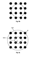
Fig. 4b shows an example constellation diagram for 16QAM modulation; -
Fig. 4c illustrates a plurality of example constellation circles used for the determination of a plurality of error functions; and -
Fig. 5 illustrates an example implementation of a threshold directed multi modulus algorithm. - In fiber-optic communications, wavelength-division multiplexing (WDM) is a technology which multiplexes multiple optical carrier signals on a single optical fiber by using different wavelengths (colors) of laser light to carry different signals. This allows for a multiplication in capacity, in addition to enabling bidirectional communications over one strand of fiber.
Fig. 1 illustrates an optical transmission system comprising anoptical transmitter 50, an optical transmission path 60 (e.g. an optical fiber) and anoptical receiver 70. - At an
optical transmitter 50 an optical carrier of a certain wavelength is modulated with a certain modulation scheme, in order to transmit data to the correspondingoptical receiver 70. Different modulation schemes may be used for this purpose, such as B-PSK (binary phase-shift keying) which maps one bit of data into a symbol, Q-PSK (quadrature phase-shift keying) which maps 2 bits of data into a symbol, M-PSK which maps log2(M) bits of data into a symbol. Furthermore, x-QAM (quadrature amplitude modulation) schemes may be used, wherein x represents the number of constellation points on the QAM grid. Typical forms of QAM are 16-QAM, 64-QAM, 128-QAM and 256-QAM. QAM modulation schemes modulate the amplitude and the phase of the optical carrier. - Subsequent to modulation, the modulated optical carrier signal is transmitted over the
optical transmission network 60 oroptical transmission channel 60 to the correspondingreceiver 70. Typically, theoptical receiver 70 is a coherentoptical receiver 100 comprising acoherent mixer 110 for coherent detection of PSK or QAM modulated signals. An exemplarycoherent receiver 100 is shown schematically inFig. 1 . A receivedsignal 101 at a certain optical carrier frequency and anoptical signal 102 of the local oscillator (LO) at a certain local oscillator frequency are combined in thecoherent mixer 110, which generates four optical interference signals for fouroutput ports mixer 110 is typically designed such that, from one port to the next, the relative phase between the receivedoptical signal 101 and theLO signal 102 is rotated by 90°.Ports 111 & 113 and 112 & 114 are fed to two sets ofbalanced photodiodes coherent mixer 110 is used to generate optical signals that will create in-phase I and quadrature Q components after beating on the photodiodes. In other words, the combination of thecoherent mixer 110 and the photodiodes generate I and Q components. Due to the 90° degree rotation, two sets of in-phase and quadrature components may be obtained, wherein the two sets correspond to two distinct polarizations of the optical signal which are orthogonal with respect to one another. It is to be denoted that the methods and systems outlined in the present document can be applied to other types of coherent receivers and modulation formats involving amplitude and phase modulation. - The analog electrical in-phase and quadrature component of the optical signal are sampled with analog-to-digital converters (ADCs) 123, 124. The sampled digital signals are then processed in the digital domain by a digital signal processor (DSP) 125 to pre-process the digital signals and to eventually demodulate the transmitted data.
- An overview of such a coherent
optical receiver 100 is illustrated inFig. 2b where the 90°hybrid 110, the optical-to-electrical converters ADCs DSP 125 is shown. - The processing steps that may be performed on the digital received signals are outlined in further detail in
Fig. 2c. Fig. 2c illustrates an exemplary scenario of anoptical receiver 200 for polarization multiplexed optical signals, i.e. optical signals comprising two orthogonally polarizedoptical signal components optical signal components 206 is considered in the following. - As mentioned above, the analog received signals are converted into digital
signals using ADCs 201, thereby yielding digital received signals comprising an in-phase and a quadrature component. The samples of the two digital signal components in a time slot n may be converted from cartesian coordinates into polar coordinates in aconversion unit 202. As such, samples or symbols of the received signal in a time slot n may be obtained which can be described by an amplitude and by a phase. The samples or symbols of the received signal for a plurality of time slots are plotted in the diagram 210. - As part of the digital signal processing, compensation of linear-distortion effects, e.g. chromatic dispersion (CD) and/or polarization mode distortion (PMD), may be performed. This may be performed in the
CD equalization unit 203. The outcome of the equalized symbols is illustrated in diagram 211. - If orthogonally polarized optical signals are received, then the
optical receiver 200 may comprise apolarization de-multiplexer 204 which aims at de-multiplexing the two orthogonally multiplexed signal components or polarization tributaries using an adaptive equalizer. The equalizer may use e.g. a constant modulo algorithm (CMA) or decision directed algorithms as will be outlined in further detail below. As an outcome, de-multiplexed symbols are obtained as illustrated in diagram 212. - The
optical receiver 200 may also comprise a carrier phase recovery andcompensation unit 220. The inputs to the carrier phase recovery andcompensation unit 220 are possibly pre-processed symbols which comprise an amplitude and a phase. The phase of the symbols at the transmitter comprises the phase of the optical carrier. This carrier phase may be submitted to various distortion effects within theoptical transmission channel 60. Consequently, at theoptical receiver 200, this carrier phase may be unknown and continuously changing. As such, the carrier phase recovery andcompensation unit 220 comprises a carrierphase estimation unit 221 which continuously estimates the carrier phase. The estimated carrier phase may be used to synchronize the phase of the local oscillator (LO) accordingly and to thereby compensate the carrier phase fluctuations directly at the coherentoptical receiver 100 in the optical domain. Alternatively or in addition, the carrier phase fluctuations may be compensated in the digital domain in thecompensation unit 222. As an outcome symbols with a compensated carrier phase are obtained as illustrated in diagram 213. - It can be seen that the received and digitally processed symbols shown in diagram 213 are grouped into four clusters corresponding to the constellation points of a Q-PSK modulation. In other words, the constellation of the symbol states has been fixed as an outcome of the compensation of the carrier phase fluctuations.
- Subsequently, the digitally processed symbols are submitted to the
symbol identification unit 205 which performs the mapping of the digitally processed symbols to the constellation points of the underlying modulation scheme. - In the following, the
polarization de-multiplexer 204 will be described in further detail. The polarization de-multiplexer 204 typically comprises a butterfly filter comprising four feed forward equalizers (FFE) as illustrated inFig. 3 . Each FFE may comprise a finite impulse response filter (FIR) of the type
and in a similar manner for Hxy (z), Hyx (z) and Hyy (z). It should be noted that thepolarization de-multiplexer 204 comprising FIR filters may perform the function of CD/PMD equalization unit 203, i.e. the polarization de-multiplexer may perform an equalization of theoptical transmission channel 60. Furthermore, thepolarization de-multiplexer 204 may have a delay function and thereby adapt the sampling time instants. For this purpose, the input signal to thepolarization de-multiplexer 204 may be over-sampled (at a sampling rate higher than the signal rate), wherein the output of thepolarization de-multiplexer 204 may be sampled at the signal rate. As such, thepolarization de-multiplexer 204 may be referred to more generally as anequalization unit 204. More generally, it may be stated that the methods outlined in the present document apply togeneric equalization units 204 comprising e.g. only a single FFE. - The parameters of the feed forward equalizers may be determined by the use of training data and/or by adaptive optimization schemes exploiting known characteristics of the received polarization division multiplexed (PDM) signal, wherein the latter scheme is also referred to as blind equalization. For the determination of the equalization parameters in a blind equalizer, the so-called constant modulus algorithm (CMA) may be used to adapt the FIR taps

- The CMA algorithm was introduced by Godard (IEEE Tr. Comm, vol.28, no.11. pp. 1867-1875, 1980.). Furthermore, The CMA is discussed in the document "Digital Equalisation of 40Gbit/s per Wavelength Transmission over 2480km of Standard Fibre without Optical Dispersion Compensation", S.J. Savory et al., Proceedings of ECOC 2006, Cannes, France, paper Th2.5.5, Sep. 2006.
- For signals of unit amplitude, the CMA tries to minimize the magnitude of the error term E=(|sout |-1)2, wherein |sout | is the intensity (or amplitude) of an output signal sout of the equalization stage. In the present case, the signal sout may be the output signal of the
polarization de-multiplexer 204, e.g. sout=Iχ +jQχ and/or sout=Iy+jQy inFig. 3 . - According to the CMA, the tap coefficients


- Here, the term


polarization de-multiplexer 204 may be e.g. sin =qx +jqx and/or sin =iy +jqy inFig. 3 . As such, the CMA determines and adapts the FIR filter coefficients in an iterative manner. - As indicated above, the CMA has been described for signals having unit amplitude, i.e. for signals which have been modulated using modulation schemes which do not perform amplitude modulation. As such, the CMA can be used in the context of PSK modulated signals. For example, in case of QPSK modulation all constellation points are located exactly on the unit circle (if neglecting noise). This is illustrated in
Fig. 4a . - However, in order to further increase the bitrate per channel, higher level modulation schemes may need to be applied, e.g. 16QAM instead of QPSK modulation. As illustrated in
Fig. 4b , none of the constellation points of 16QAM are located on the unit circle. CMA may still be applied, the fact that the constellation points have a systematic deviation from the unity circle, will lead to fluctuations during filter adaptation. Furthermore, the adaptation speed, accuracy and stability of the CMA are affected. - In view of these systematic deviations, a modified algorithm for iterative FIR filter coefficient determination and adaptation is proposed. In particular, it is proposed to define a plurality of circles, e.g. two circles, and to consider the deviation from these circles when adapting the filter coefficients. The adaptation of the filter coefficient may be performing by using a constant modulus algorithm as outlined above. By way of example, in the context of 16 QAM, a first, inner, circle and a second, outer, circle may be defined. The inner circle may be defined using the inner 4 constellation points of the 16QAM constellation. Furthermore, the second, outer, circle may be defined for the outer 4 constellation points of the 16QAM constellation. This is illustrated in
Fig. 4c where theinner circle 410 and theouter circle 420 for a 16 QAM constellation are illustrated. As such, theinner circle 410 traverses the constellation points having the lowest amplitude and theouter circle 420 traverses the constellation points having the highest amplitude. - Using the two
circles 

- In order to attribute output samples sout to the first or second circle, i.e. to the first or second error term, one may consider only a subset of output samples sout for the determination of the error terms. By way of example, only the output samples lying within the inner circle may be considered for determining the first error term E 1 associated with the inner circle T 1, and only the output samples lying outside of the outer circle T 2 may be considered for determining the second error term E 2. The output samples lying in-between both circuits may be neglected.
- The plurality of error terms E 1 and E 2 which are associated with the plurality of circles T 1 and T 2, respectively, may be used to define a modified constant modulus algorithm. The new algorithm may be referred to as threshold directed multi modulus algorithm (TD-MMA). In a similar manner to the CMA, the error terms E 1 and E 2 can be used to calculate updated FIR filter coefficients

- However, in contrary to the constant modulus algorithm, where a single unit circle is assumed, the radius of the
circles - An example implementation of the TD-MMA algorithm including a control mechanism for the parameters T 1, T 2 and m is illustrated in
Fig. 5 . An example feedforward equalizer 501, e.g. one of the four FFEs ofFig. 3 , is shown. The input signal sin may be sin =qx +jqx or sin =iy +jqy , and the output signal sout may be sout =Ix +jQx or sout =Iy +jQy ofFig. 3 . As such, theFFE 501 may be one of the FIR filters Hxx (z), Hxy (z), Hyx (z) or Hyy (z). - The FIR filter coefficients are determined using a constant modulus algorithm in the TD-
MMA unit 502, wherein the overall error term E is determined from a combination of the first and second error terms E 1, and E 2, e.g. E = E 1 + E 2. In order to determine the first and second error term E 1 and E 2, the TD-MMA unit 502 proceeds as outlined above, i.e.

inner circle 410, and for the determination of E 2 only output signal samples lying outside of theouter circle 420 are considered. The TD-MMA unit 502 may also be referred to as filtercoefficient update unit 502. - Appropriate values for the circle radii T 1, T 2 and for the weighting parameter m may be determined by an
adaptation unit 510 for the MMA parameters, i.e. for T 1, T 2 and m (also referred to as a threshold orradius adaption unit 510 in the present document). In other words, theadaptation unit 510 for MMA parameters may control the two circle diameters and/or a weighting factor for the error terms. - The
adaptation unit 510 comprises a plurality ofcounter units first counter unit 503 counts the number of samples of sout with a magnitude or amplitude smaller than the first threshold or circle radius T 1. In other words, thefirst counter unit 503 counts the number of samples which lie within the first, inner, circle. Thesecond counter unit 504 counts the number of samples of sout with a magnitude or amplitude greater than the second threshold or circle radius T 2. In other words, thesecond counter unit 504 counts the number of samples which lie outside of the second, outer, circle. Atotal counter unit 505 determines the overall number of investigated samples of sout . Thecounter units - The counts a, b, c are passed to a
verification unit 506 which determines the relative ratios a/c and b/c. The first ratio a/c indicates the fraction of samples of sout which lie within theinner circle 410. The second ratio b/c indicates the fraction of samples of sout which lie outside of theouter circle 420. These ratios are compared to their respective target values or target indicators. It can be seen inFig. 4c that in the case of 16QAM, four out of 16 samples should lie inside theinner circle 410 50% of the time, i.e. the first target value target1 should be 50% of 1/4, i.e. 1/8. Furthermore, it can be seen that four out of 16 samples should lie outside of theouter circle 420 50% of the time, i.e. the second target value target2 should also be 1/8. - The
verification unit 506 may determine other indicators which indicate a deviation of the radii or thresholds T 1 and T 2 from their target value. In particular theverification unit 506 may count the amount of deviations from the inner threshold T1 and the amount of deviations from the outer threshold T2. Subsequently the amounts may be divided to determine a ratio a/b. This ratio a/b may be compared to a target value target3. In other words, a ratio a/b, i.e. the ratio of the number of samples lying inside the inner circle and the number of samples lying outside the outer sample, may be determined. This ratio a/b is compared to a target value target3, which in the case of 16QAM should be 1. If the ratio a/b is greater than the target value target3, then the radii or thresholds T 1 and T 2 could be increased and vice versa. Alternatively or in addition, the weighting parameter m may be controlled based on the ratio a/b. The weighting parameter m may be increased if the ratio a/b is greater than the target value target3 and/or vice versa. - The different ratios and/or indicators may be used to determine one or more adaption parameters Δ, which are used in the
parameter update unit 507 to determine a new set of MMA parameters T 1, T 2 and/or m. By way of example, if the ratio a/c is lower than target1, the radius T 1 may be increased by a pre-determined adaption parameter Δ1, and vice versa. In a similar manner, if the ratio b/c is lower than target1, the radius T 2 may be decreased by a pre-determined adaption parameter Δ2, and vice versa. The weighting parameter m may be controlled using the ratio a/b. If the ratio a/b exceeds target3 the weighting parameter m may be increased by a pre-determined adaption parameter Δ3, and vice versa. As such, more emphasis can be put on the first error term E 1 and vice versa. - In an embodiment, the one or more pre-determined adaption parameters Δ may be controlled. By way of example, the adaption parameters Δ may be increased and/or decreased depending on the extent of deviation of the determined ratios a/c, b/c and/or a/b from the respective target values target1, target2 and/or target3. If the extent of deviation is above a certain threshold, the adaption parameters Δ may be increased and/or vice versa.
- In the present document, a method and system for performing equalization of an optical transmission channel has been described. In particular, a method for determining appropriate equalization parameters for polarization de-multiplexing has been described. This method is applicable to high order modulation schemes having constellation points which do not lie on a single unit circle, such as 16 QAM or higher. The described method does not incur any systematic deviations and thereby ensures optimum performance, a high degree of stability and high adaptation speed. The polarization de-multiplexer outlined in the present document is particularly well suited for use in optical transmission systems at 100 Gb/s data rate and beyond.
- It should be noted that the description and drawings merely illustrate the principles of the proposed methods and systems. It will thus be appreciated that those skilled in the art will be able to devise various arrangements that, although not explicitly described or shown herein, embody the principles of the invention and are included within its spirit and scope. Furthermore, all examples recited herein are principally intended expressly to be only for pedagogical purposes to aid the reader in understanding the principles of the proposed methods and systems and the concepts contributed by the inventors to furthering the art, and are to be construed as being without limitation to such specifically recited examples and conditions. Moreover, all statements herein reciting principles, aspects, and embodiments of the invention, as well as specific examples thereof, are intended to encompass equivalents thereof.
- Furthermore, it should be noted that steps of various above-described methods and components of described systems can be performed by programmed computers. Herein, some embodiments are also intended to cover program storage devices, e.g., digital data storage media, which are machine or computer readable and encode machine-executable or computer-executable programs of instructions, wherein said instructions perform some or all of the steps of said above-described methods. The program storage devices may be, e.g., digital memories, magnetic storage media such as a magnetic disks and magnetic tapes, hard drives, or optically readable digital data storage media. The embodiments are also intended to cover computers programmed to perform said steps of the above-described methods.
- In addition, it should be noted that the functions of the various elements described in the present patent document may be provided through the use of dedicated hardware as well as hardware capable of executing software in association with appropriate software. When provided by a processor, the functions may be provided by a single dedicated processor, by a single shared processor, or by a plurality of individual processors, some of which may be shared. Moreover, explicit use of the term "processor" or "controller" should not be construed to refer exclusively to hardware capable of executing software, and may implicitly include, without limitation, digital signal processor (DSP) hardware, network processor, application specific integrated circuit (ASIC), field programmable gate array (FPGA), read only memory (ROM) for storing software, random access memory (RAM), and non volatile storage. Other hardware, conventional and/or custom, may also be included.
- Finally, it should be noted that any block diagrams herein represent conceptual views of illustrative circuitry embodying the principles of the invention. Similarly, it will be appreciated that any flow charts, flow diagrams, state transition diagrams, pseudo code, and the like represent various processes which may be substantially represented in computer readable medium and so executed by a computer or processor, whether or not such computer or processor is explicitly shown.
Claims (15)
- An equalizing unit (125, 203, 204) for an input signal, wherein the input signal has been amplitude and phase modulated using a modulation scheme, and transmitted over a transmission channel; the equalizing unit (125, 203, 204) comprising:- a filter (501) adapted to filter the input signal using one or more filter taps, thereby yielding an output signal; wherein the output signal comprises a plurality of output samples having a plurality of output amplitudes, respectively; and- a filter adaption unit (502) adapted to- determine a first deviation of the output amplitude of at least some of the plurality of output samples from a first threshold;- determine a second deviation of the output amplitude of at least some of the plurality of output samples from a second threshold; wherein the second threshold is greater than the first threshold and wherein the first threshold and the second threshold are associated with a first constellation amplitude and second constellation amplitude of constellation points of the modulation scheme, respectively; and- update the one or more filter taps based on the first and second deviations.
- The equalization unit (125, 203, 204) of claim 1, wherein the filter adaption unit (502) is adapted to- determine the first deviation considering only output samples having an output amplitude smaller or equal to the first threshold; and- determine the second deviation considering only output samples having an output amplitude greater or equal to the second threshold.
- The equalization unit (125, 203, 204) of any previous claim, wherein the filter adaption unit (502) is adapted to- update the one or more filter taps using a weighted sum of the first and second deviation.
- The equalization unit (125, 203, 204) of any previous claim, wherein the filter adaption unit (502) is adapted to- update the one or more filter taps using a constant modulus algorithm.
- The equalization unit (125, 203, 204) of any previous claim, further comprising:- a threshold adaption unit (510) adapted to update the first and second thresholds based on the plurality of output amplitudes.
- The equalization unit (125, 203, 204) of claim 5, wherein the threshold adaption unit (510) is adapted to- determine a first indicator of an amount of output samples having an output amplitude smaller or equal to the first threshold;- determine a second indicator of an amount of output samples having an output amplitude greater or equal to the second threshold; and- update the first and second threshold based on the first and second indicators.
- The equalization unit (125, 203, 204) of claim 6, wherein- the first indicator indicates the portion of output samples from the plurality of output samples which have an output amplitude smaller or equal to the first threshold; and- the second indicator indicates the portion of output samples from the plurality of output samples which have an output amplitude greater or equal to the second threshold.
- The equalization unit (125, 203, 204) of any of claims 6 to 7, wherein- the threshold adaption unit (510) is adapted to compare the first and second indicators with a first and a second target indicator; and- the first target indicator is indicative of a probability for an output sample to have an output amplitude smaller or equal to the first constellation amplitude, and/or- the second target indicator is indicative of a probability for an output sample to have an output amplitude greater or equal to the second constellation amplitude.
- The equalization unit (125, 203, 204) of claim 8, wherein- the first threshold is decreased, if the first indicator is higher than the first target indicator; and/or- the second threshold is increased, if the second indicator is higher than the second target indicator.
- The equalization unit (125, 203, 204) of any of claims 8 to 9, referring back to claim 3, wherein- the threshold adaption unit (510) is adapted to determine a weight based on the first and second indicators; and- the weight is used to determine the weighted sum of the first and second deviations.
- The equalization unit (125, 203, 204) of claim 10, wherein- the weight is applied to the first deviation; and- the weight is increased, if a ratio of the first indicator over the second indicator is higher than a ratio of the first target indicator over the second target indicator.
- The equalization unit (125, 203, 204) of any previous claim, wherein- the input signal is derived from an optical signal received at a coherent optical receiver;- the modulation scheme is any one of 16QAM, 64 QAM, 128QAM, 256QAM or a other higher level modulation scheme;- the first constellation amplitude is the smallest amplitude of constellation points of the modulation scheme; and/or- the second constellation amplitude is the highest amplitude of constellation points of the modulation scheme.
- The equalization unit (125, 203, 204) of any previous claim, wherein the equalization unit (125, 203, 204) is adapted to perform one or more of- polarization de-multiplexing of the input signal; and/or- equalization of chromatic dispersion and/or polarization mode dispersion incurred by the input signal on the transmission channel; and/or.- equalization of degradations from systems bandwidth limitations; and/or- adjusting of a variable signal delay for resampling of data at an optimized phase.
- A coherent optical receiver (100), comprising- a coherent mixer (110) adapted to- superimpose a received optical signal (101) with an optical signal (102) generated by a local oscillator; and- generate two sets of in-phase and quadrature phase signals, the two sets having orthogonal polarizations with respect to one another;- an optical to digital conversion unit (121, 122, 123, 124) adapted to convert the two sets of in-phase and quadrature phase signals into two digital complex input signals, respectively; wherein the two input signals comprise a plurality of input samples having a plurality of input amplitudes, respectively; and- an equalization unit (125, 203, 204) according to any of claims 1 to 13, adapted to polarization de-multiplex and/or equalize the two input signals.
- A method for equalizing an input signal, wherein the input signal has been amplitude and phase modulated using a modulation scheme and transmitted over a transmission channel; the method comprising:- filtering the input signal using one or more filter taps, thereby yielding an output signal; wherein the output signal comprises a plurality of output samples having a plurality of output amplitudes, respectively;- determining a first deviation of the output amplitude of at least some of the plurality of output samples from a first threshold;- determining a second deviation of the output amplitude of at least some of the plurality of output samples from a second thresholds; wherein the second threshold is greater than the first threshold and wherein the first and second threshold are associated with a first constellation amplitude and second constellation amplitude of constellation points of the modulation scheme, respectively; and- updating the one or more filter taps based on the first and second deviations.
Priority Applications (1)
| Application Number | Priority Date | Filing Date | Title |
|---|---|---|---|
| EP11290070.9A EP2487813B1 (en) | 2011-02-01 | 2011-02-01 | Polarization de-multiplex for multilevel signals |
Applications Claiming Priority (1)
| Application Number | Priority Date | Filing Date | Title |
|---|---|---|---|
| EP11290070.9A EP2487813B1 (en) | 2011-02-01 | 2011-02-01 | Polarization de-multiplex for multilevel signals |
Publications (2)
| Publication Number | Publication Date |
|---|---|
| EP2487813A1 EP2487813A1 (en) | 2012-08-15 |
| EP2487813B1 true EP2487813B1 (en) | 2013-04-17 |
Family
ID=44263220
Family Applications (1)
| Application Number | Title | Priority Date | Filing Date |
|---|---|---|---|
| EP11290070.9A Active EP2487813B1 (en) | 2011-02-01 | 2011-02-01 | Polarization de-multiplex for multilevel signals |
Country Status (1)
| Country | Link |
|---|---|
| EP (1) | EP2487813B1 (en) |
Cited By (2)
| Publication number | Priority date | Publication date | Assignee | Title |
|---|---|---|---|---|
| US9553754B1 (en) | 2015-09-10 | 2017-01-24 | Qualcomm Incorporated | Post distortion in satellite communications |
| CN107018103A (en) * | 2017-04-07 | 2017-08-04 | 淮南职业技术学院 | A kind of small echo norm blind balance method based on the group's optimization of adaptive step monkey |
Families Citing this family (1)
| Publication number | Priority date | Publication date | Assignee | Title |
|---|---|---|---|---|
| CN110311878B (en) * | 2019-05-28 | 2021-11-19 | 西南电子技术研究所(中国电子科技集团公司第十研究所) | Synchronous detection method for locking state of 16QAM carrier demodulation loop |
Family Cites Families (3)
| Publication number | Priority date | Publication date | Assignee | Title |
|---|---|---|---|---|
| WO2005117285A1 (en) * | 2004-05-28 | 2005-12-08 | Mitsubishi Denki Kabushiki Kaisha | Distortion compensation equalizer |
| JP4620642B2 (en) * | 2006-07-31 | 2011-01-26 | 富士通株式会社 | Multilevel modulation receiver |
| JP5061855B2 (en) * | 2007-11-07 | 2012-10-31 | 富士通株式会社 | Electrical dispersion compensation device, optical receiver, and optical reception method |
-
2011
- 2011-02-01 EP EP11290070.9A patent/EP2487813B1/en active Active
Cited By (3)
| Publication number | Priority date | Publication date | Assignee | Title |
|---|---|---|---|---|
| US9553754B1 (en) | 2015-09-10 | 2017-01-24 | Qualcomm Incorporated | Post distortion in satellite communications |
| CN107018103A (en) * | 2017-04-07 | 2017-08-04 | 淮南职业技术学院 | A kind of small echo norm blind balance method based on the group's optimization of adaptive step monkey |
| CN107018103B (en) * | 2017-04-07 | 2020-02-14 | 淮南职业技术学院 | Wavelet constant modulus blind equalization method based on adaptive step size monkey swarm optimization |
Also Published As
| Publication number | Publication date |
|---|---|
| EP2487813A1 (en) | 2012-08-15 |
Similar Documents
| Publication | Publication Date | Title |
|---|---|---|
| US9912500B2 (en) | Adaptive pre-equalization in optical communications | |
| US8873968B2 (en) | Optical field receiver, optical multilevel signal receiver, and optical transmission system | |
| JP5351342B2 (en) | Carrier phase estimator for nonlinear fault monitoring and mitigation in coherent optical systems | |
| US9515742B2 (en) | System and methods for adaptive equalization for optical modulation formats | |
| US9692548B2 (en) | Techniques for blind equalization of high-order quadrature amplitude modulation signals | |
| JP6127848B2 (en) | Equalizer coefficient updating apparatus, method, receiver, and optical communication system | |
| JP5898374B2 (en) | Nonlinear cross polarization mitigation algorithm | |
| US8442406B2 (en) | Filter, coherent receiver device and coherent receiving method | |
| US9166703B2 (en) | Equalizer for an optical transmission system | |
| JP5943001B2 (en) | Equalized signal processing apparatus, optical receiver using the same, and equalized signal processing method | |
| CN107852248B (en) | Signal processing apparatus and method in optical receiver | |
| JP2015510366A (en) | Apparatus and method for wavelength dispersion processing | |
| JP5312384B2 (en) | Digital sample processing method, digital sample processing apparatus, and program | |
| Xu et al. | Joint scheme of dynamic polarization demultiplexing and PMD compensation up to second order for flexible receivers | |
| EP2487813B1 (en) | Polarization de-multiplex for multilevel signals | |
| Zhu et al. | Frequency-domain blind equalization for long-haul coherent pol-mux 16-QAM system with CD prediction and dual-mode adaptive algorithm | |
| CN111869157B (en) | Timing recovery apparatus and timing recovery method for use in data transmission system | |
| US11967996B2 (en) | Frequency domain equalization method, equalizer, optical receiver, and system | |
| US20220321232A1 (en) | Frequency domain equalization method, equalizer, optical receiver, and system | |
| EP4099584B1 (en) | Mitigation of equalization-enhanced phase noise in a coherent optical receiver | |
| WO2023248285A1 (en) | Multicarrier signal waveform equalization circuit and multicarrier signal waveform equalization method | |
| US20230085546A1 (en) | Perturbative-based nonlinear compensation for digital subcarrier systems | |
| EP2362557B1 (en) | MLSE in coherent optical receiver for optical filtering tolerance | |
| Khalil et al. | Efficient FIR filter configuration to joint IQ imbalance and carrier-phase recovery in 16-QAM coherent receivers | |
| Hossain et al. | Partitioned Multi-Modulus Algorithm for Blind Equalization and Carrier Phase Recovery of Optical Hexagonal 16-QAM Transmission Systems |
Legal Events
| Date | Code | Title | Description |
|---|---|---|---|
| PUAI | Public reference made under article 153(3) epc to a published international application that has entered the european phase |
Free format text: ORIGINAL CODE: 0009012 |
|
| 17P | Request for examination filed |
Effective date: 20110823 |
|
| AK | Designated contracting states |
Kind code of ref document: A1 Designated state(s): AL AT BE BG CH CY CZ DE DK EE ES FI FR GB GR HR HU IE IS IT LI LT LU LV MC MK MT NL NO PL PT RO RS SE SI SK SM TR |
|
| AX | Request for extension of the european patent |
Extension state: BA ME |
|
| GRAP | Despatch of communication of intention to grant a patent |
Free format text: ORIGINAL CODE: EPIDOSNIGR1 |
|
| GRAS | Grant fee paid |
Free format text: ORIGINAL CODE: EPIDOSNIGR3 |
|
| REG | Reference to a national code |
Ref country code: DE Ref legal event code: R079 Ref document number: 602011001392 Country of ref document: DE Free format text: PREVIOUS MAIN CLASS: H04B0010148000 Ipc: H04L0025030000 |
|
| GRAA | (expected) grant |
Free format text: ORIGINAL CODE: 0009210 |
|
| RIC1 | Information provided on ipc code assigned before grant |
Ipc: H04B 10/25 20130101ALI20130306BHEP Ipc: H04B 10/60 20130101ALI20130306BHEP Ipc: H04L 25/03 20060101AFI20130306BHEP |
|
| AK | Designated contracting states |
Kind code of ref document: B1 Designated state(s): AL AT BE BG CH CY CZ DE DK EE ES FI FR GB GR HR HU IE IS IT LI LT LU LV MC MK MT NL NO PL PT RO RS SE SI SK SM TR |
|
| REG | Reference to a national code |
Ref country code: GB Ref legal event code: FG4D |
|
| REG | Reference to a national code |
Ref country code: CH Ref legal event code: EP |
|
| REG | Reference to a national code |
Ref country code: IE Ref legal event code: FG4D |
|
| REG | Reference to a national code |
Ref country code: AT Ref legal event code: REF Ref document number: 607880 Country of ref document: AT Kind code of ref document: T Effective date: 20130515 |
|
| REG | Reference to a national code |
Ref country code: DE Ref legal event code: R096 Ref document number: 602011001392 Country of ref document: DE Effective date: 20130606 |
|
| REG | Reference to a national code |
Ref country code: AT Ref legal event code: MK05 Ref document number: 607880 Country of ref document: AT Kind code of ref document: T Effective date: 20130417 |
|
| REG | Reference to a national code |
Ref country code: LT Ref legal event code: MG4D |
|
| 111Z | Information provided on other rights and legal means of execution |
Free format text: AL AT BE BG CH CY CZ DE DK EE ES FI FR GB GR HR HU IE IS IT LI LT LU LV MC MK MT NL NO PL PT RO RS SE SI SK SM TR Effective date: 20130410 |
|
| REG | Reference to a national code |
Ref country code: NL Ref legal event code: VDEP Effective date: 20130417 |
|
| PG25 | Lapsed in a contracting state [announced via postgrant information from national office to epo] |
Ref country code: BE Free format text: LAPSE BECAUSE OF FAILURE TO SUBMIT A TRANSLATION OF THE DESCRIPTION OR TO PAY THE FEE WITHIN THE PRESCRIBED TIME-LIMIT Effective date: 20130417 Ref country code: ES Free format text: LAPSE BECAUSE OF FAILURE TO SUBMIT A TRANSLATION OF THE DESCRIPTION OR TO PAY THE FEE WITHIN THE PRESCRIBED TIME-LIMIT Effective date: 20130728 Ref country code: NO Free format text: LAPSE BECAUSE OF FAILURE TO SUBMIT A TRANSLATION OF THE DESCRIPTION OR TO PAY THE FEE WITHIN THE PRESCRIBED TIME-LIMIT Effective date: 20130717 Ref country code: IS Free format text: LAPSE BECAUSE OF FAILURE TO SUBMIT A TRANSLATION OF THE DESCRIPTION OR TO PAY THE FEE WITHIN THE PRESCRIBED TIME-LIMIT Effective date: 20130817 Ref country code: FI Free format text: LAPSE BECAUSE OF FAILURE TO SUBMIT A TRANSLATION OF THE DESCRIPTION OR TO PAY THE FEE WITHIN THE PRESCRIBED TIME-LIMIT Effective date: 20130417 Ref country code: SI Free format text: LAPSE BECAUSE OF FAILURE TO SUBMIT A TRANSLATION OF THE DESCRIPTION OR TO PAY THE FEE WITHIN THE PRESCRIBED TIME-LIMIT Effective date: 20130417 Ref country code: PT Free format text: LAPSE BECAUSE OF FAILURE TO SUBMIT A TRANSLATION OF THE DESCRIPTION OR TO PAY THE FEE WITHIN THE PRESCRIBED TIME-LIMIT Effective date: 20130819 Ref country code: SE Free format text: LAPSE BECAUSE OF FAILURE TO SUBMIT A TRANSLATION OF THE DESCRIPTION OR TO PAY THE FEE WITHIN THE PRESCRIBED TIME-LIMIT Effective date: 20130417 Ref country code: GR Free format text: LAPSE BECAUSE OF FAILURE TO SUBMIT A TRANSLATION OF THE DESCRIPTION OR TO PAY THE FEE WITHIN THE PRESCRIBED TIME-LIMIT Effective date: 20130718 Ref country code: LT Free format text: LAPSE BECAUSE OF FAILURE TO SUBMIT A TRANSLATION OF THE DESCRIPTION OR TO PAY THE FEE WITHIN THE PRESCRIBED TIME-LIMIT Effective date: 20130417 Ref country code: AT Free format text: LAPSE BECAUSE OF FAILURE TO SUBMIT A TRANSLATION OF THE DESCRIPTION OR TO PAY THE FEE WITHIN THE PRESCRIBED TIME-LIMIT Effective date: 20130417 |
|
| PG25 | Lapsed in a contracting state [announced via postgrant information from national office to epo] |
Ref country code: BG Free format text: LAPSE BECAUSE OF FAILURE TO SUBMIT A TRANSLATION OF THE DESCRIPTION OR TO PAY THE FEE WITHIN THE PRESCRIBED TIME-LIMIT Effective date: 20130717 Ref country code: HR Free format text: LAPSE BECAUSE OF FAILURE TO SUBMIT A TRANSLATION OF THE DESCRIPTION OR TO PAY THE FEE WITHIN THE PRESCRIBED TIME-LIMIT Effective date: 20130417 Ref country code: CY Free format text: LAPSE BECAUSE OF FAILURE TO SUBMIT A TRANSLATION OF THE DESCRIPTION OR TO PAY THE FEE WITHIN THE PRESCRIBED TIME-LIMIT Effective date: 20130417 Ref country code: LV Free format text: LAPSE BECAUSE OF FAILURE TO SUBMIT A TRANSLATION OF THE DESCRIPTION OR TO PAY THE FEE WITHIN THE PRESCRIBED TIME-LIMIT Effective date: 20130417 Ref country code: RS Free format text: LAPSE BECAUSE OF FAILURE TO SUBMIT A TRANSLATION OF THE DESCRIPTION OR TO PAY THE FEE WITHIN THE PRESCRIBED TIME-LIMIT Effective date: 20130417 Ref country code: PL Free format text: LAPSE BECAUSE OF FAILURE TO SUBMIT A TRANSLATION OF THE DESCRIPTION OR TO PAY THE FEE WITHIN THE PRESCRIBED TIME-LIMIT Effective date: 20130417 |
|
| REG | Reference to a national code |
Ref country code: FR Ref legal event code: GC Effective date: 20131120 |
|
| PG25 | Lapsed in a contracting state [announced via postgrant information from national office to epo] |
Ref country code: EE Free format text: LAPSE BECAUSE OF FAILURE TO SUBMIT A TRANSLATION OF THE DESCRIPTION OR TO PAY THE FEE WITHIN THE PRESCRIBED TIME-LIMIT Effective date: 20130417 Ref country code: DK Free format text: LAPSE BECAUSE OF FAILURE TO SUBMIT A TRANSLATION OF THE DESCRIPTION OR TO PAY THE FEE WITHIN THE PRESCRIBED TIME-LIMIT Effective date: 20130417 Ref country code: SK Free format text: LAPSE BECAUSE OF FAILURE TO SUBMIT A TRANSLATION OF THE DESCRIPTION OR TO PAY THE FEE WITHIN THE PRESCRIBED TIME-LIMIT Effective date: 20130417 Ref country code: CZ Free format text: LAPSE BECAUSE OF FAILURE TO SUBMIT A TRANSLATION OF THE DESCRIPTION OR TO PAY THE FEE WITHIN THE PRESCRIBED TIME-LIMIT Effective date: 20130417 |
|
| PLBE | No opposition filed within time limit |
Free format text: ORIGINAL CODE: 0009261 |
|
| STAA | Information on the status of an ep patent application or granted ep patent |
Free format text: STATUS: NO OPPOSITION FILED WITHIN TIME LIMIT |
|
| PG25 | Lapsed in a contracting state [announced via postgrant information from national office to epo] |
Ref country code: RO Free format text: LAPSE BECAUSE OF FAILURE TO SUBMIT A TRANSLATION OF THE DESCRIPTION OR TO PAY THE FEE WITHIN THE PRESCRIBED TIME-LIMIT Effective date: 20130417 Ref country code: IT Free format text: LAPSE BECAUSE OF FAILURE TO SUBMIT A TRANSLATION OF THE DESCRIPTION OR TO PAY THE FEE WITHIN THE PRESCRIBED TIME-LIMIT Effective date: 20130417 Ref country code: NL Free format text: LAPSE BECAUSE OF FAILURE TO SUBMIT A TRANSLATION OF THE DESCRIPTION OR TO PAY THE FEE WITHIN THE PRESCRIBED TIME-LIMIT Effective date: 20130417 |
|
| 26N | No opposition filed |
Effective date: 20140120 |
|
| REG | Reference to a national code |
Ref country code: DE Ref legal event code: R097 Ref document number: 602011001392 Country of ref document: DE Effective date: 20140120 |
|
| REG | Reference to a national code |
Ref country code: CH Ref legal event code: PCOW Free format text: NEW ADDRESS: 148/152 ROUTE DE LA REINE, 92100 BOULOGNE-BILLANCOURT (FR) |
|
| PG25 | Lapsed in a contracting state [announced via postgrant information from national office to epo] |
Ref country code: MC Free format text: LAPSE BECAUSE OF FAILURE TO SUBMIT A TRANSLATION OF THE DESCRIPTION OR TO PAY THE FEE WITHIN THE PRESCRIBED TIME-LIMIT Effective date: 20130417 Ref country code: LU Free format text: LAPSE BECAUSE OF FAILURE TO SUBMIT A TRANSLATION OF THE DESCRIPTION OR TO PAY THE FEE WITHIN THE PRESCRIBED TIME-LIMIT Effective date: 20140201 |
|
| REG | Reference to a national code |
Ref country code: CH Ref legal event code: PL |
|
| PG25 | Lapsed in a contracting state [announced via postgrant information from national office to epo] |
Ref country code: CH Free format text: LAPSE BECAUSE OF NON-PAYMENT OF DUE FEES Effective date: 20140228 Ref country code: LI Free format text: LAPSE BECAUSE OF NON-PAYMENT OF DUE FEES Effective date: 20140228 |
|
| REG | Reference to a national code |
Ref country code: FR Ref legal event code: RG Effective date: 20141016 |
|
| REG | Reference to a national code |
Ref country code: IE Ref legal event code: MM4A |
|
| PG25 | Lapsed in a contracting state [announced via postgrant information from national office to epo] |
Ref country code: IE Free format text: LAPSE BECAUSE OF NON-PAYMENT OF DUE FEES Effective date: 20140201 |
|
| REG | Reference to a national code |
Ref country code: FR Ref legal event code: PLFP Year of fee payment: 5 |
|
| REG | Reference to a national code |
Ref country code: FR Ref legal event code: PLFP Year of fee payment: 6 |
|
| PG25 | Lapsed in a contracting state [announced via postgrant information from national office to epo] |
Ref country code: MT Free format text: LAPSE BECAUSE OF FAILURE TO SUBMIT A TRANSLATION OF THE DESCRIPTION OR TO PAY THE FEE WITHIN THE PRESCRIBED TIME-LIMIT Effective date: 20130417 |
|
| PG25 | Lapsed in a contracting state [announced via postgrant information from national office to epo] |
Ref country code: SM Free format text: LAPSE BECAUSE OF FAILURE TO SUBMIT A TRANSLATION OF THE DESCRIPTION OR TO PAY THE FEE WITHIN THE PRESCRIBED TIME-LIMIT Effective date: 20130417 |
|
| PG25 | Lapsed in a contracting state [announced via postgrant information from national office to epo] |
Ref country code: HU Free format text: LAPSE BECAUSE OF FAILURE TO SUBMIT A TRANSLATION OF THE DESCRIPTION OR TO PAY THE FEE WITHIN THE PRESCRIBED TIME-LIMIT; INVALID AB INITIO Effective date: 20110201 Ref country code: TR Free format text: LAPSE BECAUSE OF FAILURE TO SUBMIT A TRANSLATION OF THE DESCRIPTION OR TO PAY THE FEE WITHIN THE PRESCRIBED TIME-LIMIT Effective date: 20130417 |
|
| REG | Reference to a national code |
Ref country code: FR Ref legal event code: PLFP Year of fee payment: 7 |
|
| REG | Reference to a national code |
Ref country code: FR Ref legal event code: PLFP Year of fee payment: 8 |
|
| PG25 | Lapsed in a contracting state [announced via postgrant information from national office to epo] |
Ref country code: MK Free format text: LAPSE BECAUSE OF FAILURE TO SUBMIT A TRANSLATION OF THE DESCRIPTION OR TO PAY THE FEE WITHIN THE PRESCRIBED TIME-LIMIT Effective date: 20130417 |
|
| PG25 | Lapsed in a contracting state [announced via postgrant information from national office to epo] |
Ref country code: AL Free format text: LAPSE BECAUSE OF FAILURE TO SUBMIT A TRANSLATION OF THE DESCRIPTION OR TO PAY THE FEE WITHIN THE PRESCRIBED TIME-LIMIT Effective date: 20130417 |
|
| PGFP | Annual fee paid to national office [announced via postgrant information from national office to epo] |
Ref country code: GB Payment date: 20221230 Year of fee payment: 13 |
|
| PGFP | Annual fee paid to national office [announced via postgrant information from national office to epo] |
Ref country code: DE Payment date: 20221230 Year of fee payment: 13 |
|
| PGFP | Annual fee paid to national office [announced via postgrant information from national office to epo] |
Ref country code: FR Payment date: 20231229 Year of fee payment: 14 |