EP2487293A1 - Acute swing nose crossing for railways - Google Patents
Acute swing nose crossing for railways Download PDFInfo
- Publication number
- EP2487293A1 EP2487293A1 EP11382025A EP11382025A EP2487293A1 EP 2487293 A1 EP2487293 A1 EP 2487293A1 EP 11382025 A EP11382025 A EP 11382025A EP 11382025 A EP11382025 A EP 11382025A EP 2487293 A1 EP2487293 A1 EP 2487293A1
- Authority
- EP
- European Patent Office
- Prior art keywords
- moveable
- base plate
- moulded part
- steel
- fixed element
- Prior art date
- Legal status (The legal status is an assumption and is not a legal conclusion. Google has not performed a legal analysis and makes no representation as to the accuracy of the status listed.)
- Granted
Links
- 230000001154 acute effect Effects 0.000 title claims abstract description 21
- 229910000617 Mangalloy Inorganic materials 0.000 claims abstract description 19
- 229910000831 Steel Inorganic materials 0.000 claims abstract description 13
- 239000010959 steel Substances 0.000 claims abstract description 13
- 229910000975 Carbon steel Inorganic materials 0.000 claims abstract description 10
- 239000010962 carbon steel Substances 0.000 claims abstract description 8
- 229910000851 Alloy steel Inorganic materials 0.000 claims abstract description 5
- 229910052751 metal Inorganic materials 0.000 claims description 8
- 239000002184 metal Substances 0.000 claims description 8
- 239000000463 material Substances 0.000 description 12
- 238000005096 rolling process Methods 0.000 description 7
- 238000010438 heat treatment Methods 0.000 description 4
- OKTJSMMVPCPJKN-UHFFFAOYSA-N Carbon Chemical compound [C] OKTJSMMVPCPJKN-UHFFFAOYSA-N 0.000 description 3
- 239000010410 layer Substances 0.000 description 3
- 238000003466 welding Methods 0.000 description 3
- 239000000956 alloy Substances 0.000 description 2
- 238000010276 construction Methods 0.000 description 2
- 230000008878 coupling Effects 0.000 description 2
- 238000010168 coupling process Methods 0.000 description 2
- 238000005859 coupling reaction Methods 0.000 description 2
- 238000005336 cracking Methods 0.000 description 2
- 238000010586 diagram Methods 0.000 description 2
- 239000011572 manganese Substances 0.000 description 2
- 238000000034 method Methods 0.000 description 2
- 238000004381 surface treatment Methods 0.000 description 2
- 229910001339 C alloy Inorganic materials 0.000 description 1
- 229910001208 Crucible steel Inorganic materials 0.000 description 1
- PWHULOQIROXLJO-UHFFFAOYSA-N Manganese Chemical compound [Mn] PWHULOQIROXLJO-UHFFFAOYSA-N 0.000 description 1
- 229910045601 alloy Inorganic materials 0.000 description 1
- 229910001566 austenite Inorganic materials 0.000 description 1
- 230000009286 beneficial effect Effects 0.000 description 1
- 229910052799 carbon Inorganic materials 0.000 description 1
- 230000000295 complement effect Effects 0.000 description 1
- 230000001186 cumulative effect Effects 0.000 description 1
- 238000004880 explosion Methods 0.000 description 1
- 239000000314 lubricant Substances 0.000 description 1
- 238000005461 lubrication Methods 0.000 description 1
- 238000012423 maintenance Methods 0.000 description 1
- 229910052748 manganese Inorganic materials 0.000 description 1
- 238000004519 manufacturing process Methods 0.000 description 1
- 229910000734 martensite Inorganic materials 0.000 description 1
- 230000000737 periodic effect Effects 0.000 description 1
- 230000002028 premature Effects 0.000 description 1
- 239000007787 solid Substances 0.000 description 1
- 238000005482 strain hardening Methods 0.000 description 1
- 239000002344 surface layer Substances 0.000 description 1
- 230000009466 transformation Effects 0.000 description 1
Images


Classifications
-
- E—FIXED CONSTRUCTIONS
- E01—CONSTRUCTION OF ROADS, RAILWAYS, OR BRIDGES
- E01B—PERMANENT WAY; PERMANENT-WAY TOOLS; MACHINES FOR MAKING RAILWAYS OF ALL KINDS
- E01B7/00—Switches; Crossings
- E01B7/10—Frogs
- E01B7/14—Frogs with movable parts
Definitions
- the present invention refers to an acute swing nose crossing with an improved fixed element and is limited to the technological field of railway infrastructure.
- the common crossing is the part of the track where rail crossing materializes, which must permit traffic on both rail lines, without any type of restriction.
- Crossings are divided into crossings with fixed point and crossings with moveable point, the latter providing the advantage that they eliminate the gap or interruption of the rail track which crossings with fixed points must provide to allow the passage of the railway wheel flanges.
- Acute common crossings with moveable points consist of a fixed part and a moveable part, the moveable part alternatively coupling to either side of the fixed part to allow the passage of the railway wheel through either rail to form a continuous rail track, eliminating the need for the use of checkrails to guide the wheel axles through the gap of the crossing with fixed point.
- This has the advantages of a smoother rolling with an absence of impacts through the crossing, resulting in a more comfortable ride, without noise and vibrations, less maintenance and longer life of the crossing with moveable point with respect to the crossing with fixed point.
- the rolling elements of the crossing both of the fixed element and of the moveable element, have been manufactured in naturally hard steels or steels hardened by heat treatment, in the latter case achieving better wear behaviour since the hardness of the rolling area is found to be above 300 HB.
- this heat treatment is a surface treatment and has been performed on carbon steel or on low alloyed steel, so it has the following drawbacks:
- austenitic manganese steels are also known since they provide an excellent compromise between impact and wear resistance.
- Austenitic manganese steel experiences a marked phenomenon of surface hardening by cold plastic deformation under the passage of the wheels of the trains, forming in its surface a layer of extreme hardness suitable to withstand wear but retaining high ductility in its core that allows it to withstand wheel impacts and the propagation of cracks.
- austenitic manganese steel is its surface work hardening capacity by plastic deformation and martensitic transformation under the passage of the wheels, there always being a hard layer in the running surface in contact with the railway wheels. This confers considerable wear resistance capacity given that the hard layer is gradually regenerated with the passage of the wheels. At the same time, it is an impact resistant material given that the core of the parts is austenite, and therefore quite ductile. It is further possible to perform a pre-hardening by analogous plastic deformation or explosion on the running surfaces of the elements made of austenitic manganese steel, which gives the material an initial hardness between 320 and 350 HB, limiting the initial plastic deformation induced by the contact of the railway wheels. Said pre-hardening increases the life of the component against wear inflicted by the railway wheels and helps to conserve the geometry of the rolling area throughout the service life of the component.
- a drawback of this material is its low fatigue resistance, which is less than other types of carbon steel and alloy steels, for example, pearlitic steel for rails, the use of very large parts being necessary. Even so, since austenitic manganese steel lacks a fatigue limit in its stress-number of lifecycles diagram (Wohler diagram), the life of the components made of this material remains finite with respect to the fatigue phenomenon. In railway applications where either the loads per axle are high or the number of load-unload cycle is high, this is a drawback given that parts subject to a pulsating load due to the passage of the wheels will have a short life, experiencing fatigue cracking which will lead to their replacement.
- the most critical area of the component made of austenitic Mn steel is located at the base of said element where it comes into contact with the sleepers. Due to the pulsating load of the passage of the wheels tensile stresses having a high value are produced at the base which, over time, cause the onset of cracking and breaking of the part due to fatigue.
- the objective of this invention is to provide a crossing with moveable point with an improved fixed element in which the beneficial characteristics of wear and impact resistance of austenitic manganese steel can be taken advantage of and the problem of its poor fatigue resistance, especially in the areas subject to pulsating tensile stresses, is resolved.
- the invention relates to an acute common crossing with moveable point for railway turnouts, comprising a fixed element and a moveable element, as well as wing rails, heel blocks, distance blocks, slide plates and ribbed heel base plates.
- the front part of the fixed element seen from the points of the switch, where contact with the railway wheels occurs comprises (or is made up of) a moulded part made of (wear resistant) austenitic manganese steel and a base plate located below the moulded part made of steel with a greater fatigue resistance than the austenitic manganese steel of the moulded part (2A), for example, carbon steel or low allow steel resistant to the fatigue phenomenon.
- the base plate is continuous and extends at least the length of the moulded part, and the moulded part and the base plate are fixed to one another by means of fastening means, for example, by means of bolts or rivets.
- the fixed element of the crossing with moveable frog points will have a low life cycle cost because on one hand, its life with respect to fatigue is greater and its life limit with respect to the wear that the wheels produce on the running surfaces is much greater because the area subjected to pulsating tensile stresses is made of a steel with a high fatigue threshold which provides it with a longer life with respect to the fatigue phenomenon caused by pulsating stresses to which the base is subjected.
- the moveable element can be configured to slide in its setting on the base plate such that it alternately couples to either side of the fixed element, giving way to the main line or the branch line and forming a continuous rail track.
- the base plate of the fixed element can be supported on the infrastructure without the interposition of metal support plates or by means of the interposition of metal support plates.
- the crossing with moveable point (1) consists of two main elements, a fixed element (2) and another moveable element (3) or point. Said point (3) moves by manual or mechanical means, alternatively coupling inside the fixed element(2) to either side, giving way to the main line or the branch line of the turnout in which it is installed, forming a continuous rail track for the railway wheel. Additionally, the crossing with moveable point object of the invention (1) may comprise other elements, such as bearing plates, distance blocks, heel blocks, clips, etc.
- the front part of the fixed element (2) seen from the points of the switch, where contact with the wheels of the train occurs, is made up of a monolithic moulded part (2A) divided in two halves made of austenitic manganese steel, in contact with the railway wheels, a base (2B) made of a steel with a greater fatigue resistance than the austenitic manganese steel of the moulded part (2A), for example, carbon steel or low alloy steel, preferably rolled or forged, where it supports the moulded part (2A), entry rails (2C) preferably made of rolled carbon steel, and welded to the moulded part (2A) by means of a workshop welding process, and wing rails (2D) welded to the moulded part by means of a workshop welding process.
- a monolithic moulded part (2A) divided in two halves made of austenitic manganese steel, in contact with the railway wheels a base (2B) made of a steel with a greater fatigue resistance than the austenitic manganese steel
- Said wing rails (2D) can be made in a rail section or in sections of another type, and their purpose consists of serving as attachment for the fixed element (2) with the moveable element (3) in the heel or rear part of the crossing through the heel blocks (4) and serving as a support for other elements forming the crossing, such as distance blocks (5), slide plates (6), and ribbed heel base plates (7).
- the moulded part (2A) is attached to the base (2B) by means of bolted or riveted fasteners (2F), such that both (2A, 2B) are integral during their service life.
- the number, size and design of said bolted or riveted fasteners (2F) are expected to be such that the attachment between the moulded part (2A) and the base (2B) is at all times integral and clearances or breaks due to fatigue are not generated throughout the service life of the crossing.
- the base (2B) extends at least the entire length of the moulded part (2A) such that its manner of working under the passage of railway wheels essentially consists of pulsating tensile stresses. There are no discontinuities of the plate or base (2B) in the longitudinal direction of the moulded part (2A), given that this would create pulsating stress peaks in the front part of said moulded part (2A), which would lead to its premature fatigue failure. Said base (2B) therefore is continuous in the longitudinal direction of the crossing.
- the pulsating tensile stresses in the lower part of the moulded part (2A) under the passage of the wheels are very small, and therefore, the life with respect to fatigue of the moulded part (2A) can be considerably increased, this being clearly greater than the life of said crossing taking into account only the wear which the railway wheels confer on their running surfaces.
- the base (2B) is be made of a material with a high fatigue threshold, it is sized such that its life is infinite with respect to the fatigue phenomenon with respect to the level of pulsating tensile stresses caused by the passage of the wheel.
- the upper part of the base (2B) likewise serves as a support and sliding element of the point or moveable element (3), which slides on said base in its lateral setting to alternatively couple to either side of the fixed element, and to thus give way to the main line and to the branch line.
- the base (2B) can bear surface treatments based on solid lubricants for the purpose of preventing the periodic lubrication.
- the base (2B) can be supported on a set of metal plates (8) which also rest on the sleepers or the concrete slab of the infrastructure under the crossing with movable point, or the base (2B) can be directly assembled on said sleepers or said concrete slab without the interposition of metal plates or only with the interposition of resilient pads.
- the primary function of the base (2B) is to bear the pulsating tensile stresses caused under the passage of the wheels of the train units, and the secondary function is to serve as a support and slip surface for the point or moveable element (3) in its lateral setting.
- the point or moveable element (3) can have different types of construction, being made up of rails, forged pieces and even moulded elements made of austenitic manganese steel.
Landscapes
- Engineering & Computer Science (AREA)
- Mechanical Engineering (AREA)
- Architecture (AREA)
- Civil Engineering (AREA)
- Structural Engineering (AREA)
- Train Traffic Observation, Control, And Security (AREA)
- Railway Tracks (AREA)
Abstract
Description
- The present invention refers to an acute swing nose crossing with an improved fixed element and is limited to the technological field of railway infrastructure.
- The common crossing is the part of the track where rail crossing materializes, which must permit traffic on both rail lines, without any type of restriction.
- Crossings are divided into crossings with fixed point and crossings with moveable point, the latter providing the advantage that they eliminate the gap or interruption of the rail track which crossings with fixed points must provide to allow the passage of the railway wheel flanges.
- Acute common crossings with moveable points consist of a fixed part and a moveable part, the moveable part alternatively coupling to either side of the fixed part to allow the passage of the railway wheel through either rail to form a continuous rail track, eliminating the need for the use of checkrails to guide the wheel axles through the gap of the crossing with fixed point. This has the advantages of a smoother rolling with an absence of impacts through the crossing, resulting in a more comfortable ride, without noise and vibrations, less maintenance and longer life of the crossing with moveable point with respect to the crossing with fixed point.
- There are various types of acute common crossings with moveable point, all of them being classified into two large groups depending on their construction:
- Built-up acute common crossings with moveable point. In these crossings, the fixed element is made up of rail sections or the like in their rolling area, which rail profiles are assembled, preferably by brackets and bolts, or clips, to a set of plates which in turn are attached to the sleepers by means of tie screwspikes or bolts. The moveable element is made of machined carbon steel rails or forged elements of the same material. To improve the wear properties in the rolling areas, it is common to perform hardening heat treatments in said areas.
- Acute common crossings with moveable point of a monolithic type. In this case, in the area of contact with the railway wheel, the front part of the fixed element seen from the points of the switch is made up of a monobloc part or box made of cast steel, preferably austenitic manganese steel. The moveable element can be partially made of austenitic manganese steel.
- Traditionally, the rolling elements of the crossing, both of the fixed element and of the moveable element, have been manufactured in naturally hard steels or steels hardened by heat treatment, in the latter case achieving better wear behaviour since the hardness of the rolling area is found to be above 300 HB.
- Nevertheless, this heat treatment is a surface treatment and has been performed on carbon steel or on low alloyed steel, so it has the following drawbacks:
- The hardened surface layer does not regenerate and is gradually lost with advancing wear in the area of contact with the wheel.
- The base material of rolling elements is not easily repairable on the track by electric built up welding, given that the content of carbon and/or its alloy elements require pre-heating the material which is not easy to do on the track.
- The use of austenitic manganese steels is also known since they provide an excellent compromise between impact and wear resistance.
- Austenitic manganese steel experiences a marked phenomenon of surface hardening by cold plastic deformation under the passage of the wheels of the trains, forming in its surface a layer of extreme hardness suitable to withstand wear but retaining high ductility in its core that allows it to withstand wheel impacts and the propagation of cracks.
- A particularity of austenitic manganese steel is its surface work hardening capacity by plastic deformation and martensitic transformation under the passage of the wheels, there always being a hard layer in the running surface in contact with the railway wheels. This confers considerable wear resistance capacity given that the hard layer is gradually regenerated with the passage of the wheels. At the same time, it is an impact resistant material given that the core of the parts is austenite, and therefore quite ductile. It is further possible to perform a pre-hardening by analogous plastic deformation or explosion on the running surfaces of the elements made of austenitic manganese steel, which gives the material an initial hardness between 320 and 350 HB, limiting the initial plastic deformation induced by the contact of the railway wheels. Said pre-hardening increases the life of the component against wear inflicted by the railway wheels and helps to conserve the geometry of the rolling area throughout the service life of the component.
- A drawback of this material is its low fatigue resistance, which is less than other types of carbon steel and alloy steels, for example, pearlitic steel for rails, the use of very large parts being necessary. Even so, since austenitic manganese steel lacks a fatigue limit in its stress-number of lifecycles diagram (Wohler diagram), the life of the components made of this material remains finite with respect to the fatigue phenomenon. In railway applications where either the loads per axle are high or the number of load-unload cycle is high, this is a drawback given that parts subject to a pulsating load due to the passage of the wheels will have a short life, experiencing fatigue cracking which will lead to their replacement.
- In the case of crossings with moveable point with a fixed monolithic element, the most critical area of the component made of austenitic Mn steel is located at the base of said element where it comes into contact with the sleepers. Due to the pulsating load of the passage of the wheels tensile stresses having a high value are produced at the base which, over time, cause the onset of cracking and breaking of the part due to fatigue.
- This drawback becomes insurmountable in those railway operations where the cumulative annual tonnage is very high, being able to render the crossing with moveable point unusable prematurely, being necessary to replace it, or in those operations where it is necessary to ensure a high level of safety against possible failures.
- The objective of this invention is to provide a crossing with moveable point with an improved fixed element in which the beneficial characteristics of wear and impact resistance of austenitic manganese steel can be taken advantage of and the problem of its poor fatigue resistance, especially in the areas subject to pulsating tensile stresses, is resolved.
- Several patent documents are known in the current state of the art in which the front part of the fixed element of the crossing with moveable point, where the contact occurs with the wheels of the train, is monolithic and made of austenitic manganese steel. Such is the case of patent applications
EP-0838552-A1 ,FR-2640294-A1 FR-2695662-A1 - This problem arising in the current state of the art is resolved in the present invention patent by means of an advantageous design of a fixed element in its front part, where contact with the wheels of the train occurs, made up of two parts with clearly different materials depending of their manner of working:
- The upper part of the fixed element, in contact with the railway wheels, is made of impact and wear resistant austenitic manganese steel.
- The lower part of the fixed element or base is a continuous plate made of a high fatigue resistant carbon or low alloy steel.
- More specifically, the invention relates to an acute common crossing with moveable point for railway turnouts, comprising a fixed element and a moveable element, as well as wing rails, heel blocks, distance blocks, slide plates and ribbed heel base plates. According to the invention, the front part of the fixed element seen from the points of the switch, where contact with the railway wheels occurs, comprises (or is made up of) a moulded part made of (wear resistant) austenitic manganese steel and a base plate located below the moulded part made of steel with a greater fatigue resistance than the austenitic manganese steel of the moulded part (2A), for example, carbon steel or low allow steel resistant to the fatigue phenomenon. The base plate is continuous and extends at least the length of the moulded part, and the moulded part and the base plate are fixed to one another by means of fastening means, for example, by means of bolts or rivets.
- With this innovative design, the fixed element of the crossing with moveable frog points will have a low life cycle cost because on one hand, its life with respect to fatigue is greater and its life limit with respect to the wear that the wheels produce on the running surfaces is much greater because the area subjected to pulsating tensile stresses is made of a steel with a high fatigue threshold which provides it with a longer life with respect to the fatigue phenomenon caused by pulsating stresses to which the base is subjected. This is achieved by the advantageous combination of a wear resistant material, such as austenitic manganese steel (but it does not have a fatigue threshold and will ultimately break under fatigue), with a material that has a fatigue threshold, such as carbon or alloy steel, which can be dimensioned to have an unlimited life with respect to the fatigue phenomenon.
- The moveable element can be configured to slide in its setting on the base plate such that it alternately couples to either side of the fixed element, giving way to the main line or the branch line and forming a continuous rail track.
- The base plate of the fixed element can be supported on the infrastructure without the interposition of metal support plates or by means of the interposition of metal support plates.
- To complement the description being made and for the purpose of aiding to better understand the features of the invention according to several preferred practical embodiments thereof, a set of drawings is attached as an integral part of said description in which the following has been depicted with an illustrative and non-limiting character:
-
Figure 1 depicts a perspective view of the acute common crossing with moveable point with an improved fixed element according to a possible embodiment of the invention, giving way to the circulation on the main line, considering that said crossing is integrated in a right hand turnout, in which the support of the plate (2B) of the fixed element on the infrastructure is achieved without the interposition of metal plates. The fastening elements to the infrastructure, such as bolts, nuts and washers, are not depicted in the interest of clarity. -
Figure 2 depicts a perspective view of the acute common crossing with moveable point with an improved fixed element according to an alternative embodiment of the invention, giving way to the main track, considering that said crossing is integrated in a right hand turnout, in which the support of the plate (2B) of the fixed element on the infrastructure is achieved with the interposition of metal plates (8). The fastening elements to the infrastructure, such as bolts, nuts and washers, are not depicted in the interest of clarity. -
Figure 3 depicts a plan view of the acute common crossing with moveable point with an improved fixed element object of the invention according toFigure 1 , giving way to the main track, considering that said crossing is integrated in right hand turnout. -
Figure 4 depicts an elevation view of the acute common crossing with moveable point with an improved fixed element object of the invention according toFigure 1 , in the front area of the fixed element, where the moulded element and the base plate on which the former rests can be seen. -
Figure 5 shows a section of the acute common crossing with movable point depicted inFigure 3 according to section lines AB. -
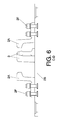
Figure 6 shows a section of the acute common crossing with movable point depicted inFigure 3 according to section lines CD. -
Figure 7 shows a section of the acute common crossing with movable point depicted inFigure 3 according to section lines EF. -
Figure 8 shows a section of the acute common crossing with movable point depicted inFigure 3 according to section lines GH. -
Figure 9 shows a section of the acute common crossing with movable point depicted inFigure 3 according to section lines IJ. - The crossing with moveable point (1) consists of two main elements, a fixed element (2) and another moveable element (3) or point. Said point (3) moves by manual or mechanical means, alternatively coupling inside the fixed element(2) to either side, giving way to the main line or the branch line of the turnout in which it is installed, forming a continuous rail track for the railway wheel. Additionally, the crossing with moveable point object of the invention (1) may comprise other elements, such as bearing plates, distance blocks, heel blocks, clips, etc.
- The front part of the fixed element (2) seen from the points of the switch, where contact with the wheels of the train occurs, is made up of a monolithic moulded part (2A) divided in two halves made of austenitic manganese steel, in contact with the railway wheels, a base (2B) made of a steel with a greater fatigue resistance than the austenitic manganese steel of the moulded part (2A), for example, carbon steel or low alloy steel, preferably rolled or forged, where it supports the moulded part (2A), entry rails (2C) preferably made of rolled carbon steel, and welded to the moulded part (2A) by means of a workshop welding process, and wing rails (2D) welded to the moulded part by means of a workshop welding process. Said wing rails (2D) can be made in a rail section or in sections of another type, and their purpose consists of serving as attachment for the fixed element (2) with the moveable element (3) in the heel or rear part of the crossing through the heel blocks (4) and serving as a support for other elements forming the crossing, such as distance blocks (5), slide plates (6), and ribbed heel base plates (7).
- The moulded part (2A) is attached to the base (2B) by means of bolted or riveted fasteners (2F), such that both (2A, 2B) are integral during their service life. The number, size and design of said bolted or riveted fasteners (2F) are expected to be such that the attachment between the moulded part (2A) and the base (2B) is at all times integral and clearances or breaks due to fatigue are not generated throughout the service life of the crossing.
- The base (2B) extends at least the entire length of the moulded part (2A) such that its manner of working under the passage of railway wheels essentially consists of pulsating tensile stresses. There are no discontinuities of the plate or base (2B) in the longitudinal direction of the moulded part (2A), given that this would create pulsating stress peaks in the front part of said moulded part (2A), which would lead to its premature fatigue failure. Said base (2B) therefore is continuous in the longitudinal direction of the crossing. By combining the suitable thickness in the base element (2B) with the height of the moulded part (2A) the pulsating tensile stresses in the lower part of the moulded part (2A) under the passage of the wheels are very small, and therefore, the life with respect to fatigue of the moulded part (2A) can be considerably increased, this being clearly greater than the life of said crossing taking into account only the wear which the railway wheels confer on their running surfaces.
- Since the base (2B) is be made of a material with a high fatigue threshold, it is sized such that its life is infinite with respect to the fatigue phenomenon with respect to the level of pulsating tensile stresses caused by the passage of the wheel.
- The upper part of the base (2B) likewise serves as a support and sliding element of the point or moveable element (3), which slides on said base in its lateral setting to alternatively couple to either side of the fixed element, and to thus give way to the main line and to the branch line. In said upper part, the base (2B) can bear surface treatments based on solid lubricants for the purpose of preventing the periodic lubrication.
- Additionally, the base (2B) can be supported on a set of metal plates (8) which also rest on the sleepers or the concrete slab of the infrastructure under the crossing with movable point, or the base (2B) can be directly assembled on said sleepers or said concrete slab without the interposition of metal plates or only with the interposition of resilient pads. In either case, the primary function of the base (2B) is to bear the pulsating tensile stresses caused under the passage of the wheels of the train units, and the secondary function is to serve as a support and slip surface for the point or moveable element (3) in its lateral setting.
- The point or moveable element (3) can have different types of construction, being made up of rails, forged pieces and even moulded elements made of austenitic manganese steel.
Claims (4)
- Acute common crossing with moveable point for railway turnouts, comprising a fixed element (2) and a moveable element (3), as well as wing rails (2D), heel blocks (4), distance blocks (5), slide chairs (6) and ribbed heel base plates (7),
characterised in that
the front part of the fixed element (2) seen from the points of the switch, where the contact with the railway wheels occurs, comprises a moulded part (2A) made of austenitic manganese steel and a base plate (2B), located below the moulded part, made of a steel with a greater fatigue resistance than the austenitic manganese steel of the moulded part (2A), for example, carbon steel or low alloy steel,
in that
the base plate (2B) is continuous and extends at least the entire length of the moulded part (2A),
and in that
the moulded part (2A) and the base plate (2B) are fixed to one another by fastening means, for example, by means of bolts or rivets (2F). - Acute common crossing with moveable point for turnouts according to claim 1, characterised in that the moveable element (3) slides in its setting on the base plate (2B) such that it alternatively couples to either side of the fixed element (2), giving way to the main line or the branch line and forming a continuous rail track.
- Acute common crossing with moveable point for turnouts according to any of claims 1 and 2, characterised in that the base plate (2B) of the fixed element (2) is supported on the infrastructure without the interposition of metal support plates.
- Acute common crossing with moveable point for railway turnouts according to any of claims 1 and 2, characterised in that the base plate (2B) of the fixed element (2) is supported on the infrastructure by means of the interposition of metal support plates (8).
Priority Applications (2)
| Application Number | Priority Date | Filing Date | Title |
|---|---|---|---|
| ES11382025.2T ES2488765T3 (en) | 2011-02-08 | 2011-02-08 | Sharp heart of movable rail tip |
| EP20110382025 EP2487293B1 (en) | 2011-02-08 | 2011-02-08 | Acute swing nose crossing for railways |
Applications Claiming Priority (1)
| Application Number | Priority Date | Filing Date | Title |
|---|---|---|---|
| EP20110382025 EP2487293B1 (en) | 2011-02-08 | 2011-02-08 | Acute swing nose crossing for railways |
Publications (2)
| Publication Number | Publication Date |
|---|---|
| EP2487293A1 true EP2487293A1 (en) | 2012-08-15 |
| EP2487293B1 EP2487293B1 (en) | 2014-05-07 |
Family
ID=44227765
Family Applications (1)
| Application Number | Title | Priority Date | Filing Date |
|---|---|---|---|
| EP20110382025 Active EP2487293B1 (en) | 2011-02-08 | 2011-02-08 | Acute swing nose crossing for railways |
Country Status (2)
| Country | Link |
|---|---|
| EP (1) | EP2487293B1 (en) |
| ES (1) | ES2488765T3 (en) |
Cited By (3)
| Publication number | Priority date | Publication date | Assignee | Title |
|---|---|---|---|---|
| CN103741565A (en) * | 2014-01-21 | 2014-04-23 | 唐山金山腾宇科技有限公司 | Waste alloy steel frog repairing process |
| KR20190047424A (en) * | 2017-10-27 | 2019-05-08 | 삼표레일웨이 주식회사 | Railroad crossing craddle with reinforcement unit |
| EP3696285A1 (en) * | 2019-02-15 | 2020-08-19 | Progress Rail Services UK Limited | Improved steel railway crossing |
Citations (5)
| Publication number | Priority date | Publication date | Assignee | Title |
|---|---|---|---|---|
| EP0343150A2 (en) * | 1988-05-20 | 1989-11-23 | VOEST-ALPINE Eisenbahnsysteme Gesellschaft m.b.H. | Switch including a frog comprising a principal and a secondary movable tongue |
| FR2640294A1 (en) | 1988-12-12 | 1990-06-15 | Cogifer Cie Gle Installat Ferr | Method for manufacturing a crossing (diamond, frog) with moving point and crossing (diamond, frog) thus obtained |
| FR2695662A1 (en) | 1992-09-11 | 1994-03-18 | Cogifer | Embedding the movable tip in the cradle of a crossover heart incorporated in the long welded rails and method of making such a fitting. |
| EP0838552A1 (en) | 1996-04-29 | 1998-04-29 | Jez Sistemas Ferroviarios, S.l. | Acute crossing of railway tongue |
| DE202004016709U1 (en) * | 2004-07-07 | 2005-02-03 | Thyssenkrupp Weichenbau Gmbh | Railway line cast crossover block has a detent with a block insert of hard wearing material |
-
2011
- 2011-02-08 EP EP20110382025 patent/EP2487293B1/en active Active
- 2011-02-08 ES ES11382025.2T patent/ES2488765T3/en active Active
Patent Citations (5)
| Publication number | Priority date | Publication date | Assignee | Title |
|---|---|---|---|---|
| EP0343150A2 (en) * | 1988-05-20 | 1989-11-23 | VOEST-ALPINE Eisenbahnsysteme Gesellschaft m.b.H. | Switch including a frog comprising a principal and a secondary movable tongue |
| FR2640294A1 (en) | 1988-12-12 | 1990-06-15 | Cogifer Cie Gle Installat Ferr | Method for manufacturing a crossing (diamond, frog) with moving point and crossing (diamond, frog) thus obtained |
| FR2695662A1 (en) | 1992-09-11 | 1994-03-18 | Cogifer | Embedding the movable tip in the cradle of a crossover heart incorporated in the long welded rails and method of making such a fitting. |
| EP0838552A1 (en) | 1996-04-29 | 1998-04-29 | Jez Sistemas Ferroviarios, S.l. | Acute crossing of railway tongue |
| DE202004016709U1 (en) * | 2004-07-07 | 2005-02-03 | Thyssenkrupp Weichenbau Gmbh | Railway line cast crossover block has a detent with a block insert of hard wearing material |
Cited By (4)
| Publication number | Priority date | Publication date | Assignee | Title |
|---|---|---|---|---|
| CN103741565A (en) * | 2014-01-21 | 2014-04-23 | 唐山金山腾宇科技有限公司 | Waste alloy steel frog repairing process |
| CN103741565B (en) * | 2014-01-21 | 2015-12-09 | 唐山金山腾宇科技有限公司 | The renovation technique of waste alloy steel frog |
| KR20190047424A (en) * | 2017-10-27 | 2019-05-08 | 삼표레일웨이 주식회사 | Railroad crossing craddle with reinforcement unit |
| EP3696285A1 (en) * | 2019-02-15 | 2020-08-19 | Progress Rail Services UK Limited | Improved steel railway crossing |
Also Published As
| Publication number | Publication date |
|---|---|
| EP2487293B1 (en) | 2014-05-07 |
| ES2488765T3 (en) | 2014-08-28 |
Similar Documents
| Publication | Publication Date | Title |
|---|---|---|
| JP5659965B2 (en) | Flash butt welding method for rail steel | |
| EP2487293B1 (en) | Acute swing nose crossing for railways | |
| Popović et al. | Managing rail service life | |
| US9206556B2 (en) | Elevated frog and rail crossing track assembly | |
| Kaewunruen | Effectiveness of using elastomeric pads to mitigate impact vibration at an urban turnout crossing | |
| AU2009216933B2 (en) | Rail steel with an excellent combination of wear properties and rolling contact fatigue resistance | |
| EP0838552B1 (en) | Points for a railway line | |
| US20150028165A1 (en) | Steel for producing parts for railway, railway crossings and switches and method for producing said parts | |
| RU2592178C1 (en) | Track of rectilinear high-speed railway | |
| Tomičić-Torlaković | Guidelines for the rail grade selection | |
| CN102747299A (en) | High-performance bainite abrasion resistant steel for railway frog in alpine region and manufacture method | |
| US1640204A (en) | Railroad switching device | |
| CN101492902A (en) | Heavy duty movable-point frog | |
| WO2010023675A1 (en) | Rail expansion joint | |
| EP1555347B1 (en) | Railway point with flexible tongue | |
| Stone et al. | Rail Steels: Developments Processing and Use | |
| RU2368717C2 (en) | Method for manufacturing of pointwork tongues | |
| EP2240642B1 (en) | Swing nose crossing | |
| RU2663759C2 (en) | Rail connection method | |
| CN110670423A (en) | Connecting device for concrete switch tie for metallurgical enterprise railway | |
| CN211498295U (en) | Improved I-shaped welded type wear-resistant guard rail for railway turnout | |
| Railway | TRACK STRUCTURE | |
| Frederick | Future rail requirements | |
| CN211036568U (en) | Concrete switch tie connecting assembly for railway of metallurgical enterprise | |
| RU75857U1 (en) | SLEEPER |
Legal Events
| Date | Code | Title | Description |
|---|---|---|---|
| PUAI | Public reference made under article 153(3) epc to a published international application that has entered the european phase |
Free format text: ORIGINAL CODE: 0009012 |
|
| AK | Designated contracting states |
Kind code of ref document: A1 Designated state(s): AL AT BE BG CH CY CZ DE DK EE ES FI FR GB GR HR HU IE IS IT LI LT LU LV MC MK MT NL NO PL PT RO RS SE SI SK SM TR |
|
| AX | Request for extension of the european patent |
Extension state: BA ME |
|
| 17P | Request for examination filed |
Effective date: 20130215 |
|
| GRAP | Despatch of communication of intention to grant a patent |
Free format text: ORIGINAL CODE: EPIDOSNIGR1 |
|
| INTG | Intention to grant announced |
Effective date: 20131128 |
|
| GRAS | Grant fee paid |
Free format text: ORIGINAL CODE: EPIDOSNIGR3 |
|
| GRAA | (expected) grant |
Free format text: ORIGINAL CODE: 0009210 |
|
| AK | Designated contracting states |
Kind code of ref document: B1 Designated state(s): AL AT BE BG CH CY CZ DE DK EE ES FI FR GB GR HR HU IE IS IT LI LT LU LV MC MK MT NL NO PL PT RO RS SE SI SK SM TR |
|
| REG | Reference to a national code |
Ref country code: GB Ref legal event code: FG4D |
|
| REG | Reference to a national code |
Ref country code: AT Ref legal event code: REF Ref document number: 666820 Country of ref document: AT Kind code of ref document: T Effective date: 20140515 |
|
| REG | Reference to a national code |
Ref country code: IE Ref legal event code: FG4D |
|
| REG | Reference to a national code |
Ref country code: DE Ref legal event code: R096 Ref document number: 602011006771 Country of ref document: DE Effective date: 20140618 |
|
| REG | Reference to a national code |
Ref country code: ES Ref legal event code: FG2A Ref document number: 2488765 Country of ref document: ES Kind code of ref document: T3 Effective date: 20140828 |
|
| REG | Reference to a national code |
Ref country code: AT Ref legal event code: MK05 Ref document number: 666820 Country of ref document: AT Kind code of ref document: T Effective date: 20140507 |
|
| REG | Reference to a national code |
Ref country code: NL Ref legal event code: VDEP Effective date: 20140507 |
|
| REG | Reference to a national code |
Ref country code: LT Ref legal event code: MG4D |
|
| PG25 | Lapsed in a contracting state [announced via postgrant information from national office to epo] |
Ref country code: IS Free format text: LAPSE BECAUSE OF FAILURE TO SUBMIT A TRANSLATION OF THE DESCRIPTION OR TO PAY THE FEE WITHIN THE PRESCRIBED TIME-LIMIT Effective date: 20140907 Ref country code: CY Free format text: LAPSE BECAUSE OF FAILURE TO SUBMIT A TRANSLATION OF THE DESCRIPTION OR TO PAY THE FEE WITHIN THE PRESCRIBED TIME-LIMIT Effective date: 20140507 Ref country code: LT Free format text: LAPSE BECAUSE OF FAILURE TO SUBMIT A TRANSLATION OF THE DESCRIPTION OR TO PAY THE FEE WITHIN THE PRESCRIBED TIME-LIMIT Effective date: 20140507 Ref country code: FI Free format text: LAPSE BECAUSE OF FAILURE TO SUBMIT A TRANSLATION OF THE DESCRIPTION OR TO PAY THE FEE WITHIN THE PRESCRIBED TIME-LIMIT Effective date: 20140507 Ref country code: GR Free format text: LAPSE BECAUSE OF FAILURE TO SUBMIT A TRANSLATION OF THE DESCRIPTION OR TO PAY THE FEE WITHIN THE PRESCRIBED TIME-LIMIT Effective date: 20140808 Ref country code: NO Free format text: LAPSE BECAUSE OF FAILURE TO SUBMIT A TRANSLATION OF THE DESCRIPTION OR TO PAY THE FEE WITHIN THE PRESCRIBED TIME-LIMIT Effective date: 20140807 |
|
| PG25 | Lapsed in a contracting state [announced via postgrant information from national office to epo] |
Ref country code: AT Free format text: LAPSE BECAUSE OF FAILURE TO SUBMIT A TRANSLATION OF THE DESCRIPTION OR TO PAY THE FEE WITHIN THE PRESCRIBED TIME-LIMIT Effective date: 20140507 Ref country code: RS Free format text: LAPSE BECAUSE OF FAILURE TO SUBMIT A TRANSLATION OF THE DESCRIPTION OR TO PAY THE FEE WITHIN THE PRESCRIBED TIME-LIMIT Effective date: 20140507 Ref country code: PL Free format text: LAPSE BECAUSE OF FAILURE TO SUBMIT A TRANSLATION OF THE DESCRIPTION OR TO PAY THE FEE WITHIN THE PRESCRIBED TIME-LIMIT Effective date: 20140507 Ref country code: LV Free format text: LAPSE BECAUSE OF FAILURE TO SUBMIT A TRANSLATION OF THE DESCRIPTION OR TO PAY THE FEE WITHIN THE PRESCRIBED TIME-LIMIT Effective date: 20140507 Ref country code: HR Free format text: LAPSE BECAUSE OF FAILURE TO SUBMIT A TRANSLATION OF THE DESCRIPTION OR TO PAY THE FEE WITHIN THE PRESCRIBED TIME-LIMIT Effective date: 20140507 Ref country code: SE Free format text: LAPSE BECAUSE OF FAILURE TO SUBMIT A TRANSLATION OF THE DESCRIPTION OR TO PAY THE FEE WITHIN THE PRESCRIBED TIME-LIMIT Effective date: 20140507 |
|
| PG25 | Lapsed in a contracting state [announced via postgrant information from national office to epo] |
Ref country code: PT Free format text: LAPSE BECAUSE OF FAILURE TO SUBMIT A TRANSLATION OF THE DESCRIPTION OR TO PAY THE FEE WITHIN THE PRESCRIBED TIME-LIMIT Effective date: 20140908 |
|
| PG25 | Lapsed in a contracting state [announced via postgrant information from national office to epo] |
Ref country code: CZ Free format text: LAPSE BECAUSE OF FAILURE TO SUBMIT A TRANSLATION OF THE DESCRIPTION OR TO PAY THE FEE WITHIN THE PRESCRIBED TIME-LIMIT Effective date: 20140507 Ref country code: BE Free format text: LAPSE BECAUSE OF FAILURE TO SUBMIT A TRANSLATION OF THE DESCRIPTION OR TO PAY THE FEE WITHIN THE PRESCRIBED TIME-LIMIT Effective date: 20140507 Ref country code: EE Free format text: LAPSE BECAUSE OF FAILURE TO SUBMIT A TRANSLATION OF THE DESCRIPTION OR TO PAY THE FEE WITHIN THE PRESCRIBED TIME-LIMIT Effective date: 20140507 Ref country code: DK Free format text: LAPSE BECAUSE OF FAILURE TO SUBMIT A TRANSLATION OF THE DESCRIPTION OR TO PAY THE FEE WITHIN THE PRESCRIBED TIME-LIMIT Effective date: 20140507 Ref country code: RO Free format text: LAPSE BECAUSE OF FAILURE TO SUBMIT A TRANSLATION OF THE DESCRIPTION OR TO PAY THE FEE WITHIN THE PRESCRIBED TIME-LIMIT Effective date: 20140507 Ref country code: SK Free format text: LAPSE BECAUSE OF FAILURE TO SUBMIT A TRANSLATION OF THE DESCRIPTION OR TO PAY THE FEE WITHIN THE PRESCRIBED TIME-LIMIT Effective date: 20140507 |
|
| REG | Reference to a national code |
Ref country code: DE Ref legal event code: R097 Ref document number: 602011006771 Country of ref document: DE |
|
| PG25 | Lapsed in a contracting state [announced via postgrant information from national office to epo] |
Ref country code: NL Free format text: LAPSE BECAUSE OF FAILURE TO SUBMIT A TRANSLATION OF THE DESCRIPTION OR TO PAY THE FEE WITHIN THE PRESCRIBED TIME-LIMIT Effective date: 20140507 |
|
| PLBE | No opposition filed within time limit |
Free format text: ORIGINAL CODE: 0009261 |
|
| STAA | Information on the status of an ep patent application or granted ep patent |
Free format text: STATUS: NO OPPOSITION FILED WITHIN TIME LIMIT |
|
| 26N | No opposition filed |
Effective date: 20150210 |
|
| PG25 | Lapsed in a contracting state [announced via postgrant information from national office to epo] |
Ref country code: IT Free format text: LAPSE BECAUSE OF FAILURE TO SUBMIT A TRANSLATION OF THE DESCRIPTION OR TO PAY THE FEE WITHIN THE PRESCRIBED TIME-LIMIT Effective date: 20140507 |
|
| REG | Reference to a national code |
Ref country code: DE Ref legal event code: R097 Ref document number: 602011006771 Country of ref document: DE Effective date: 20150210 |
|
| PG25 | Lapsed in a contracting state [announced via postgrant information from national office to epo] |
Ref country code: SI Free format text: LAPSE BECAUSE OF FAILURE TO SUBMIT A TRANSLATION OF THE DESCRIPTION OR TO PAY THE FEE WITHIN THE PRESCRIBED TIME-LIMIT Effective date: 20140507 |
|
| REG | Reference to a national code |
Ref country code: DE Ref legal event code: R119 Ref document number: 602011006771 Country of ref document: DE |
|
| PG25 | Lapsed in a contracting state [announced via postgrant information from national office to epo] |
Ref country code: LU Free format text: LAPSE BECAUSE OF FAILURE TO SUBMIT A TRANSLATION OF THE DESCRIPTION OR TO PAY THE FEE WITHIN THE PRESCRIBED TIME-LIMIT Effective date: 20150208 |
|
| REG | Reference to a national code |
Ref country code: CH Ref legal event code: PL |
|
| GBPC | Gb: european patent ceased through non-payment of renewal fee |
Effective date: 20150208 |
|
| PG25 | Lapsed in a contracting state [announced via postgrant information from national office to epo] |
Ref country code: CH Free format text: LAPSE BECAUSE OF NON-PAYMENT OF DUE FEES Effective date: 20150228 Ref country code: MC Free format text: LAPSE BECAUSE OF FAILURE TO SUBMIT A TRANSLATION OF THE DESCRIPTION OR TO PAY THE FEE WITHIN THE PRESCRIBED TIME-LIMIT Effective date: 20140507 Ref country code: LI Free format text: LAPSE BECAUSE OF NON-PAYMENT OF DUE FEES Effective date: 20150228 |
|
| REG | Reference to a national code |
Ref country code: IE Ref legal event code: MM4A |
|
| REG | Reference to a national code |
Ref country code: FR Ref legal event code: ST Effective date: 20151030 |
|
| PG25 | Lapsed in a contracting state [announced via postgrant information from national office to epo] |
Ref country code: GB Free format text: LAPSE BECAUSE OF NON-PAYMENT OF DUE FEES Effective date: 20150208 Ref country code: DE Free format text: LAPSE BECAUSE OF NON-PAYMENT OF DUE FEES Effective date: 20150901 Ref country code: IE Free format text: LAPSE BECAUSE OF NON-PAYMENT OF DUE FEES Effective date: 20150208 |
|
| PG25 | Lapsed in a contracting state [announced via postgrant information from national office to epo] |
Ref country code: FR Free format text: LAPSE BECAUSE OF NON-PAYMENT OF DUE FEES Effective date: 20150302 |
|
| PG25 | Lapsed in a contracting state [announced via postgrant information from national office to epo] |
Ref country code: MT Free format text: LAPSE BECAUSE OF FAILURE TO SUBMIT A TRANSLATION OF THE DESCRIPTION OR TO PAY THE FEE WITHIN THE PRESCRIBED TIME-LIMIT Effective date: 20140507 |
|
| PG25 | Lapsed in a contracting state [announced via postgrant information from national office to epo] |
Ref country code: HU Free format text: LAPSE BECAUSE OF FAILURE TO SUBMIT A TRANSLATION OF THE DESCRIPTION OR TO PAY THE FEE WITHIN THE PRESCRIBED TIME-LIMIT; INVALID AB INITIO Effective date: 20110208 Ref country code: SM Free format text: LAPSE BECAUSE OF FAILURE TO SUBMIT A TRANSLATION OF THE DESCRIPTION OR TO PAY THE FEE WITHIN THE PRESCRIBED TIME-LIMIT Effective date: 20140507 Ref country code: BG Free format text: LAPSE BECAUSE OF FAILURE TO SUBMIT A TRANSLATION OF THE DESCRIPTION OR TO PAY THE FEE WITHIN THE PRESCRIBED TIME-LIMIT Effective date: 20140507 |
|
| PG25 | Lapsed in a contracting state [announced via postgrant information from national office to epo] |
Ref country code: TR Free format text: LAPSE BECAUSE OF FAILURE TO SUBMIT A TRANSLATION OF THE DESCRIPTION OR TO PAY THE FEE WITHIN THE PRESCRIBED TIME-LIMIT Effective date: 20140507 |
|
| PG25 | Lapsed in a contracting state [announced via postgrant information from national office to epo] |
Ref country code: MK Free format text: LAPSE BECAUSE OF FAILURE TO SUBMIT A TRANSLATION OF THE DESCRIPTION OR TO PAY THE FEE WITHIN THE PRESCRIBED TIME-LIMIT Effective date: 20140507 |
|
| PG25 | Lapsed in a contracting state [announced via postgrant information from national office to epo] |
Ref country code: AL Free format text: LAPSE BECAUSE OF FAILURE TO SUBMIT A TRANSLATION OF THE DESCRIPTION OR TO PAY THE FEE WITHIN THE PRESCRIBED TIME-LIMIT Effective date: 20140507 |
|
| PGFP | Annual fee paid to national office [announced via postgrant information from national office to epo] |
Ref country code: ES Payment date: 20240325 Year of fee payment: 14 |