EP2487018B1 - Vented mold and method for producing molded article - Google Patents
Vented mold and method for producing molded article Download PDFInfo
- Publication number
- EP2487018B1 EP2487018B1 EP12166482.5A EP12166482A EP2487018B1 EP 2487018 B1 EP2487018 B1 EP 2487018B1 EP 12166482 A EP12166482 A EP 12166482A EP 2487018 B1 EP2487018 B1 EP 2487018B1
- Authority
- EP
- European Patent Office
- Prior art keywords
- mold
- foam
- vent
- vents
- grooves
- Prior art date
- Legal status (The legal status is an assumption and is not a legal conclusion. Google has not performed a legal analysis and makes no representation as to the accuracy of the status listed.)
- Active
Links
- 238000004519 manufacturing process Methods 0.000 title description 18
- 239000000203 mixture Substances 0.000 claims description 52
- 239000007788 liquid Substances 0.000 claims description 25
- 229920002635 polyurethane Polymers 0.000 claims description 20
- 239000004814 polyurethane Substances 0.000 claims description 20
- 238000000034 method Methods 0.000 claims description 12
- 229920005830 Polyurethane Foam Polymers 0.000 claims description 8
- 239000011496 polyurethane foam Substances 0.000 claims description 8
- 230000008569 process Effects 0.000 claims description 6
- 239000012530 fluid Substances 0.000 claims 1
- 239000006260 foam Substances 0.000 description 107
- 239000007789 gas Substances 0.000 description 32
- 238000013022 venting Methods 0.000 description 21
- 239000000047 product Substances 0.000 description 14
- 239000000463 material Substances 0.000 description 13
- 238000013459 approach Methods 0.000 description 12
- 230000002093 peripheral effect Effects 0.000 description 11
- 230000000295 complement effect Effects 0.000 description 9
- 230000007547 defect Effects 0.000 description 6
- 238000005187 foaming Methods 0.000 description 6
- 238000000465 moulding Methods 0.000 description 6
- 230000008901 benefit Effects 0.000 description 5
- 238000006116 polymerization reaction Methods 0.000 description 5
- 235000001674 Agaricus brunnescens Nutrition 0.000 description 4
- 238000013461 design Methods 0.000 description 4
- 230000000694 effects Effects 0.000 description 4
- 235000012771 pancakes Nutrition 0.000 description 4
- 238000006243 chemical reaction Methods 0.000 description 3
- 230000004048 modification Effects 0.000 description 3
- 238000012986 modification Methods 0.000 description 3
- 239000002994 raw material Substances 0.000 description 3
- 239000011800 void material Substances 0.000 description 3
- 230000015572 biosynthetic process Effects 0.000 description 2
- 230000008859 change Effects 0.000 description 2
- 230000005465 channeling Effects 0.000 description 2
- 230000002950 deficient Effects 0.000 description 2
- 239000004744 fabric Substances 0.000 description 2
- 239000006261 foam material Substances 0.000 description 2
- 230000006872 improvement Effects 0.000 description 2
- 230000000116 mitigating effect Effects 0.000 description 2
- 239000006082 mold release agent Substances 0.000 description 2
- 230000000630 rising effect Effects 0.000 description 2
- PYADVBBPPYGPGF-UHFFFAOYSA-N 3,3-dimethylbutane-2,2-diamine Chemical compound CC(C)(C)C(C)(N)N PYADVBBPPYGPGF-UHFFFAOYSA-N 0.000 description 1
- UEEJHVSXFDXPFK-UHFFFAOYSA-N N-dimethylaminoethanol Chemical compound CN(C)CCO UEEJHVSXFDXPFK-UHFFFAOYSA-N 0.000 description 1
- 230000006978 adaptation Effects 0.000 description 1
- 230000000903 blocking effect Effects 0.000 description 1
- 239000003795 chemical substances by application Substances 0.000 description 1
- 238000004140 cleaning Methods 0.000 description 1
- 229960002887 deanol Drugs 0.000 description 1
- 238000000280 densification Methods 0.000 description 1
- 239000010432 diamond Substances 0.000 description 1
- 239000012972 dimethylethanolamine Substances 0.000 description 1
- 230000001747 exhibiting effect Effects 0.000 description 1
- 239000012467 final product Substances 0.000 description 1
- 238000009472 formulation Methods 0.000 description 1
- 239000000446 fuel Substances 0.000 description 1
- 238000009434 installation Methods 0.000 description 1
- 230000003993 interaction Effects 0.000 description 1
- 229920000126 latex Polymers 0.000 description 1
- 239000004816 latex Substances 0.000 description 1
- 239000010985 leather Substances 0.000 description 1
- 238000012423 maintenance Methods 0.000 description 1
- 239000013518 molded foam Substances 0.000 description 1
- 229920003052 natural elastomer Polymers 0.000 description 1
- 229920001194 natural rubber Polymers 0.000 description 1
- 230000003287 optical effect Effects 0.000 description 1
- 239000005056 polyisocyanate Substances 0.000 description 1
- 229920001228 polyisocyanate Polymers 0.000 description 1
- 229920000642 polymer Polymers 0.000 description 1
- 229920005862 polyol Polymers 0.000 description 1
- 150000003077 polyols Chemical class 0.000 description 1
- 230000009467 reduction Effects 0.000 description 1
- 230000004044 response Effects 0.000 description 1
- 238000007789 sealing Methods 0.000 description 1
- 238000004513 sizing Methods 0.000 description 1
- 229920003048 styrene butadiene rubber Polymers 0.000 description 1
- 239000000126 substance Substances 0.000 description 1
- 238000010408 sweeping Methods 0.000 description 1
- 208000024891 symptom Diseases 0.000 description 1
- 238000012360 testing method Methods 0.000 description 1
- 125000000391 vinyl group Chemical group [H]C([*])=C([H])[H] 0.000 description 1
- 229920002554 vinyl polymer Polymers 0.000 description 1
- XLYOFNOQVPJJNP-UHFFFAOYSA-N water Substances O XLYOFNOQVPJJNP-UHFFFAOYSA-N 0.000 description 1
Images


Classifications
-
- B—PERFORMING OPERATIONS; TRANSPORTING
- B29—WORKING OF PLASTICS; WORKING OF SUBSTANCES IN A PLASTIC STATE IN GENERAL
- B29C—SHAPING OR JOINING OF PLASTICS; SHAPING OF MATERIAL IN A PLASTIC STATE, NOT OTHERWISE PROVIDED FOR; AFTER-TREATMENT OF THE SHAPED PRODUCTS, e.g. REPAIRING
- B29C33/00—Moulds or cores; Details thereof or accessories therefor
- B29C33/10—Moulds or cores; Details thereof or accessories therefor with incorporated venting means
-
- B—PERFORMING OPERATIONS; TRANSPORTING
- B29—WORKING OF PLASTICS; WORKING OF SUBSTANCES IN A PLASTIC STATE IN GENERAL
- B29C—SHAPING OR JOINING OF PLASTICS; SHAPING OF MATERIAL IN A PLASTIC STATE, NOT OTHERWISE PROVIDED FOR; AFTER-TREATMENT OF THE SHAPED PRODUCTS, e.g. REPAIRING
- B29C44/00—Shaping by internal pressure generated in the material, e.g. swelling or foaming ; Producing porous or cellular expanded plastics articles
- B29C44/34—Auxiliary operations
- B29C44/58—Moulds
- B29C44/588—Moulds with means for venting, e.g. releasing foaming gas
-
- B—PERFORMING OPERATIONS; TRANSPORTING
- B29—WORKING OF PLASTICS; WORKING OF SUBSTANCES IN A PLASTIC STATE IN GENERAL
- B29C—SHAPING OR JOINING OF PLASTICS; SHAPING OF MATERIAL IN A PLASTIC STATE, NOT OTHERWISE PROVIDED FOR; AFTER-TREATMENT OF THE SHAPED PRODUCTS, e.g. REPAIRING
- B29C44/00—Shaping by internal pressure generated in the material, e.g. swelling or foaming ; Producing porous or cellular expanded plastics articles
- B29C44/34—Auxiliary operations
- B29C44/56—After-treatment of articles, e.g. for altering the shape
- B29C44/5609—Purging of residual gas, e.g. noxious or explosive blowing agents
-
- B—PERFORMING OPERATIONS; TRANSPORTING
- B29—WORKING OF PLASTICS; WORKING OF SUBSTANCES IN A PLASTIC STATE IN GENERAL
- B29K—INDEXING SCHEME ASSOCIATED WITH SUBCLASSES B29B, B29C OR B29D, RELATING TO MOULDING MATERIALS OR TO MATERIALS FOR MOULDS, REINFORCEMENTS, FILLERS OR PREFORMED PARTS, e.g. INSERTS
- B29K2075/00—Use of PU, i.e. polyureas or polyurethanes or derivatives thereof, as moulding material
-
- Y—GENERAL TAGGING OF NEW TECHNOLOGICAL DEVELOPMENTS; GENERAL TAGGING OF CROSS-SECTIONAL TECHNOLOGIES SPANNING OVER SEVERAL SECTIONS OF THE IPC; TECHNICAL SUBJECTS COVERED BY FORMER USPC CROSS-REFERENCE ART COLLECTIONS [XRACs] AND DIGESTS
- Y10—TECHNICAL SUBJECTS COVERED BY FORMER USPC
- Y10S—TECHNICAL SUBJECTS COVERED BY FORMER USPC CROSS-REFERENCE ART COLLECTIONS [XRACs] AND DIGESTS
- Y10S297/00—Chairs and seats
- Y10S297/01—Foam
-
- Y—GENERAL TAGGING OF NEW TECHNOLOGICAL DEVELOPMENTS; GENERAL TAGGING OF CROSS-SECTIONAL TECHNOLOGIES SPANNING OVER SEVERAL SECTIONS OF THE IPC; TECHNICAL SUBJECTS COVERED BY FORMER USPC CROSS-REFERENCE ART COLLECTIONS [XRACs] AND DIGESTS
- Y10—TECHNICAL SUBJECTS COVERED BY FORMER USPC
- Y10S—TECHNICAL SUBJECTS COVERED BY FORMER USPC CROSS-REFERENCE ART COLLECTIONS [XRACs] AND DIGESTS
- Y10S425/00—Plastic article or earthenware shaping or treating: apparatus
- Y10S425/812—Venting
Definitions
- the present invention relates to a vented mold and to a method for producing a molded article.
- polyurethane foams are somewhat unique in that foaming and at least a portion of the polymerization process occur simultaneously.
- a typical formulation comprises:
- the mixture is dispensed into a mold using a suitable mixing head, after which the mold is then closed to permit the expanding mass within it to be molded. Accordingly, it is convenient generally to refer to the mixture initially dispensed into the mold as "a liquid foamable polymeric composition" or, in this case, "a liquid foamable polyurethane composition". As the composition expands in the mold, polymerization occurs and the polymer so formed becomes solidified.
- a liquid foamable polymeric composition When molding a liquid foamable polymeric composition to form articles, such as polyurethane foam articles, it is conventional to use a clam-shell mold comprising a bottom mold and a top mold which, when closed, define a mold cavity.
- the mold is opened, the liquid foamable polyurethane composition is dispensed into the mold cavity and the mold is closed as a chemical reaction causes the composition to expand. After the mold is closed, the composition expands to fill the interior cavity of the mold.
- the composition may be dispensed into a closed mold. In either case, as the polymerization reaction is completed, the foam cures and permanently assumes the shape of the mold cavity.
- the mold be adequately vented to allow the air present in the mold to exit the mold as the foamable composition expands. Further, it is important to allow a portion of the gases (typically CO 2 in the production of polyurethane) generated during polymerization to exit the mold.
- gases typically CO 2 in the production of polyurethane
- first generation clam-shell molds have been designed with drilled or cut passages in the top mold to provide vents. Locating, sizing and deciding upon the number of these vents is a matter of some skill on the part of mold designer and the production engineers, and is often an iterative procedure with more vents being added to various locations or other vents being blocked-off after test runs have been made.
- Document WO-A-9922924 discloses a device for molding automotive cushion seats using a liquid foamable polyurethane composition.
- the mold has a plurality of vents having obstructions.
- the invention is defined by the combination of features of independent claim 1 and by a method in accordance with claim 4.
- the present inventors have discovered a new approach to improving venting of mold, particularly molds for production of foam articles.
- the approach is quite different from that used in the past.
- venting involved placement of a number of vents in areas of a mold where it was believed localized collection of gas would occur in the mold cavity.
- placement of vents was done in an iterative manner. Specifically, as foam parts were made and surface defects were seen, the response would be simply to place a vent (e.g., one or both of a so-called "autovent” and "ribbon vent” discussed below) in the area of the mold corresponding to the position of the defect on the resulting foam part.
- a vent e.g., one or both of a so-called “autovent” and “ribbon vent” discussed below
- the approach used by the present inventors is to de-emphasize location of a great number vents in potential areas of concern in the mold. Rather, the present inventors have discovered that the use of one or more grooves/slots in the mold cavity surface effectively acts as a siphon to draw gas away from the composition to be molded.
- the at least one groove and/or slot is connected to one or more vents which then allows for escape of the gas from the mold cavity to the exterior of the mold.
- the one or more grooves/slots are provided in a so-called network or grid-like orientation to cover a substantial portion of the surface of the mold cavity as a web (e.g., a substantial portion of the surface of the mold cavity corresponding to the B-surface of the finished part).
- a web e.g., a substantial portion of the surface of the mold cavity corresponding to the B-surface of the finished part.
- grooves/slots are active for siphoning or otherwise channeling gas (e.g., via a capillary effect) in the mold cavity as the internal pressure in the mold remains relatively low.
- the grooves and/or slots are connected to a vent which maybe a ribbon vent, an autovent or a so-called smart vent.
- the one or more grooves/slots disposed in a "high point" of the lid of the mold since this will facilitate drawing of the gas from the top of the geometric feature which is to be vented. It also highly preferred to orient a slot/groove on the periphery of the mold cavity near the parting line. This peripheral groove/slot can be disposed in the lid or the bowl of the mold and depends, in part, of the shape of the article being produced.
- grooves/slots are particularly applicable in a situation where the part to be molded is highly contoured.
- the groove/slot maybe disposed on the high point of a contour surface as discussed above and/or the tangent of radius of the edge or lip of a contour in the mold.
- connection grooves/slots to interconnect the peripheral groove/slot with, for example, a ribbon vent.
- the grid may not necessarily need to contain grooves/slots arranged to define precise squares.
- the part to be produced is somewhat elongate, it is preferred to run a number of grooves/slots lengthwise on the surface of the mold cavity and couple this with pour pattern generally at one end of the mold cavity.
- the foam composition By dispensing the foam composition at one end of the mold cavity, the foam needs to travel lengthwise to fill the mold cavity and this allows lengthwise orientation of the grooves/slots to run ahead of foam flow reliably moving gas from the mold cavity to the vent and out of the mold.
- groove/slots oriented in a manner whereby the groove/slots have redundant paths to a number of vents disposed in the lid and/or parting line of the mold.
- liquid foamable polymeric composition according to the invention is based upon polyurethane, which will be referred throughout this specification.
- a first generation prior art mold will first be discussed, with reference to Figures 1 and 2 , and a second generation prior art mold will then be discussed, with reference to Figures 3 and 4 .
- Mold 20 includes a lower mold 24 (also known in the art as a "bowl”) and an upper mold 28 (also known in the art as a “lid”) which are joined by a conventional hinge or other means (not shown).
- upper mold 28 is released from lower mold 24 and a pre-determined amount of liquid foamable polyurethane composition is dispensed into lower mold 24.
- Upper mold 28 and lower mold 24 are closed and engaged to seal the mold, and the liquid foamable polyurethane composition expands, displacing the air within cavity 32.
- This displaced air exits cavity 32 through a relatively large parting line vent 36 and through one or more top vent passages 38 in upper mold 28.
- polyurethane composition expands, polymerization of the composition occurs along with the evolution of gaseous CO 2 in cavity 32.
- This gaseous CO 2 may also exit cavity 32 through parting line 36 and through top vent passages 38.
- the liquid foamable polymeric composition eventually completely polymerizes and cures, acquiring the shape of cavity 32.
- the amount of liquid foamable polyurethane composition dispensed in cavity 32 must be selected to ensure that cavity 32 will be substantially completely filled, in order to avoid the occurrence of underfill-associate foam collapse, voids and other foaming defects in the molded article. While the determination of the proper amount of liquid foamable polyurethane composition for a particular mold may generally be calculated, when using a first generation mold such as mold 20, it has been required to dispense an excess amount of polymeric composition into the mold to compensate for material which moves through and exits parting line vent 36 and top vent passages 38.
- any further expansion of the foam results in movement of the foam into parting line vent 36 and/or top vent passages 38.
- the foam reaches the level of the parting line vent and/or the vent passages at approximately the same time, which usually occurs at or near the maximum expansion point of the foam.
- the foam in the cavity typically reaches the level of the parting line vents and/or different vent passages at different times while the foam is still expanding. For example, in a region wherein the top of cavity 32 is lower than surrounding regions, such as indicated at 40 in Figure 1 , the foam may quickly reach the top vent passages 38. As the foam is still rising in the rest of cavity 32 and has not yet cured, a relatively significant amount of foam may enter top vent passages 38 in this region.
- the amount of foam which enters parting line vents 36 and top vent passages 38 reduces the amount of foam remaining in cavity 32 by a like amount, it is necessary that the amount of liquid foamable polyurethane composition placed in cavity 32 include an amount in excess of that required to fill cavity 32 to offset the foam which entered the parting line and vents. This excess amount, while necessary for proper operation of the prior art mold, is essentially wasted material which must be laboriously removed in a further post-production step and thus adds to the cost of forming the article.
- the foam which enters top vent passages 38 forms "mushrooms” 54 (shown in ghosted line) of wasted material on the molded article 50.
- the material which enters parting line vents 36 forms "pancakes" 55 of wasted material on the molded article 50.
- mushrooms 54 and pancakes 55 must be disconnected from article 50 and removed from the mold 20 prior to application of a finish cover to ensure a finished covered article which is of acceptable appearance and texture, and to prepare mold 20 for re-use. The necessity of removing mushrooms 54 and pancakes 55 results in an increased labour cost associated with manufacturing the molded product.
- excess liquid foamable polyurethane composition which is added to offset the material extruded into the vents
- excess liquid foamable polyurethane composition is also added to compensate for process variations due to changes in temperature, humidity, ambient pressure and minor changes in the composition of the liquid foamable polyurethane composition. Accordingly, in these first generation prior art molds, the wastage of material exiting the vents is inevitable.
- Top vent system 60 comprises a cylindrical bore 62 and a relief pin 64 disposed within cylindrical bore 62.
- the exterior of cylindrical bore 62 comprises a threaded portion 66 which engages a complementary threaded portion of the mold (not shown).
- the portion of relief pin 64 nearest the opening of cylindrical bore 62 is hexagonal in cross-section.
- the six points of the hexagonal cross-section of relief pin 64 are in engagement with cylindrical bore 62 and define six segment-shaped vent passages 68.
- the proximal end (not shown) of relief pin 64 comprises a cross-section complementary to cylindrical bore 62.
- An opening (not shown) is provided between the distal end and the proximal end (not shown) of relief pin 64 to allow gases entering vent passages 68 to exit top vent system 60.
- Top vent system 60 is incorporated in a mold such as mold 20 ( Figure 1 ) where it would replace each of vent passages 38.
- liquid foamable polyurethane composition is dispensed into cavity 32, and lower mold 24 and upper mold 28 are sealingly engaged.
- the air in cavity 32 and the gases produced by the chemical reaction occurring in the expanding composition are vented through vent passages 68.
- the viscosity of these gases are such that they flow relatively easily through vent passages 68.
- the foam enters vent passages 68. Due to the presentation of a restriction by vent passages 68 to the expanding composition, the latter can only move slowly through vent passages 68.
- the liquid foamable polymeric composition will stop moving therein before it travels a significant distance along the vents and before it the exit opening (not shown) of top vent system 60.
- the foam article produced is demolded from mold 20. This is achieved by opening lower mold 24 and upper mold 28 and removing the foam article from lower mold 24. During mold opening, any foam material which has expanded in vent passages 68 will be torn from the foam article. Such torn material results in blockage of vent passages 68 and thus, must be removed prior to reuse of mold 20.
- mold 100 comprises a lid 105 and bowl 110 which is realisably engageable with lid 105.
- Lid 105 includes a series of parting line or so-called “ribbon vents" disposed therein.
- lid 105 Also disposed in lid 105 are a series of so-called auto vents 120 similar to those taught by the Clark et. al patents.
- a foamable composition (not shown) is disposed in bowl 110 via a dispenser 125. Lid 105 is then closed and the flowing mass is allowed to fill the mold cavity. Thereafter, lid 105 is swung open and a foam part 130 is removed from mold 100.
- Foam part 130 comprises a series of foam ribbons 135 which need not be trimmed and can simply be folded back during application of a trim cover to form part 130.
- voids there are two defects which are seen from time to time: voids and underfill.
- Underfill is a surface phenomenon which manifests itself in foam product 130 in the form of surface cavities 140.
- voids 145 within foam element 130 (“subsurface voids") and on the surface of foam element 130 (not shown - "surface voids") is another problem.
- Surface voids tend to be manifested in the foam product as a localized area of the foam part that has not been formed - e.g., the foam composition does not expand to completely occupy a highly contoured section of the mold lid such that the resulting foam part is missing a section corresponding to the void.
- lid 105 is used to mold the so-called B-surface of the foam part whereas the surface of bowl 110 is used is use to mold the so-called A-surface of foam part 130.
- surface cavities 140 can occur on any surface of foam element 130, they can be regularly present under the B-surface of foam element 130. It has been conventional in the art to respond to observation of underfill surface cavities 140 by placement of another autovent 120 in the area of lid 105 corresponding to the location of void 140.
- the present inventors have adapted a completely different approach to improving venting of gas formed as the foaming mass fills the mold cavity.
- the present inventors have discovered that it is not necessary to have such a large number of vents nor is it necessary to rely on such vents for venting a localized portion of the mold cavity.
- one or more grooves (or slots) in the surface of the mold cavity can be used as a conduit to funnel, draw, siphon, etc. gas to be vented to a conventional vent without the need to place a vent in each area where gas is expected to be vented.
- these grooves or slots are disposed in a intersecting or a grid-like fashion combined with provision of at least one such groove/slot in the periphery of the mold cavity.
- These groove/slot function as siphons (e.g. via a capillary effect) to facilitate removal of gas from the mold cavity.
- the venting approach in the present mold relates to use of previous local vents as effective area vents by disposing a plurality of grooves/slots in the mold cavity surface.
- the capacity of these grooves/slots to transport gas effectively is a function of the interaction with the natural growth of the rising foam, the thickness of the area in which the grooves/slots are contained and the obstruction effect of the geometries in the path to the vents.
- the grooves-slots are effective for channeling gas to be vented to a vent.
- a mold 200 comprising a lid 205 and a bowl 210 which are releasably engageable in a manner similar to that described above with respect to mold 100.
- Four vents 220 are disposed in lid 205.
- a network 225 of grooves is also disposed in lid 205. Network 225 extends to a peripheral portion 230 of the mold cavity.
- network 225 is connected to vents 220.
- composition 235 expands in the direction of arrows A.
- gas is produced and the pressure in mold cavity increases.
- the grooves/slots in network 225 are effectively disposed ahead of foam flow and are reliable to channel or funnel gas toward vents 220 even though vents 220 are not disposed throughout the entire surface of lid 205.
- the drawing out of gasses produced during expansion is facilitated by placement of vents 220 at or near the peak of the contours in lid 205.
- foam part 240 is shown in Figure 10 .
- foam part 240 can be produced with virtually no underfill or voiding.
- foam part 240 comprises a "negative" of network 225 on the B-surface thereof in the form of a network 245 of foam ridge.
- foam part 240 is completely trim-free and can be sent to trim cover operations without the need to remove flash or other excess materials.
- FIG. 11 there is illustrated adaptation of network 225 of grooves/slots to a parting line or so-called "ribbon vent".
- vent 220 has been replaced with a ribbon vent 222 similar to the one described in Clark et al. patents discussed above.
- network 225 of grooves/slots has been extended to rise to a peak 212 of the mold cavity.
- the resulting part 242 is shown in Figure 12 where a "negative" 227 of network 225 has been produced - i.e., the "negative” is simply a network 227 of molded foam ridges which filled network 225 during expansion of foamable composition 235.
- foam element 242 comprises a series of ribbons 235 produced in ribbons vents 220.
- foam part 300 comprises a lip (or raised edge) 305.
- network 325 of foam ridges includes a peripheral foam ridge 330 connected with network 325.
- a series of connecting foam ridges 332 interconnect peripheral ridge 330 to a number ribbons 335.
- Network 325, peripheral foam ridge 330 and connecting foam ridges 332 are produced by a complementary network of grooves/slots.
- foam element 400 comprising a lip portion 405 and a network 425 of ridges produced from complementary grooves/slots in a mold not in accordance with the present invention.
- Foam part 400 further comprises a peripheral ridge 430 formed from a complementary groove/slot in a mold according to the present invention.
- Foam part 400 further comprises connecting ridges 432 formed from complementary grooves/slots which connect to ribbon vents (not shown) in the manner discussed above. These ribbon vents result in production of ribbons 435 as discussed above.
- the B-surface of foam part 400 comprises a raised section 440.
- Raised section 440 has a localized network 445 of ridges formed from a complementary network of grooves/slots in the mold according to the invention. Since network 445 is isolated from network 425, a vent (shown in ghosted outline above section 440) is used to facilitate venting of the mold cavity corresponding to the region defined by section 440. Provision of isolated network 445 and a separate vent allow for the production of raised section 440 without the occurrence of underfill or voids - i.e., this notwithstanding the fact that raised section 440 is highly contoured and is almost right-angled with respect to the major portion of the B-surface of foam part 400.
- Foam part 400 further comprises a raised section 450 which is shorter than raised section 440.
- a portion of the network of grooves/slots in the mold is disposed on the portion of the mold cavity corresponding to raised portion 450 so that this portion of the mold cavity is vented via the network of grooves/slots resulting in the production of network 425.
- Figure 16 illustrates a foam part 500 having a higher raised section 540 and a lower raised section 550 similar to those shown in Figure 15 with respect to foam part 400.
- peripheral ridge 530 and the ridges of "main" network 525 and the ridges of network 545 are all interconnected thereby obviating the need for connecting ridges and ribbons, including obviating the need for ribbon vents in the mold used to produce foam part 500.
- autovent vents or the like can be used at the location shown in ghosted outline shown in Figure 16 to achieve effective area venting of the mold cavity.
- Figure 18 shows an enlarged portion of a slightly modified version of element 400 wherein "mini" network 447 of ridges has been slightly modified compared to "mini" network 445 in Figure 15 .
- Figure 17 illustrates an enlarged section view of a portion of the mold used to produced element 400 shown in Figure 18 .
- a "main” network of grooves/slots is provided and is connected to a peripheral groove/slot, connected grooves/slots and ribbon vent as discussed above.
- Peak 212 of lid 205 is provided with a "mini” network 247 of grooves/slots which are interconnected and isolated with respect to "main” network 225.
- "Mini" network 247 of grooves-slots is connected to a vent 220 as discussed above.
- gases in the main portion of the mold cavity will be vented via "main” network 225 of grooves/slots, peripheral groove/slot, connection grooves/slots and ribbon vents (all not shown in Figure 17 but referred to above) whereas gas that may b trapped in peak 212 will be vented via "mini" network 247 of grooves/slots and vent 220.
- vent 220 comprises a threaded portion 221.
- Lid 205 comprises an internally threaded portion 206 which compleents threaded portion 221 of vent 220.
- vent 220 is simply threaded into lid 205 via threaded portions 206 and 221.
- Vent 220 can take a number of different forms. Thus, with reference to Figure 20 , there is shown a large sectional view of a vent 600 disposed in lid 205. Vent 600 maybe constructed in a manner similar to vent assembly 98 described in the Clark et. al patents.
- vent 700 which may be used in place of and/or in addition to one or both of vents 220 and 600 discussed above.
- vent 700 comprises a threaded section 721 which maybe engaged with a complementary threaded section (not shown) in lid 205 as discussed above with reference to Figure 19 .
- Vent 700 comprises a passageway 705 in which is disposed an obstruction 710. Branching off of passageway 705 is a conduit 715. Disposed below vent 700 is a pair of opposed sensor elements 720 (only one is shown in Figure 21 ). Sensor element 720 maybe an optical sensor (e.g., infrared and the like), an acoustical sensor, a capacitance sensor and the like.
- vent 700 will now be discussed with reference to Figures 25-28 .
- a liquid foamable composition 235 is dispensed in bowl 210 of mold 200 as discussed above with reference to Figure 8 .
- Lid 205 is then closed with respect to bowl 210.
- gases are produced and exit vent 700 via conduit 715 following the path of arrows B.
- foamable composition 235 fills the mold cavity, it reaches sensors 720 in vent 700.
- obstruction 710 is actuated to move in the direction of arrow C thereby effectively closing off escape of gas via conduit 715 - i.e., vent 700 is, for all intents and purposes, closed ( Figure 27 ).
- obstruction 710 is moved in the direction of arrow D and the resulting foam part is demolded as discussed above.
- the resulting foam part can be demolded and then obstruction 710 can be moved in the direction of arrow D in readiness for production of next foam part.
- vent 700 operates as a relatively high capacity vent which has a sensor-actuated shot off system effectively sealing off escape of gas through the vent.
- vents 700 is operable between a first position in which it operates as a high capacity vent and a second position in which the vent is effectively sealed.
- Obstruction 710a is similar to the obstruction appearing in vent 600 described above and vent assembly 98 described in the Clark et. al patents. Obstruction 710a is actuated in the same manner as described with reference to obstruction 710 in Figures 25-28 .
- vent 700a illustrated in Figures 23-24 is operable between a first position in which the vent acts as a relatively high capacity, active vent and a second position in which the vent acts as low capacity, passive vent (i.e., in the second position the vent is not effectively sealed off as it is in the embodiment described with reference to Figures 25-28 ).
- vent 700 the number of vents needed is reduced (as was the case with vent 700) since the vent in Figures 23-24 operates as a high capacity vent in the first position while, on the other hand, the need to use precise timing to close off the vent as shown in Figures 25-28 is alleviated with vent 700a shown in Figures 23-24 since gas will continue to escape the vent even after obstruction 705 is actuated to be in the second (low capacity, passive vent) position.
- a timing system can be used to move obstruction 710a from its first (high capacity, active vent) position to its second (low capacity, passive vent) position.
- FIG. 29 there is illustrated an enlarged view of a portion of foam part 240 (see also Figure 10 ) comprising a portion of network 245 of foam ridge element formed by network 225 of grooves/slots in mold 200. Further, an extruded section 250 is shown where foam cured near vent 220, 600, 700 and/or 700a.
- lid 205 of mold 200 it is possible to modify lid 205 of mold 200 to modify the shape and/or dimension of extruded portion 250 in resulting foam part 240.
- vents 220, 600, 700 and/or 700a it is possible to modify interconnection of vents 220, 600, 700 and/or 700a to lid 205 such that the distal portion of vents 220, 600, 700 and/or 700a is substantially flush with the mold cavity surface of lid 205.
- the network of grooves/slots 225 it is possible to modify the network of grooves/slots 225 to have a different design. For example, it is possible to design a network of grooves/slots to include a diamond-shaped repeating pattern, optionally including a series of substantially parallel grooves/slots wherein each groove/slot bisects a row of diamonds in the repeating pattern.
- a network of grooves/slots it is possible to design a network of grooves/slots to include a series of substantially parallel grooves/slots (i.e., in a so-called radiator type arrangement with a spacing between adjacent pairs of grooves/slots in the range of from about 2 cm to about 5 cm).
- a perimeter groove/slot connected to the network of grooves/slots, more preferably connected to each groove/slot in the network.
Landscapes
- Engineering & Computer Science (AREA)
- Mechanical Engineering (AREA)
- Health & Medical Sciences (AREA)
- Toxicology (AREA)
- Moulds For Moulding Plastics Or The Like (AREA)
- Molding Of Porous Articles (AREA)
- Casting Or Compression Moulding Of Plastics Or The Like (AREA)
Description
- The present invention relates to a vented mold and to a method for producing a molded article.
- Many articles are manufactured by placing a raw material into a cavity in a mold wherein the raw material undergoes a physical change (e.g., it expands or foams) and the article produced thus acquires the shape of the cavity. In particular, this technique is commonly employed for producing foamed articles made from polymeric foams such as polyurethane foam, latex (e.g., natural and styrene-butadiene rubber) foam and the like.
- For example, automotive seats are commonly manufactured from polyurethane cushions which are molded to shape and then covered with a vinyl, cloth or leather finish cover (also known as a "trim cover"). Polyurethane foams are somewhat unique in that foaming and at least a portion of the polymerization process occur simultaneously. Thus, in the production of polyurethane foam using, for example, a conventional cold foam technique, a typical formulation comprises:
- 1.
- Polyol
- 2.
- Water
- 3.
- Tetramethyl ethane diamine
- 4.
- Dimethyl ethanol amine
- 5.
- Polyisocyanate
- The mixture is dispensed into a mold using a suitable mixing head, after which the mold is then closed to permit the expanding mass within it to be molded. Accordingly, it is convenient generally to refer to the mixture initially dispensed into the mold as "a liquid foamable polymeric composition" or, in this case, "a liquid foamable polyurethane composition". As the composition expands in the mold, polymerization occurs and the polymer so formed becomes solidified.
- When molding a liquid foamable polymeric composition to form articles, such as polyurethane foam articles, it is conventional to use a clam-shell mold comprising a bottom mold and a top mold which, when closed, define a mold cavity. The mold is opened, the liquid foamable polyurethane composition is dispensed into the mold cavity and the mold is closed as a chemical reaction causes the composition to expand. After the mold is closed, the composition expands to fill the interior cavity of the mold. Alternatively, the composition may be dispensed into a closed mold. In either case, as the polymerization reaction is completed, the foam cures and permanently assumes the shape of the mold cavity.
- As is known to those of skill in the art, it is important during this process that the mold be adequately vented to allow the air present in the mold to exit the mold as the foamable composition expands. Further, it is important to allow a portion of the gases (typically CO2 in the production of polyurethane) generated during polymerization to exit the mold.
- Failure to adequately vent the mold results in defective molded articles exhibiting symptoms of improper foaming such as surface hardening (or foam densification) and/or void formation in the finished article due to trapped gas or air bubbles. At the other extreme, excess venting of the mold will also result in defective molded articles due to collapse of the foam prior to curing; this phenomenon is often referred to as the 'soufflé' effect. Thus, proper venting of a mold is an important factor in producing molded articles of acceptable quality.
- Typically, first generation clam-shell molds have been designed with drilled or cut passages in the top mold to provide vents. Locating, sizing and deciding upon the number of these vents is a matter of some skill on the part of mold designer and the production engineers, and is often an iterative procedure with more vents being added to various locations or other vents being blocked-off after test runs have been made.
- During molding operations some liquid foamable polymeric composition which moves into the vent is wasted. It is generally desired to minimize the amount of wasted material (also known as "flash", "mushrooms", "buds", "pancakes" and the like) for two reasons, namely (1) the wasted material adds to the overall expense of chemicals required to produce the finished article, and (2) the wasted material must be removed from the molded article prior to the finish cover being applied, thereby necessitating additional labour and the costs associated therewith.
- As will be developed below, improvements to venting during such molding operations have advanced the art to a certain degree. However, mold designers and production engineers are continually striving to optimize the compromise between providing enough venting at the proper locations while avoiding excess venting and minimizing material wastage during venting and the number of vents needed to achieve adequate venting of the mold cavity. Further, as will be developed below, notwithstanding advances in the art pertaining to venting, there is still a problem with molded articles, particularly those made of polyurethane foam. Specifically, there is the problem of foam collapse (referred to above) and with voids and/or underfill which will be described in more detail below. Thus, there is an ongoing need in the art to improve venting techniques to solve the problem of foam collapse, voids and/or underfill.
- Document
WO-A-9922924 - It is an object of the present invention to obviate or mitigate at least one of the above-mentioned disadvantages of the prior art.
- The invention is defined by the combination of features of
independent claim 1 and by a method in accordance with claim 4. - Thus, the present inventors have discovered a new approach to improving venting of mold, particularly molds for production of foam articles. The approach is quite different from that used in the past.
- The conventional approach of venting involved placement of a number of vents in areas of a mold where it was believed localized collection of gas would occur in the mold cavity. In many cases, placement of vents was done in an iterative manner. Specifically, as foam parts were made and surface defects were seen, the response would be simply to place a vent (e.g., one or both of a so-called "autovent" and "ribbon vent" discussed below) in the area of the mold corresponding to the position of the defect on the resulting foam part. The result was the provision of a large number of vents (40 or more) at the parting line of the mold and/or in the top mold or lid of the mold. Even following this approach, the occurrence of foam collapse and voids has not been overcome and the occurrence of underfill is only marginally better, in part due to the (wrong) assumption that the location of the defect in the final product is coterminous with the location of the gas to be vented during foam expansion.
- The approach used by the present inventors is to de-emphasize location of a great number vents in potential areas of concern in the mold. Rather, the present inventors have discovered that the use of one or more grooves/slots in the mold cavity surface effectively acts as a siphon to draw gas away from the composition to be molded. The at least one groove and/or slot is connected to one or more vents which then allows for escape of the gas from the mold cavity to the exterior of the mold.
- In a highly preferred embodiment, the one or more grooves/slots are provided in a so-called network or grid-like orientation to cover a substantial portion of the surface of the mold cavity as a web (e.g., a substantial portion of the surface of the mold cavity corresponding to the B-surface of the finished part). This allows for the use of significantly fewer vents and for de-emphasis on precise location of the vents in each potential area of concern in the mold cavity. Equally or more importantly, the provision of such a groove and/or slot, preferably in the network or grid-like fashion described herein, results in the significant advantage of production of molded articles that are free of the problem of foam collapse, voids and/or underfill.
- A number of other advantages accrue from the use of one or more grooves/slots in the mold cavity surface effectively as a siphon to draw gas away from the composition to be molded and to channel this gas to one or more vents. These advantages include:
- It is possible to produce foam parts having relatively low density while obviating and/or mitigating the risk of occurrence of foam collapse. Previously, one approach to manage the risk was to design the chemistry of the foamable composition to result in a relatively high density product. The potential to produce relatively low density products using the venting approach described herein would result in lighter weight products - this would be highly advantageous in vehicular applications given the increasing cost of fuel.
- It is possible to introduce heterogeneous elements to the composition to be molded while obviating and/or mitigating the risk of occurrence of foam collapse. For example, if a liquid foamable composition is dispensed in the mold cavity, the heterogeneous element might be one or more of a foam insert element (e.g., to produce a dual-hardness/firmness or multiple-hardness/firmness foam product) or a non-foam insert (e.g., a portion of a touch fastener system (also know as a Velcro™ fastener), a mechanical clip, a cloth insert and the like). Previously, the nature, size and/or position of such a heterogeneous element has been relatively limited owing to the risk of foam collapse.
- It is possible to solve collectively the problems of foam collapse and the occurrence of underfill and voids in the foam product.
- It is possible to significantly reduce the number of vents need to achieve adequate venting of the mold. This provides savings in capital costs and in maintenance. Further, the ability to use significantly fewer vents creates a predictable environment around the vents (and the mold). This creates the potential to manage the environment around the vents (and the mold) in a manner which obviates and/or mitigates uncontrolled release gas from the mold.
- The one or more grooves/slots in the mold cavity surface are effectively self-cleaning in that, after gases are vented from the mold, the mold cavity is filled and the resulting product is demolded with a "negative" of the one or more grooves/slots (e.g., in the form of one or more ridges). There is little or no fouling of grooves/slots either by the moldable composition and/or by any mold release agents initially sprayed on the mold cavity surfaces to facilitate demolding. Avoiding fouling by mold release agents is particularly advantageous since such agents are regularly used in the art and would be expected to be applied to the one or more grooves/slots.
- The use of one or more grooves/slots is active for siphoning or otherwise channeling gas (e.g., via a capillary effect) in the mold cavity as the internal pressure in the mold remains relatively low. The grooves and/or slots are connected to a vent which maybe a ribbon vent, an autovent or a so-called smart vent.
- It is preferred to have the one or more grooves/slots disposed in a "high point" of the lid of the mold since this will facilitate drawing of the gas from the top of the geometric feature which is to be vented. It also highly preferred to orient a slot/groove on the periphery of the mold cavity near the parting line. This peripheral groove/slot can be disposed in the lid or the bowl of the mold and depends, in part, of the shape of the article being produced.
- The approach of using grooves/slots is particularly applicable in a situation where the part to be molded is highly contoured. Thus, the groove/slot maybe disposed on the high point of a contour surface as discussed above and/or the tangent of radius of the edge or lip of a contour in the mold.
- When a peripheral groove/slot is used as described above, it is preferred to include one or more so-called connection grooves/slots to interconnect the peripheral groove/slot with, for example, a ribbon vent.
- For the surfaces of the mold cavity that are relatively flat, it is preferred to orient a number of grooves/slots in a network or grid-like fashion to provide a substantial checkerboard arrangement of grooves/slots with each square in the checkerboard having an area in the range of from about 4 in2 to about 16 in2. Of course, where the major surface of the mold cavity is slightly contoured, the grid may not necessarily need to contain grooves/slots arranged to define precise squares.
- In the event that the part to be produced is somewhat elongate, it is preferred to run a number of grooves/slots lengthwise on the surface of the mold cavity and couple this with pour pattern generally at one end of the mold cavity. By dispensing the foam composition at one end of the mold cavity, the foam needs to travel lengthwise to fill the mold cavity and this allows lengthwise orientation of the grooves/slots to run ahead of foam flow reliably moving gas from the mold cavity to the vent and out of the mold.
- As will be discussed below, it is possible to have one or more "mini" or isolated networks or grid-like orientation of grooves/slots to deal with highly contoured or raised sections of the mold cavity.
- It is also highly preferred to have one or more groove/slots oriented in a manner whereby the groove/slots have redundant paths to a number of vents disposed in the lid and/or parting line of the mold.
- Embodiments of the present invention will be described with reference to the accompanying drawings, wherein like reference numerals denote like parts, and in which:
-
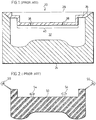
Figure 1 illustrates a sectional view of a prior art mold; -
Figure 2 illustrates a sectional view of a foam product made using the mold illustrated inFigure 1 ; -
Figures 3 and 4 illustrated an enlarged perspective view of a portion of a prior art vent device; -
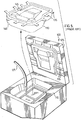
Figures 5 and6 illustrate production of a molded article in a prior art mold; -
Figure 7 illustrates a perspective view of a foam article made using the prior art mold illustrated inFigures 5 and6 ; -
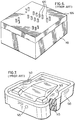
Figure 8 illustrates a sectional view of a preferred embodiment of the present mold shown during production of a molded article; -
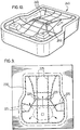
Figure 9 illustrates a top view of the mold illustrated inFigure 8 , partially ghosted to show the contents of the mold; -
Figure 10 illustrates a perspective view of the foam article made using the mold illustrated inFigures 8 and9 ; -
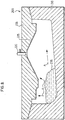
Figure 11 illustrates an enlarged sectional view of a modification of the mold illustrated inFigure 8 ; -
Figure 12 illustrates an enlarged portion of a foam product made using the mold illustrated inFigure 11 ; -
Figures 13-16 illustrate various foam articles made according to variations in the network of grooves made to the present mold; -
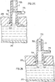
Figure 17 illustrates an enlarged sectional view of the present mold; -
Figure 18 illustrates an enlarged view a foam product made using the mold illustrated inFigure 17 ; -
Figure 19 is an enlarged perspective view of installation of a vent in the present mold; -
Figure 20 illustrates an enlarged sectional view of a vent in the present mold; -
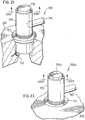
Figure 21 illustrates an enlarged perspective view of a first preferred vent installed in the present mold; -
Figure 22 is a sectional view along line XXII-XXII inFigure 21 ; -
Figure 23 illustrates an enlarged perspective view of a second preferred vent inFigure 20 installed in the present mold; -
Figure 24 illustrates a sectional view along line XXIV-XXIV inFigure 23 ; -
Figures 25-28 illustrate operation of the vent shown inFigures 21-22 ; and -
Figure 29 illustrates an enlarged perspective view of a foam product made using the vents illustrated inFigures 20-28 . - The liquid foamable polymeric composition according to the invention is based upon polyurethane, which will be referred throughout this specification.
- A first generation prior art mold will first be discussed, with reference to
Figures 1 and 2 , and a second generation prior art mold will then be discussed, with reference toFigures 3 and 4 . - With reference to
Figures 1 and 2 , a typical clam-shell mold, similar to those used for forming an automotive seat cushion from polyurethane foam, is indicated generally at 20 inFigure 1 .Mold 20 includes a lower mold 24 (also known in the art as a "bowl") and an upper mold 28 (also known in the art as a "lid") which are joined by a conventional hinge or other means (not shown).Lower mold 24 andupper mold 28, when closed, define acavity 32 which corresponds to the shape of the automotive seat cushion. - In use,
upper mold 28 is released fromlower mold 24 and a pre-determined amount of liquid foamable polyurethane composition is dispensed intolower mold 24.Upper mold 28 andlower mold 24 are closed and engaged to seal the mold, and the liquid foamable polyurethane composition expands, displacing the air withincavity 32. This displaced air exitscavity 32 through a relatively largeparting line vent 36 and through one or moretop vent passages 38 inupper mold 28. Further, as the polyurethane composition expands, polymerization of the composition occurs along with the evolution of gaseous CO2 incavity 32. This gaseous CO2 may also exitcavity 32 throughparting line 36 and throughtop vent passages 38. As is well known to those of skill in the art (and beyond the scope of this discussion), the liquid foamable polymeric composition eventually completely polymerizes and cures, acquiring the shape ofcavity 32. - As is also known to those of skill in the art, the amount of liquid foamable polyurethane composition dispensed in
cavity 32 must be selected to ensure thatcavity 32 will be substantially completely filled, in order to avoid the occurrence of underfill-associate foam collapse, voids and other foaming defects in the molded article. While the determination of the proper amount of liquid foamable polyurethane composition for a particular mold may generally be calculated, when using a first generation mold such asmold 20, it has been required to dispense an excess amount of polymeric composition into the mold to compensate for material which moves through and exits partingline vent 36 andtop vent passages 38. This excess, while assisting in ensuring thatcavity 32 is filled to avoid the occurrence of underfill-associate foam collapse, voids and other foaming defects in the molded articles, is in fact simply a wastage of valuable raw material which must be laboriously removed in a further post-production step. - In these first generation prior art molds, during the molding operation, air and the reaction gases produced from the expanding composition exit from
cavity 32 throughparting line vent 36 andtop vent passages 38 until the foam reaches the level of their respective entrances. - At this point, any further expansion of the foam results in movement of the foam into
parting line vent 36 and/ortop vent passages 38. In the simplest case of a cavity without irregularities, the foam reaches the level of the parting line vent and/or the vent passages at approximately the same time, which usually occurs at or near the maximum expansion point of the foam. Thus, provided that the proper amount of liquid foamable polyurethane composition has been dispensed into the cavity, only a small amount of foam enters the parting line vent and/or the vent passages ascavity 32 is completely filled. - In practice, however, as shown in
Figure 1 , most molds include irregularities in their cavities for various features required on the molded article. In such a case, the thickness and shape ofcavity 32 typically varies across the cavity and the entrance to partingline vent 36 andtop vent passages 38 in the mold may thus be located at different heights depending upon where they communicate withcavity 32. Further, localized areas of varying pressure also occur withincavity 32 due to the manner in which the foam and the gases produced collect in and move between the irregularities therein and thus the level of expanding foam mass in different parts ofcavity 32 at different times may vary. - Due to the above-mentioned factors, the foam in the cavity typically reaches the level of the parting line vents and/or different vent passages at different times while the foam is still expanding. For example, in a region wherein the top of
cavity 32 is lower than surrounding regions, such as indicated at 40 inFigure 1 , the foam may quickly reach thetop vent passages 38. As the foam is still rising in the rest ofcavity 32 and has not yet cured, a relatively significant amount of foam may entertop vent passages 38 in this region. - Again, as the amount of foam which enters parting line vents 36 and
top vent passages 38 reduces the amount of foam remaining incavity 32 by a like amount, it is necessary that the amount of liquid foamable polyurethane composition placed incavity 32 include an amount in excess of that required to fillcavity 32 to offset the foam which entered the parting line and vents. This excess amount, while necessary for proper operation of the prior art mold, is essentially wasted material which must be laboriously removed in a further post-production step and thus adds to the cost of forming the article. - Further, as shown in
Figure 2 , the foam which enterstop vent passages 38 forms "mushrooms" 54 (shown in ghosted line) of wasted material on the moldedarticle 50. Further, the material which enters parting line vents 36 forms "pancakes" 55 of wasted material on the moldedarticle 50. Typically,mushrooms 54 andpancakes 55 must be disconnected fromarticle 50 and removed from themold 20 prior to application of a finish cover to ensure a finished covered article which is of acceptable appearance and texture, and to preparemold 20 for re-use. The necessity of removingmushrooms 54 andpancakes 55 results in an increased labour cost associated with manufacturing the molded product. - In addition to the excess liquid foamable polyurethane composition which is added to offset the material extruded into the vents, excess liquid foamable polyurethane composition is also added to compensate for process variations due to changes in temperature, humidity, ambient pressure and minor changes in the composition of the liquid foamable polyurethane composition. Accordingly, in these first generation prior art molds, the wastage of material exiting the vents is inevitable.
- In United States patents
5,356,580 (Re.36,413 ),5,482,721 (Re.36,572 ) and5,587,183 [collectively referred to as "the Clark et al. patents"], there is disclosed a second generation mold. The second generation mold taught by the Clark et al. patents replaces parting line vents 36 inFigure 1 described hereinabove with improved parting line vents. These improved parting line vents are highly efficient vents that achieve the bulk of venting of the mold cavity. The second generation mold taught by the Clark et al. patents replacestop vent passages 38 ofFigure 1 described hereinabove with an improved top vent system. As is known in the art, top vent systems are needed to vent isolated regions (i.e., from the parting line vents) of the mold cavity. With references toFigures 3 and 4 hereof, a discussion of the operation this improved top vent system second generation mold will follow. - With reference to
Figures 3 and 4 , atop vent system 60 is illustrated.Top vent system 60 comprises acylindrical bore 62 and arelief pin 64 disposed withincylindrical bore 62. The exterior ofcylindrical bore 62 comprises a threadedportion 66 which engages a complementary threaded portion of the mold (not shown). In the illustrated embodiment, the portion ofrelief pin 64 nearest the opening ofcylindrical bore 62 is hexagonal in cross-section. The six points of the hexagonal cross-section ofrelief pin 64 are in engagement withcylindrical bore 62 and define six segment-shapedvent passages 68. The proximal end (not shown) ofrelief pin 64 comprises a cross-section complementary tocylindrical bore 62. An opening (not shown) is provided between the distal end and the proximal end (not shown) ofrelief pin 64 to allow gases enteringvent passages 68 to exittop vent system 60. -
Top vent system 60 is incorporated in a mold such as mold 20 (Figure 1 ) where it would replace each ofvent passages 38. In use, liquid foamable polyurethane composition is dispensed intocavity 32, andlower mold 24 andupper mold 28 are sealingly engaged. The air incavity 32 and the gases produced by the chemical reaction occurring in the expanding composition are vented throughvent passages 68. The viscosity of these gases are such that they flow relatively easily throughvent passages 68. Once the level of foam inmold 20 reaches the entrance to ventpassages 68, the foam enters ventpassages 68. Due to the presentation of a restriction byvent passages 68 to the expanding composition, the latter can only move slowly throughvent passages 68. Provided that the thickness ofvent passages 68 has been properly selected, the liquid foamable polymeric composition will stop moving therein before it travels a significant distance along the vents and before it the exit opening (not shown) oftop vent system 60. - Once expansion of the foaming mass is complete, the foam article produced is demolded from
mold 20. This is achieved by openinglower mold 24 andupper mold 28 and removing the foam article fromlower mold 24. During mold opening, any foam material which has expanded invent passages 68 will be torn from the foam article. Such torn material results in blockage ofvent passages 68 and thus, must be removed prior to reuse ofmold 20. This is achieved by slidingrelief pin 64 toward and extending it out of the distal end of cylindrical bore 62 (Figure 4 ). As described in the Clark et al. patents, this sliding operation results in the proximal end (not shown) of relief pin 64 (i.e., having a cross-section complementary to cylindrical bore 62) sweeping out ofcylindrical bore 62 any foam material blockingvent passages 68. - With reference to
Figures 5-6 , there is illustrated operation of amold 100 similar to that taught by the Clark et. al patents. Thus,mold 100 comprises alid 105 andbowl 110 which is realisably engageable withlid 105.Lid 105 includes a series of parting line or so-called "ribbon vents" disposed therein. - Also disposed in
lid 105 are a series of so-called auto vents 120 similar to those taught by the Clark et. al patents. - In use, a foamable composition (not shown) is disposed in
bowl 110 via adispenser 125.Lid 105 is then closed and the flowing mass is allowed to fill the mold cavity. Thereafter,lid 105 is swung open and afoam part 130 is removed frommold 100.Foam part 130 comprises a series offoam ribbons 135 which need not be trimmed and can simply be folded back during application of a trim cover to formpart 130. - Despite the advances made in the art by the teachings in the Clark et. al patents, there are situations where the quality of the product is less then desirable.
- Specifically, as discussed above, there are two defects which are seen from time to time: voids and underfill. Underfill is a surface phenomenon which manifests itself in
foam product 130 in the form ofsurface cavities 140. Further, the formation ofvoids 145 within foam element 130 ("subsurface voids") and on the surface of foam element 130 (not shown - "surface voids") is another problem. Surface voids tend to be manifested in the foam product as a localized area of the foam part that has not been formed - e.g., the foam composition does not expand to completely occupy a highly contoured section of the mold lid such that the resulting foam part is missing a section corresponding to the void. In conventional molding techniques,lid 105 is used to mold the so-called B-surface of the foam part whereas the surface ofbowl 110 is used is use to mold the so-called A-surface offoam part 130. Whilesurface cavities 140 can occur on any surface offoam element 130, they can be regularly present under the B-surface offoam element 130. It has been conventional in the art to respond to observation ofunderfill surface cavities 140 by placement of anotherautovent 120 in the area oflid 105 corresponding to the location ofvoid 140. - In the result, for a single mold, it has become commonplace to use on the order of 40 (or more) vents made up of ribbon vents 115 and
autovents 120 in asingle mold 100. Even with provision of such a larger number of vents, appearance ofunderfill surface cavities 140 and voids 145 (surface voids or subsurface voids) still occurs. - The present inventors have adapted a completely different approach to improving venting of gas formed as the foaming mass fills the mold cavity.
- Specifically, the present inventors have discovered that it is not necessary to have such a large number of vents nor is it necessary to rely on such vents for venting a localized portion of the mold cavity. Thus, the present inventors have discovered that one or more grooves (or slots) in the surface of the mold cavity can be used as a conduit to funnel, draw, siphon, etc. gas to be vented to a conventional vent without the need to place a vent in each area where gas is expected to be vented.
- In a highly preferred embodiment of the invention, these grooves or slots are disposed in a intersecting or a grid-like fashion combined with provision of at least one such groove/slot in the periphery of the mold cavity. These groove/slot function as siphons (e.g. via a capillary effect) to facilitate removal of gas from the mold cavity.
- Thus, in a preferred embodiment, the venting approach in the present mold relates to use of previous local vents as effective area vents by disposing a plurality of grooves/slots in the mold cavity surface. The capacity of these grooves/slots to transport gas effectively is a function of the interaction with the natural growth of the rising foam, the thickness of the area in which the grooves/slots are contained and the obstruction effect of the geometries in the path to the vents. Thus, the grooves-slots are effective for channeling gas to be vented to a vent.
- As will be developed further below, it is possible to connect this network or grid-like arrangement of grooves/slots to conventional vents such that those taught in the Clark et. al patent. The improvement is a significant reduction in the number of vents required to achieve proper venting and the ability to produce parts which are substantially free of voids and underfill - the provision of such parts is a particularly significant advantage of the present invention.
- With reference to
Figure 8 , there is illustrated amold 200 comprising alid 205 and abowl 210 which are releasably engageable in a manner similar to that described above with respect tomold 100. Fourvents 220 are disposed inlid 205. Also disposed inlid 205 is anetwork 225 of grooves.Network 225 extends to aperipheral portion 230 of the mold cavity. - As can be seen with reference to
Figure 9 ,network 225 is connected tovents 220. - With further reference to
Figure 8 , once a liquidfoamable composition 235 is dispensed intomold 200,composition 235 expands in the direction of arrows A. During this process, gas is produced and the pressure in mold cavity increases. The grooves/slots innetwork 225 are effectively disposed ahead of foam flow and are reliable to channel or funnel gas towardvents 220 even thoughvents 220 are not disposed throughout the entire surface oflid 205. The drawing out of gasses produced during expansion is facilitated by placement ofvents 220 at or near the peak of the contours inlid 205. - The resulting
foam part 240 is shown inFigure 10 . By adopting the combination ofnetwork 225 and vents 220,foam part 240 can be produced with virtually no underfill or voiding. Further, as shown inFigure 10 foam part 240 comprises a "negative" ofnetwork 225 on the B-surface thereof in the form of anetwork 245 of foam ridge. In essence,foam part 240 is completely trim-free and can be sent to trim cover operations without the need to remove flash or other excess materials. - With reference to
Figure 11 , there is illustrated adaptation ofnetwork 225 of grooves/slots to a parting line or so-called "ribbon vent". In this case, vent 220 has been replaced with aribbon vent 222 similar to the one described in Clark et al. patents discussed above. Further,network 225 of grooves/slots has been extended to rise to apeak 212 of the mold cavity. - The resulting
part 242 is shown inFigure 12 where a "negative" 227 ofnetwork 225 has been produced - i.e., the "negative" is simply anetwork 227 of molded foam ridges which fillednetwork 225 during expansion offoamable composition 235. As shown inFigure 12 ,foam element 242 comprises a series ofribbons 235 produced in ribbons vents 220. - With reference to
Figures 13 and 14 , there is illustrated sectional and enlarged sectional perspective views of afoam part 300 made in accordance with the present mold, not according to the invention. - For ease of illustration and understanding, the resulting foam part is illustrated. However, those of skill in the art will understand based on this specification that these foam parts were made using the network or grid-like orientation of groove/slots. Thus,
foam part 300 comprises a lip (or raised edge) 305. As shown,network 325 of foam ridges includes aperipheral foam ridge 330 connected withnetwork 325. In this case, a series of connectingfoam ridges 332 interconnectperipheral ridge 330 to anumber ribbons 335.Network 325,peripheral foam ridge 330 and connectingfoam ridges 332 are produced by a complementary network of grooves/slots. - With reference to
Figure 15 , there is illustrated afoam element 400 comprising alip portion 405 and anetwork 425 of ridges produced from complementary grooves/slots in a mold not in accordance with the present invention.Foam part 400 further comprises aperipheral ridge 430 formed from a complementary groove/slot in a mold according to the present invention.Foam part 400 further comprises connectingridges 432 formed from complementary grooves/slots which connect to ribbon vents (not shown) in the manner discussed above. These ribbon vents result in production ofribbons 435 as discussed above. - The B-surface of
foam part 400 comprises a raisedsection 440. Raisedsection 440 has a localizednetwork 445 of ridges formed from a complementary network of grooves/slots in the mold according to the invention. Sincenetwork 445 is isolated fromnetwork 425, a vent (shown in ghosted outline above section 440) is used to facilitate venting of the mold cavity corresponding to the region defined bysection 440. Provision ofisolated network 445 and a separate vent allow for the production of raisedsection 440 without the occurrence of underfill or voids - i.e., this notwithstanding the fact that raisedsection 440 is highly contoured and is almost right-angled with respect to the major portion of the B-surface offoam part 400. -
Foam part 400 further comprises a raisedsection 450 which is shorter than raisedsection 440. To achieve proper venting of the section of the mold cavity corresponding to raisedsection 450 without the occurrence of voids or underfill, a portion of the network of grooves/slots in the mold is disposed on the portion of the mold cavity corresponding to raisedportion 450 so that this portion of the mold cavity is vented via the network of grooves/slots resulting in the production ofnetwork 425. -
Figure 16 illustrates afoam part 500 having a higher raisedsection 540 and a lower raisedsection 550 similar to those shown inFigure 15 with respect tofoam part 400. In the case offoam part 500,peripheral ridge 530 and the ridges of "main" network 525 and the ridges ofnetwork 545 are all interconnected thereby obviating the need for connecting ridges and ribbons, including obviating the need for ribbon vents in the mold used to producefoam part 500. Rather, autovent vents or the like can be used at the location shown in ghosted outline shown inFigure 16 to achieve effective area venting of the mold cavity. -
Figure 18 (not according to the invention) shows an enlarged portion of a slightly modified version ofelement 400 wherein "mini"network 447 of ridges has been slightly modified compared to "mini"network 445 inFigure 15 . -
Figure 17 illustrates an enlarged section view of a portion of the mold used to producedelement 400 shown inFigure 18 . Thus, a "main" network of grooves/slots is provided and is connected to a peripheral groove/slot, connected grooves/slots and ribbon vent as discussed above. Peak 212 oflid 205 is provided with a "mini"network 247 of grooves/slots which are interconnected and isolated with respect to "main"network 225. "Mini"network 247 of grooves-slots is connected to avent 220 as discussed above. - Thus, in operation, gases in the main portion of the mold cavity will be vented via "main"
network 225 of grooves/slots, peripheral groove/slot, connection grooves/slots and ribbon vents (all not shown inFigure 17 but referred to above) whereas gas that may b trapped inpeak 212 will be vented via "mini"network 247 of grooves/slots and vent 220. - With reference to
Figure 20 , there is shown a schematic representation of connection ofvent 220 tolid 205 ofmold 200. Thus, vent 220 comprises a threadedportion 221.Lid 205 comprises an internally threadedportion 206 which compleents threadedportion 221 ofvent 220. Thus, vent 220 is simply threaded intolid 205 via threadedportions - Vent 220 can take a number of different forms. Thus, with reference to
Figure 20 , there is shown a large sectional view of avent 600 disposed inlid 205. Vent 600 maybe constructed in a manner similar to vent assembly 98 described in the Clark et. al patents. - With reference to
Figures 21, 22 and 25-28 , there is illustrated analternate vent 700 which may be used in place of and/or in addition to one or both ofvents - Thus, vent 700 comprises a threaded
section 721 which maybe engaged with a complementary threaded section (not shown) inlid 205 as discussed above with reference toFigure 19 . -
Vent 700 comprises apassageway 705 in which is disposed anobstruction 710. Branching off ofpassageway 705 is aconduit 715. Disposed belowvent 700 is a pair of opposed sensor elements 720 (only one is shown inFigure 21 ).Sensor element 720 maybe an optical sensor (e.g., infrared and the like), an acoustical sensor, a capacitance sensor and the like. - The operation of
vent 700 will now be discussed with reference toFigures 25-28 . - Thus, a liquid
foamable composition 235 is dispensed inbowl 210 ofmold 200 as discussed above with reference toFigure 8 .Lid 205 is then closed with respect tobowl 210. Asfoamable composition 235 expands, gases are produced andexit vent 700 viaconduit 715 following the path of arrows B. Asfoamable composition 235 fills the mold cavity, it reachessensors 720 invent 700. When this happens,obstruction 710 is actuated to move in the direction of arrow C thereby effectively closing off escape of gas via conduit 715 - i.e., vent 700 is, for all intents and purposes, closed (Figure 27 ). - Thereafter,
obstruction 710 is moved in the direction of arrow D and the resulting foam part is demolded as discussed above. Alternatively, the resulting foam part can be demolded and thenobstruction 710 can be moved in the direction of arrow D in readiness for production of next foam part. - Thus, those of skill in the art will understand that
vent 700 operates as a relatively high capacity vent which has a sensor-actuated shot off system effectively sealing off escape of gas through the vent. In other words, vents 700 is operable between a first position in which it operates as a high capacity vent and a second position in which the vent is effectively sealed. - An alternative to this approach is illustrated with respect to a modification of
vent 700 to vent 700a shown inFigures 23-24 . InFigures 23-24 , the only significant change invent 700a is replacement ofobstruction 710 withobstruction 710a. -
Obstruction 710a is similar to the obstruction appearing invent 600 described above and vent assembly 98 described in the Clark et. al patents.Obstruction 710a is actuated in the same manner as described with reference toobstruction 710 inFigures 25-28 . - The resulting difference is that, unlike
vent 700 illustrated inFigures 25-28 , vent 700a illustrated inFigures 23-24 is operable between a first position in which the vent acts as a relatively high capacity, active vent and a second position in which the vent acts as low capacity, passive vent (i.e., in the second position the vent is not effectively sealed off as it is in the embodiment described with reference toFigures 25-28 ). The advantage of this approach is that the number of vents needed is reduced (as was the case with vent 700) since the vent inFigures 23-24 operates as a high capacity vent in the first position while, on the other hand, the need to use precise timing to close off the vent as shown inFigures 25-28 is alleviated withvent 700a shown inFigures 23-24 since gas will continue to escape the vent even afterobstruction 705 is actuated to be in the second (low capacity, passive vent) position. - In some cases, this can obviate the need for
sensors 720 where the same part is being produced in the same mold. Specifically, a timing system can be used to moveobstruction 710a from its first (high capacity, active vent) position to its second (low capacity, passive vent) position. - With reference to
Figure 29 , there is illustrated an enlarged view of a portion of foam part 240 (see alsoFigure 10 ) comprising a portion ofnetwork 245 of foam ridge element formed bynetwork 225 of grooves/slots inmold 200. Further, anextruded section 250 is shown where foam cured nearvent - While this invention has been described with reference to illustrative embodiments and examples, the description is not intended to be construed in a limiting sense. Thus, various modifications of the illustrative embodiments, as well as other embodiments of the invention, will be apparent to persons skilled in the art upon reference to this description. For example, it is possible to modify
lid 205 ofmold 200 to modify the shape and/or dimension of extrudedportion 250 in resultingfoam part 240. Alternatively, it is possible to modifylid 205 ofmold 200 to eliminate production of extrudedportion 250 in resultingfoam part 240. Still further, it is possible to modify interconnection ofvents lid 205 such that the distal portion ofvents lid 205. Still further, it is possible to modify the network of grooves/slots 225 to have a different design. For example, it is possible to design a network of grooves/slots to include a diamond-shaped repeating pattern, optionally including a series of substantially parallel grooves/slots wherein each groove/slot bisects a row of diamonds in the repeating pattern. Alternatively, it is possible to design a network of grooves/slots to include a series of substantially parallel grooves/slots (i.e., in a so-called radiator type arrangement with a spacing between adjacent pairs of grooves/slots in the range of from about 2 cm to about 5 cm). In each case, it is preferred to included a perimeter groove/slot connected to the network of grooves/slots, more preferably connected to each groove/slot in the network.
Claims (5)
- A device (200) for producing molded automotive seat cushions from polyurethane foam, in combination with a liquid foamable polyurethane composition, the device (200) comprising a lid (205) and a bowl (210) releasingly engageable between an open position and a closed position, the closed position defining a mold cavity, at least one of the lid (205) and the bowl (210) comprising: (i) a plurality of vents (220), each vent (220) having a passageway for gas to escape from the mold cavity and an obstruction in the passageway, the obstruction and the passageway combining to form at least one opening, and (ii) a plurality of interconnected grooves (225) on a surface of the mold cavity, the plurality of interconnected grooves (225) being arranged to be in fluid communication with the plurality of vents (220).
- The device (200) of claim 1, wherein the obstruction and the passageway combine to form a plurality of openings.
- The device (200) of claim 1 or 2, wherein the at least one opening has a segment-shaped cross-section.
- A process for producing a molded automotive seat cushions from polyurethane foam in the device defined in one of claims 1 to 3, the process comprising the steps of: (i) dispensing a liquid foamable polyurethane composition in the bowl; (ii) translating gas in the mold cavity to the plurality of interconnected grooves, (iii) translating gas from the plurality of interconnected grooves to the plurality of vents; (iv) substantially filling the mold cavity with the liquid foamable polyurethane moldable composition, and (v) allowing gas to escape from the plurality of vents to an exterior of the device.
- The process defined in Claim 4, wherein the mold is in the open position during Step (i) and in the closed position during Step (iv).
Priority Applications (2)
| Application Number | Priority Date | Filing Date | Title |
|---|---|---|---|
| PL12166482T PL2487018T3 (en) | 2004-05-12 | 2005-05-10 | Vented mold and method for producing molded article |
| SI200532142T SI2487018T1 (en) | 2004-05-12 | 2005-05-10 | Vented mold and method for producing molded article |
Applications Claiming Priority (3)
| Application Number | Priority Date | Filing Date | Title |
|---|---|---|---|
| US57007504P | 2004-05-12 | 2004-05-12 | |
| US10/973,985 US7481637B2 (en) | 2004-05-12 | 2004-10-27 | Vented mold and method for producing molded article |
| EP05742410.3A EP1750917B1 (en) | 2004-05-12 | 2005-05-10 | Vented mold and method for producing molded article |
Related Parent Applications (3)
| Application Number | Title | Priority Date | Filing Date |
|---|---|---|---|
| EP05742410.3 Division | 2005-05-10 | ||
| EP05742410.3A Division-Into EP1750917B1 (en) | 2004-05-12 | 2005-05-10 | Vented mold and method for producing molded article |
| EP05742410.3A Division EP1750917B1 (en) | 2004-05-12 | 2005-05-10 | Vented mold and method for producing molded article |
Publications (2)
| Publication Number | Publication Date |
|---|---|
| EP2487018A1 EP2487018A1 (en) | 2012-08-15 |
| EP2487018B1 true EP2487018B1 (en) | 2017-01-18 |
Family
ID=35308658
Family Applications (3)
| Application Number | Title | Priority Date | Filing Date |
|---|---|---|---|
| EP05742410.3A Active EP1750917B1 (en) | 2004-05-12 | 2005-05-10 | Vented mold and method for producing molded article |
| EP12166482.5A Active EP2487018B1 (en) | 2004-05-12 | 2005-05-10 | Vented mold and method for producing molded article |
| EP12166485.8A Active EP2487019B1 (en) | 2004-05-12 | 2005-05-10 | Vented mold |
Family Applications Before (1)
| Application Number | Title | Priority Date | Filing Date |
|---|---|---|---|
| EP05742410.3A Active EP1750917B1 (en) | 2004-05-12 | 2005-05-10 | Vented mold and method for producing molded article |
Family Applications After (1)
| Application Number | Title | Priority Date | Filing Date |
|---|---|---|---|
| EP12166485.8A Active EP2487019B1 (en) | 2004-05-12 | 2005-05-10 | Vented mold |
Country Status (16)
| Country | Link |
|---|---|
| US (5) | US7481637B2 (en) |
| EP (3) | EP1750917B1 (en) |
| JP (4) | JP4765064B2 (en) |
| KR (3) | KR20130138857A (en) |
| CN (2) | CN102490291B (en) |
| AU (1) | AU2005240236B2 (en) |
| BR (1) | BRPI0511002B1 (en) |
| CA (2) | CA2566760C (en) |
| DE (2) | DE112005000008T5 (en) |
| ES (2) | ES2669584T3 (en) |
| HU (2) | HUE038777T2 (en) |
| MX (1) | MXPA06013082A (en) |
| PL (2) | PL1750917T3 (en) |
| RU (1) | RU2399489C2 (en) |
| SI (2) | SI2487018T1 (en) |
| WO (1) | WO2005108039A1 (en) |
Families Citing this family (42)
| Publication number | Priority date | Publication date | Assignee | Title |
|---|---|---|---|---|
| US7481637B2 (en) * | 2004-05-12 | 2009-01-27 | Woodbridge Foam Corporation | Vented mold and method for producing molded article |
| JP4884727B2 (en) * | 2005-08-30 | 2012-02-29 | 株式会社イノアックコーポレーション | Molding equipment |
| DE102006004818A1 (en) * | 2006-01-26 | 2007-08-02 | Sumitomo Electric Bordnetze Gmbh | Mold for producing rigid foam components, e.g. polyurethane foam sockets, has freely shaped regions of the mold cavity lowered to facilitate deaeration of mold and give smooth product surface |
| JP4839911B2 (en) * | 2006-03-22 | 2011-12-21 | 株式会社ブリヂストン | Foam molded products and molds |
| US7641459B2 (en) * | 2006-05-01 | 2010-01-05 | Sealed Air Corporation (Us) | Foam cushion molding system and method |
| US20080121336A1 (en) * | 2006-11-24 | 2008-05-29 | Tachi-S Co., Ltd. | Method for forming a foamed product integral with trim cover assembly |
| US20080213534A1 (en) * | 2007-01-05 | 2008-09-04 | Mcevoy James T | Grained parting lines in mold for foam articles |
| US8206143B2 (en) * | 2007-12-13 | 2012-06-26 | Biomet Manufacturing Corp. | Modular articulating cement spacer |
| DE102008014261A1 (en) | 2008-03-13 | 2009-09-17 | Car Trim Foamtec Gmbh | Two-piece foam material composite body producing method for car seat, involves firmly connecting foam material body with another foam material body for producing foam material composite body |
| JP5380909B2 (en) * | 2008-05-30 | 2014-01-08 | 株式会社ブリヂストン | Mold and molding method of resin foam molding |
| FR2935631A1 (en) * | 2008-09-05 | 2010-03-12 | C3J | Mold for forming e.g. cellular container in agrofood field, has slits formed between cavity and chamber and intersected by two or more lines based on shape of relief and complexities of blocks |
| US8991930B2 (en) * | 2008-09-22 | 2015-03-31 | Johnson Controls Technology Company | Closed cell foam vehicle interior component and method of making same |
| JP4737295B2 (en) * | 2009-01-19 | 2011-07-27 | マツダ株式会社 | Molding method and molding apparatus for foamed resin molded product |
| CN101544777B (en) * | 2009-05-08 | 2011-08-24 | 南京红宝丽股份有限公司 | Rigid urethane foam moulded foaming device and method for foaming using same |
| CN101927547B (en) * | 2010-07-28 | 2012-11-14 | 深圳市银宝山新科技股份有限公司 | Ventilation structure for foaming mould |
| WO2012029823A1 (en) * | 2010-08-31 | 2012-03-08 | 積水化成品工業株式会社 | Foaming mold and foam molded article formed using same |
| DE202010012729U1 (en) * | 2010-09-22 | 2011-09-23 | Otto Wiesmayer | Tool and device for producing a foam molding and molding with ventilation device |
| IT1403233B1 (en) | 2010-11-24 | 2013-10-17 | Persico Spa | METHOD FOR MOLDING THERMOFORMABLE AND MOLD PANELS FOR ITS IMPLEMENTATION. |
| JP5867018B2 (en) * | 2011-11-25 | 2016-02-24 | トヨタ紡織株式会社 | Molding equipment |
| JP5014508B1 (en) * | 2011-11-30 | 2012-08-29 | 株式会社ブリヂストン | Method for producing foam molded article |
| CN104114410B (en) | 2011-12-13 | 2016-12-21 | 维尔克有限公司 | In-molded contact secured product |
| CN102814941A (en) * | 2012-09-03 | 2012-12-12 | 晟扬精密模具(昆山)有限公司 | Production mould for rear cover of notebook computer display |
| CN103029263B (en) * | 2012-12-07 | 2016-03-02 | 法国圣戈班玻璃公司 | Adapted to injection system and injection moulding process, automobile glass encapsulation, vehicle window |
| CN103042648B (en) * | 2012-12-21 | 2015-01-21 | 苏州天华超净科技股份有限公司 | Preparation method for polyurethane injection molded shoes and preparation mold |
| DE102013102044A1 (en) * | 2013-03-01 | 2014-09-04 | Bayerische Motoren Werke Aktiengesellschaft | Ventilation device for ventilating cavity of tool device for production of fiber composite workpieces, has sensor device annularly formed relative to vent hole to recognize free-flowing matrix material before penetration into vent hole |
| JP6300086B2 (en) * | 2014-04-17 | 2018-03-28 | スズキ株式会社 | Seat cushion |
| CN104924494A (en) * | 2015-06-08 | 2015-09-23 | 太仓力九和塑胶工业有限公司 | Mould for formation of shock-absorbing material and forming method of shock-absorbing material |
| US9918526B2 (en) | 2015-06-17 | 2018-03-20 | Velcro BVBA | Mold-in touch fastening product |
| US9826801B2 (en) | 2015-06-17 | 2017-11-28 | Velcro BVBA | Mold-in touch fastening product |
| JP6586310B2 (en) * | 2015-07-10 | 2019-10-02 | 東京電力ホールディングス株式会社 | Steel pipe |
| MX2018002150A (en) * | 2015-08-31 | 2018-06-06 | Proprietect Lp | Vented mold. |
| CN106113332B (en) * | 2016-08-31 | 2019-05-28 | 山东豪迈机械科技股份有限公司 | A kind of automatic control exhaust apparatus and tire-mold |
| CN106113333B (en) * | 2016-08-31 | 2019-02-22 | 山东豪迈机械科技股份有限公司 | A kind of automatic control exhaust apparatus and tire-mold |
| CN106426724A (en) * | 2016-10-26 | 2017-02-22 | 丹阳市金业来车辆装饰件有限公司 | Steel foam forming mold of automobile interior and exterior parts and mold preparation method |
| CN107214904A (en) * | 2017-06-27 | 2017-09-29 | 湖南亚太实业有限公司 | A kind of closed pore PU foaming mould structures |
| US11007687B2 (en) | 2017-10-02 | 2021-05-18 | Legacy Foam Llc | Polyurethane injection system and method |
| ES1211970Y (en) * | 2018-04-20 | 2018-07-31 | Matrival S L | MOLD FOR MANUFACTURE OF VEHICLE SEAT PARTS |
| CN108819078B (en) * | 2018-06-11 | 2024-06-28 | 陈卫建 | Vehicle-mounted movable foam plastic processing rubber head machine |
| CN109813032A (en) * | 2018-12-27 | 2019-05-28 | 合肥华凌股份有限公司 | Foaming cover board, refrigerator doors end cap and refrigerator |
| JP6647604B1 (en) * | 2019-02-25 | 2020-02-14 | ニッタモールド株式会社 | Rock fasteners |
| US11555622B2 (en) | 2019-12-19 | 2023-01-17 | International Business Machines Corporation | Intelligent context-based control of air flow |
| WO2021126897A1 (en) * | 2019-12-20 | 2021-06-24 | Arris Composites Inc. | Method for hybrid preforms |
Citations (1)
| Publication number | Priority date | Publication date | Assignee | Title |
|---|---|---|---|---|
| WO1999022924A1 (en) * | 1997-10-31 | 1999-05-14 | Woodbridge Foam Corporation | Vent device, vented mold and method for producing a molded article |
Family Cites Families (79)
| Publication number | Priority date | Publication date | Assignee | Title |
|---|---|---|---|---|
| US667861A (en) * | 1900-08-25 | 1901-02-12 | Basle Chemical Works | Process of producing chlorids of aromatic sulfonic acids. |
| GB550014A (en) | 1941-05-12 | 1942-12-18 | British Tyre & Rubber Company | Improvements in or relating to tools for blanking, forming and flanging metal and other materials |
| GB667861A (en) | 1949-08-04 | 1952-03-12 | Wingfoot Corp | Venting of foamed latex molds |
| GB732287A (en) | 1952-04-12 | 1955-06-22 | Giuseppe Olmo Spa | Improved manufacture of articles made of spongy or cellular rubber |
| FR1074407A (en) * | 1952-04-12 | 1954-10-05 | P Az Giuseppe Olmo Soc | Mold for spongy or cellular rubber articles made from rubber latex or natural gum |
| LU34640A1 (en) | 1956-04-05 | |||
| US3632249A (en) * | 1969-07-01 | 1972-01-04 | Cypro Inc | Apparatus for molding hollow plastic articles |
| US3553790A (en) * | 1969-11-10 | 1971-01-12 | Goodyear Tire & Rubber | Concealed tire vent mold |
| US3650648A (en) * | 1970-02-25 | 1972-03-21 | Union Carbide Corp | System for molding electronic components |
| US3739438A (en) * | 1970-02-25 | 1973-06-19 | Union Carbide Corp | System for molding electronic components |
| US3692090A (en) * | 1970-07-20 | 1972-09-19 | Goodyear Tire & Rubber | Method of making a vented tire mold |
| DE2212609A1 (en) | 1972-03-16 | 1973-10-04 | Ver Foerderung Inst Kunststoff | Mould deaeration - during foaming using hollow cylinder with air removal slit introduced into opening in mould wall |
| US4090541A (en) * | 1976-11-23 | 1978-05-23 | Baxter Travenol Laboratories, Inc. | Flexible collapsible container |
| JPS5941855B2 (en) * | 1976-11-26 | 1984-10-11 | 株式会社ブリヂストン | Manufacturing method of synthetic resin board |
| JPS54133570A (en) | 1978-04-10 | 1979-10-17 | Kohkoku Chem Ind | Production of cushion and metal mold for forming same |
| FR2428519A1 (en) * | 1978-06-13 | 1980-01-11 | Ameublement Ind Et Tech | PLUG FOR CAST HOLE OF EXPANDED MATERIAL IN A MOLD |
| US4431047A (en) * | 1979-09-27 | 1984-02-14 | Ube Industries, Ltd. | Gas-venting arrangement incorporated with a mold |
| JPS56149351A (en) * | 1980-04-22 | 1981-11-19 | Nippon Telegr & Teleph Corp <Ntt> | Coating method for optical fiber |
| JPS5853606A (en) * | 1981-09-25 | 1983-03-30 | Toshiba Corp | Installing method of condenser and steam turbine |
| JPS5853606U (en) * | 1981-10-09 | 1983-04-12 | 旭化成株式会社 | mold |
| JPS5869422U (en) | 1981-11-04 | 1983-05-11 | 池田物産株式会社 | foam mold |
| CA1202736A (en) * | 1983-01-31 | 1986-04-01 | Jeffrey D. Swenson | Membrane covered cushion having indented pattern and method for making same |
| US4548861A (en) * | 1983-09-29 | 1985-10-22 | The Boeing Company | Foam rigidizing process and products produced therewith |
| JPS60127112A (en) * | 1983-12-14 | 1985-07-06 | Matsushita Electric Works Ltd | Air venting device of molding die |
| GB2161375A (en) * | 1984-07-09 | 1986-01-15 | Milsco Mfg Co | Composite foam-seat cushion and method of preparation |
| JPS61292926A (en) * | 1985-06-21 | 1986-12-23 | Hitachi Hokkai Semiconductor Ltd | Molding method and molding equipment |
| JPH0333453Y2 (en) | 1985-11-06 | 1991-07-16 | ||
| US4718153A (en) * | 1986-04-10 | 1988-01-12 | Steelcase Inc. | Cushion manufacturing process |
| DE3787507T2 (en) * | 1986-11-04 | 1994-01-20 | Ube Industries | Device for degassing a metal mold. |
| US4987947A (en) * | 1987-06-05 | 1991-01-29 | Toshiba Kikai Kabushiki Kaisha | Gas venting device for molding operations |
| JPH065133Y2 (en) * | 1987-09-07 | 1994-02-09 | 西川化成株式会社 | Urethane foam type degassing device |
| US4874308A (en) * | 1988-04-04 | 1989-10-17 | Atlas Gary N | Vacuum assisted transfer mold and vent pin |
| BG49799A1 (en) | 1989-01-09 | 1992-02-14 | Inst Elektropromishlenost Niko | Stator package of electric machine |
| JP2743475B2 (en) * | 1989-05-30 | 1998-04-22 | トヨタ自動車株式会社 | Foam molding method |
| JPH0763980B2 (en) * | 1991-03-13 | 1995-07-12 | 河西工業株式会社 | Method and apparatus for molding laminated molded body |
| JPH0585609U (en) | 1992-04-24 | 1993-11-19 | 西川化成株式会社 | Foam mold |
| CA2077363C (en) | 1992-09-02 | 1996-09-03 | Leslie Edward Clark | Vented mold and use thereof |
| JP2582175Y2 (en) | 1992-10-08 | 1998-09-30 | 株式会社ヒロタニ | Press forming equipment for automotive interior materials |
| JPH06218743A (en) | 1993-01-22 | 1994-08-09 | Bridgestone Corp | Foaming mold |
| US5466404A (en) * | 1993-10-06 | 1995-11-14 | Atoma International Inc. | Controlled venting during molding of polyurethane foam |
| JPH07108346A (en) | 1993-10-08 | 1995-04-25 | Toyota Motor Corp | Metallic mold for forming foam pattern |
| JPH07156152A (en) | 1993-12-01 | 1995-06-20 | Kyokuto Seiki Kk | Venting metal fitting of foaming mold for urethane foam |
| US5650105A (en) * | 1994-05-24 | 1997-07-22 | Yocum; Fred D. | Method for making a loudspeaker cone with an integral surround |
| JP3137539B2 (en) | 1994-07-18 | 2001-02-26 | テイ・エス テック株式会社 | Mold for resin press molding with skin |
| JP3149705B2 (en) | 1994-10-18 | 2001-03-26 | トヨタ自動車株式会社 | Mold with vent |
| JPH08187737A (en) | 1995-01-11 | 1996-07-23 | Inoac Corp | Base material for pad molded form and manufacture thereof |
| JP3487566B2 (en) | 1995-03-02 | 2004-01-19 | タカニチ株式会社 | Mold for foam molding |
| JP2981423B2 (en) * | 1995-07-10 | 1999-11-22 | 住友ゴム工業株式会社 | Pneumatic tire, method of manufacturing the same, and tire mold used for the same |
| FR2736823B1 (en) * | 1995-07-18 | 1997-12-19 | Roux Georges | PROCESS FOR THE MANUFACTURE OF ANTI-PRESSURE MATTRESS |
| JPH09174577A (en) | 1995-12-26 | 1997-07-08 | Tokai Kogyo Kk | Molding of foamed molded object |
| JPH09239785A (en) | 1996-03-06 | 1997-09-16 | Daizo Kotaki | Mold apparatus for molding plastic |
| DE19701728C2 (en) * | 1997-01-20 | 1998-12-10 | Hennecke Gmbh | Process and device for producing foamed polyurethane molded articles |
| AU7633298A (en) * | 1997-05-30 | 1998-12-30 | Woodbridge Foam Corporation | Vented mold and method for producing a molded article |
| JPH115225A (en) | 1997-06-16 | 1999-01-12 | Mitsuboshi Belting Ltd | Manufacture of synthetic precious wood with groove |
| DE19734300A1 (en) | 1997-08-08 | 1999-02-11 | Friedrich Priehs | Process and mold for producing molded parts from biopolymers |
| JPH11245239A (en) | 1998-02-27 | 1999-09-14 | Nichiha Corp | Production of template |
| CN1139471C (en) * | 1998-03-31 | 2004-02-25 | 戴伸工业公司 | Synthetic resin internal foam molding machine and method |
| JPH11342514A (en) | 1998-03-31 | 1999-12-14 | Daisen Kogyo:Kk | Mold assembly for foam molding |
| JP2000006155A (en) | 1998-06-18 | 2000-01-11 | Ikeda Bussan Co Ltd | Structure of mold for vehicle interior trim base material |
| AU750088C (en) * | 1998-07-27 | 2003-06-12 | Dunlop Gmbh | Tyre vulcanisation mould with blocking mechanisms fitted in de-airing holes |
| JP3592133B2 (en) | 1999-05-07 | 2004-11-24 | 積水化成品工業株式会社 | Core vent used for foam resin molding equipment |
| JP2000334761A (en) | 1999-05-31 | 2000-12-05 | Daisen Kogyo:Kk | Foamed molding excellent in design effect |
| JP4206572B2 (en) | 1999-08-09 | 2009-01-14 | 株式会社イノアックコーポレーション | Foam mold |
| DE19938140A1 (en) * | 1999-08-16 | 2001-03-08 | Fehrer F S Gmbh & Co Kg | Molding foam polymer in closed mold cavity is accompanied by gas venting, with sensor detecting state of filling and causing special vent valve to confine foam |
| US6367765B1 (en) * | 1999-09-09 | 2002-04-09 | Klaus A. Wieder | Mold vent |
| US6255142B1 (en) * | 1999-10-29 | 2001-07-03 | Nordson Corporation | Method for underfilling semiconductor devices |
| JP2001225362A (en) | 2000-02-15 | 2001-08-21 | Tdk Corp | Molding mold and molding method |
| JP2002187143A (en) | 2000-12-19 | 2002-07-02 | Nishikawa Kasei Co Ltd | Molding tool for foam |
| JP2002307459A (en) | 2001-04-09 | 2002-10-23 | Nishikawa Kasei Co Ltd | Foaming mold |
| JP2003019718A (en) | 2001-07-06 | 2003-01-21 | Toyo Tire & Rubber Co Ltd | Method and apparatus for foaming |
| JP3951653B2 (en) * | 2001-09-13 | 2007-08-01 | 豊田合成株式会社 | Manufacturing method of molded products |
| JP2003103344A (en) | 2001-09-28 | 2003-04-08 | Asahi Tec Corp | Manufacturing method for molding mold and molding mold manufactured thereby |
| US6553809B1 (en) * | 2001-11-01 | 2003-04-29 | Plastic Technologies, Inc. | Method and apparatus for detecting holes in plastic containers |
| JP2004058494A (en) | 2002-07-30 | 2004-02-26 | Toray Ind Inc | Method for manufacturing rigid urethane foam and double-sided molding mold used in this method |
| DE10325097A1 (en) * | 2003-06-03 | 2004-12-23 | Arvinmeritor Gmbh | foaming |
| US7481637B2 (en) * | 2004-05-12 | 2009-01-27 | Woodbridge Foam Corporation | Vented mold and method for producing molded article |
| US7444700B2 (en) * | 2004-10-21 | 2008-11-04 | Sears Manufacturing Co. | Seat cushion with integral cover attachment |
| JP4884727B2 (en) * | 2005-08-30 | 2012-02-29 | 株式会社イノアックコーポレーション | Molding equipment |
| US7934774B2 (en) * | 2006-03-31 | 2011-05-03 | Lear Corporation | Vehicle seat assembly having a hardness gradient |
-
2004
- 2004-10-27 US US10/973,985 patent/US7481637B2/en active Active
-
2005
- 2005-05-10 HU HUE05742410A patent/HUE038777T2/en unknown
- 2005-05-10 CA CA2566760A patent/CA2566760C/en active Active
- 2005-05-10 PL PL05742410T patent/PL1750917T3/en unknown
- 2005-05-10 PL PL12166482T patent/PL2487018T3/en unknown
- 2005-05-10 HU HUE12166482A patent/HUE033646T2/en unknown
- 2005-05-10 EP EP05742410.3A patent/EP1750917B1/en active Active
- 2005-05-10 MX MXPA06013082A patent/MXPA06013082A/en active IP Right Grant
- 2005-05-10 CN CN201110405537.2A patent/CN102490291B/en active Active
- 2005-05-10 AU AU2005240236A patent/AU2005240236B2/en not_active Ceased
- 2005-05-10 DE DE112005000008T patent/DE112005000008T5/en not_active Ceased
- 2005-05-10 SI SI200532142T patent/SI2487018T1/en unknown
- 2005-05-10 WO PCT/CA2005/000709 patent/WO2005108039A1/en active Application Filing
- 2005-05-10 KR KR1020137031419A patent/KR20130138857A/en not_active Application Discontinuation
- 2005-05-10 KR KR1020127008498A patent/KR20120046792A/en active Application Filing
- 2005-05-10 CA CA2714866A patent/CA2714866C/en active Active
- 2005-05-10 BR BRPI0511002A patent/BRPI0511002B1/en active IP Right Grant
- 2005-05-10 ES ES05742410.3T patent/ES2669584T3/en active Active
- 2005-05-10 RU RU2006142770/12A patent/RU2399489C2/en not_active IP Right Cessation
- 2005-05-10 EP EP12166482.5A patent/EP2487018B1/en active Active
- 2005-05-10 EP EP12166485.8A patent/EP2487019B1/en active Active
- 2005-05-10 SI SI200532206T patent/SI1750917T1/en unknown
- 2005-05-10 ES ES12166482.5T patent/ES2621971T3/en active Active
- 2005-05-10 CN CN2005800222788A patent/CN1980778B/en active Active
- 2005-05-10 KR KR1020067026057A patent/KR101185771B1/en active IP Right Grant
- 2005-05-10 DE DE112005003848T patent/DE112005003848A5/en not_active Ceased
- 2005-05-12 JP JP2005140281A patent/JP4765064B2/en active Active
-
2008
- 2008-12-15 US US12/335,312 patent/US7878785B2/en active Active
-
2010
- 2010-09-30 US US12/894,716 patent/US8366429B2/en active Active
-
2011
- 2011-04-07 JP JP2011085384A patent/JP5551105B2/en active Active
-
2012
- 2012-06-25 US US13/531,991 patent/US8850644B2/en active Active
- 2012-11-29 JP JP2012261521A patent/JP2013052685A/en active Pending
-
2014
- 2014-08-28 US US14/471,098 patent/US9669569B2/en active Active
- 2014-12-24 JP JP2014261143A patent/JP6009530B2/en active Active
Patent Citations (1)
| Publication number | Priority date | Publication date | Assignee | Title |
|---|---|---|---|---|
| WO1999022924A1 (en) * | 1997-10-31 | 1999-05-14 | Woodbridge Foam Corporation | Vent device, vented mold and method for producing a molded article |
Also Published As
Similar Documents
| Publication | Publication Date | Title |
|---|---|---|
| EP2487018B1 (en) | Vented mold and method for producing molded article | |
| EP0659113B1 (en) | Vented mold and use thereof | |
| US5997783A (en) | Method for producing a molded article using a vented mold | |
| US20230356444A1 (en) | Vented Mold | |
| US6352659B1 (en) | Vented mold and method for producing a molded article |
Legal Events
| Date | Code | Title | Description |
|---|---|---|---|
| PUAI | Public reference made under article 153(3) epc to a published international application that has entered the european phase |
Free format text: ORIGINAL CODE: 0009012 |
|
| AC | Divisional application: reference to earlier application |
Ref document number: 1750917 Country of ref document: EP Kind code of ref document: P |
|
| AK | Designated contracting states |
Kind code of ref document: A1 Designated state(s): AT BE BG CH CY CZ DE DK EE ES FI FR GB GR HU IE IS IT LI LT LU MC NL PL PT RO SE SI SK TR |
|
| 17P | Request for examination filed |
Effective date: 20130206 |
|
| 17Q | First examination report despatched |
Effective date: 20140106 |
|
| TPAC | Observations filed by third parties |
Free format text: ORIGINAL CODE: EPIDOSNTIPA |
|
| GRAP | Despatch of communication of intention to grant a patent |
Free format text: ORIGINAL CODE: EPIDOSNIGR1 |
|
| INTG | Intention to grant announced |
Effective date: 20160729 |
|
| GRAS | Grant fee paid |
Free format text: ORIGINAL CODE: EPIDOSNIGR3 |
|
| GRAA | (expected) grant |
Free format text: ORIGINAL CODE: 0009210 |
|
| AC | Divisional application: reference to earlier application |
Ref document number: 1750917 Country of ref document: EP Kind code of ref document: P |
|
| AK | Designated contracting states |
Kind code of ref document: B1 Designated state(s): AT BE BG CH CY CZ DE DK EE ES FI FR GB GR HU IE IS IT LI LT LU MC NL PL PT RO SE SI SK TR |
|
| REG | Reference to a national code |
Ref country code: GB Ref legal event code: FG4D |
|
| REG | Reference to a national code |
Ref country code: CH Ref legal event code: EP |
|
| REG | Reference to a national code |
Ref country code: AT Ref legal event code: REF Ref document number: 862644 Country of ref document: AT Kind code of ref document: T Effective date: 20170215 |
|
| REG | Reference to a national code |
Ref country code: IE Ref legal event code: FG4D |
|
| REG | Reference to a national code |
Ref country code: DE Ref legal event code: R096 Ref document number: 602005051206 Country of ref document: DE |
|
| REG | Reference to a national code |
Ref country code: RO Ref legal event code: EPE |
|
| REG | Reference to a national code |
Ref country code: FR Ref legal event code: PLFP Year of fee payment: 13 |
|
| REG | Reference to a national code |
Ref country code: NL Ref legal event code: MP Effective date: 20170118 |
|
| REG | Reference to a national code |
Ref country code: LT Ref legal event code: MG4D |
|
| REG | Reference to a national code |
Ref country code: AT Ref legal event code: MK05 Ref document number: 862644 Country of ref document: AT Kind code of ref document: T Effective date: 20170118 |
|
| PG25 | Lapsed in a contracting state [announced via postgrant information from national office to epo] |
Ref country code: NL Free format text: LAPSE BECAUSE OF FAILURE TO SUBMIT A TRANSLATION OF THE DESCRIPTION OR TO PAY THE FEE WITHIN THE PRESCRIBED TIME-LIMIT Effective date: 20170118 |
|
| REG | Reference to a national code |
Ref country code: ES Ref legal event code: FG2A Ref document number: 2621971 Country of ref document: ES Kind code of ref document: T3 Effective date: 20170705 |
|
| PG25 | Lapsed in a contracting state [announced via postgrant information from national office to epo] |
Ref country code: LT Free format text: LAPSE BECAUSE OF FAILURE TO SUBMIT A TRANSLATION OF THE DESCRIPTION OR TO PAY THE FEE WITHIN THE PRESCRIBED TIME-LIMIT Effective date: 20170118 Ref country code: GR Free format text: LAPSE BECAUSE OF FAILURE TO SUBMIT A TRANSLATION OF THE DESCRIPTION OR TO PAY THE FEE WITHIN THE PRESCRIBED TIME-LIMIT Effective date: 20170419 Ref country code: FI Free format text: LAPSE BECAUSE OF FAILURE TO SUBMIT A TRANSLATION OF THE DESCRIPTION OR TO PAY THE FEE WITHIN THE PRESCRIBED TIME-LIMIT Effective date: 20170118 Ref country code: IS Free format text: LAPSE BECAUSE OF FAILURE TO SUBMIT A TRANSLATION OF THE DESCRIPTION OR TO PAY THE FEE WITHIN THE PRESCRIBED TIME-LIMIT Effective date: 20170518 |
|
| PG25 | Lapsed in a contracting state [announced via postgrant information from national office to epo] |
Ref country code: SE Free format text: LAPSE BECAUSE OF FAILURE TO SUBMIT A TRANSLATION OF THE DESCRIPTION OR TO PAY THE FEE WITHIN THE PRESCRIBED TIME-LIMIT Effective date: 20170118 Ref country code: LU Free format text: LAPSE BECAUSE OF NON-PAYMENT OF DUE FEES Effective date: 20170531 Ref country code: AT Free format text: LAPSE BECAUSE OF FAILURE TO SUBMIT A TRANSLATION OF THE DESCRIPTION OR TO PAY THE FEE WITHIN THE PRESCRIBED TIME-LIMIT Effective date: 20170118 Ref country code: PT Free format text: LAPSE BECAUSE OF FAILURE TO SUBMIT A TRANSLATION OF THE DESCRIPTION OR TO PAY THE FEE WITHIN THE PRESCRIBED TIME-LIMIT Effective date: 20170518 Ref country code: BG Free format text: LAPSE BECAUSE OF FAILURE TO SUBMIT A TRANSLATION OF THE DESCRIPTION OR TO PAY THE FEE WITHIN THE PRESCRIBED TIME-LIMIT Effective date: 20170418 |
|
| REG | Reference to a national code |
Ref country code: SK Ref legal event code: T3 Ref document number: E 23925 Country of ref document: SK |
|
| REG | Reference to a national code |
Ref country code: DE Ref legal event code: R097 Ref document number: 602005051206 Country of ref document: DE |
|
| PG25 | Lapsed in a contracting state [announced via postgrant information from national office to epo] |
Ref country code: EE Free format text: LAPSE BECAUSE OF FAILURE TO SUBMIT A TRANSLATION OF THE DESCRIPTION OR TO PAY THE FEE WITHIN THE PRESCRIBED TIME-LIMIT Effective date: 20170118 |
|
| PLBE | No opposition filed within time limit |
Free format text: ORIGINAL CODE: 0009261 |
|
| STAA | Information on the status of an ep patent application or granted ep patent |
Free format text: STATUS: NO OPPOSITION FILED WITHIN TIME LIMIT |
|
| PG25 | Lapsed in a contracting state [announced via postgrant information from national office to epo] |
Ref country code: DK Free format text: LAPSE BECAUSE OF FAILURE TO SUBMIT A TRANSLATION OF THE DESCRIPTION OR TO PAY THE FEE WITHIN THE PRESCRIBED TIME-LIMIT Effective date: 20170118 |
|
| 26N | No opposition filed |
Effective date: 20171019 |
|
| REG | Reference to a national code |
Ref country code: HU Ref legal event code: AG4A Ref document number: E033646 Country of ref document: HU |
|
| REG | Reference to a national code |
Ref country code: CH Ref legal event code: PL |
|
| PG25 | Lapsed in a contracting state [announced via postgrant information from national office to epo] |
Ref country code: MC Free format text: LAPSE BECAUSE OF FAILURE TO SUBMIT A TRANSLATION OF THE DESCRIPTION OR TO PAY THE FEE WITHIN THE PRESCRIBED TIME-LIMIT Effective date: 20170118 |
|
| REG | Reference to a national code |
Ref country code: IE Ref legal event code: MM4A |
|
| PG25 | Lapsed in a contracting state [announced via postgrant information from national office to epo] |
Ref country code: CH Free format text: LAPSE BECAUSE OF NON-PAYMENT OF DUE FEES Effective date: 20170531 Ref country code: LI Free format text: LAPSE BECAUSE OF NON-PAYMENT OF DUE FEES Effective date: 20170531 |
|
| PG25 | Lapsed in a contracting state [announced via postgrant information from national office to epo] |
Ref country code: LU Free format text: LAPSE BECAUSE OF NON-PAYMENT OF DUE FEES Effective date: 20170510 |
|
| REG | Reference to a national code |
Ref country code: BE Ref legal event code: MM Effective date: 20170531 |
|
| PG25 | Lapsed in a contracting state [announced via postgrant information from national office to epo] |
Ref country code: IE Free format text: LAPSE BECAUSE OF NON-PAYMENT OF DUE FEES Effective date: 20170510 |
|
| REG | Reference to a national code |
Ref country code: FR Ref legal event code: PLFP Year of fee payment: 14 |
|
| PG25 | Lapsed in a contracting state [announced via postgrant information from national office to epo] |
Ref country code: BE Free format text: LAPSE BECAUSE OF NON-PAYMENT OF DUE FEES Effective date: 20170531 |
|
| PGFP | Annual fee paid to national office [announced via postgrant information from national office to epo] |
Ref country code: HU Payment date: 20180517 Year of fee payment: 14 |
|
| PGFP | Annual fee paid to national office [announced via postgrant information from national office to epo] |
Ref country code: TR Payment date: 20190508 Year of fee payment: 15 |
|
| PG25 | Lapsed in a contracting state [announced via postgrant information from national office to epo] |
Ref country code: CY Free format text: LAPSE BECAUSE OF NON-PAYMENT OF DUE FEES Effective date: 20170118 |
|
| PGFP | Annual fee paid to national office [announced via postgrant information from national office to epo] |
Ref country code: GB Payment date: 20190515 Year of fee payment: 15 |
|
| PG25 | Lapsed in a contracting state [announced via postgrant information from national office to epo] |
Ref country code: RO Free format text: LAPSE BECAUSE OF NON-PAYMENT OF DUE FEES Effective date: 20190510 Ref country code: HU Free format text: LAPSE BECAUSE OF NON-PAYMENT OF DUE FEES Effective date: 20190511 |
|
| GBPC | Gb: european patent ceased through non-payment of renewal fee |
Effective date: 20200510 |
|
| PG25 | Lapsed in a contracting state [announced via postgrant information from national office to epo] |
Ref country code: GB Free format text: LAPSE BECAUSE OF NON-PAYMENT OF DUE FEES Effective date: 20200510 |
|
| PG25 | Lapsed in a contracting state [announced via postgrant information from national office to epo] |
Ref country code: TR Free format text: LAPSE BECAUSE OF NON-PAYMENT OF DUE FEES Effective date: 20200510 |
|
| PGFP | Annual fee paid to national office [announced via postgrant information from national office to epo] |
Ref country code: DE Payment date: 20240514 Year of fee payment: 20 |
|
| PGFP | Annual fee paid to national office [announced via postgrant information from national office to epo] |
Ref country code: ES Payment date: 20240607 Year of fee payment: 20 |
|
| PGFP | Annual fee paid to national office [announced via postgrant information from national office to epo] |
Ref country code: CZ Payment date: 20240509 Year of fee payment: 20 |
|
| PGFP | Annual fee paid to national office [announced via postgrant information from national office to epo] |
Ref country code: SK Payment date: 20240509 Year of fee payment: 20 |
|
| PGFP | Annual fee paid to national office [announced via postgrant information from national office to epo] |
Ref country code: IT Payment date: 20240513 Year of fee payment: 20 Ref country code: FR Payment date: 20240524 Year of fee payment: 20 Ref country code: SI Payment date: 20240509 Year of fee payment: 20 |
|
| PGFP | Annual fee paid to national office [announced via postgrant information from national office to epo] |
Ref country code: PL Payment date: 20240509 Year of fee payment: 20 |