EP2487009A1 - Clamping device for a machine tool - Google Patents
Clamping device for a machine tool Download PDFInfo
- Publication number
- EP2487009A1 EP2487009A1 EP12154452A EP12154452A EP2487009A1 EP 2487009 A1 EP2487009 A1 EP 2487009A1 EP 12154452 A EP12154452 A EP 12154452A EP 12154452 A EP12154452 A EP 12154452A EP 2487009 A1 EP2487009 A1 EP 2487009A1
- Authority
- EP
- European Patent Office
- Prior art keywords
- clamping surface
- pressure plate
- clamping
- clamping device
- machine tool
- Prior art date
- Legal status (The legal status is an assumption and is not a legal conclusion. Google has not performed a legal analysis and makes no representation as to the accuracy of the status listed.)
- Granted
Links
Images
Classifications
-
- B—PERFORMING OPERATIONS; TRANSPORTING
- B25—HAND TOOLS; PORTABLE POWER-DRIVEN TOOLS; MANIPULATORS
- B25B—TOOLS OR BENCH DEVICES NOT OTHERWISE PROVIDED FOR, FOR FASTENING, CONNECTING, DISENGAGING OR HOLDING
- B25B1/00—Vices
- B25B1/24—Details, e.g. jaws of special shape, slideways
- B25B1/2405—Construction of the jaws
- B25B1/2457—Construction of the jaws with auxiliary attachments
- B25B1/2463—Supports for the workpiece
-
- B—PERFORMING OPERATIONS; TRANSPORTING
- B23—MACHINE TOOLS; METAL-WORKING NOT OTHERWISE PROVIDED FOR
- B23Q—DETAILS, COMPONENTS, OR ACCESSORIES FOR MACHINE TOOLS, e.g. ARRANGEMENTS FOR COPYING OR CONTROLLING; MACHINE TOOLS IN GENERAL CHARACTERISED BY THE CONSTRUCTION OF PARTICULAR DETAILS OR COMPONENTS; COMBINATIONS OR ASSOCIATIONS OF METAL-WORKING MACHINES, NOT DIRECTED TO A PARTICULAR RESULT
- B23Q1/00—Members which are comprised in the general build-up of a form of machine, particularly relatively large fixed members
- B23Q1/03—Stationary work or tool supports
- B23Q1/035—Stationary work or tool supports with an array of longitudinally movable rods defining a reconfigurable support surface
Definitions
- the present invention relates to a clamping device for a machine tool for time-saving, positionally accurate and if necessary positive clamping of workpieces on machine tools.
- a third disadvantage of this method of positioning a workpiece lies in the number of individual parts required in a production plant. These must each be provided before the relevant production step, which leads to a non-negligible increase in non-productive times.
- the pins After the pins are manually inserted into the holes, they can also fall out due to the vibrations during machining of the workpiece automatically, and then have to be picked up again.
- the arrangement of the holes is chosen so that most diverse positioning possibilities for the workpiece are given, such as in Fig. 1 of the WO 92/14582 A you can see.
- a receiving plate on which a workpiece is clamped shows the US 4,174,828 A in Fig.4 and Fig.5 ,
- the centering pin has on the side facing away from the contact surface, a cylindrical and the positioning pin coaxially extending extension with a larger diameter. By means of a pressure medium, the positioning pin is brought into working position, or back to its rest position.
- the disadvantage of this positioning system is the need to provide a print medium, and to coordinate via controls the movements of the positioning pin.
- support plates which have center holes, and are pushed to their positional fixation on the positioning pins.
- one of the disadvantages is the need to provide a print medium to bring the positioning pins into working position.
- Another disadvantage is that due to the free movement of the positioning pins when not applied by the printing medium, they are easily unintentionally pushed back when pushing the platen back to its original position.
- the present invention is therefore based on the object to provide an easy-to-use and repeatable positioning, for their operation no additional equipment is needed, and optionally also allows a positive connection for clamping the workpiece between positioning and workpiece.
- this object is achieved in that the clamping device is assigned to the side facing the workpiece to be clamped, a plurality of stop pins, which are guided in corresponding openings of the body, and can protrude from the clamping surface as needed, or not.
- a pressure plate On the side facing away from the workpiece of the stop pin, a pressure plate is arranged, which is displaceable along a path extending obliquely to the clamping surface.
- the pressure plate which serves to displace the stop pins, is displaceable along a guide groove or an inclined path. Front side to the pressure plate of this is associated with a push button over which the pressure plate can be moved along the inclined surface to the clamping surface web.
- At the other end face of the pressure plate is a cylindrical recess in which at least one compression spring and at least one cylindrical pin is guided.
- the pressure plate When the operator presses the push button, the pressure plate is displaced against the spring force of the compression spring along the inclined path.
- the angle between the clamping surface and the guide track of the pressure plate is selected so that this, while the guide pins and the stop pins moves from its neutral position, in the stop position.
- the stop element or the stop pin remains in its, outstanding from the clamping surface position, but without forcing to remain in this position. Depending on the contour of the workpiece, the operator can now push back those stop pins in the clamping surface, which are not required for the positioning of the workpiece.
- a clamping device for a machine tool which has a movable pressure plate, which is guided obliquely to the clamping surface.
- a stop element or pin protruding from the clamping surface of the positioning device, against which the workpiece abuts, before it is fixed by the clamping system on the clamping surface. Due to the movement of the pressure plate, the stop element or pin is brought from its initial position into the active positioning position.
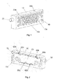
- Fig.1 shows a spatial front view of the clamping device (1) according to the invention for a machine tool in the home position.
- the clamping surface is located on the, the viewer facing side.
- the stop pins (40) protrude out of the clamping surface.
- the basic body (10) has at least one mounting hole (10a) over which the entire clamping device can be attached.
- the guide pins (20a) and (20b) are firmly connected to the base body.
- the fixing elements (60a) to (60d) are used, which in turn are firmly connected to the base body (10).
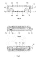
- Fig. 2 a spatial rear view of the clamping device is shown.
- the pressure plate (50) is guided by the guide pins (20a) to (20d), and pushed by the push button (30), when actuated by the operator, along the guideway.
- the cylindrical pin (70) can be seen, which brings the pressure plate (50), on the guideway, back to its original position.
- the cylinder pin (70) is acted upon by a compression spring, which can not be seen in this illustration.
- Fig. 3 shows the clamping surface facing away from the clamping device as a two-dimensional view.
- the pressure plate (50) is in its normal position in which the stop pins (40) are freely movable.
- FIG. 4 shown longitudinal section illustrates the power flow, starting from the push button (30), which is pressed by the operator, via the pressure plate (50) and via the compression spring (80), which presses the cylinder pin (70) against the inside of the base body (10).
- the compression spring (80) is seated in a bore of the pressure plate (50), on whose frontal end, it is supported.
- compression spring (80) and cylinder pin (70) are designed so that they can completely disappear in the largest deflection of the pressure plate (50). Then lies the left in this view body edge of the pressure plate (50) on the inside of the main body (10).
- the stop pins (40) do not rest on the side facing away from the clamping surface, the pressure plate (50). They are thus freely movable and can be optionally pressed by the operator in a position in which they no longer protrude from the clamping surface.
- Figure 5 shows a longitudinal section through the clamping device.
- the guide grooves (50c) and (50d) can be seen, along which the pressure plate (50) is guided over the guide pins (20c) and (20d) fixedly connected to the base body (10).
- the pressure plate (50) is here in its normal position.
- the stop pins (40) protrude out of the clamping surface and can be pushed inwards by the operator.
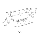
- the pressure plate (50) When pressing the push button, the pressure plate (50) is moved over it along the inclined grooves (50a) to (50d). It describes a running obliquely to the clamping surface web, the surface of the pressure plate (40) always remains parallel to the clamping surface.
- the guide pins (20a) to (20d) can be seen in the respectively provided guide grooves (50a) to (50d) and (60a) to (60d).
- the fixing elements (60a) to (60d) fix because of the better assembly and disassembly of the guide pins (20a) to (20d) in the base body (10).
Landscapes
- Engineering & Computer Science (AREA)
- Mechanical Engineering (AREA)
- Jigs For Machine Tools (AREA)
Abstract
Description
Die vorliegende Erfindung betrifft eine Spannvorrichtung für eine Werkzeugmaschine zum zeitsparenden, lagegenauen und bei Bedarf formschlüssigen Spannen von Werkstücken auf Werkzeugmaschinen.The present invention relates to a clamping device for a machine tool for time-saving, positionally accurate and if necessary positive clamping of workpieces on machine tools.
Ursprünglich wurden zum lagegenauen Spannen von Werkstücken auf Werkzeugmaschinen, zusätzlich gefertigte Bauteile verwendet, die mittels ihrer Kontur bzw. ihrer Baugröße einen Bezug zu der betreffenden Spannvorrichtung herstellten. Dadurch wurde ein vorgegebener Winkel bzw. ein definierter Abstand zu der, dem Werkzeug zugewandten Seite der Spannvorrichtung erreicht.Originally, for the accurate clamping of workpieces on machine tools, additionally manufactured components were used, which produced a reference to the respective clamping device by means of their contour or their size. As a result, a predetermined angle or a defined distance to the tool-facing side of the clamping device has been achieved.
Nachteil dieser Methode, ein Werkstück winkel- und positionsgenau zu spannen, liegt zum Einen in der Gefahr, dass sich Späne und Ablagerungen des Kühlmittels zwischen Spannsystem, zusätzlichem Bauteil und Werkstück ansammeln können, und damit beim Spannen des nächsten Werkstückes, die genaue Lage und Position nicht mehr erreicht werden können. Dies kann lediglich durch sehr sorgfältiges und zeitaufwendiges Reinigen der betreffenden Elemente verhindert werden. Zum Anderen muss jeweils für eine bestimmte Position, bzw. für eine bestimmte Lage des Werkstückes, ein speziell dafür vorgesehener Abstandshalter oder eine eigens dafür angefertigte Winkellehre verwendet werden.Disadvantage of this method to clamp a workpiece angle and exact position, on the one hand in the risk that chips and deposits of coolant between clamping system, additional component and workpiece can accumulate, and thus when clamping the next workpiece, the exact location and position can no longer be achieved. This can be prevented only by very careful and time-consuming cleaning of the elements concerned. On the other hand, for a particular position or for a specific position of the workpiece, a specially provided spacer or a specially prepared angle gauge must be used.
Ein dritter Nachteil dieser Methode, ein Werkstück zu positionieren, liegt in der Anzahl der in einem Fertigungsbetrieb dafür benötigten Einzelteile. Diese müssen jeweils vor dem betreffenden Fertigungsschritt bereitgestellt werden, was zu einem nicht zu vernachlässigbaren Erhöhen der Nebenzeiten führt.A third disadvantage of this method of positioning a workpiece lies in the number of individual parts required in a production plant. These must each be provided before the relevant production step, which leads to a non-negligible increase in non-productive times.
Die genannten Nachteile führten zu Neuentwicklungen bei denen in der Spanneinrichtung des Spannsystems, Stifte bzw. zylindrische Bauteile verwendet werden, auf denen das Werkstück von der Bedienperson aufgesetzt wird. Dazu sind Bohrungen in der Spanneinrichtung auf der dem Werkstückstück zugewandten Seite zur Aufnahme der Stifte vorgesehen, durch deren zylindrische Form das Säubern der Spanneinrichtung wesentlich vereinfacht wird.The disadvantages mentioned led to new developments in which in the clamping device of the clamping system, pins or cylindrical components are used, on which the workpiece is placed by the operator. For this purpose, bores in the clamping device are provided on the workpiece side facing the side for receiving the pins, by the cylindrical shape, the cleaning of the clamping device is substantially simplified.
So sieht die
Nachdem die Stifte von Hand in die Bohrungen gesteckt werden, können sie auch aufgrund der Vibrationen beim Bearbeiten des Werkstückes selbständig herausfallen, und müssen dann wieder aufgesammelt werden.After the pins are manually inserted into the holes, they can also fall out due to the vibrations during machining of the workpiece automatically, and then have to be picked up again.
Die Anordnung der Bohrungen ist dabei so gewählt, dass verschiedenartigste Positioniermöglichkeiten für das Werkstück gegeben sind, wie zum Beispiel in
Eine Möglichkeit, über einen zylinderförmigen oder einen konisch zulaufenden Stift eine Aufnahmeplatte, auf dem eina Werkstück aufgespannt ist, zu positionieren, zeigt die
Der Nachteil dieses Positioniersystems liegt in der Notwendigkeit, ein Druckmedium bereitstellen zu müssen, und über Steuerungselemente die Bewegungen des Positionierstiftes zu koordinieren.The disadvantage of this positioning system is the need to provide a print medium, and to coordinate via controls the movements of the positioning pin.
Eine Weiterentwicklung für das Positionieren von Werkstücken zeigt die
Um möglichst viele verschiedene Werkstückgeometrien abdecken zu können, werden Auflageplatten beschrieben, die Zentrierbohrungen aufweisen, und die zu ihrer Lagefixierung auf die Positionierstifte geschoben werden. Auch hier liegt einer der Nachteile in der Notwendigkeit, ein Druckmedium bereitstellen zu müssen, um die Positionierstifte in Arbeitsstellung bringen zu können. Ein weiterer Nachteil liegt darin, dass aufgrund der freien Beweglichkeit der Positionierstifte bei Nichtbeaufschlagung durch das Druckmedium, diese leicht ungewollt beim Aufschieben der Auflageplatte, wieder in ihre Ausgangsposition zurück geschoben werden.In order to cover as many different workpiece geometries, support plates are described which have center holes, and are pushed to their positional fixation on the positioning pins. Again, one of the disadvantages is the need to provide a print medium to bring the positioning pins into working position. Another disadvantage is that due to the free movement of the positioning pins when not applied by the printing medium, they are easily unintentionally pushed back when pushing the platen back to its original position.
Neben der Lagepositionierung von Werkstücken auf Werkzeugmaschinen geht auch das Umspannen der Werkstücke stark in die unproduktiven Zeiten im Fertigungsprozess mit ein. Deshalb wird häufig versucht, das Werkstück möglichst weit aus dem Schraubstock ragen zu lassen, um damit möglichst selten umspannen zu müssen. Da jedoch das Werkstück im allgemeinen unter Kraft- bzw. Reibschluss gehalten wird, und die Bearbeitungskräfte oft sehr hoch werden, sind hier enge Grenzen gesetzt.In addition to the position positioning of workpieces on machine tools, the re-clamping of the workpieces is also heavily involved in the unproductive times in the manufacturing process. Therefore, it is often attempted to let the workpiece protrude as far as possible from the vise in order to have to re-tighten it as rarely as possible. However, since the workpiece is generally held under force or frictional engagement, and the machining forces are often very high, here are narrow limits.
Der vorliegenden Erfindung liegt somit die Aufgabe zu Grunde, eine anwendungsfreundliche und wiederholgenaue Positioniervorrichtung zu schaffen, zu deren Betrieb kein Zusatzausrüstung benötigt wird, und das wahlweise auch eine formschlüssige Verbindung zum Spannen des Werkstückes zwischen Positioniervorrichtung und Werkstück ermöglicht.The present invention is therefore based on the object to provide an easy-to-use and repeatable positioning, for their operation no additional equipment is needed, and optionally also allows a positive connection for clamping the workpiece between positioning and workpiece.
Gemäß der vorliegenden Erfindung wird diese Aufgabe dadurch gelöst, dass die Spannvorrichtung auf der, dem zu spannenden Werkstück zugewandten Seite, eine Mehrzahl von Anschlagstiften zugeordnet ist, die in entsprechenden Öffnungen des Grundkörpers geführt sind, und je nach Bedarf, aus der Spannfläche herausragen können, oder nicht.According to the present invention, this object is achieved in that the clamping device is assigned to the side facing the workpiece to be clamped, a plurality of stop pins, which are guided in corresponding openings of the body, and can protrude from the clamping surface as needed, or not.
Auf der dem Werkstück abgewandten Seite des Anschlagstiftes ist eine Druckplatte angeordnet, die entlang einer schräg zur Spannfläche verlaufenden Bahn verschiebbar ist.On the side facing away from the workpiece of the stop pin, a pressure plate is arranged, which is displaceable along a path extending obliquely to the clamping surface.
Die Druckplatte, welche zum Verschieben der Anschlagstifte dient, ist entlang einer Führungsnut bzw. einer schräg verlaufenden Bahn verschieblich. Stirnseitig zu der Druckplatte ist dieser ein Druckknopf zugeordnet, über den die Druckplatte entlang der zur Spannfläche schräg verlaufenden Bahn verschoben werden kann.The pressure plate, which serves to displace the stop pins, is displaceable along a guide groove or an inclined path. Front side to the pressure plate of this is associated with a push button over which the pressure plate can be moved along the inclined surface to the clamping surface web.
Am anderen stirnseitigen Ende der Druckplatte befindet sich eine zylinderförmige Vertiefung, in der mindestens eine Druckfeder und mindestens ein Zylinderstift geführt wird.At the other end face of the pressure plate is a cylindrical recess in which at least one compression spring and at least one cylindrical pin is guided.
Drückt die Bedienperson auf den Druckknopf, so wird die Druckplatte entgegen der Federkraft der Druckfeder, entlang der schräg verlaufenden Bahn verschoben. Dabei ist der Winkel zwischen der Spannfläche und der Führungsbahn der Druckplatte so gewählt, daß diese, währenddessen die Führungsstifte bzw. die Anschlagstifte aus ihrer neutralen Position, in die Anschlagsposition bewegt.When the operator presses the push button, the pressure plate is displaced against the spring force of the compression spring along the inclined path. In this case, the angle between the clamping surface and the guide track of the pressure plate is selected so that this, while the guide pins and the stop pins moves from its neutral position, in the stop position.
Anschließend wird die Druckplatte aufgrund der Federkraft der Druckfeder wieder, entlang der schräg verlaufenden Führungsbahn, in ihre Ausgangsposition zurück bewegt.Subsequently, the pressure plate is due to the spring force of the compression spring again, along the inclined guide track, moved back to its original position.
Das Anschlagelement bzw. der Anschlagstift verbleibt in seiner, aus der Spannfläche herausragenden Position, jedoch ohne Zwang in dieser Stellung zu bleiben. Je nach Kontur des Werkstückes kann nun die Bedienperson diejenigen Anschlagstifte in die Spannfläche zurückdrücken, die für die Positionierung des Werkstückes nicht benötigt werden.The stop element or the stop pin remains in its, outstanding from the clamping surface position, but without forcing to remain in this position. Depending on the contour of the workpiece, the operator can now push back those stop pins in the clamping surface, which are not required for the positioning of the workpiece.
Die Bedienperson hat nun die Möglichkeit, mit der einen Hand den Druckknopf zu drücken, und mit der anderen Hand zusätzliche Positionierhilfsmittel auf die Anschlagstifte aufzustecken. Anschließend läßt die Bedienperson den Druckknopf wieder los, und die Druckplatte nimmt ihre ursprüngliche Position wieder ein. Damit können die Anschlagstifte während des Aufsteckens der Positionierhilfsmittel nicht ungewollt hinter die Spannfläche verschoben werden. Ein feinfühliges und damit zeitaufwendiges Handhaben mit der Positioniervorrichtung wird damit verhindert.The operator now has the opportunity to press with one hand the push button, and set up with the other hand additional positioning aids on the stop pins. Then the operator releases the push-button and the pressure plate returns to its original position. Thus, the stop pins during the attachment of the Positioning aids should not be moved unintentionally behind the clamping surface. A sensitive and thus time-consuming handling with the positioning device is thus prevented.
Zusammenfassend wird eine Spannvorrichtung für eine Werkzeugmaschine beschrieben, die eine bewegliche Druckplatte aufweist, die schräg zur Spannfläche geführt wird. Aus der Spannfläche der Positioniervorrichtung kann, je nach Schaltstellung, mindestens ein Anschlagelement bzw. -stift herausragen, an welches das Werkstück anschlägt, bevor es von dem Spannsystem über die Spannfläche fixiert wird. Durch die Bewegung der Druckplatte wird das Anschlagelement bzw. -stift aus seiner Ausgangsposition in die aktive Positionierstellung gebracht.In summary, a clamping device for a machine tool is described, which has a movable pressure plate, which is guided obliquely to the clamping surface. Depending on the switching position, at least one stop element or pin protruding from the clamping surface of the positioning device, against which the workpiece abuts, before it is fixed by the clamping system on the clamping surface. Due to the movement of the pressure plate, the stop element or pin is brought from its initial position into the active positioning position.
Es wird darauf hingewiesen, dass Ausführungsformen der Erfindung mit Bezug auf unterschiedliche Erfindungsgegenstände beschrieben wurden.It should be noted that embodiments of the invention have been described with reference to different subject matters.
Insbesondere sind einige Ausführungsformen der Erfindung mit Vorrichtungsansprüchen und andere Ausführungsformen der Erfindung mit Verfahrensansprüchen beschrieben. Dem Fachmann wird jedoch bei der Lektüre dieser Anmeldung sofort klar werden, dass, sofern nicht explizit anders angegeben, zusätzlich zu einer Kombination von Merkmalen, die zu einem Typ von Erfindungsgegenstand gehören, auch eine beliebige Kombination von Merkmalen möglich ist, die zu unterschiedlichen Typen von Erfindungsgegenständen gehören.In particular, some embodiments of the invention are described with apparatus claims and other embodiments of the invention with method claims. However, it will be readily apparent to those skilled in the art upon reading this application that, unless explicitly stated otherwise, in addition to a combination of features belonging to a type of subject matter, any combination of features that may result in different types of features is also possible Subject matters belong.
Im Folgenden wird die Erfindung anhand des bevorzugten Ausführungsbeispiels näher erläutert. Es zeigen
-
Fig.1 eine dreidimensionale schräge Frontansicht der bevorzugten Ausführungsform der erfindungsgemäßen Spannvorrichtung in Grundstellung. -
Fig.2 eine dreidimensionale schräge Rückansicht der bevorzugten Ausführungsform der erfindungsgemäßen Spannvorrichtung in Grundstellung. -
Fig.3 eine zweidimensionale Rückansicht der bevorzugten Ausführungsform in Grundstellung. -
Fig.4 einen Längsschnitt X-X in Höhe des Druckknopfes und des Zylinderstiftes. -
Fig.5 einen weiteren Längsschnitt C-C, der nahe der unteren Körperkante der Druckplatte verläuft. -
Fig.6 eine Schrägansicht der erfindungsgemäßen Spannvorrichtung, wobei hier wegen der besseren Veranschaulichung verschiedene Komponenten nicht dargestellt wurden.
-
Fig.1 a three-dimensional oblique front view of the preferred embodiment of the clamping device according to the invention in basic position. -
Fig.2 a three-dimensional oblique rear view of the preferred embodiment of the clamping device according to the invention in basic position. -
Figure 3 a two-dimensional rear view of the preferred embodiment in basic position. -
Figure 4 a longitudinal section XX at the level of the push button and the cylinder pin. -
Figure 5 a further longitudinal section CC, which runs near the lower edge of the body of the pressure plate. -
Figure 6 an oblique view of the clamping device according to the invention, wherein various components have not been shown here for better illustration.
Gleiche oder ähnliche Komponenten in unterschiedlichen Figuren sind mit gleichen Bezugsziffern versehen. Die Darstellungen in den Figuren sind schematisch.The same or similar components in different figures are provided with the same reference numerals. The illustrations in the figures are schematic.
Auf der Oberseite des Grundkörpers (10) sind die Führungsstifte (20a) und (20b) mit dem Grundköper fest verbunden. Zu deren Sicherung werden die Fixierelemente (60a) bis (60d) eingesetzt, die ihrerseits mit dem Grundkörper (10) fest verbunden sind.On the upper side of the base body (10), the guide pins (20a) and (20b) are firmly connected to the base body. To secure the fixing elements (60a) to (60d) are used, which in turn are firmly connected to the base body (10).
In
Der in
Dabei sind Druckfeder (80) und Zylinderstift (70) so ausgelegt, daß sie bei der größten Auslenkung der Druckplatte (50) komplett in ihr verschwinden können. Dann liegt die in dieser Ansicht linke Körperkante der Druckplatte (50) an der Innenseite des Grundkörpers (10) an. Die Anschlagstifte (40) liegen nicht an der, der Spannfläche abgewandten Seite, der Druckplatte (50) an. Sie sind dadurch frei beweglich und können wahlweise von der Bedienperson in eine Position gedrückt werden, in der sie nicht mehr aus der Spannfläche herausragen.In this case, compression spring (80) and cylinder pin (70) are designed so that they can completely disappear in the largest deflection of the pressure plate (50). Then lies the left in this view body edge of the pressure plate (50) on the inside of the main body (10). The stop pins (40) do not rest on the side facing away from the clamping surface, the pressure plate (50). They are thus freely movable and can be optionally pressed by the operator in a position in which they no longer protrude from the clamping surface.
Die Druckplatte (50) ist hier in ihrer Grundstellung. Die Anschlagstifte (40) ragen aus der Spannfläche heraus und können von der Bedienperson nach innen geschoben werden.The pressure plate (50) is here in its normal position. The stop pins (40) protrude out of the clamping surface and can be pushed inwards by the operator.
Beim Drücken des Druckknopfes, wird über ihn die Druckplatte (50) entlang der schräg verlaufenden Nuten (50a) bis (50d) bewegt. Sie beschreibt dabei eine schräg zur Spannfläche verlaufende Bahn, wobei die Oberfläche der Druckplatte (40) stets parallel zur Spannfläche bleibt.When pressing the push button, the pressure plate (50) is moved over it along the inclined grooves (50a) to (50d). It describes a running obliquely to the clamping surface web, the surface of the pressure plate (40) always remains parallel to the clamping surface.
Diese Bewegung endet, sobald die Druckplatte (50) auf der Innenseite des Grundkörpers (10) ansteht. In dieser Position ist die Druckfeder (80) maximal eingedrückt. Dadurch wird die Druckplatte (50) wieder in ihre Ausgangsposition zurück bewegt, sobald die Bedienperson keinen Druck mehr auf den Druckknopf ausübt.This movement ends as soon as the pressure plate (50) rests on the inside of the main body (10). In this position, the compression spring (80) is pushed in maximum. As a result, the pressure plate (50) is moved back to its original position as soon as the operator no longer exerts pressure on the push button.
In
Claims (5)
in der taschenförmigen Vertiefung (10c) auf der, der Spannfläche (10b) abgewandten Seite des Grundkörpers (10), mindestens ein Führungsstift (20a) parallel zur Spannfläche (10b), angeordnet ist, der fest mit dem Grundkörper (10) verbunden ist, und eine Druckplatte (50), die auf der, der Spannfläche (10b) abgewandten Seite des Grundkörpers (10), angeordnet ist, und mindestens eine, schräg zur Spannfläche (10b) verlaufende Führungsnut (50a) aufweist, die den Führungsstift (20a) umgreift, und so die Druckplatte (50) entlang der Führungsnut (50a) verschieblich ist.Clamping device for a machine tool, in particular a vise, comprising a base body (10) having a clamping surface (10b) which is penetrated by a plurality of holes, and on which, the clamping surface facing away from, has a pocket-shaped recess (10c), and a plurality of stop pins (40) which are disposed in the bores so that they are displaceable between positions relative to the clamping surface (10b) does not emerge in which the stop pins (40) relative to the clamping surface (10b) emerge or, characterized in that that
in the pocket-shaped depression (10c) on the side of the base body (10) facing away from the clamping surface (10b), at least one guide pin (20a) is arranged parallel to the clamping surface (10b), which is fixedly connected to the base body (10), and a pressure plate (50) which is arranged on the side of the main body (10) facing away from the clamping surface (10b) and has at least one guide groove (50a) running obliquely to the clamping surface (10b), which guides the guide pin (20a). engages, and so the pressure plate (50) along the guide groove (50 a) is displaceable.
die Druckplatte (50) auf einer ihrer stirnseitigen Endflächen (50e), eine zylinderförmige Vertiefung (50.1) aufweist, in der mindestens eine Druckfeder (80) und mindestens ein Zylinderstift (70), angeordnet sind.Clamping device for a machine tool according to claim 1, characterized in that
the pressure plate (50) on one of its front end faces (50e), a cylindrical recess (50.1), in which at least one compression spring (80) and at least one cylindrical pin (70) are arranged.
der Grundkörper (10) mindestens eine stirnseitige, zylinderförmige Öffnung (10c) der taschenförmigen Vertiefung (10c), parallel zur Spannfläche (10b) aufweist.Clamping device for a machine tool according to claim 1, characterized in that
the base body (10) has at least one end-side, cylindrical opening (10c) of the pocket-shaped recess (10c), parallel to the clamping surface (10b).
in der zylinderförmigen Öffnung (10c) ein Druckknopf (30) angeordnet ist, der stirnseitig die Druckplatte (50) berührt und auf der gegenüberliegenden Stirnseite aus dem Grundkörper (10) ragt.Clamping device for a machine tool according to claim 3, characterized in that
in the cylindrical opening (10c), a push button (30) is arranged, the front side of the pressure plate (50) touched and on the opposite end side of the main body (10) protrudes.
jedem Führungsstift (20a) bis (20d) mindestens ein Sicherungselement bzw. ein Fixierelement (60a) bis (60d) zugeordnet ist.Clamping device for a machine tool according to claims 1 and 4, characterized in that
each guide pin (20a) to (20d) is associated with at least one securing element or a fixing element (60a) to (60d).
Applications Claiming Priority (1)
| Application Number | Priority Date | Filing Date | Title |
|---|---|---|---|
| DE102011010726A DE102011010726B3 (en) | 2011-02-09 | 2011-02-09 | Clamping device for a machine tool |
Publications (2)
| Publication Number | Publication Date |
|---|---|
| EP2487009A1 true EP2487009A1 (en) | 2012-08-15 |
| EP2487009B1 EP2487009B1 (en) | 2014-11-05 |
Family
ID=45592192
Family Applications (1)
| Application Number | Title | Priority Date | Filing Date |
|---|---|---|---|
| EP12154452.2A Active EP2487009B1 (en) | 2011-02-09 | 2012-02-08 | Clamping device for a machine tool |
Country Status (2)
| Country | Link |
|---|---|
| EP (1) | EP2487009B1 (en) |
| DE (1) | DE102011010726B3 (en) |
Cited By (1)
| Publication number | Priority date | Publication date | Assignee | Title |
|---|---|---|---|---|
| CN112091643A (en) * | 2020-09-17 | 2020-12-18 | 中国航发贵州黎阳航空动力有限公司 | Degree plate clamp for machining expansion block and machining method of expansion block |
Citations (7)
| Publication number | Priority date | Publication date | Assignee | Title |
|---|---|---|---|---|
| US3463478A (en) | 1964-11-03 | 1969-08-26 | Zip Products Inc | Workpiece positioning device for machine tools |
| US4174828A (en) | 1976-05-10 | 1979-11-20 | Bergman Raymond A | Bayonet clamping apparatus for machine tools |
| WO1992014582A1 (en) | 1991-02-18 | 1992-09-03 | Caesar & Nilsson Ab | Orientating device for vises |
| EP0761382A1 (en) | 1995-09-07 | 1997-03-12 | Günter Lang | Device for positioning pieces in clamping devices |
| US20020089109A1 (en) * | 2001-01-10 | 2002-07-11 | Guimont Thomas R. | Adjustable vise jaw assembly |
| US6799757B1 (en) * | 2002-01-25 | 2004-10-05 | Lang Guenter | Positioning in a retaining device |
| US20090273132A1 (en) * | 2008-05-05 | 2009-11-05 | Parks Daniel C | Pin stop jaw plate |
Family Cites Families (1)
| Publication number | Priority date | Publication date | Assignee | Title |
|---|---|---|---|---|
| DE102009052747A1 (en) * | 2009-11-11 | 2011-05-19 | Sporer, Klaus, Dipl.-Ing. | Positioning device for clamping system, particularly vice, is provided with stop element which is moved relative to clamping area between positions in which stop element emerges relative to clamping surface |
-
2011
- 2011-02-09 DE DE102011010726A patent/DE102011010726B3/en not_active Expired - Fee Related
-
2012
- 2012-02-08 EP EP12154452.2A patent/EP2487009B1/en active Active
Patent Citations (7)
| Publication number | Priority date | Publication date | Assignee | Title |
|---|---|---|---|---|
| US3463478A (en) | 1964-11-03 | 1969-08-26 | Zip Products Inc | Workpiece positioning device for machine tools |
| US4174828A (en) | 1976-05-10 | 1979-11-20 | Bergman Raymond A | Bayonet clamping apparatus for machine tools |
| WO1992014582A1 (en) | 1991-02-18 | 1992-09-03 | Caesar & Nilsson Ab | Orientating device for vises |
| EP0761382A1 (en) | 1995-09-07 | 1997-03-12 | Günter Lang | Device for positioning pieces in clamping devices |
| US20020089109A1 (en) * | 2001-01-10 | 2002-07-11 | Guimont Thomas R. | Adjustable vise jaw assembly |
| US6799757B1 (en) * | 2002-01-25 | 2004-10-05 | Lang Guenter | Positioning in a retaining device |
| US20090273132A1 (en) * | 2008-05-05 | 2009-11-05 | Parks Daniel C | Pin stop jaw plate |
Cited By (1)
| Publication number | Priority date | Publication date | Assignee | Title |
|---|---|---|---|---|
| CN112091643A (en) * | 2020-09-17 | 2020-12-18 | 中国航发贵州黎阳航空动力有限公司 | Degree plate clamp for machining expansion block and machining method of expansion block |
Also Published As
| Publication number | Publication date |
|---|---|
| DE102011010726B3 (en) | 2012-07-12 |
| EP2487009B1 (en) | 2014-11-05 |
Similar Documents
| Publication | Publication Date | Title |
|---|---|---|
| EP2498928B1 (en) | Production system, in particular for free-form bending, having an integrated workpiece and tool manipulator | |
| EP3826814B1 (en) | Panel saw | |
| DE102015120117A1 (en) | WORKPIECE FIXING DEVICE FOR PRESSING MULTIPLE PLACES OF THE WORKPIECE | |
| DE102014007732B4 (en) | Processing unit for a press and centering adapter for a processing unit and method for aligning a Gestelloberteils and a frame base of a processing unit of a press and a processing unit using press | |
| AT509980B1 (en) | MANUFACTURING SYSTEM WITH TOOL MEMORY | |
| DE102019116262A1 (en) | Clamping device and workpiece holding device with one clamping device | |
| EP2658708B1 (en) | Powder press or powder press adapter, and method for operating a powder press | |
| AT519203A1 (en) | Backgauge for a bending machine | |
| DE102008007233A1 (en) | Grinding machine has grinding spindle which has grinding spindle axle adapted for axial tool housing, where integrated coolant distributor is adapted for tool axial change between tool feed position | |
| DE1955193A1 (en) | Method and device for changing tools on a machine with reciprocating working movement | |
| DE2535817C3 (en) | Clamping device on a turret punch | |
| DE202015002566U1 (en) | System for the relative to a press axis centric radial deformation of a workpiece | |
| EP2481492B1 (en) | Bending tool for free-form bending of sheet metal | |
| EP2487009B1 (en) | Clamping device for a machine tool | |
| EP3155366B1 (en) | Calibration tool for an angle measuring tool in a bending die and method for calibrating the angle measuring tool | |
| EP3455041B1 (en) | Hybrid setting unit for breakaway pins or breakaway claws | |
| EP2783795B1 (en) | Clamping jaw | |
| DE10101304A1 (en) | Mother punching device | |
| DE102018003620A1 (en) | Interchangeable tool for a machine tool | |
| DE102009052747A1 (en) | Positioning device for clamping system, particularly vice, is provided with stop element which is moved relative to clamping area between positions in which stop element emerges relative to clamping surface | |
| EP3606688B1 (en) | Exchangeable tool for a machine tool | |
| EP3501736B1 (en) | Pneumatic vice jaw for a vice | |
| DE202012102208U1 (en) | jig | |
| EP3435498B1 (en) | Crimp tool exchange device, crimping press system and method for exchanging a first crimping tool fixed in a process position in a crimping press relative to a second crimping tool | |
| EP3755480B1 (en) | Manufacturing facility with a tool-changing unit and clamping jaw, and method for changing a tool |
Legal Events
| Date | Code | Title | Description |
|---|---|---|---|
| PUAI | Public reference made under article 153(3) epc to a published international application that has entered the european phase |
Free format text: ORIGINAL CODE: 0009012 |
|
| AK | Designated contracting states |
Kind code of ref document: A1 Designated state(s): AL AT BE BG CH CY CZ DE DK EE ES FI FR GB GR HR HU IE IS IT LI LT LU LV MC MK MT NL NO PL PT RO RS SE SI SK SM TR |
|
| AX | Request for extension of the european patent |
Extension state: BA ME |
|
| 17P | Request for examination filed |
Effective date: 20130130 |
|
| GRAP | Despatch of communication of intention to grant a patent |
Free format text: ORIGINAL CODE: EPIDOSNIGR1 |
|
| INTG | Intention to grant announced |
Effective date: 20140602 |
|
| GRAS | Grant fee paid |
Free format text: ORIGINAL CODE: EPIDOSNIGR3 |
|
| GRAA | (expected) grant |
Free format text: ORIGINAL CODE: 0009210 |
|
| AK | Designated contracting states |
Kind code of ref document: B1 Designated state(s): AL AT BE BG CH CY CZ DE DK EE ES FI FR GB GR HR HU IE IS IT LI LT LU LV MC MK MT NL NO PL PT RO RS SE SI SK SM TR |
|
| REG | Reference to a national code |
Ref country code: GB Ref legal event code: FG4D Free format text: NOT ENGLISH |
|
| REG | Reference to a national code |
Ref country code: CH Ref legal event code: EP |
|
| REG | Reference to a national code |
Ref country code: AT Ref legal event code: REF Ref document number: 694342 Country of ref document: AT Kind code of ref document: T Effective date: 20141115 |
|
| REG | Reference to a national code |
Ref country code: IE Ref legal event code: FG4D Free format text: LANGUAGE OF EP DOCUMENT: GERMAN |
|
| REG | Reference to a national code |
Ref country code: DE Ref legal event code: R096 Ref document number: 502012001522 Country of ref document: DE Effective date: 20141224 |
|
| REG | Reference to a national code |
Ref country code: NL Ref legal event code: VDEP Effective date: 20141105 |
|
| REG | Reference to a national code |
Ref country code: LT Ref legal event code: MG4D |
|
| PG25 | Lapsed in a contracting state [announced via postgrant information from national office to epo] |
Ref country code: IS Free format text: LAPSE BECAUSE OF FAILURE TO SUBMIT A TRANSLATION OF THE DESCRIPTION OR TO PAY THE FEE WITHIN THE PRESCRIBED TIME-LIMIT Effective date: 20150305 Ref country code: NO Free format text: LAPSE BECAUSE OF FAILURE TO SUBMIT A TRANSLATION OF THE DESCRIPTION OR TO PAY THE FEE WITHIN THE PRESCRIBED TIME-LIMIT Effective date: 20150205 Ref country code: PT Free format text: LAPSE BECAUSE OF FAILURE TO SUBMIT A TRANSLATION OF THE DESCRIPTION OR TO PAY THE FEE WITHIN THE PRESCRIBED TIME-LIMIT Effective date: 20150305 Ref country code: ES Free format text: LAPSE BECAUSE OF FAILURE TO SUBMIT A TRANSLATION OF THE DESCRIPTION OR TO PAY THE FEE WITHIN THE PRESCRIBED TIME-LIMIT Effective date: 20141105 Ref country code: NL Free format text: LAPSE BECAUSE OF FAILURE TO SUBMIT A TRANSLATION OF THE DESCRIPTION OR TO PAY THE FEE WITHIN THE PRESCRIBED TIME-LIMIT Effective date: 20141105 Ref country code: LT Free format text: LAPSE BECAUSE OF FAILURE TO SUBMIT A TRANSLATION OF THE DESCRIPTION OR TO PAY THE FEE WITHIN THE PRESCRIBED TIME-LIMIT Effective date: 20141105 Ref country code: FI Free format text: LAPSE BECAUSE OF FAILURE TO SUBMIT A TRANSLATION OF THE DESCRIPTION OR TO PAY THE FEE WITHIN THE PRESCRIBED TIME-LIMIT Effective date: 20141105 |
|
| PG25 | Lapsed in a contracting state [announced via postgrant information from national office to epo] |
Ref country code: HR Free format text: LAPSE BECAUSE OF FAILURE TO SUBMIT A TRANSLATION OF THE DESCRIPTION OR TO PAY THE FEE WITHIN THE PRESCRIBED TIME-LIMIT Effective date: 20141105 Ref country code: RS Free format text: LAPSE BECAUSE OF FAILURE TO SUBMIT A TRANSLATION OF THE DESCRIPTION OR TO PAY THE FEE WITHIN THE PRESCRIBED TIME-LIMIT Effective date: 20141105 Ref country code: LV Free format text: LAPSE BECAUSE OF FAILURE TO SUBMIT A TRANSLATION OF THE DESCRIPTION OR TO PAY THE FEE WITHIN THE PRESCRIBED TIME-LIMIT Effective date: 20141105 Ref country code: SE Free format text: LAPSE BECAUSE OF FAILURE TO SUBMIT A TRANSLATION OF THE DESCRIPTION OR TO PAY THE FEE WITHIN THE PRESCRIBED TIME-LIMIT Effective date: 20141105 Ref country code: CY Free format text: LAPSE BECAUSE OF FAILURE TO SUBMIT A TRANSLATION OF THE DESCRIPTION OR TO PAY THE FEE WITHIN THE PRESCRIBED TIME-LIMIT Effective date: 20141105 Ref country code: GR Free format text: LAPSE BECAUSE OF FAILURE TO SUBMIT A TRANSLATION OF THE DESCRIPTION OR TO PAY THE FEE WITHIN THE PRESCRIBED TIME-LIMIT Effective date: 20150206 Ref country code: PL Free format text: LAPSE BECAUSE OF FAILURE TO SUBMIT A TRANSLATION OF THE DESCRIPTION OR TO PAY THE FEE WITHIN THE PRESCRIBED TIME-LIMIT Effective date: 20141105 |
|
| PG25 | Lapsed in a contracting state [announced via postgrant information from national office to epo] |
Ref country code: SK Free format text: LAPSE BECAUSE OF FAILURE TO SUBMIT A TRANSLATION OF THE DESCRIPTION OR TO PAY THE FEE WITHIN THE PRESCRIBED TIME-LIMIT Effective date: 20141105 Ref country code: EE Free format text: LAPSE BECAUSE OF FAILURE TO SUBMIT A TRANSLATION OF THE DESCRIPTION OR TO PAY THE FEE WITHIN THE PRESCRIBED TIME-LIMIT Effective date: 20141105 Ref country code: CZ Free format text: LAPSE BECAUSE OF FAILURE TO SUBMIT A TRANSLATION OF THE DESCRIPTION OR TO PAY THE FEE WITHIN THE PRESCRIBED TIME-LIMIT Effective date: 20141105 Ref country code: DK Free format text: LAPSE BECAUSE OF FAILURE TO SUBMIT A TRANSLATION OF THE DESCRIPTION OR TO PAY THE FEE WITHIN THE PRESCRIBED TIME-LIMIT Effective date: 20141105 |
|
| REG | Reference to a national code |
Ref country code: DE Ref legal event code: R097 Ref document number: 502012001522 Country of ref document: DE |
|
| PLBE | No opposition filed within time limit |
Free format text: ORIGINAL CODE: 0009261 |
|
| STAA | Information on the status of an ep patent application or granted ep patent |
Free format text: STATUS: NO OPPOSITION FILED WITHIN TIME LIMIT |
|
| PG25 | Lapsed in a contracting state [announced via postgrant information from national office to epo] |
Ref country code: LU Free format text: LAPSE BECAUSE OF FAILURE TO SUBMIT A TRANSLATION OF THE DESCRIPTION OR TO PAY THE FEE WITHIN THE PRESCRIBED TIME-LIMIT Effective date: 20150208 |
|
| REG | Reference to a national code |
Ref country code: CH Ref legal event code: PL |
|
| 26N | No opposition filed |
Effective date: 20150806 |
|
| PG25 | Lapsed in a contracting state [announced via postgrant information from national office to epo] |
Ref country code: MC Free format text: LAPSE BECAUSE OF FAILURE TO SUBMIT A TRANSLATION OF THE DESCRIPTION OR TO PAY THE FEE WITHIN THE PRESCRIBED TIME-LIMIT Effective date: 20141105 Ref country code: LI Free format text: LAPSE BECAUSE OF NON-PAYMENT OF DUE FEES Effective date: 20150228 Ref country code: CH Free format text: LAPSE BECAUSE OF NON-PAYMENT OF DUE FEES Effective date: 20150228 |
|
| REG | Reference to a national code |
Ref country code: IE Ref legal event code: MM4A |
|
| REG | Reference to a national code |
Ref country code: FR Ref legal event code: ST Effective date: 20151030 |
|
| PG25 | Lapsed in a contracting state [announced via postgrant information from national office to epo] |
Ref country code: IT Free format text: LAPSE BECAUSE OF FAILURE TO SUBMIT A TRANSLATION OF THE DESCRIPTION OR TO PAY THE FEE WITHIN THE PRESCRIBED TIME-LIMIT Effective date: 20141105 |
|
| PG25 | Lapsed in a contracting state [announced via postgrant information from national office to epo] |
Ref country code: IE Free format text: LAPSE BECAUSE OF NON-PAYMENT OF DUE FEES Effective date: 20150208 |
|
| PG25 | Lapsed in a contracting state [announced via postgrant information from national office to epo] |
Ref country code: SI Free format text: LAPSE BECAUSE OF FAILURE TO SUBMIT A TRANSLATION OF THE DESCRIPTION OR TO PAY THE FEE WITHIN THE PRESCRIBED TIME-LIMIT Effective date: 20141105 Ref country code: FR Free format text: LAPSE BECAUSE OF NON-PAYMENT OF DUE FEES Effective date: 20150302 |
|
| PG25 | Lapsed in a contracting state [announced via postgrant information from national office to epo] |
Ref country code: RO Free format text: LAPSE BECAUSE OF FAILURE TO SUBMIT A TRANSLATION OF THE DESCRIPTION OR TO PAY THE FEE WITHIN THE PRESCRIBED TIME-LIMIT Effective date: 20141105 |
|
| GBPC | Gb: european patent ceased through non-payment of renewal fee |
Effective date: 20160208 |
|
| PG25 | Lapsed in a contracting state [announced via postgrant information from national office to epo] |
Ref country code: MT Free format text: LAPSE BECAUSE OF FAILURE TO SUBMIT A TRANSLATION OF THE DESCRIPTION OR TO PAY THE FEE WITHIN THE PRESCRIBED TIME-LIMIT Effective date: 20141105 |
|
| PG25 | Lapsed in a contracting state [announced via postgrant information from national office to epo] |
Ref country code: GB Free format text: LAPSE BECAUSE OF NON-PAYMENT OF DUE FEES Effective date: 20160208 |
|
| PG25 | Lapsed in a contracting state [announced via postgrant information from national office to epo] |
Ref country code: SM Free format text: LAPSE BECAUSE OF FAILURE TO SUBMIT A TRANSLATION OF THE DESCRIPTION OR TO PAY THE FEE WITHIN THE PRESCRIBED TIME-LIMIT Effective date: 20141105 Ref country code: BG Free format text: LAPSE BECAUSE OF FAILURE TO SUBMIT A TRANSLATION OF THE DESCRIPTION OR TO PAY THE FEE WITHIN THE PRESCRIBED TIME-LIMIT Effective date: 20141105 Ref country code: HU Free format text: LAPSE BECAUSE OF FAILURE TO SUBMIT A TRANSLATION OF THE DESCRIPTION OR TO PAY THE FEE WITHIN THE PRESCRIBED TIME-LIMIT; INVALID AB INITIO Effective date: 20120208 |
|
| PG25 | Lapsed in a contracting state [announced via postgrant information from national office to epo] |
Ref country code: BE Free format text: LAPSE BECAUSE OF NON-PAYMENT OF DUE FEES Effective date: 20150228 |
|
| PG25 | Lapsed in a contracting state [announced via postgrant information from national office to epo] |
Ref country code: TR Free format text: LAPSE BECAUSE OF FAILURE TO SUBMIT A TRANSLATION OF THE DESCRIPTION OR TO PAY THE FEE WITHIN THE PRESCRIBED TIME-LIMIT Effective date: 20141105 |
|
| REG | Reference to a national code |
Ref country code: AT Ref legal event code: MM01 Ref document number: 694342 Country of ref document: AT Kind code of ref document: T Effective date: 20170208 |
|
| PG25 | Lapsed in a contracting state [announced via postgrant information from national office to epo] |
Ref country code: AT Free format text: LAPSE BECAUSE OF NON-PAYMENT OF DUE FEES Effective date: 20170208 |
|
| PG25 | Lapsed in a contracting state [announced via postgrant information from national office to epo] |
Ref country code: MK Free format text: LAPSE BECAUSE OF FAILURE TO SUBMIT A TRANSLATION OF THE DESCRIPTION OR TO PAY THE FEE WITHIN THE PRESCRIBED TIME-LIMIT Effective date: 20141105 |
|
| PG25 | Lapsed in a contracting state [announced via postgrant information from national office to epo] |
Ref country code: AL Free format text: LAPSE BECAUSE OF FAILURE TO SUBMIT A TRANSLATION OF THE DESCRIPTION OR TO PAY THE FEE WITHIN THE PRESCRIBED TIME-LIMIT Effective date: 20141105 |
|
| PGFP | Annual fee paid to national office [announced via postgrant information from national office to epo] |
Ref country code: DE Payment date: 20230213 Year of fee payment: 12 |
|
| P01 | Opt-out of the competence of the unified patent court (upc) registered |
Effective date: 20230525 |