EP2485875B1 - Procédé de diminution de la consommation énergétique d'un robot industriel et système robotique industriel - Google Patents
Procédé de diminution de la consommation énergétique d'un robot industriel et système robotique industriel Download PDFInfo
- Publication number
- EP2485875B1 EP2485875B1 EP10754755.6A EP10754755A EP2485875B1 EP 2485875 B1 EP2485875 B1 EP 2485875B1 EP 10754755 A EP10754755 A EP 10754755A EP 2485875 B1 EP2485875 B1 EP 2485875B1
- Authority
- EP
- European Patent Office
- Prior art keywords
- robot
- energy
- energy consumption
- model
- time
- Prior art date
- Legal status (The legal status is an assumption and is not a legal conclusion. Google has not performed a legal analysis and makes no representation as to the accuracy of the status listed.)
- Not-in-force
Links
Images


Classifications
-
- B—PERFORMING OPERATIONS; TRANSPORTING
- B25—HAND TOOLS; PORTABLE POWER-DRIVEN TOOLS; MANIPULATORS
- B25J—MANIPULATORS; CHAMBERS PROVIDED WITH MANIPULATION DEVICES
- B25J9/00—Programme-controlled manipulators
- B25J9/16—Programme controls
- B25J9/1656—Programme controls characterised by programming, planning systems for manipulators
- B25J9/1664—Programme controls characterised by programming, planning systems for manipulators characterised by motion, path, trajectory planning
-
- G—PHYSICS
- G05—CONTROLLING; REGULATING
- G05B—CONTROL OR REGULATING SYSTEMS IN GENERAL; FUNCTIONAL ELEMENTS OF SUCH SYSTEMS; MONITORING OR TESTING ARRANGEMENTS FOR SUCH SYSTEMS OR ELEMENTS
- G05B2219/00—Program-control systems
- G05B2219/30—Nc systems
- G05B2219/34—Director, elements to supervisory
- G05B2219/34314—Slow down, limit speed for energy saving
-
- G—PHYSICS
- G05—CONTROLLING; REGULATING
- G05B—CONTROL OR REGULATING SYSTEMS IN GENERAL; FUNCTIONAL ELEMENTS OF SUCH SYSTEMS; MONITORING OR TESTING ARRANGEMENTS FOR SUCH SYSTEMS OR ELEMENTS
- G05B2219/00—Program-control systems
- G05B2219/30—Nc systems
- G05B2219/39—Robotics, robotics to robotics hand
- G05B2219/39361—Minimize time-energy cost
-
- G—PHYSICS
- G05—CONTROLLING; REGULATING
- G05B—CONTROL OR REGULATING SYSTEMS IN GENERAL; FUNCTIONAL ELEMENTS OF SUCH SYSTEMS; MONITORING OR TESTING ARRANGEMENTS FOR SUCH SYSTEMS OR ELEMENTS
- G05B2219/00—Program-control systems
- G05B2219/30—Nc systems
- G05B2219/40—Robotics, robotics mapping to robotics vision
- G05B2219/40498—Architecture, integration of planner and motion controller
-
- G—PHYSICS
- G05—CONTROLLING; REGULATING
- G05B—CONTROL OR REGULATING SYSTEMS IN GENERAL; FUNCTIONAL ELEMENTS OF SUCH SYSTEMS; MONITORING OR TESTING ARRANGEMENTS FOR SUCH SYSTEMS OR ELEMENTS
- G05B2219/00—Program-control systems
- G05B2219/30—Nc systems
- G05B2219/40—Robotics, robotics mapping to robotics vision
- G05B2219/40507—Distributed planning, offline trajectory, online motion, avoid collision
-
- G—PHYSICS
- G05—CONTROLLING; REGULATING
- G05B—CONTROL OR REGULATING SYSTEMS IN GENERAL; FUNCTIONAL ELEMENTS OF SUCH SYSTEMS; MONITORING OR TESTING ARRANGEMENTS FOR SUCH SYSTEMS OR ELEMENTS
- G05B2219/00—Program-control systems
- G05B2219/30—Nc systems
- G05B2219/50—Machine tool, machine tool null till machine tool work handling
- G05B2219/50181—After stopping apply additionally a brake
Definitions
- the present invention relates to a method for reducing the energy consumption of an industrial robot configured to carry out work during a work cycle. Further, the present invention relates to an industrial robot system comprising a robot including a manipulator, and program storage for storing a control program defining work to be carried out by the robot during a work cycle.
- An industrial robot is generally used for industrial automation.
- the robot is programmed to follow a movement path while the robot carries out work during a work cycle.
- a robot control program has information about what the robot should do and in which order tasks should be executed along the path.
- the control program comprises a series of robot program instructions written in a robot programming language.
- the control program has information about all target points on the movement path.
- the robot programming could be done online manually by teaching the robot positions and orientations of target points on the movement path.
- the control program could also be created by an offline programming and simulation tool running on an external computer, such as a PC.
- An industrial robot system includes a manipulator having a plurality of arms that are movable relative each other about a plurality of axes and motors for actuating the movements of the axes and a robot controller having means for operating the manipulator.
- the robot controller comprises a storage unit for storing one or more control programs for controlling the movement of the manipulator.
- the control program comprises program instructions, including movement instructions for the manipulator.
- the control program specifies a geometric path to be followed by the robot when carrying out the work.
- the program may also specify limitations on speed and accelerations along the path.
- the geometric path can be expressed in joint angels or in Cartesian coordinates. The relation between the joint angels and the Cartesian coordinates are determined by a kinematic model of the robot.
- the geometric path specifies the positions of the robot, but not the speed.
- the robot controller comprises a program interpreter configured to execute the control program and to provide instructions based on the movement instructions to a path planner.
- the path planner receives the instructions from the program interpreter and on basis thereof determines how the manipulator should move in order to be able to execute the movement instructions.
- the path planner generates a trajectory including a geometric path and a speed profile along the path.
- the path planner plans how the instructed movement should be performed by carrying out an interpolation of the movements.
- the interpolation includes dividing the instructed movement into a plurality of small increments, and computing the joint angles for all axis of the robot for each increment.
- the joint angels are then converted into reference values for the motors.
- the path planner transmits the computed motor references to drive units that control the motors by converting DC current to a variable alternating current in dependence on the motors references.
- cycle time is meant the time it takes for the robot to carry out a work cycle. It is important to make the control program as time optimal as possible in order to reduce the cycle time. Therefore, the normal path planning algorithms are based on a solution to an optimization problem that is defined as minimizing the cycle time subject to customer constraints and robot constraints, where customer constraints could be e.g. speed and acceleration values specified by the user.
- customer constraints could be e.g. speed and acceleration values specified by the user.
- Some examples of robot constraints are maximum gear-box torque, maximum available motor torque, and maximum motor speed. This means that all available motor power is used in every discrete time step as long as no customer or robot constraint is violated.
- Industrial robots are today used throughout almost all branches of industrial applications. As an asset among others, the robots contribute to the total environment impact of the plant, for example, due to its energy consumption.
- the energy consumption for a work cycle is dependent on the movements of the robot, such as the actual path, the velocity, and the acceleration of the robot during the work cycle. Accordingly, there is an aim to reduce the energy consumed by the robot.
- EP1 705 541 shows that it is possible to time optimize a time critical part of a work cycle and to reduce the speed of the robot during a non time critical part of the work cycle, in order to lower the energy consumption.
- the robot is run with as low speed as possible dependent on a determined maximum allowed time period.
- to reduce the speed does not necessarily reduce the energy consumed due to friction and gravity.
- the object of the present invention is to further reduce the energy consumed by the robot when following a specified geometric path.
- Such method comprises:
- the speed profile for the axes of the robot when following the specified geometric path is optimized with regard to minimizing the energy consumption of the robot.
- a speed profile for an axis includes information on the speed of the axis and how the speed changes over time, and accordingly information on the acceleration of the axis.
- the present invention optimizes the speed and acceleration of the manipulator, and not the geometric path.
- the geometric path is fixed, or can be allowed to vary within a mall tolerance interval.
- the present invention is advantageous to use for applications which rely on following a given path, for example, to avoid collisions with fixed obstacles in the robot work space.
- the model for the energy consumption of the robot includes a relation between the energy consumed due to friction and the speed of the axes. There exists a speed where the friction torque is at a minimum. When the speed of the manipulator is lower than the speed where the friction torque is at a minimum, the energy consumption will increase, as shown in figure 3 .
- the time for the robot to carry out the robot movement can be shorter than the maximum allowed time. This possibility is used to further reduce the energy consumed.
- the optimization is carried out with the provision that it is permitted to complete the geometric path in a shorter time than the maximum allowed time, thereby making it possible to lock the axes of the robot when it is in a final position, and then switch off the control of the motors in order to save energy.
- the fact that the energy consumed due to gravity can be significantly reduced when one or more of the axes are locked is considered during the optimization of the robot movements.
- the axes are mechanically locked, for example, by applying the brakes of the robot. Whether or not energy is saved depends on the length of the time period of the stand still. It takes some time to apply and release the brakes and preferably those times are also included in the model. If the time period of the stand still is too short, it is not possible to apply the brakes, or it costs more energy to apply the brakes than is saved.
- the optimization method determines whether or not an axis should be mechanically locked during a standstill in order to reduce the energy consumption.
- the axes can be mechanically locked during a stand still at any time during the energy optimized part of the work cycle, not only in the end of the movement.
- the influence on the energy consumption when locking the axes is always considered during a stand still. This means that for some cases the energy consumption can be further reduced by increasing the speed. Accordingly, a further reduction of the energy consumption can be made.
- the invention makes it possible to command optimization of the movements of the robot during at least a part of the work cycle with regard to minimizing the energy consumption of the robot and a maximum allowed time for carrying out the work.
- the term during at least a part of the work cycle is meant during the whole or during one or more parts of the work cycle.
- the invention is suitable for robot applications for which the time is not critical during at least a part of the work cycle, for instance in applications where the robot is tending a machine and the robot spends a part of the work cycle waiting for the machine to be ready.
- the invention enables saving of energy for such applications.
- the maximum allowed time for carrying out the work is set in dependence on the application, for example, the minimum time the robot has to wait for the machine to be tended.
- the model for the energy consumption includes the time it takes to engage/disengage the mechanical lock of the axes of the manipulator, and is designed to take into consideration the time for the engagement/disengagement of the mechanical lock. Whether or not energy is saved depends on the length of the time period of the stand still. It takes some time to apply and release the brakes and preferably those times are also included in the model. If the time period of the stand still is too short, it is not possible to apply the brakes, or it costs more energy to apply the brakes than is saved.
- movements for the manipulator are determined with regard to minimizing the energy consumption during a part of the work cycle, and movements for the manipulator are determined with regard to minimizing the time it takes for the robot to carry out the work during another part of the work cycle, and that reference values for the motors of the robot are calculated based on the robot movements determined with regard to minimizing the energy consumption of the robot as well as with regard to minimizing the time it takes for the robot to carry out the work.
- This embodiment makes it possible to switch between minimizing the cycle time and minimizing the energy consumption during one work cycle.
- This embodiment is advantageous for applications having one or more time critical parts and one or more non-time critical parts during the work cycle.
- control program includes instructions for switching on and off the minimizing of the energy consumption of the robot during the work cycle. This embodiment makes it possible for a robot programmer to command minimizing of the energy consumption during selected parts of the work cycle.
- the method comprises calculating the energy reduction achieved by determining the movements of the manipulator with regard to minimizing the energy consumption of the robot instead of with regard to minimizing the cycle time, and displaying the calculated energy reduction.
- This embodiment enables a robot operator to view the energy reduction achieved and hopefully to encourage the robot operator to use this function.
- the robot comprises drive units that control the motors by converting DC current to a variable alternating current in dependence on said reference values for the motors, and said model for the energy consumption of the robot includes a model of the energy consumption of mechanical parts of the manipulator, a model of the energy consumption of the motors, and a model of the energy consumption of the drive units.
- Such a robot system comprises:
- the system comprises a time optimization module configured to determine, for at least a part of the work cycle, movements for the manipulator with regard to minimizing the time it takes for the robot to carry out the work based on a dynamic model of the robot, the system is configured to upon command switch between minimizing the time it takes for the robot to carry out the work and minimizing the energy consumption of the robot during one work cycle, and said computing unit is configured to calculate reference values for the motors of the robot based on the robot movements determined with regard to minimizing the energy consumption of the robot as well as with regard to minimizing the time it takes for the robot to carry out the work.
- control program includes instructions for switching between minimizing the time it takes for the robot to carry out the work and minimizing the energy consumption of the robot during the work cycle, and the system is configured to switch between time and energy optimization based on the instructions in the robot program.
- the system comprises an external computer for off-line programming of the robot and a robot controller for controlling the movements of the manipulator, said energy optimization module is configured to generate an energy optimized control program and the energy optimization module is stored on the external computer, and the computing unit for calculate reference values for the motors of the robot is stored on the robot controller.
- This embodiment makes it possible to optimize the control program with regard to minimizing the energy consumption during off-line programming of the robot.
- the output from the off-line programming is an energy optimized control program.
- the system comprises a robot controller including a path planner adapted to determine how the manipulator should move based on the control program, and said energy optimization module and the computing unit are parts of the path planner and are stored on the robot controller.
- the energy optimization of the movements is done in the robot controller during path planning. If the robot program is not programmed off-line it is an advantage from a user's point of view to perform the optimization on the controller instead of on an external computer. A further advantage is that the maximum allowed time can be a variable and, for example, it can depend on an input signal from an external unit. Another advantage with this embodiment is that it is possible to determine the trajectory with a higher accuracy compared to if the energy optimization is performed off-line due to the fact that the path planner determines the path based on small increments.
- the present invention is based upon minimizing the energy consumption, instead of cycle time, and this can be described by the following optimization problem:
- energy optimization is in the following used as an equivalent of energy optimal or energy optimized motion planning, which means that the robot motions are planned in order to minimize the energy consumption.
- the energy optimization can be switched on and off.
- the motion planning is made with regard to minimizing the cycle time.
- the switching on and off of the energy optimization is commanded in the control program, for example by providing program instructions for switching on and off of the energy optimization.
- the energy optimization can be switched on per program, per module, per procedure, or per instruction.
- the following is an example how the energy optimization can be used in program code of a control program.
- the energy optimization is turned on by the command EnergyOptimizationOn and is turned off by the command EnergyOptimizationOff.
- the two instructions EnergyOptimizationOn and EnergyOptimizationOff are included in a sequence of move instructions. EnergyOptimizationOn switches on the energy optimization and the second argument is the maximum time that the motion is allowed to take until the EnergyOptimizationOff instruction is executed.
- the program instructions in between a EnergyOptimizationOn and a EnergyOptimizationOff instructions are referred to as an energy-optimization block.
- the time given by the variable maxMoveTime in the example, can change as a function of other related processes and hence the actual energy saving can be different at each execution of a particular energy-optimization block.
- the command printEnergyReduction initiates calculation of the energy reduction achieved by energy optimization instead of optimization of the cycle time, and displaying the calculated energy reduction.
- An important part of the optimization concept is to make it possible to apply a mechanical lock to the axis of the manipulator" such as the brakes of the robot, in the final position and then switch off the control of the motors in order to save energy.
- the brakes When the time specified in the EnergyoptimizationOn instruction is reached the brakes must already be released and the motors must be in controlled mode, in order to be responsive and be able to directly move at the next instruction after the energy-optimization block.
- case 1 and case 2 are combined so that a geometric path is given where the robot can deviate from the path to some specified limit when it reduces the total energy consumption.
- the optimization algorithm can be executed at different levels
- level 1 and 2a The different versions of the solution will be described in detail later.
- the solution is similar in level 1 and 2a.
- the major difference between the different levels is the requirements on the computational complexity.
- level 1 and to some extend level 2a there are not many restrictions on the computational complexity while level 2b put very hard restrictions on the computational complexity since the optimization must be solved while the robot moves and with the limited computer resources available in the robot controller.
- the motion data is not allowed to change when the block is executed. No conditions, i.e. if-statements or loops, which can affect the path, are allowed.
- the geometry of the path within the block has to be decided.
- level 1 The important difference between level 1 and level 2, using model based optimization, is that in the execution at level 1 no data can be changed at the execution of the program while at level 2, motion data can change until the energy-optimization block is entered.
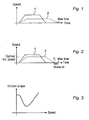
- Figure 1 shows a time-optimized speed profile 1 together with and an energy-optimized speed profile 2 for a robot axis moving without being affected by gravity.
- the energy-optimized speed profile makes the robot reach the final point exactly at a specified maximum time.
- Figure 3 shows a typical friction behavior with static friction, stiction, Coulomb and viscous friction.
- the power produced is proportional to the torque square and therefore friction plays an important role for the energy consumption of the robot.
- a typical friction behavior is shown and obviously there exists a speed where the friction torque is at a minimum and hence it will result in a different speed profile compared to figure 1 if the energy optimization is done with regard to friction.
- Figure 2 shows the time-optimized speed profile 1 of figure 1 together with an energy-optimized speed profile 3 determined with regard to friction.
- the resulting energy-optimized speed profile gives a higher acceleration and speed compared to the profile shown in figure 1 but still lower acceleration and speed compared to the time optimal profile.
- the energy-optimized speed profile 3 shows a motion that reaches the final position at a point in time T r that is before Max time. In the time from T r to Max time the mechanical brakes can be activated and hence no energy is consumed by the mechanical system during this time, which further reduces the total energy consumption.
- the energy-optimized solution has to consider this energy as well and minimize the wasted kinetic energy, in practice this will imply to reduce the speed, leading to the solution in figure 2 .
- the resulting maximum speed will therefore be a trade-off between minimizing the wasted kinetic energy and minimizing the friction losses.
- the total reduction of energy can be computed by evaluating the optimization criterion for the time optimal trajectory and compare this with what is achieved in the energy optimal trajectory. The total reduction of energy is displayed.
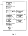
- Figure 4 shows an example of a prior art robot system including a manipulator 8 having a plurality of arms that are movable relative each other about a plurality of axes and motors for actuating the movements of the axes, and a robot controller 9 for controlling the movements of the manipulator.
- the robot controller 9 includes program storage 10 for storing one or more control programs defining work to be carried out by the robot during a work cycle, and a program interpreter 12 configured to execute the control program.
- the robot controller 9 further includes a path planner that receives the instructions from the program interpreter and on basis thereof determines how the manipulator should move in order to be able to execute the movement instructions.
- the path planner generates a trajectory including a geometric path and a speed profile along the path.
- the path planner comprises a geometric path planner 14 configured to plan a geometric path, i.e. the positions of the path, and a dynamic optimization planner 16 configured to plan the speed profile for the path with regard to minimizing the cycle time.
- the dynamic optimization planner 16 uses algorithms that are based on a solution to an optimization problem that is defined as minimizing the cycle time with subject to customer constraints and robot constraints.
- the controller 9 further comprises data storage 18,19,20 storing a robot kinematic model, a robot dynamic model and a drive system model. From the control program a geometric path is created using the robot kinematic model.
- the dynamic optimization planner uses the geometric path to create a time optimal speed profile using a dynamic model of the robot and a model of the robot drive system.
- the path planner further comprises a computing unit 21 configured to calculate reference values for the motors of the robot based on the determined path and speed profile.
- the computing unit 21 carries out an interpolation of the generated trajectory.
- the interpolation includes dividing the trajectory into a plurality of small increments, and computing the joint angles for all axis of the robot for each increment. The joint angels are then converted into reference values for the motors.
- the computing unit 21 transmits the computed motor references to the drive system 22 of the robot controller.
- the drive system includes drive units that control the motors by converting DC current to a variable alternating current in dependence on the motors references.
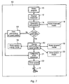
- Figure 5 shows an example of a robot system according to the invention.
- a new additional condition is introduced to differentiate the trajectory generation in the traditional time optimized case from the new energy optimized case.
- Figure 5 it is shown how the overall structure has to be modified in order to introduce the energy optimized trajectory generation in parallel with the present time optimized trajectory generation.
- the program interpreter detects whether energy optimization is commanded on or off.
- the energy optimization is, for example, turned on by the command EnergyOptimizationOn and is turned off by the command EnergyOptimizationOff enclosed in the control program. Energy optimization can be turned on and off several times during a work cycle. If energy optimization is turned off, the time optimized trajectory generation 30 is carried out for the motion instructions.
- the time optimized trajectory generation 30 determines time optimal movements for the robot and includes the steps of generating a geometric path based on a robot kinematic model and generating a time optimal speed profile based on a robot dynamic model and a drive system model. Input to the time optimization is a motion instruction.
- the energy optimization is carried out on the program instructions in between the EnergyOptimizationOn and the EnergyOptimizationOff instructions, also called a program block.
- Input to the energy optimization is a program block and a maximum time for carrying out the block.
- the energy optimization is carried out based on all motion instructions in the program block and the maximum time for the block.
- the energy optimal trajectory generation determines energy optimized movements for the robot and includes the steps of generating a geometric path based on the robot kinematic model and an energy optimal speed profile based on a robot system energy model, the robot dynamic model, and the drive system model.
- the energy optimized movements for the robot is generated based on a maximum allowed time, such as maxMoveTime described above, for carrying out the movements, and robot and customary constrains.
- a maximum allowed time such as maxMoveTime described above
- an energy optimized geometric path is generated as well as an energy optimized speed profile.
- the robot system comprises a time optimization module 30 configured to carry out the time optimized trajectory generation and an energy optimization module 32 configured to carry out the energy optimized trajectory generation.
- the robot system comprises data storage 34 for storing the robot system energy model.
- the robot system energy model is a model of the energy consumption of the robot system in dependence on the movements of the axes of the robot.
- the robot system comprises a robot controller including a computing unit 21 configured to calculate reference values for the motors of the robot based on the determined movements.
- Optimization of the movements of the robot with regard to minimizing the energy consumption of the robot means that the movements of the robot are determined with the aim of minimizing the energy consumption. Different degrees of reduction of the consumed energy can be achieved in dependence on how sophisticated the energy model is.
- the time optimal trajectory generation and the energy optimal trajectory generation can be done off-line on an external computer during programming of the robot, or in the robot controller during programming of the robot or during execution of the control program. Irrespective of whether the energy optimization is done on the controller or on an external computer, the computing of motor references is always done on the robot controller.
- level 1 i.e. off-line energy optimization
- the energy optimization is done off-line at an external computer 40, for example during off-line programming of the robot.
- Input at this level is a robot control program while the output is a new energy optimized control program including energy optimized robot move instructions.
- For program instructions where energy optimization is off no change is made to the program instructions.
- energy optimization is on energy optimization is carried out on the program instructions in between the EnergyOptimizationOn and the EnergyOptimizationOff instruction, also called a program block.
- Output from the energy optimization is an energy optimized program block.
- the program block includes move instructions, and the energy optimized program block includes energy optimized program instructions.
- an instruction to engage/disengage the brakes can be inserted in the program.
- the energy optimized program can have the same path geometry as the original program if case 1 of the energy optimization is used or a modified geometry if case 2 or a combination of case 1 and case 2 is used.
- the offline energy optimization module takes a robot program as input and makes an energy optimization of the part of the program where the energy optimization is activated. Output from the energy optimization module is a new energy optimized robot program or part of a program.
- the path planner generates a motor references based on the movement instructions in the control program.
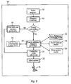
- Figure 7 shows a robot controller 50 including an energy optimization that only optimizes the speed profile and the brake engage/disengage time instances but not the geometric path.
- the robot move instructions of the control program specify the geometry of the robot motion while the speed profile and the brake engage/disengage time instances are optimized to achieve minimal energy consumption.
- the path planner includes a geometric path planner 14 that generates a geometric path based on the move instructions in the control program and a robot kinematic model.
- the path planner also includes an energy optimization module 52 configured to generate an energy optimized speed profile based on the geometric path description, the robot dynamic model, the model of the drive system and the robot system energy model.
- the path planner also includes a time optimization module 53 configured to generate a time optimized speed profile based on the robot dynamic model and the drive system model. If energy optimization is turned on the energy optimization module 52 is used for generating the speed profile and brake engage/disengage time instances while if energy optimization is turned off, the time optimization module is used for generating the speed profile.
- Figure 8 shows a robot controller 54 including a path planner 56 adapted to generate an energy optimized trajectory.
- the generation of the energy optimized trajectory includes determining an energy optimized geometric path as well as an energy optimized speed profile. In this case the geometry of the path is free to decide in the energy optimization.
- the robot program provides the start and end robot configuration, next the energy trajectory optimization finds an energy optimal path and speed profile for the robot.
- the optimization utilizes the robot kinematic model, the dynamic model, the drive system model, and finally the robot system energy model, to solve for the energy optimal trajectory.
- case 1 and case 2 of the optimization principle can be described as in figure 7 and 8 .
- the geometry is still generated by the geometric path planner using the robot kinematic model while the time optimization is replaced by the energy optimization which utilizes the robot dynamic model, the drive system model and the robot system energy model.
- the resulting motor reference is fed down to the drive system 22 as a reference for the motors of the robot manipulator 8.
- figure 8 also the geometry is a free parameter for the energy optimization to decide.
- the geometric path planner is now a part of the energy-optimization block 56 and input to this block is a robot program, output is a reference to the drive system.
- the energy optimization utilizes in case 2, the robot kinematic model, the robot dynamic model, the drive system model, and finally the robot system energy model.
- the energy model is a model of the energy consumption of the complete robot system; this includes the mechanical manipulator, the electric motors and the electric drive system. It could also take into account other resources in the system such as fans and processors that can be switched on and off or be controlled depending on the current status of the system.
- Figure 9 a block diagram for the energy model is shown.
- the model includes a mechanical model, an electric drive system model, a motor model, and a controller hardware model. Further, the model includes an environmental model, for example, the surrounding temperature can be measured and used as an input to calculations of the friction.
- the mechanical model contains the robot dynamic model including friction model.
- the mechanical model in the energy model could have a more sophisticated friction model than the prior art mechanical models.
- the electric drive system model and the motor model are extensions to the drive system model which could include the energy flow (reuse of energy) between motors at acceleration/deceleration.
- An energy dissipation model is also included in the electric motor model, this model include friction in the motor but also the actual efficiency of the motor.
- the controller hardware model is a model of the energy consumption in the controller hardware, such as fans, CPU-boards, etc.
- the model also includes a model of the brakes; engage/disengage times as well as power consumption in engaged and disengaged mode.
- Figure 10 shows a simplified robot with only one rotational joint and illustration of two domains, electrical and mechanical.
- the use of an optional arm is also illustrated and with this option the example becomes the same as the motion of a robot (axis 3 of an articulated 6-DOF robot for example).
- the friction can be described as
- Input to the model is the joint acceleration a i .
- the joint speed and position can be computed from a i by simple integration.
- no model of the controller hardware energy consumption is included.
- the brake engagement/disengagement time is here assumed to be zero.
- ⁇ t can be fixed or computed from q ⁇ ( t i ) , q ( t i +1 ) and a i is the acceleration value used in the time interval t i to t i+1 .
- the discrete optimization problem is formulated with a number of constraints, for example on the torque, the joint speed, and the joint acceleration.
- the motor model and the electric motor drive system are combined using the assumption that the current controller is significantly faster than the optimization time step.
- the torque is given by the system equation in (1).
- the constraints include maximum and minimum values on the torques and acceleration as well as boundary conditions on the angular position and angular velocity. The normal case would be that the angular speed is zero at the start time (to) and zero at the end time (t N ) but other values could also be included as well as constraints on the angular acceleration (start, end, and max/min values).
- the delta time is assumed to be fixed to a sampling time ⁇ t and the smaller this value the closer the solution comes to the true continuous optimum.
- the optimization problem can be solved using a standard general non-linear optimization algorithm, see for example Jorge Nocedal and Stephen J. Wright. Numerical Optimization, Springer. Series in Operations Research, 1999, ISBN 0-387-98793-2 , and R. Fletcher. Practical Methods of Optimization. 1987. ISBN 0-471-91547-5 .
- the motion of a robot with two or more degrees-of-freedom (DOF) robot is optimized with respect to the energy consumption.
- the optimization can be made according to the cases described previously, i.e.,
- both cases of the problem can be formulated in a similar way as in (4).
- case 1 the geometry of the path is given and the optimization problem is to find a (scalar) speed profile along the geometry that minimizes the energy and brake engagement/disengagement time instances for each axis.
- case 2 the geometry is not specified, except for the start and the end position. This case is similar to (4) where only the start and end point are specified and the acceleration is a free parameter.
- the a i parameters are no longer scalars, instead each a i is a vector with the length equal to the number of actuated degrees-of-freedom of the considered robot.
- the optimization problem can still be formulated in a similar way as in (4) but some inequalities now become vector inequalities.
- the number of variables and the complexity of the solution grow also significantly with the increased number of degrees-of-freedom.
- the energy optimization could be turned on and off by a signal from an external unit, such as a PLC.
Claims (12)
- Procédé de réduction de la consommation d'énergie d'un robot industriel configuré pour effectuer du travail pendant un cycle de travail et comprenant un manipulateur ayant une pluralité de bras qui sont mobiles l'un par rapport à l' autre autour d'une pluralité d'axes et des moteurs pour actionner les mouvements des axes, procédé dans lequel :- on définit un modèle pour la consommation d'énergie du robot en fonction des mouvements des axes du robot, comprenant une relation entre l'énergie consommée due au frottement et la vitesse des axes et l'énergie consommée due à la force de gravité agissant sur les bras,- on mémorise un programme de commande précisant un trajet géométrique à suivre par le robot lorsqu'il est effectue le travail, et- on détermine des mouvements du robot pendant au moins une partie du cycle de travail en vue de minimiser la consommation d'énergie du robot sur la base du programme de commande et du modèle pour la consommation d'énergie du robot, et- on calcule des valeurs de référence pour les moteurs du robot sur la base des mouvements déterminés du robot, caractérisé en ce que- le modèle pour la consommation d'énergie est conçu pour considérer le fait que l'énergie consommée due à la force de gravité agissant sur les bras peut être réduite pendant l'arrêt d'un ou de plusieurs des axes si les axes sont verrouillés mécaniquement, et- la détermination des mouvements du robot comprend calculer des profils de vitesse pour les axes du robot lorsque l'on suit le trajet géométrique précisé et déterminer si ou non un axe doit être verrouillé mécaniquement pendant un arrêt de l'axe afin de réduire la consommation d'énergie sur la base du modèle pour la consommation d'énergie du robot et un temps maximum alloué pour effectuer le mouvement du robot pendant cette partie du cycle de travail, pourvu qu'il soit permis de compléter le trajet géométrique en un temps plus court qu'un temps alloué maximum.
- Procédé suivant la revendication 1, dans lequel le modèle pour la consommation d'énergie est conçu pour prendre en considération le temps de verrouillage/déverouillage du verrou mécanique.
- Procédé suivant la revendication 1 ou 2, dans lequel les axes sont verrouillés mécaniquement en appliquant des freins au moteur du robot.
- Procédé suivant l'une quelconque des revendications précédentes, dans lequel des mouvements du manipulateur sont déterminés au regard de la minimisation de la consommation d'énergie pendant une partie du cycle de travail et des mouvements pour le manipulateur sont déterminés en regard de la minimisation du temps qu'il faut pour que le robot effectue le travail pendant une autre partie du cycle de travail et en ce que des valeurs de référence pour des moteurs du robot sont calculées sur la base des mouvements du robot déterminés en regard de la minimisation de la consommation d'énergie du robot ainsi qu'en regard de la minimisation du temps qu'il faut pour que le robot effectue le travail.
- Procédé suivant l'une quelconque des revendications précédentes, dans lequel le programme de commande comprend des instructions pour brancher et débrancher la minimisation de la consommation d'énergie du robot pendant le cycle de travail.
- Procédé suivant l'une quelconque des revendications précédentes, dans lequel le procédé comprend :- calculer la réduction d'énergie obtenue en déterminant les mouvements du manipulateur en regard de la minimisation de la consommation d'énergie du robot au lieu que se soit en regard de la minimisation du temps de cycle, et- afficher la réduction d'énergie calculée.
- Procédé suivant l'une quelconque des revendications précédentes, dans lequel le robot comprend des unités d'entraînement, qui commande des moteurs en transformant du courant continu en un courant alternatif variable en fonction des valeurs de référence pour les moteurs et le modèle de la consommation d'énergie du robot comprend un modèle de la consommation d'énergie de parties mécaniques du manipulateur, un modèle de la consommation d'énergie des moteurs et un modèle de la consommation d'énergie des unités d'entraînement.
- Système de robot industriel comprenant un robot comprenant un manipulateur (8) ayant une pluralité de bras qui sont mobiles les uns par rapport aux autres autour d'une pluralité d'axes et des moteurs pour actionner les mouvements des axes et une mémoire (10) de programme pour mémoriser un programme de commande précisant un trajet géométrique à suivre par le robot lorsqu'il effectue le travail pendant un cycle de travail,- une mémoire (34) de données mémorisant un modèle pour la consommation d'énergie du robot en fonction du mouvement des axes de robot, le modèle comprenant une relation entre l'énergie consommée due au frottement et à la vitesse des axes et l'énergie consommée due à la force de gravité agissant sur les bras, et- un module (32) d'optimisation d'énergie, configuré pour déterminer pour au moins une partie du cycle de travail des mouvements du manipulateur en regard de la minimisation de la consommation d'énergie du robot sur la base du programme de commande et du modèle pour la consommation d'énergie du robot, et- une unité (21) informatique configurée pour calculer des valeurs de référence pour les moteurs du robot sur la base des mouvements déterminée du robot, caractérisé en ce que la mémoire de données est conçue pour mémoriser un modèle pour l'énergie, conçu pour considérer le fait que l'énergie consommée due à la force de gravité agissant sur les bras peut être réduite pendant un arrêt d'un ou de plusieurs des axes si les axes sont verrouillés mécaniquement, et- le module d'optimisation d'énergie est configuré pour calculer les profils de vitesse pour les axes du robot lorsque l'on suit le trajet géométrique précisé et pour déterminer si ou non un axe doit être verrouillé mécaniquement pendant un arrêt afin de réduire la consommation d'énergie, sur la base de ce modèle pour la consommation d'énergie du robot, et un temps maximum alloué pour effectuer le mouvement du robot pendant cette partie du cycle de travail, pourvu qu'il soit permis d'achever le trajet géométrique en un temps plus court que le temps maximum alloué.
- Système de robot suivant la revendication 8, dans lequel le système comprend un module (30) d'optimisation du temps, configuré pour déterminer, pour au moins une partie du cycle de travail, des mouvements pour le manipulateur en regard de la minimisation du temps qu'il faut pour que le robot effectue le travail sur la base d'un modèle dynamique du robot, le système est configuré pour, sur instruction, commuter entre minimiser le temps qu'il faut pour que le robot effectue le travail et minimiser la consommation d'énergie du robot pendant un cycle de travail, et l'unité informatique est configurée pour calculer les valeurs de référence pour les moteurs du robot sur la base des mouvements du robot déterminés en regard de la minimisation de la consommation d'énergie du robot, ainsi qu'en regard de la minimisation du temps qu'il faut pour que le robot effectue le travail.
- Système de robot suivant la revendication 9, dans lequel le programme de commande comprend des instructions pour commuter entre minimiser le temps qu'il faut pour que le robot effectue le travail et minimiser la consommation d'énergie du robot pendant le cycle de travail et le système est configuré pour commuter entre l'optimisation de temps et l'optimisation d'énergie sur la base des instructions du programme du robot.
- Système de robot suivant l'une quelconque des revendications 8 à 10, dans lequel le système comprend un ordinateur (40) extérieur pour la programmation hors ligne du robot et une unité (50, 54) de commande du robot pour commander les mouvements du manipulateur, le module (32) d'optimisation d'énergie étant configuré pour produire un programme de commande optimisé d'énergie, le module d'optimisation d'énergie étant mémorisé sur l'ordinateur extérieur et l'unité (21) informatique étant mémorisée sur l'unité de commande du robot.
- Système de robot suivant l'une quelconque des revendications 8 à 11, dans lequel le système comprend une unité (50, 54) de commande du robot, comprenant un planificateur de trajet conçu pour déterminer comment le manipulateur doit se déplacer sur la base du programme de commande et le module (32) d'optimisation d'énergie et l'unité (21) informatique font partis du planificateur du trajet.
Priority Applications (1)
| Application Number | Priority Date | Filing Date | Title |
|---|---|---|---|
| EP10754755.6A EP2485875B1 (fr) | 2009-10-06 | 2010-09-20 | Procédé de diminution de la consommation énergétique d'un robot industriel et système robotique industriel |
Applications Claiming Priority (3)
| Application Number | Priority Date | Filing Date | Title |
|---|---|---|---|
| PCT/EP2009/062961 WO2011042049A1 (fr) | 2009-10-06 | 2009-10-06 | Procédé de réduction de la consommation d'énergie d'un robot industriel et système de robot industriel |
| PCT/EP2010/063783 WO2011042293A1 (fr) | 2009-10-06 | 2010-09-20 | Procédé de diminution de la consommation énergétique d'un robot industriel et système robotique industriel |
| EP10754755.6A EP2485875B1 (fr) | 2009-10-06 | 2010-09-20 | Procédé de diminution de la consommation énergétique d'un robot industriel et système robotique industriel |
Publications (2)
| Publication Number | Publication Date |
|---|---|
| EP2485875A1 EP2485875A1 (fr) | 2012-08-15 |
| EP2485875B1 true EP2485875B1 (fr) | 2013-04-24 |
Family
ID=46465347
Family Applications (1)
| Application Number | Title | Priority Date | Filing Date |
|---|---|---|---|
| EP10754755.6A Not-in-force EP2485875B1 (fr) | 2009-10-06 | 2010-09-20 | Procédé de diminution de la consommation énergétique d'un robot industriel et système robotique industriel |
Country Status (1)
| Country | Link |
|---|---|
| EP (1) | EP2485875B1 (fr) |
Cited By (12)
| Publication number | Priority date | Publication date | Assignee | Title |
|---|---|---|---|---|
| DE102013013847A1 (de) * | 2013-08-20 | 2015-02-26 | Kuka Roboter Gmbh | Energieoptimales Konfigurieren eines Manipulators |
| DE102014202755A1 (de) * | 2014-02-14 | 2015-08-20 | Carl Zeiss Smt Gmbh | Verfahren zur Verlagerung mindestens eines optischen Bauelements |
| US9298863B2 (en) | 2014-07-31 | 2016-03-29 | Siemens Industry Software Ltd. | Method and apparatus for saving energy and reducing cycle time by using optimal robotic joint configurations |
| DE102015211865B3 (de) * | 2015-06-25 | 2016-05-12 | Kuka Roboter Gmbh | Verfahren zum redundanzoptimierten Planen eines Betriebs eines mobilen Roboters |
| DE102014225252A1 (de) | 2014-12-09 | 2016-06-09 | Kuka Systems Gmbh | Verfahren zum Überwachen wenigstens eines Industrieroboters, Industrieroboter und System mit mehreren Industrierobotern |
| US9457469B2 (en) | 2014-08-14 | 2016-10-04 | Siemens Industry Software Ltd. | Method and apparatus for automatic and efficient location generation for cooperative motion |
| US9469029B2 (en) | 2014-07-31 | 2016-10-18 | Siemens Industry Software Ltd. | Method and apparatus for saving energy and reducing cycle time by optimal ordering of the industrial robotic path |
| US9649765B2 (en) | 2013-03-11 | 2017-05-16 | Siemens Aktiengesellschaft | Reducing energy consumption of industrial robots by using new methods for motion path programming |
| US9701011B2 (en) | 2014-05-08 | 2017-07-11 | Siemens Industry Software Ltd. | Method for robotic energy saving tool search |
| US9815201B2 (en) | 2014-07-31 | 2017-11-14 | Siemens Industry Software Limited | Method and apparatus for industrial robotic energy saving optimization using fly-by |
| US9922144B2 (en) | 2014-03-26 | 2018-03-20 | Siemens Industry Software Ltd. | Energy and cycle time efficiency based method for robot positioning |
| EP3907042A1 (fr) * | 2020-05-06 | 2021-11-10 | Eagle Technology, LLC | Augmentation de la résistance de manipulateur dynamique |
Families Citing this family (3)
| Publication number | Priority date | Publication date | Assignee | Title |
|---|---|---|---|---|
| CN113021334B (zh) * | 2019-12-25 | 2022-09-30 | 广东省智能制造研究所 | 一种能量最优的机器人控制方法 |
| DE102021125628B3 (de) * | 2021-10-04 | 2022-10-13 | Physik Instrumente (PI) GmbH & Co KG | Geschwindigkeitsvorgaben zur Trajektorienbestimmung von Kinematiken |
| CN117444985B (zh) * | 2023-12-20 | 2024-03-12 | 安徽大学 | 一种机械臂小车控制方法及系统 |
-
2010
- 2010-09-20 EP EP10754755.6A patent/EP2485875B1/fr not_active Not-in-force
Cited By (15)
| Publication number | Priority date | Publication date | Assignee | Title |
|---|---|---|---|---|
| US9649765B2 (en) | 2013-03-11 | 2017-05-16 | Siemens Aktiengesellschaft | Reducing energy consumption of industrial robots by using new methods for motion path programming |
| DE102013013847A1 (de) * | 2013-08-20 | 2015-02-26 | Kuka Roboter Gmbh | Energieoptimales Konfigurieren eines Manipulators |
| DE102014202755A1 (de) * | 2014-02-14 | 2015-08-20 | Carl Zeiss Smt Gmbh | Verfahren zur Verlagerung mindestens eines optischen Bauelements |
| US9851554B2 (en) | 2014-02-14 | 2017-12-26 | Carl Zeiss Smt Gmbh | Method for displacing at least one optical component |
| US9922144B2 (en) | 2014-03-26 | 2018-03-20 | Siemens Industry Software Ltd. | Energy and cycle time efficiency based method for robot positioning |
| US9701011B2 (en) | 2014-05-08 | 2017-07-11 | Siemens Industry Software Ltd. | Method for robotic energy saving tool search |
| US9815201B2 (en) | 2014-07-31 | 2017-11-14 | Siemens Industry Software Limited | Method and apparatus for industrial robotic energy saving optimization using fly-by |
| US9469029B2 (en) | 2014-07-31 | 2016-10-18 | Siemens Industry Software Ltd. | Method and apparatus for saving energy and reducing cycle time by optimal ordering of the industrial robotic path |
| US9298863B2 (en) | 2014-07-31 | 2016-03-29 | Siemens Industry Software Ltd. | Method and apparatus for saving energy and reducing cycle time by using optimal robotic joint configurations |
| US9457469B2 (en) | 2014-08-14 | 2016-10-04 | Siemens Industry Software Ltd. | Method and apparatus for automatic and efficient location generation for cooperative motion |
| DE102014225252A1 (de) | 2014-12-09 | 2016-06-09 | Kuka Systems Gmbh | Verfahren zum Überwachen wenigstens eines Industrieroboters, Industrieroboter und System mit mehreren Industrierobotern |
| DE102015211865B3 (de) * | 2015-06-25 | 2016-05-12 | Kuka Roboter Gmbh | Verfahren zum redundanzoptimierten Planen eines Betriebs eines mobilen Roboters |
| US10828777B2 (en) | 2015-06-25 | 2020-11-10 | Kuka Deutschland Gmbh | Method for the redundancy-optimized planning of the operation of a mobile robot |
| EP3907042A1 (fr) * | 2020-05-06 | 2021-11-10 | Eagle Technology, LLC | Augmentation de la résistance de manipulateur dynamique |
| US11633853B2 (en) | 2020-05-06 | 2023-04-25 | Eagle Technology, Llc | Dynamic manipulator strength augmentation |
Also Published As
| Publication number | Publication date |
|---|---|
| EP2485875A1 (fr) | 2012-08-15 |
Similar Documents
| Publication | Publication Date | Title |
|---|---|---|
| EP2485875B1 (fr) | Procédé de diminution de la consommation énergétique d'un robot industriel et système robotique industriel | |
| WO2011042293A1 (fr) | Procédé de diminution de la consommation énergétique d'un robot industriel et système robotique industriel | |
| Gasparetto et al. | Path planning and trajectory planning algorithms: A general overview | |
| US20230373089A1 (en) | Method for controlling robot, robot and computer-readable storage medium | |
| Debrouwere et al. | Time-optimal path following for robots with convex–concave constraints using sequential convex programming | |
| Fang et al. | An approach for jerk-continuous trajectory generation of robotic manipulators with kinematical constraints | |
| Kröger et al. | Literature survey: Trajectory generation in and control of robotic systems | |
| Lu et al. | Time-optimal tool motion planning with tool-tip kinematic constraints for robotic machining of sculptured surfaces | |
| Berselli et al. | Energy-optimal motions for Servo-Systems: A comparison of spline interpolants and performance indexes using a CAD-based approach | |
| JP6851837B2 (ja) | 制御装置、ロボットシステム、制御方法、プログラム、記録媒体及び物品の製造方法 | |
| Halevi et al. | Minimum energy control of redundant actuation machine tools | |
| Pastras et al. | A theoretical investigation on the potential energy savings by optimization of the robotic motion profiles | |
| EP3441201B1 (fr) | Procédé de fonctionnement d'un robot et système robotique | |
| Bamdad | Time-energy optimal trajectory planning of cable-suspended manipulators | |
| Hansen et al. | Path planning approach for the amplification of electrical energy exchange in multi axis robotic systems | |
| Arbo et al. | A system architecture for constraint-based robotic assembly with cad information | |
| Fenucci et al. | An off-line robot motion planning approach for the reduction of the energy consumption | |
| Vanthienen et al. | Force-sensorless and bimanual human-robot comanipulation implementation using itasc | |
| De Schutter et al. | Unified constraint-based task specification for complex sensor-based robot systems | |
| Hansen et al. | Optimal motion planning for energy efficient multi-axis applications | |
| Messner et al. | Efficient online computation of smooth trajectories along geometric paths for robotic manipulators | |
| Lind | Real-time quintic Hermite interpolation for robot trajectory execution | |
| Wang et al. | Path-constrained time-optimal motion planning for robot manipulators with third-order constraints | |
| Gattringer et al. | Extending continuous path trajectories to point-to-point trajectories by varying intermediate points | |
| Hansen et al. | Concurrent energy efficiency optimization of multi-axis positioning tasks |
Legal Events
| Date | Code | Title | Description |
|---|---|---|---|
| PUAI | Public reference made under article 153(3) epc to a published international application that has entered the european phase |
Free format text: ORIGINAL CODE: 0009012 |
|
| 17P | Request for examination filed |
Effective date: 20120507 |
|
| AK | Designated contracting states |
Kind code of ref document: A1 Designated state(s): AL AT BE BG CH CY CZ DE DK EE ES FI FR GB GR HR HU IE IS IT LI LT LU LV MC MK MT NL NO PL PT RO SE SI SK SM TR |
|
| GRAP | Despatch of communication of intention to grant a patent |
Free format text: ORIGINAL CODE: EPIDOSNIGR1 |
|
| DAX | Request for extension of the european patent (deleted) | ||
| GRAS | Grant fee paid |
Free format text: ORIGINAL CODE: EPIDOSNIGR3 |
|
| GRAA | (expected) grant |
Free format text: ORIGINAL CODE: 0009210 |
|
| RIN1 | Information on inventor provided before grant (corrected) |
Inventor name: NORRLOEF, MIKAEL Inventor name: BJOERKMAN, MATTIAS |
|
| AK | Designated contracting states |
Kind code of ref document: B1 Designated state(s): AL AT BE BG CH CY CZ DE DK EE ES FI FR GB GR HR HU IE IS IT LI LT LU LV MC MK MT NL NO PL PT RO SE SI SK SM TR |
|
| REG | Reference to a national code |
Ref country code: GB Ref legal event code: FG4D |
|
| REG | Reference to a national code |
Ref country code: CH Ref legal event code: EP |
|
| REG | Reference to a national code |
Ref country code: AT Ref legal event code: REF Ref document number: 608310 Country of ref document: AT Kind code of ref document: T Effective date: 20130515 |
|
| REG | Reference to a national code |
Ref country code: IE Ref legal event code: FG4D |
|
| REG | Reference to a national code |
Ref country code: DE Ref legal event code: R096 Ref document number: 602010006583 Country of ref document: DE Effective date: 20130613 |
|
| REG | Reference to a national code |
Ref country code: AT Ref legal event code: MK05 Ref document number: 608310 Country of ref document: AT Kind code of ref document: T Effective date: 20130424 |
|
| REG | Reference to a national code |
Ref country code: LT Ref legal event code: MG4D |
|
| REG | Reference to a national code |
Ref country code: NL Ref legal event code: VDEP Effective date: 20130424 |
|
| PG25 | Lapsed in a contracting state [announced via postgrant information from national office to epo] |
Ref country code: NO Free format text: LAPSE BECAUSE OF FAILURE TO SUBMIT A TRANSLATION OF THE DESCRIPTION OR TO PAY THE FEE WITHIN THE PRESCRIBED TIME-LIMIT Effective date: 20130724 Ref country code: SI Free format text: LAPSE BECAUSE OF FAILURE TO SUBMIT A TRANSLATION OF THE DESCRIPTION OR TO PAY THE FEE WITHIN THE PRESCRIBED TIME-LIMIT Effective date: 20130424 Ref country code: FI Free format text: LAPSE BECAUSE OF FAILURE TO SUBMIT A TRANSLATION OF THE DESCRIPTION OR TO PAY THE FEE WITHIN THE PRESCRIBED TIME-LIMIT Effective date: 20130424 Ref country code: PT Free format text: LAPSE BECAUSE OF FAILURE TO SUBMIT A TRANSLATION OF THE DESCRIPTION OR TO PAY THE FEE WITHIN THE PRESCRIBED TIME-LIMIT Effective date: 20130826 Ref country code: ES Free format text: LAPSE BECAUSE OF FAILURE TO SUBMIT A TRANSLATION OF THE DESCRIPTION OR TO PAY THE FEE WITHIN THE PRESCRIBED TIME-LIMIT Effective date: 20130804 Ref country code: GR Free format text: LAPSE BECAUSE OF FAILURE TO SUBMIT A TRANSLATION OF THE DESCRIPTION OR TO PAY THE FEE WITHIN THE PRESCRIBED TIME-LIMIT Effective date: 20130725 Ref country code: BE Free format text: LAPSE BECAUSE OF FAILURE TO SUBMIT A TRANSLATION OF THE DESCRIPTION OR TO PAY THE FEE WITHIN THE PRESCRIBED TIME-LIMIT Effective date: 20130424 Ref country code: SE Free format text: LAPSE BECAUSE OF FAILURE TO SUBMIT A TRANSLATION OF THE DESCRIPTION OR TO PAY THE FEE WITHIN THE PRESCRIBED TIME-LIMIT Effective date: 20130424 Ref country code: LT Free format text: LAPSE BECAUSE OF FAILURE TO SUBMIT A TRANSLATION OF THE DESCRIPTION OR TO PAY THE FEE WITHIN THE PRESCRIBED TIME-LIMIT Effective date: 20130424 Ref country code: AT Free format text: LAPSE BECAUSE OF FAILURE TO SUBMIT A TRANSLATION OF THE DESCRIPTION OR TO PAY THE FEE WITHIN THE PRESCRIBED TIME-LIMIT Effective date: 20130424 Ref country code: IS Free format text: LAPSE BECAUSE OF FAILURE TO SUBMIT A TRANSLATION OF THE DESCRIPTION OR TO PAY THE FEE WITHIN THE PRESCRIBED TIME-LIMIT Effective date: 20130824 |
|
| PG25 | Lapsed in a contracting state [announced via postgrant information from national office to epo] |
Ref country code: HR Free format text: LAPSE BECAUSE OF FAILURE TO SUBMIT A TRANSLATION OF THE DESCRIPTION OR TO PAY THE FEE WITHIN THE PRESCRIBED TIME-LIMIT Effective date: 20130424 Ref country code: BG Free format text: LAPSE BECAUSE OF FAILURE TO SUBMIT A TRANSLATION OF THE DESCRIPTION OR TO PAY THE FEE WITHIN THE PRESCRIBED TIME-LIMIT Effective date: 20130724 Ref country code: PL Free format text: LAPSE BECAUSE OF FAILURE TO SUBMIT A TRANSLATION OF THE DESCRIPTION OR TO PAY THE FEE WITHIN THE PRESCRIBED TIME-LIMIT Effective date: 20130424 Ref country code: LV Free format text: LAPSE BECAUSE OF FAILURE TO SUBMIT A TRANSLATION OF THE DESCRIPTION OR TO PAY THE FEE WITHIN THE PRESCRIBED TIME-LIMIT Effective date: 20130424 Ref country code: CY Free format text: LAPSE BECAUSE OF FAILURE TO SUBMIT A TRANSLATION OF THE DESCRIPTION OR TO PAY THE FEE WITHIN THE PRESCRIBED TIME-LIMIT Effective date: 20130424 |
|
| PG25 | Lapsed in a contracting state [announced via postgrant information from national office to epo] |
Ref country code: EE Free format text: LAPSE BECAUSE OF FAILURE TO SUBMIT A TRANSLATION OF THE DESCRIPTION OR TO PAY THE FEE WITHIN THE PRESCRIBED TIME-LIMIT Effective date: 20130424 Ref country code: CZ Free format text: LAPSE BECAUSE OF FAILURE TO SUBMIT A TRANSLATION OF THE DESCRIPTION OR TO PAY THE FEE WITHIN THE PRESCRIBED TIME-LIMIT Effective date: 20130424 Ref country code: DK Free format text: LAPSE BECAUSE OF FAILURE TO SUBMIT A TRANSLATION OF THE DESCRIPTION OR TO PAY THE FEE WITHIN THE PRESCRIBED TIME-LIMIT Effective date: 20130424 Ref country code: SK Free format text: LAPSE BECAUSE OF FAILURE TO SUBMIT A TRANSLATION OF THE DESCRIPTION OR TO PAY THE FEE WITHIN THE PRESCRIBED TIME-LIMIT Effective date: 20130424 |
|
| PG25 | Lapsed in a contracting state [announced via postgrant information from national office to epo] |
Ref country code: NL Free format text: LAPSE BECAUSE OF FAILURE TO SUBMIT A TRANSLATION OF THE DESCRIPTION OR TO PAY THE FEE WITHIN THE PRESCRIBED TIME-LIMIT Effective date: 20130424 Ref country code: IT Free format text: LAPSE BECAUSE OF FAILURE TO SUBMIT A TRANSLATION OF THE DESCRIPTION OR TO PAY THE FEE WITHIN THE PRESCRIBED TIME-LIMIT Effective date: 20130424 Ref country code: RO Free format text: LAPSE BECAUSE OF FAILURE TO SUBMIT A TRANSLATION OF THE DESCRIPTION OR TO PAY THE FEE WITHIN THE PRESCRIBED TIME-LIMIT Effective date: 20130424 |
|
| PLBE | No opposition filed within time limit |
Free format text: ORIGINAL CODE: 0009261 |
|
| STAA | Information on the status of an ep patent application or granted ep patent |
Free format text: STATUS: NO OPPOSITION FILED WITHIN TIME LIMIT |
|
| 26N | No opposition filed |
Effective date: 20140127 |
|
| PG25 | Lapsed in a contracting state [announced via postgrant information from national office to epo] |
Ref country code: MC Free format text: LAPSE BECAUSE OF FAILURE TO SUBMIT A TRANSLATION OF THE DESCRIPTION OR TO PAY THE FEE WITHIN THE PRESCRIBED TIME-LIMIT Effective date: 20130424 |
|
| REG | Reference to a national code |
Ref country code: DE Ref legal event code: R097 Ref document number: 602010006583 Country of ref document: DE Effective date: 20140127 |
|
| REG | Reference to a national code |
Ref country code: FR Ref legal event code: ST Effective date: 20140530 |
|
| REG | Reference to a national code |
Ref country code: IE Ref legal event code: MM4A |
|
| PG25 | Lapsed in a contracting state [announced via postgrant information from national office to epo] |
Ref country code: IE Free format text: LAPSE BECAUSE OF NON-PAYMENT OF DUE FEES Effective date: 20130920 |
|
| PG25 | Lapsed in a contracting state [announced via postgrant information from national office to epo] |
Ref country code: FR Free format text: LAPSE BECAUSE OF NON-PAYMENT OF DUE FEES Effective date: 20130930 |
|
| REG | Reference to a national code |
Ref country code: CH Ref legal event code: PL |
|
| GBPC | Gb: european patent ceased through non-payment of renewal fee |
Effective date: 20140920 |
|
| PG25 | Lapsed in a contracting state [announced via postgrant information from national office to epo] |
Ref country code: SM Free format text: LAPSE BECAUSE OF FAILURE TO SUBMIT A TRANSLATION OF THE DESCRIPTION OR TO PAY THE FEE WITHIN THE PRESCRIBED TIME-LIMIT Effective date: 20130424 |
|
| PG25 | Lapsed in a contracting state [announced via postgrant information from national office to epo] |
Ref country code: MT Free format text: LAPSE BECAUSE OF FAILURE TO SUBMIT A TRANSLATION OF THE DESCRIPTION OR TO PAY THE FEE WITHIN THE PRESCRIBED TIME-LIMIT Effective date: 20130424 Ref country code: TR Free format text: LAPSE BECAUSE OF FAILURE TO SUBMIT A TRANSLATION OF THE DESCRIPTION OR TO PAY THE FEE WITHIN THE PRESCRIBED TIME-LIMIT Effective date: 20130424 |
|
| PG25 | Lapsed in a contracting state [announced via postgrant information from national office to epo] |
Ref country code: GB Free format text: LAPSE BECAUSE OF NON-PAYMENT OF DUE FEES Effective date: 20140920 Ref country code: LU Free format text: LAPSE BECAUSE OF NON-PAYMENT OF DUE FEES Effective date: 20130920 Ref country code: CH Free format text: LAPSE BECAUSE OF NON-PAYMENT OF DUE FEES Effective date: 20140930 Ref country code: LI Free format text: LAPSE BECAUSE OF NON-PAYMENT OF DUE FEES Effective date: 20140930 Ref country code: MK Free format text: LAPSE BECAUSE OF FAILURE TO SUBMIT A TRANSLATION OF THE DESCRIPTION OR TO PAY THE FEE WITHIN THE PRESCRIBED TIME-LIMIT Effective date: 20130424 Ref country code: HU Free format text: LAPSE BECAUSE OF FAILURE TO SUBMIT A TRANSLATION OF THE DESCRIPTION OR TO PAY THE FEE WITHIN THE PRESCRIBED TIME-LIMIT; INVALID AB INITIO Effective date: 20100920 |
|
| PGFP | Annual fee paid to national office [announced via postgrant information from national office to epo] |
Ref country code: DE Payment date: 20150922 Year of fee payment: 6 |
|
| REG | Reference to a national code |
Ref country code: DE Ref legal event code: R119 Ref document number: 602010006583 Country of ref document: DE |
|
| PG25 | Lapsed in a contracting state [announced via postgrant information from national office to epo] |
Ref country code: DE Free format text: LAPSE BECAUSE OF NON-PAYMENT OF DUE FEES Effective date: 20170401 |
|
| PG25 | Lapsed in a contracting state [announced via postgrant information from national office to epo] |
Ref country code: AL Free format text: LAPSE BECAUSE OF FAILURE TO SUBMIT A TRANSLATION OF THE DESCRIPTION OR TO PAY THE FEE WITHIN THE PRESCRIBED TIME-LIMIT Effective date: 20130424 |