EP2485394B1 - System and method for adjusting audio input and output settings - Google Patents
System and method for adjusting audio input and output settings Download PDFInfo
- Publication number
- EP2485394B1 EP2485394B1 EP12275008.6A EP12275008A EP2485394B1 EP 2485394 B1 EP2485394 B1 EP 2485394B1 EP 12275008 A EP12275008 A EP 12275008A EP 2485394 B1 EP2485394 B1 EP 2485394B1
- Authority
- EP
- European Patent Office
- Prior art keywords
- settings
- ambient noise
- control circuit
- selectable
- processor
- Prior art date
- Legal status (The legal status is an assumption and is not a legal conclusion. Google has not performed a legal analysis and makes no representation as to the accuracy of the status listed.)
- Active
Links
- 238000000034 method Methods 0.000 title claims description 25
- 230000003321 amplification Effects 0.000 claims description 55
- 238000003199 nucleic acid amplification method Methods 0.000 claims description 55
- 238000001914 filtration Methods 0.000 claims description 2
- 230000000875 corresponding effect Effects 0.000 description 18
- 238000004891 communication Methods 0.000 description 12
- 238000010586 diagram Methods 0.000 description 8
- 230000001681 protective effect Effects 0.000 description 6
- 230000001413 cellular effect Effects 0.000 description 5
- 238000010295 mobile communication Methods 0.000 description 5
- 230000008569 process Effects 0.000 description 4
- 238000013459 approach Methods 0.000 description 3
- 230000001419 dependent effect Effects 0.000 description 3
- 238000005516 engineering process Methods 0.000 description 3
- 230000004913 activation Effects 0.000 description 2
- 230000008901 benefit Effects 0.000 description 2
- 230000008859 change Effects 0.000 description 2
- 230000002596 correlated effect Effects 0.000 description 2
- 210000005069 ears Anatomy 0.000 description 2
- 230000000977 initiatory effect Effects 0.000 description 2
- 230000004044 response Effects 0.000 description 2
- 230000000007 visual effect Effects 0.000 description 2
- 230000001133 acceleration Effects 0.000 description 1
- 238000004458 analytical method Methods 0.000 description 1
- 230000005540 biological transmission Effects 0.000 description 1
- 230000006870 function Effects 0.000 description 1
- 238000012986 modification Methods 0.000 description 1
- 230000004048 modification Effects 0.000 description 1
- 230000035755 proliferation Effects 0.000 description 1
- 230000005236 sound signal Effects 0.000 description 1
- 230000002463 transducing effect Effects 0.000 description 1
- 210000003462 vein Anatomy 0.000 description 1
Images


Classifications
-
- H—ELECTRICITY
- H03—ELECTRONIC CIRCUITRY
- H03G—CONTROL OF AMPLIFICATION
- H03G3/00—Gain control in amplifiers or frequency changers
- H03G3/20—Automatic control
- H03G3/30—Automatic control in amplifiers having semiconductor devices
- H03G3/32—Automatic control in amplifiers having semiconductor devices the control being dependent upon ambient noise level or sound level
Definitions
- This disclosure relates generally to the field of audio enhancement, and, in particular, to systems and methods for adjusting input and output settings in response to various events and circumstances.
- cellular devices and/or Bluetooth ® headsets are configured primarily for typical, stationary use.
- considerable ambient noise is present which interferes with the typical operation of the phone and/or the headset's speaker(s) and/or microphone.
- an increasing amount of ambient noise such as from the revving of a motor vehicle's engine or the increased wind drag
- the user's rate of speed begins to decrease, the user will likely need to further modify the device's volume settings, or else maintain a volume level that may be uncomfortable.
- helmet-wearers Due to the driver's close proximity to the engine of the vehicle he/she rides, in addition to the wind drag occurring in close proximity to the driver's ear(s), helmet-wearers generally experience high-levels of ambient noise when communicating in transit.
- US 5,907,622 discloses an automatic noise compensation system for audio reproduction equipment.
- US4558460 discloses an audio apparatus for a vehicle.
- EP1580883 discloses a set volume control device for on-vehicle audio system.
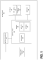
- FIG. 1 is a high-level diagram illustrating an exemplary configuration of a mobile device 102.
- mobile device 102 can be a communications headset such as a Bluetooth ® headset.
- mobile device 102 can be a mobile communication device such as a cellular phone or smartphone.
- mobile device 102 can be a mobile audio and/or video player such as an iPod ®, though it should be understood that mobile device 102 can be practically any device capable of embodying the systems and/or methods described herein.
- Mobile device 102 includes a control circuit 104 which is operatively connected to various hardware and software components that serve to enable compensation for varying degrees of ambient noise at a mobile device 102.
- the control circuit 104 is operatively connected to a processor 106 and a memory 108.
- the memory 108 is accessible by processor 106, thereby enabling processor to receive and execute instructions stored on memory 108.
- the software modules 110 are encoded in memory 108.
- the software modules 110 can comprise a software program or set of instructions executed in processor 106.
- the software modules 110 make up a noise compensation application that is executed by processor 106.
- the processor 106 configures the control circuit 104 to compensate for varying degrees of ambient noise, as will be described in greater detail below.
- FIG. 1 depicts memory 108 on control circuit 104, in an alternate arrangement, memory 108 can be practically any storage medium (such as a hard disk drive, flash memory, etc.) that is operatively connected to the control circuit 106, even if not oriented on control circuit as depicted in FIG. 1 .
- settings 112. can be selected by a user, as will be described in detail below. Each setting has one or more parameters which correspond to various adjustments that can be made within mobile device 102 in order to compensate for various degrees of ambient noise, as will be described in greater detail below.
- One or more of settings 112 can be pre-defined and stored in memory 108, such that the settings 112 can be utilized at the time of the mobile device's 102 initial activation (as well as subsequently). Further, the user can modify, edit, and/or delete the parameters and/or the entirety of these pre-defined settings 112, as will be described in greater detail below. Further, a user can define new settings 112, as will also be described in greater detail below.
- the user can select a default setting from among settings 112 which is to be applied in the absence of the selection of another setting.
- the various settings 112 are preferably associated with a range of speeds of motion, and further include parameters which dictate adjustments to be made to various components of mobile device 102 when certain speeds of motion are detected, as will be described in greater detail below.
- An interface 120 is also operatively connected to control circuit 104.
- the interface 120 preferably includes one or more input device(s) 122 such as a switch, knob, button(s), key(s), touchscreen, etc.
- Interface 120 is operatively connected to the control circuit 104 and serves to receive a selected setting from among the selectable settings 112 stored in memory 108.
- input device 122 of interface 120 can be a knob with three selectable levels corresponding to settings 112 of 'high,' 'medium,' and 'low.' So, when the knob is moved from the 'low' position to the 'medium' position, interface 120 communicates this change to control circuit 104, and the setting corresponding to the 'medium' setting is applied, as will be described in greater detail below.
- Interface 120 also enables a user to define a user setting to be stored among the selectable settings 112 in memory 108. As referenced above, while certain of the settings 112 are preferably pre-defined, it is preferable that the user also have the ability to customize existing settings, and/or to define user settings to conform to the user's personal preferences.
- interface 120 further includes a display screen or any other such presentation device 124 which enables the user to view various options and parameters, and select among them using the input device(s) 122 referenced above.
- the interface 120 can be implemented as a touchscreen, thereby combining the roles of the referenced input device 122 and presentation device 124.
- either one or both of the input device 122 and presentation device 124 can be implemented in a non-visual and/or non-tactile fashion, such as by using a series of audio menus and/or voice commands/prompts to select and/or define settings 112.
- interface 120 further enables the defining of settings 112 by initiating and/or maintaining one or more communication sessions with an external device that is communicatively linked with mobile device 102.
- interface 120 can connect with an external personal computer (PC) through a USB connection, Bluetooth connection, or any other connection/communication medium. The user can then utilize the connected PC to define user settings 112, and/or upload or otherwise communicate new settings which the user has previously defined and/or has obtained from an external source (such as the Internet).
- interface 120 can connect with an external storage device, such as a USB flash drive, and receive one or more settings that are stored thereupon.
- interface 120 can connect to one or more external servers through a network connection.
- interface 120 can utilize a pre-existing network connection, such as an Internet connection, present at mobile device 102. In doing so, the interface can connect with various remote servers which contain settings that are available for users to download. The user can download one or more desired settings and store them in memory 108.
- This functionality of interface 120 which enables the user to obtain and/or update the set of user settings 112 stored in memory 108, is of particular utility when used to obtain and/or update settings pertaining to specific protective helmets and/or motor vehicles, as will be described in greater detail below.
- a detector 114 is also connected to control circuit 104.
- detector 114 is a microphone that receives audible tones from the area immediately surrounding the mobile device 102. The audible tones received by the microphone are transduced into a signal and transmitted to control circuit 104 where they are analyzed for the purpose of compensating for varying degrees of ambient noise, as will be described in greater detail below.
- detector 114 is preferably a microphone
- other devices can also be implemented as a detector 114.
- a global positioning system (GPS) and/or an accelerometer can be implemented as detector 114, either in place of or in addition to the microphone referenced above.
- GPS global positioning system
- the accelerometer can be used to detect the rate of speed that the mobile device 102 (and thus, the user) is traveling and provide information to control circuit 104 for analysis. This detected/provided speed can then be analyzed for the purpose of compensating for varying degrees of ambient noise, as will be described in greater detail below.
- the selectable settings 112 discussed above include various settings that relate to the amount and/or degree of ambient noise that detector 114 is expected to detect.
- the settings 112 include parameters relating to the specific type and/or class of protective helmet that a rider is wearing while using mobile device 102. Being that various protective helmets (such as motorcycle helmets) suppress varying degrees of ambient noise from arriving at the wearer's ears, by selecting and/or inputting a setting corresponding to a type and/or class of helmet, the user can customize the mobile device's 102 ability to better compensate for varying degrees of ambient noise in a manner described in greater detail below.
- settings 112 include parameters relating to a specific motor vehicle model (such as a Harley-Davidson 'Fat Boy') and/or a class of motor vehicles (such as a motor scooter or moped). Being that various models and classes of motor vehicles create varying degrees of ambient noise, by selecting and/or inputting a setting corresponding to a specific model and/or class of motor vehicle being operated, the user can customize the mobile device's 102 ability to compensate for varying degrees of ambient noise in a manner described in greater detail below.
- a specific motor vehicle model such as a Harley-Davidson 'Fat Boy'
- a class of motor vehicles such as a motor scooter or moped
- audio output device 116 is operatively connected to control circuit 104, through an amplification device 118, being a controllable amplification circuit.
- audio output device 116 is a speaker or any other such device capable of transducing signals received from or originated at control circuit 104 (or elsewhere) and projecting audio that is audible to the user.
- speaker 118 is configured as one or more earbuds or earmuffs which are constructed to rest within or directly upon or otherwise near a user's ear.
- audio output device 116 can be a loudspeaker for projecting tones in an enclosed area, for use like a speakerphone.
- the audio output device 116 receives analog communication signals from control circuit 104 by way of amplification device 118 and conveys them as audible tones to the user.
- the referenced tones can originate at the control circuit 104 (such as notification sounds relating to various system notifications), memory 108 (such as stored audio/video media), an external source (such as streaming media accessible by mobile device 102 through a network connection) and/or a communication device (such as from a telephone conversation).
- An amplification device 118 such as an amplifier, is operatively connected to the audio output device 116 and the control circuit 104.
- the amplification device 118 serves to amplify signals received from the control circuit 104 for output by the audio output device 116.
- the operation of the amplification device 118 is controlled by the control circuit, such that the amplification device 118 can amplify various signals at different levels of amplification based on various detected factors, as will be discussed in greater detail below.
- the control circuit 104 can include the amplification device circuitry.
- settings 112 are preferably associated with a range of speeds of motion. That is, settings 112 contain various parameters which configure the operation of amplification device 118 in various ways, depending upon the perceived rate of speed of mobile device 102. Thus, it is usually preferable that at high speeds (which generally result in higher levels of ambient noise), amplification device 118 amplifies signals for output by the audio output device 116 at a higher level, while at lower speeds (where ambient noise is often lower), amplification device 118 amplifies signals for output by the audio output device 116 at a lower level.
- the settings also preferably include parameters corresponding to various prescribed ranges of speeds.
- the amplification device 118 increases the amplification from a 'low' level to a 'medium' level, in a manner described in greater detail below.
- lower and upper limits can be defined in the various ranges such that upper limits can be designated, wherein the amplifier will not further amplify despite further increases in speed, and similarly lower limits can be defined, wherein the amplifier will not amplify below a specified limit, irrespective of how slowly the mobile device is traveling.
- the selectable settings further include parameters which associate various speeds with levels of ambient noise. That is, while the user can define various settings to be associated with various ranges of speed (as described above), the noise compensation application, in conjunction with the settings 112 serves to correlate the user defined speeds and/or ranges of speed with levels of ambient noise. Thus, when detector 114 receives audible tones, these tones can be compared with the levels of ambient noise that are correlated with the defined speeds and/or ranges, as referenced above. In doing so, the noise compensation application can determine the appropriate amplification level for amplification device 118, as will be described in greater detail below.
- settings 112 that correspond to the user's helmet and/or motor vehicle, as referenced above. These settings, which shed further light on the nature of the ambient noise detected by detector 114, thereby allow for greater accuracy in correlating defined ranges of speed with levels of ambient noise, as will be described in greater detail below. It should be noted that in an arrangement where detector 114 is a GPS and/or an accelerometer, the acceleration data generated by the GPS and/or the accelerometer can be utilized in addition to or in place of any detected audio tones.
- the user can utilize interface 120 to define and/or select from among one or more settings 112, as described in detail above.
- Table 1 (below) illustrates a set of two settings - Setting 1 and Setting 2.
- Setting 1 has been designated as the 'Default' setting, as described above. Thus, if the user does not select a setting through interface 120, the parameters of Setting 1 are utilized.
- Both Setting 1 and Setting 2 contain various parameters which can be defined by the user. Among these parameters are 'Vehicle Type/Model,' which corresponds to the specific vehicle the user is operating or riding in. For instance, Setting 1 designates a 'Harley-Davidson (RTM) Fat Boy motorcycle,' while Setting 2 designates a 'Moped.' Identifying the user's vehicle type is significant, as different types of vehicles will produce greater or lesser degrees of ambient noise at different speeds. Similarly, the 'Protective Helmet Type/Class' parameter is significant, because different types of helmets suppress varying amounts of ambient noise at different speeds. For instance, the 'Heavily Padded/Enclosed Helmet' of Setting 1 generally suppresses more ambient noise than the 'Lightly Padded/Open Helmet' of Setting 2.
- the parameters associated with 'Defined Speed Settings / Ranges, Corresponding Amplitudes, and Amplification Adjustments' define ranges of speed for each setting, ranges of amplitudes which correspond to the ranges of speed, and amplification adjustments which are applied in order to compensate for the ambient noise associated with the various amplitude ranges.
- the 'Range of Speed' parameters are preferably defined by the user, and are preferably and primarily intended for the benefit of the user's reference. While the concept of amplitude levels and ranges is not one that many users relate to or fully appreciate, ranges of speed and the increasing noise levels that accompany them are much more accessible and readily understandable by the common user.
- the present system and accompanying method enable the user to define one or more ranges of speed, and further to identify how the amplification device 118 compensates for the increasing ambient noise that accompanies the various speeds.
- the user has defined that within the range of 25-40 MPH, the amplification device 118 should be adjusted to amplify sound to a degree 20% greater than the amplification device's 118 default or normal setting (The 'Amplification Adjustment' parameter is preferably defined by the user, and refers to the degree to which the amplification device 118 should amplify the sound emitted by audio output device 116 beyond the normal/default setting).
- the 'Corresponding Amplitude' parameter is generally not defined by the user. Rather, these parameters are computed and/or received by the noise compensation application, and are correlated with the user defined 'Range of Speed' and 'Amplification Adjustment' parameters, as depicted in Table 1. Based on the totality of user-defined settings (such as 'Vehicle Type/Model,' 'Protective Helmet Type/Class,' and 'Range of Speed'), the noise compensation application computes ranges of amplitudes (designated by the 'Corresponding Amplitude' parameter) that correspond to the user-defined ranges of speed.
- the system cannot detect the actual speed at which mobile device 102 is traveling, the system nevertheless enables the user to define amplification adjustments that correspond to the more familiar and tangible ranges of speed, and then converts these ranges into ranges of amplitudes which are perceptible by mobile device 102 through detector 114, as described above.
- the system itself actually receives an audio input from the detector 114, and compares the input's amplitude with the range of amplitudes in the 'Corresponding Amplitude' parameter.
- the system adjusts the amplification device 118 in accordance with the corresponding 'Amplification Adjustment' parameter, as described in detail above. So, for example, upon selecting 'Setting 2,' when detector 114 receives an input with an amplitude of 50 dB, the amplification device 118 is adjusted to increase its amplification 40% above its default/normal operation.
- any speed below 25 MPH which corresponds to any amplitude level below 35 dB, results in an amplification increase of 10% above the normal/default amplification setting.
- the detector 114 receives no perceptible input (0 dB)
- the amplification device 118 will still be increased to 10% above the normal/default amplification setting.
- any speed above 40 MPH which corresponds to any amplitude level above 60 dB, results in an amplification increase of 50% above the normal/default amplification.
- the upper limit parameter ensures the safety of both the audio output device 116 and the user's ears by not increasing the amplification level to an unsafe degree.
- the 'Corresponding Amplitude' parameter is not input by the user (rather, it is generated by the noise compensation application, as described above), in other arrangements the user may input and/or edit the 'Corresponding Amplitude' parameter as well, thereby providing the user with an additional degree of control and customization.
- routine 200 that illustrates a broad aspect of a method for compensating for varying degrees of ambient noise at a mobile device in accordance with at least one embodiment disclosed herein.
- routine 200 that illustrates a broad aspect of a method for compensating for varying degrees of ambient noise at a mobile device in accordance with at least one embodiment disclosed herein.
- several of the logical operations described herein are implemented (1) as a sequence of computer implemented acts or program modules running on mobile device 102 and/or (2) as interconnected machine logic circuits or circuit modules within the mobile device 102.
- the implementation is a matter of choice dependent on the requirements of the device (e.g., size, energy, consumption, performance, etc.). Accordingly, the logical operations described herein are referred to variously as operations, structural devices, acts, or modules.
- step 202 the user selects one or more settings 112 using interface 120, as referenced above.
- the user has the option of bypassing this step, and in such a scenario the default setting(s), and/or the most recently selected setting are applied.
- step 204 one or more inputs are received by detector 114.
- detector 114 is preferably a microphone, and the various detected inputs are thus audio tones.
- the processor 106 executes one or more of the software modules 110 in conjunction with the settings 112 in order to configure the control circuit to detect one or more amplitudes of the input received from the detector 114. Then, at step 208, these detected amplitude(s) are compared with one or more selected settings 112, specifically settings which correlate between levels of ambient noise and defined speeds and/or ranges of speed, as referenced above. In doing so, the noise compensation application is able to identify the appropriate user-selected speed setting to apply based on the detected amplitude of the audio input.
- step 210 when the detected amplitude is within one of the prescribed ranges (as defined in settings 112), the processor 106 executes one or more of the software modules 110 in conjunction with the settings 112 in order to configure the control circuit to selectively adjust amplification device 118. In doing so, the control circuit 104 serves to compensate for perceived levels of ambient noise by adjusting the operation of amplification device 118. The process then continues by returning to step 204, where further inputs are received by detector 114.
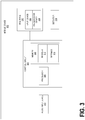
- FIG. 3 a high-level diagram of a mobile device 302 in accordance with another exemplary embodiment is provided.
- the embodiment of FIG.s 3-4 addresses microphone gain issues, and this embodiment can be used in conjunction with the arrangement and method of FIG.s 1-2 , if desired.
- mobile device 302 can be a communications headset such as a Bluetooth ® headset.
- mobile device 302 can be a mobile communication device such as a cellular phone or smartphone, though it should be understood that mobile device 102 can be practically any device capable of embodying the systems and/or methods described herein.
- Mobile device 302 includes a control circuit 304 which is operatively connected to various hardware and software components that serve to enable compensation for varying degrees of ambient noise at a mobile device 302.
- the control circuit 304 is operatively connected to a processor 306 and a memory 308.
- the memory 308 is accessible by processor 306, thereby enabling processor to receive and execute instructions stored on memory 308.
- One or more software modules 310 are encoded in memory 308.
- the software modules 310 can comprise a software program or set of instructions executed in processor 306.
- the software modules 310 make up a noise compensation application that is executed by processor 306.
- the processor 306 configures the control circuit 304 to compensate for varying degrees of ambient noise, as will be described in greater detail below.
- FIG. 3 depicts memory 308 on control circuit 304, in an alternate arrangement, memory 308 can be practically any storage medium (such as a hard disk drive, flash memory, etc.) that is operatively connected to the control circuit 306, even if not oriented on control circuit as depicted in FIG. 3 .
- settings 312 can be selected by a user, as will be described in detail below. Each setting has one or more parameters which correspond to various adjustments that can be made within mobile device 302 in order to compensate for various degrees of ambient noise, as will be described in greater detail below.
- One or more of settings 312 can be pre-defined and stored in memory 308, such that the settings 312 can be utilized at the time of the mobile device's 302 initial activation (as well as subsequently).
- the user can modify, edit, and/or delete the parameters and/or the entirety of these pre-defined settings 312, as will be described in greater detail below.
- a user can define new settings 312, as will also be described in greater detail below.
- the user can select a default setting from among settings 312 which is to be applied in the absence of the selection of another setting.
- the various settings 312 are preferably associated with one or more range(s) of audio frequencies, and further include parameters which dictate adjustments to be made to various components of mobile device 302 when certain frequencies are detected, as will be described in greater detail below.
- An interface 320 is also operatively connected to control circuit 304.
- the interface 120 preferably includes one or more input device(s) 322 such as a switch, knob, button(s), key(s), touchscreen, etc.
- Interface 320 is operatively connected to the control circuit 304 and serves to receive a selected setting from among the selectable settings 312 stored in memory 308.
- input device 322 of interface 120 can be a knob with three selectable levels corresponding to settings 312 of 'high,' 'medium,' and 'low.' So, when the knob is moved from the 'low' position to the 'medium' position, interface 320 communicates this change to control circuit 104, and the setting corresponding to the 'medium' setting is applied, as will be described in greater detail below.
- Interface 320 also enables a user to define a user setting to be stored among the selectable settings 312 in memory 308. As referenced above, while certain of the settings 312 are preferably pre-defined, it is preferable that the user also have the ability to customize existing settings, and/or to define user settings to conform to the user's personal preferences.
- interface 320 further includes a display screen or any other such presentation device 324 which enables the user to view various options and parameters, and select among them using the input device(s) 322 referenced above.
- the interface 320 can be implemented as a touchscreen, thereby combining the roles of the referenced input device 322 and presentation device 324.
- either one or both of the input device 322 and presentation device 324 can be implemented in a non-visual and/or non-tactile fashion, such as by using a series of audio menus and/or voice commands/prompts to select and/or define settings 312.
- interface 320 further enables the defining of settings 312 by initiating and/or maintaining one or more communication sessions with an external device that is communicatively linked with mobile device 302.
- interface 320 can connect with an external personal computer (PC) through a USB connection, Bluetooth connection, or any other connection/communication medium. The user can then utilize the connected PC to define user settings 312, and/or upload or otherwise communicate new settings which the user has previously defined and/or has obtained from an external source (such as the Internet).
- interface 320 can connect with an external storage device, such as a USB flash drive, and receive one or more settings that are stored thereupon.
- interface 320 can connect to one or more external servers through a network connection.
- interface 320 can utilize a pre-existing network connection, such as an Internet connection, present at mobile device 302.
- a pre-existing network connection such as an Internet connection
- the interface can connect with various remote servers which contain settings that are available for users to download.
- the user can download one or more desired settings and store them in memory 308.
- audio input device 316 is a microphone that receives audible tones from the area immediately surrounding the mobile device 302. The audible tones received by the microphone are transduced into a signal and transmitted to control circuit 304 where they are analyzed for the purpose of compensating for varying degrees of ambient noise, as will be described in greater detail below.
- a detector 314 is also connected to control circuit 304.
- detector 314 is a microphone that receives audible tones from the area immediately surrounding the mobile device 302.
- audio input device 316 and detector 314 can be the same microphone, while in other arrangements they can be employed as separate microphones.
- the audible tones received by the microphone of detector 314 are transduced into a signal and transmitted to control circuit 104 where they are analyzed for the purpose of compensating for varying degrees of ambient noise, as will be described in greater detail below.
- settings 312 include various settings that relate to the amount and/or degree of ambient noise that detector 314 and/or audio input device 316 are expected to detect.
- settings 312 can include parameters relating to a range of audio frequencies that correspond to ambient noise, such as engine sounds, vehicle honking, etc.
- the user can select a setting corresponding to a range of audio frequencies, thereby customizing the mobile device's 302 ability to compensate for varying degrees of ambient noise in a manner described in greater detail below.
- the selectable settings include parameters which correspond to a range of audio frequencies associated with ambient noise.
- a 'high' setting can be set to only detect high level frequencies, while a 'low' setting will detect lower level frequencies as well.
- the noise compensation application in conjunction with the settings 312 serves to compare the frequencies detected by the detector 314 with the range of frequencies of the selected setting 312. Based on the parameters of the selected setting 312, the noise compensation application can filter out varying levels of ambient noise received by audio input device 316. In doing so, the noise compensation application improves the quality of the audio signals received by audio input device 316 by filtering elements identified as ambient noise in accordance with the selected setting 312, as will be described in greater detail below.
- routine 400 that illustrates a broad aspect of a method for compensating for varying degrees of ambient noise at a mobile device in accordance with at least one embodiment disclosed herein.
- logical operations described herein are implemented (1) as a sequence of computer implemented acts or program modules running on mobile device 302 and/or (2) as interconnected machine logic circuits or circuit modules within the mobile device 302.
- the implementation is a matter of choice dependent on the requirements of the device (e.g., size, energy, consumption, performance, etc.). Accordingly, the logical operations described herein are referred to variously as operations, structural devices, acts, or modules.
- step 402 the user selects one or more settings 312 using interface 320, as referenced above. Alternatively, the user has the option of bypassing this step, and in such a scenario the default setting(s), and/or the most recently selected setting are applied.
- step 404 one or more inputs are received by detector 314 and audio input device 316. As noted above, both detector 314 and audio input device 316 are preferably microphone(s), and the various detected inputs are thus audio tones.
- the processor 306 executes one or more of the software modules 310 in conjunction with the settings 312 in order to configure the control circuit to detect one or more frequencies of the one or more input(s) received from detector 314 and/or audio input device 316. Then, at step 408, these detected frequencies are compared with one or more selected settings 312, as referenced above. In doing so, the noise compensation application is able to identify the frequency levels that are to be filtered out as ambient noise based on the parameters of the selected setting 312.
- step 410 when the detected frequency is within one of the prescribed ranges (as defined in settings 312), the processor 306 executes one or more of the software modules 310 in conjunction with the settings 312 in order to configure the control circuit 304 to selectively filter the ambient noise associated with the detected frequencies. The process then continues by returning to step 404, where further inputs are received by detector 314.
Landscapes
- Telephone Function (AREA)
- Circuit For Audible Band Transducer (AREA)
Description
- This disclosure relates generally to the field of audio enhancement, and, in particular, to systems and methods for adjusting input and output settings in response to various events and circumstances.
- With the proliferation of mobile communication technologies, in particular cellular phones, individuals have become accustomed to communicating with one another in situations and settings where communication was previously impossible. For instance, it is now common for individuals to conduct telephone conversations while traveling, and even while personally operating motor vehicles such as cars and motorcycles. In many cases, individuals who conduct telephone conversations while in transit utilize personal headsets that can be paired to one or more cellular devices through protocols such as the Bluetooth ® wireless technology standard.
- Most, if not all, cellular devices and/or Bluetooth ® headsets are configured primarily for typical, stationary use. As a result, when these devices are utilized while in motion (often at significant rates of speed), considerable ambient noise is present which interferes with the typical operation of the phone and/or the headset's speaker(s) and/or microphone. For instance, when a driver increases his/her rate of speed, an increasing amount of ambient noise (such as from the revving of a motor vehicle's engine or the increased wind drag) generally makes it more difficult for the user to hear the sounds being emitted from the device's speaker. Furthermore, even if the user manually increases the device's volume setting to account for the increased ambient noise, when the user's rate of speed begins to decrease, the user will likely need to further modify the device's volume settings, or else maintain a volume level that may be uncomfortable.
- This predicament is particularly pronounced for riders or drivers who wear helmets while operating various motor vehicles such as motorcycles, scooters, and all-terrain vehicles. Due to the driver's close proximity to the engine of the vehicle he/she rides, in addition to the wind drag occurring in close proximity to the driver's ear(s), helmet-wearers generally experience high-levels of ambient noise when communicating in transit.
- Various attempts to address the problem of ambient noise in communication devices have been proffered. Generally, these approaches utilize a microphone to detect ambient noise, and the volume levels of the device are adjusted in response to the level of ambient noise detected by the microphone. However, these approaches contain several shortcomings. Firstly, the user is generally not given the option to adjust or customize the way in which the device will adjust for ambient noise (such as a minimum volume level below which the volume should never be adjusted, or a maximum volume level above which the volume should never be adjusted, irrespective of the detected ambient noise). Furthermore, presently available devices do not consider various circumstantial information (for instance, the class or particular model of motor vehicle that the user is driving, or the class or type of helmet that the user is wearing) which is relevant to the device's ability to account for ambient noise.
- In a similar vein, the various circumstances and factors associated with mobile communication while in motion, as described in detail above, interfere with the optimal operation of the microphones of mobile communication devices and headsets. Ambient noise originating from various sources is detected by the microphone, and interferes with the clear reception and/or transmission of the user's voice.
- While various attempts have been made to address this problem - many of them conceptually similar to those referenced above with regard to volume levels - these approaches have not enabled users to adjust and/or customize the way in which the ambient noise is compensated for, and further have not considered the various pertinent circumstantial information referenced above.
- It is with respect to these and other considerations that the disclosure made herein is presented.
-
US 5,907,622 discloses an automatic noise compensation system for audio reproduction equipment.US4558460 discloses an audio apparatus for a vehicle.EP1580883 discloses a set volume control device for on-vehicle audio system. - Technologies are presented herein for a system and method for compensating for varying degrees of ambient noise. According to one aspect, there is provided a system according to claim 1.
- According to another aspect, there is provided a system according to claim 2.
- According to yet another aspect, there is provided a method according to claim 14.
- According to yet another aspect, there is provided a method according to claim 15.
- Further aspects of the invention are defined in the appended claims.
- These and other aspects, features, and advantages can be appreciated from the accompanying description of certain embodiments of the invention and the accompanying drawing figures.
-
-
Fig. 1 is a high-level diagram of a mobile device in accordance with one exemplary embodiment; -
Fig. 2 is a flow diagram illustrating a method for compensating for varying degrees of ambient noise at a mobile device in accordance with one exemplary embodiment; -
Fig. 3 is a high-level diagram of a mobile device in accordance with another exemplary embodiment; and -
Fig. 4 is a flow diagram illustrating a method for compensating for varying degrees of ambient noise at a mobile device in accordance with another exemplary embodiment. - The following detailed description is directed to systems and methods for compensating for varying degrees of ambient noise at a mobile device. References are made to the accompanying drawings that form a part hereof, and which are shown by way of illustration through specific embodiments, arrangements, and examples.
- Referring now to the drawings, it is to be understood that like numerals represent like elements through the several figures, and that not all components and/or steps described and illustrated with reference to the figures are required for all embodiments or arrangements.
FIG. 1 is a high-level diagram illustrating an exemplary configuration of amobile device 102. In one arrangement,mobile device 102 can be a communications headset such as a Bluetooth ® headset. In another arrangement,mobile device 102 can be a mobile communication device such as a cellular phone or smartphone. In yet another arrangement,mobile device 102 can be a mobile audio and/or video player such as an iPod ®, though it should be understood thatmobile device 102 can be practically any device capable of embodying the systems and/or methods described herein. -
Mobile device 102 includes acontrol circuit 104 which is operatively connected to various hardware and software components that serve to enable compensation for varying degrees of ambient noise at amobile device 102. Thecontrol circuit 104 is operatively connected to aprocessor 106 and amemory 108. Thememory 108 is accessible byprocessor 106, thereby enabling processor to receive and execute instructions stored onmemory 108. - One or
more software modules 110 are encoded inmemory 108. Thesoftware modules 110 can comprise a software program or set of instructions executed inprocessor 106. Preferably, thesoftware modules 110 make up a noise compensation application that is executed byprocessor 106. During execution of thesoftware modules 110, theprocessor 106 configures thecontrol circuit 104 to compensate for varying degrees of ambient noise, as will be described in greater detail below. It should be noted that whileFIG. 1 depictsmemory 108 oncontrol circuit 104, in an alternate arrangement,memory 108 can be practically any storage medium (such as a hard disk drive, flash memory, etc.) that is operatively connected to thecontrol circuit 106, even if not oriented on control circuit as depicted inFIG. 1 . - Also stored in
memory 108 are one ormore settings 112. Thesesettings 112 can be selected by a user, as will be described in detail below. Each setting has one or more parameters which correspond to various adjustments that can be made withinmobile device 102 in order to compensate for various degrees of ambient noise, as will be described in greater detail below. One or more ofsettings 112 can be pre-defined and stored inmemory 108, such that thesettings 112 can be utilized at the time of the mobile device's 102 initial activation (as well as subsequently). Further, the user can modify, edit, and/or delete the parameters and/or the entirety of these pre-definedsettings 112, as will be described in greater detail below. Further, a user can definenew settings 112, as will also be described in greater detail below. Additionally, the user can select a default setting from amongsettings 112 which is to be applied in the absence of the selection of another setting. Thevarious settings 112 are preferably associated with a range of speeds of motion, and further include parameters which dictate adjustments to be made to various components ofmobile device 102 when certain speeds of motion are detected, as will be described in greater detail below. - An
interface 120 is also operatively connected tocontrol circuit 104. Theinterface 120 preferably includes one or more input device(s) 122 such as a switch, knob, button(s), key(s), touchscreen, etc.Interface 120 is operatively connected to thecontrol circuit 104 and serves to receive a selected setting from among theselectable settings 112 stored inmemory 108. By way of example,input device 122 ofinterface 120 can be a knob with three selectable levels corresponding tosettings 112 of 'high,' 'medium,' and 'low.' So, when the knob is moved from the 'low' position to the 'medium' position,interface 120 communicates this change to controlcircuit 104, and the setting corresponding to the 'medium' setting is applied, as will be described in greater detail below. -
Interface 120 also enables a user to define a user setting to be stored among theselectable settings 112 inmemory 108. As referenced above, while certain of thesettings 112 are preferably pre-defined, it is preferable that the user also have the ability to customize existing settings, and/or to define user settings to conform to the user's personal preferences. In one arrangement,interface 120 further includes a display screen or any othersuch presentation device 124 which enables the user to view various options and parameters, and select among them using the input device(s) 122 referenced above. In another arrangement, theinterface 120 can be implemented as a touchscreen, thereby combining the roles of the referencedinput device 122 andpresentation device 124. In yet another arrangement, either one or both of theinput device 122 andpresentation device 124 can be implemented in a non-visual and/or non-tactile fashion, such as by using a series of audio menus and/or voice commands/prompts to select and/or definesettings 112. - In one arrangement,
interface 120 further enables the defining ofsettings 112 by initiating and/or maintaining one or more communication sessions with an external device that is communicatively linked withmobile device 102. In one arrangement,interface 120 can connect with an external personal computer (PC) through a USB connection, Bluetooth connection, or any other connection/communication medium. The user can then utilize the connected PC to defineuser settings 112, and/or upload or otherwise communicate new settings which the user has previously defined and/or has obtained from an external source (such as the Internet). In another arrangement,interface 120 can connect with an external storage device, such as a USB flash drive, and receive one or more settings that are stored thereupon. In yet another arrangement,interface 120 can connect to one or more external servers through a network connection. For instance,interface 120 can utilize a pre-existing network connection, such as an Internet connection, present atmobile device 102. In doing so, the interface can connect with various remote servers which contain settings that are available for users to download. The user can download one or more desired settings and store them inmemory 108. This functionality ofinterface 120, which enables the user to obtain and/or update the set ofuser settings 112 stored inmemory 108, is of particular utility when used to obtain and/or update settings pertaining to specific protective helmets and/or motor vehicles, as will be described in greater detail below. - A
detector 114 is also connected to controlcircuit 104. Preferably,detector 114 is a microphone that receives audible tones from the area immediately surrounding themobile device 102. The audible tones received by the microphone are transduced into a signal and transmitted to controlcircuit 104 where they are analyzed for the purpose of compensating for varying degrees of ambient noise, as will be described in greater detail below. - It should be noted that while
detector 114 is preferably a microphone, other devices can also be implemented as adetector 114. By way of example, a global positioning system (GPS) and/or an accelerometer can be implemented asdetector 114, either in place of or in addition to the microphone referenced above. In such an arrangement, the GPS and/or the accelerometer can be used to detect the rate of speed that the mobile device 102 (and thus, the user) is traveling and provide information to controlcircuit 104 for analysis. This detected/provided speed can then be analyzed for the purpose of compensating for varying degrees of ambient noise, as will be described in greater detail below. - At this juncture, it should be noted that the
selectable settings 112 discussed above include various settings that relate to the amount and/or degree of ambient noise thatdetector 114 is expected to detect. Thesettings 112 include parameters relating to the specific type and/or class of protective helmet that a rider is wearing while usingmobile device 102. Being that various protective helmets (such as motorcycle helmets) suppress varying degrees of ambient noise from arriving at the wearer's ears, by selecting and/or inputting a setting corresponding to a type and/or class of helmet, the user can customize the mobile device's 102 ability to better compensate for varying degrees of ambient noise in a manner described in greater detail below. Further,settings 112
include parameters relating to a specific motor vehicle model (such as a Harley-Davidson 'Fat Boy') and/or a class of motor vehicles (such as a motor scooter or moped). Being that various models and classes of motor vehicles create varying degrees of ambient noise, by selecting and/or inputting a setting corresponding to a specific model and/or class of motor vehicle being operated, the user can customize the mobile device's 102 ability to compensate for varying degrees of ambient noise in a manner described in greater detail below. - Also operatively connected to control
circuit 104 is anaudio output device 116, through anamplification device 118, being a controllable amplification circuit. Preferably,audio output device 116 is a speaker or any other such device capable of transducing signals received from or originated at control circuit 104 (or elsewhere) and projecting audio that is audible to the user. In one arrangement,speaker 118 is configured as one or more earbuds or earmuffs which are constructed to rest within or directly upon or otherwise near a user's ear. In an alternate arrangement,audio output device 116 can be a loudspeaker for projecting tones in an enclosed area, for use like a speakerphone. Theaudio output device 116 receives analog communication signals fromcontrol circuit 104 by way ofamplification device 118 and conveys them as audible tones to the user. The referenced tones can originate at the control circuit 104 (such as notification sounds relating to various system notifications), memory 108 (such as stored audio/video media), an external source (such as streaming media accessible bymobile device 102 through a network connection) and/or a communication device (such as from a telephone conversation). - An
amplification device 118, such as an amplifier, is operatively connected to theaudio output device 116 and thecontrol circuit 104. Theamplification device 118 serves to amplify signals received from thecontrol circuit 104 for output by theaudio output device 116. The operation of theamplification device 118 is controlled by the control circuit, such that theamplification device 118 can amplify various signals at different levels of amplification based on various detected factors, as will be discussed in greater detail below. Although the controllable amplification is described in connection with aseparate device 118, thecontrol circuit 104 can include the amplification device circuitry. - It can now be appreciated that the
selectable settings 112 referenced above are preferably associated with a range of speeds of motion. That is,settings 112 contain various parameters which configure the operation ofamplification device 118 in various ways, depending upon the perceived rate of speed ofmobile device 102. Thus, it is usually preferable that at high speeds (which generally result in higher levels of ambient noise),amplification device 118 amplifies signals for output by theaudio output device 116 at a higher level, while at lower speeds (where ambient noise is often lower),amplification device 118 amplifies signals for output by theaudio output device 116 at a lower level. The settings also preferably include parameters corresponding to various prescribed ranges of speeds. For example, from 0-30 miles per hour (MPH) apply a 'low' amplification level, from 30-60 MPH apply a 'medium' amplification level, and above 60 MPH apply a 'high' amplification level. Thus, when the user accelerates from 25 MPH to 35 MPH, theamplification device 118 increases the amplification from a 'low' level to a 'medium' level, in a manner described in greater detail below. Additionally, lower and upper limits can be defined in the various ranges such that upper limits can be designated, wherein the amplifier will not further amplify despite further increases in speed, and similarly lower limits can be defined, wherein the amplifier will not amplify below a specified limit, irrespective of how slowly the mobile device is traveling. - In order to compensate for the ambient noise present at a given speed, the selectable settings further include parameters which associate various speeds with levels of ambient noise. That is, while the user can define various settings to be associated with various ranges of speed (as described above), the noise compensation application, in conjunction with the
settings 112 serves to correlate the user defined speeds and/or ranges of speed with levels of ambient noise. Thus, whendetector 114 receives audible tones, these tones can be compared with the levels of ambient noise that are correlated with the defined speeds and/or ranges, as referenced above. In doing so, the noise compensation application can determine the appropriate amplification level foramplification device 118, as will be described in greater detail below. This assessment is further aided by selectedsettings 112 that correspond to the user's helmet and/or motor vehicle, as referenced above. These settings, which shed further light on the nature of the ambient noise detected bydetector 114, thereby allow for greater accuracy in correlating defined ranges of speed with levels of ambient noise, as will be described in greater detail below. It should be noted that in an arrangement wheredetector 114 is a GPS and/or an accelerometer, the acceleration data generated by the GPS and/or the accelerometer can be utilized in addition to or in place of any detected audio tones. - In order to more fully illustrate the various functions and features disclosed herein, the following example is provided in accordance with one exemplary embodiment, though it should be understood that other embodiments, arrangements, and configurations are also possible:
The user can utilizeinterface 120 to define and/or select from among one ormore settings 112, as described in detail above. Table 1 (below) illustrates a set of two settings - Setting 1 and Setting 2.Table 1 - Example of User-Selectable Settings Parameter Setting 1 (Default) Setting 2 Vehicle Type/Model Harley-Davidson 'Fat Boy' Motorcycle Moped Protective Helmet Type/Class Heavily Padded/Enclosed Helmet Lightly Padded/Open Helmet Defined Speed Settings / Ranges, Corresponding Amplitudes, and Amplification Adjustments Range of Speed Corresponding Amplitude Amplification Adjustment Range of Speed Corresponding Amplitude Amplification Adjustment <25 MPH <35 dB + 10% <15 MPH <25 dB - 25-40 MPH 35-50 dB + 20% 15-30 MPH 25-45 dB +20% 40-55 MPH 50-75 dB +35% 30-40 MPH 45-60 dB +40% > 55 MPH >75 dB +50% >40 MPH >60 dB +50% - In this example, Setting 1 has been designated as the 'Default' setting, as described above. Thus, if the user does not select a setting through
interface 120, the parameters of Setting 1 are utilized. - Both Setting 1 and Setting 2 contain various parameters which can be defined by the user. Among these parameters are 'Vehicle Type/Model,' which corresponds to the specific vehicle the user is operating or riding in. For instance, Setting 1 designates a 'Harley-Davidson (RTM) Fat Boy Motorcycle,' while Setting 2 designates a 'Moped.' Identifying the user's vehicle type is significant, as different types of vehicles will produce greater or lesser degrees of ambient noise at different speeds. Similarly, the 'Protective Helmet Type/Class' parameter is significant, because different types of helmets suppress varying amounts of ambient noise at different speeds. For instance, the 'Heavily Padded/Enclosed Helmet' of Setting 1 generally suppresses more ambient noise than the 'Lightly Padded/Open Helmet' of Setting 2.
- The parameters associated with 'Defined Speed Settings / Ranges, Corresponding Amplitudes, and Amplification Adjustments' define ranges of speed for each setting, ranges of amplitudes which correspond to the ranges of speed, and amplification adjustments which are applied in order to compensate for the ambient noise associated with the various amplitude ranges. It should be noted that the 'Range of Speed' parameters are preferably defined by the user, and are preferably and primarily intended for the benefit of the user's reference. While the concept of amplitude levels and ranges is not one that many users relate to or fully appreciate, ranges of speed and the increasing noise levels that accompany them are much more accessible and readily understandable by the common user. Thus, the present system and accompanying method enable the user to define one or more ranges of speed, and further to identify how the
amplification device 118 compensates for the increasing ambient noise that accompanies the various speeds. For example, in Setting 1, the user has defined that within the range of 25-40 MPH, theamplification device 118 should be adjusted to amplify sound to a degree 20% greater than the amplification device's 118 default or normal setting (The 'Amplification Adjustment' parameter is preferably defined by the user, and refers to the degree to which theamplification device 118 should amplify the sound emitted byaudio output device 116 beyond the normal/default setting). - The 'Corresponding Amplitude' parameter is generally not defined by the user. Rather, these parameters are computed and/or received by the noise compensation application, and are correlated with the user defined 'Range of Speed' and 'Amplification Adjustment' parameters, as depicted in Table 1. Based on the totality of user-defined settings (such as 'Vehicle Type/Model,' 'Protective Helmet Type/Class,' and 'Range of Speed'), the noise compensation application computes ranges of amplitudes (designated by the 'Corresponding Amplitude' parameter) that correspond to the user-defined ranges of speed. Although the system, according to the present embodiment, cannot detect the actual speed at which
mobile device 102 is traveling, the system nevertheless enables the user to define amplification adjustments that correspond to the more familiar and tangible ranges of speed, and then converts these ranges into ranges of amplitudes which are perceptible bymobile device 102 throughdetector 114, as described above. Thus, the system itself actually receives an audio input from thedetector 114, and compares the input's amplitude with the range of amplitudes in the 'Corresponding Amplitude' parameter. Upon identifying the appropriate range, the system adjusts theamplification device 118 in accordance with the corresponding 'Amplification Adjustment' parameter, as described in detail above. So, for example, upon selecting 'Setting 2,' whendetector 114 receives an input with an amplitude of 50 dB, theamplification device 118 is adjusted to increase its amplification 40% above its default/normal operation. - As referenced above, upper and lower limit parameters can be defined. Thus, for example, in Setting 1, any speed below 25 MPH, which corresponds to any amplitude level below 35 dB, results in an amplification increase of 10% above the normal/default amplification setting. In such a case, even if the
detector 114 receives no perceptible input (0 dB), theamplification device 118 will still be increased to 10% above the normal/default amplification setting. Similarly, with reference to Setting 2, any speed above 40 MPH, which corresponds to any amplitude level above 60 dB, results in an amplification increase of 50% above the normal/default amplification. Irrespective of how high of an amplitude level above 60 dB thedetector 114 perceives, under Setting 2 theamplification device 118 will never be increased beyond 50% above its normal/default operation. In doing so, the upper limit parameter ensures the safety of both theaudio output device 116 and the user's ears by not increasing the amplification level to an unsafe degree. - It should be noted that while the preceding example has made reference to the fact that the 'Corresponding Amplitude' parameter is not input by the user (rather, it is generated by the noise compensation application, as described above), in other arrangements the user may input and/or edit the 'Corresponding Amplitude' parameter as well, thereby providing the user with an additional degree of control and customization.
- The operation of the
mobile device 102 and the various elements described above will be appreciated with reference to the method for compensating for varying degrees of ambient noise at a mobile device, as described below, in conjunction withFIG. 2 . - Turning now to
FIG. 2 , a flow diagram is described showing a routine 200 that illustrates a broad aspect of a method for compensating for varying degrees of ambient noise at a mobile device in accordance with at least one embodiment disclosed herein. It should be appreciated that several of the logical operations described herein are implemented (1) as a sequence of computer implemented acts or program modules running onmobile device 102 and/or (2) as interconnected machine logic circuits or circuit modules within themobile device 102. The implementation is a matter of choice dependent on the requirements of the device (e.g., size, energy, consumption, performance, etc.). Accordingly, the logical operations described herein are referred to variously as operations, structural devices, acts, or modules. Various of these operations, structural devices, acts and modules can be implemented in software, in firmware, in special purpose digital logic, and any combination thereof. It should also be appreciated that more or fewer operations can be performed than shown in the figures and described herein. These operations can also be performed in a different order than those described herein. - The process begins at
step 202, where the user selects one ormore settings 112 usinginterface 120, as referenced above. Alternatively, the user has the option of bypassing this step, and in such a scenario the default setting(s), and/or the most recently selected setting are applied. Then, atstep 204, one or more inputs are received bydetector 114. As noted above,detector 114 is preferably a microphone, and the various detected inputs are thus audio tones. - At
step 206, theprocessor 106 executes one or more of thesoftware modules 110 in conjunction with thesettings 112 in order to configure the control circuit to detect one or more amplitudes of the input received from thedetector 114. Then, atstep 208, these detected amplitude(s) are compared with one or more selectedsettings 112, specifically settings which correlate between levels of ambient noise and defined speeds and/or ranges of speed, as referenced above. In doing so, the noise compensation application is able to identify the appropriate user-selected speed setting to apply based on the detected amplitude of the audio input. Then, atstep 210, when the detected amplitude is within one of the prescribed ranges (as defined in settings 112), theprocessor 106 executes one or more of thesoftware modules 110 in conjunction with thesettings 112 in order to configure the control circuit to selectively adjustamplification device 118. In doing so, thecontrol circuit 104 serves to compensate for perceived levels of ambient noise by adjusting the operation ofamplification device 118. The process then continues by returning to step 204, where further inputs are received bydetector 114. - Turning now to
FIG. 3 , a high-level diagram of amobile device 302 in accordance with another exemplary embodiment is provided. The embodiment ofFIG.s 3-4 addresses microphone gain issues, and this embodiment can be used in conjunction with the arrangement and method ofFIG.s 1-2 , if desired. In one arrangement,mobile device 302 can be a communications headset such as a Bluetooth ® headset. In another arrangement,mobile device 302 can be a mobile communication device such as a cellular phone or smartphone, though it should be understood thatmobile device 102 can be practically any device capable of embodying the systems and/or methods described herein. -
Mobile device 302 includes acontrol circuit 304 which is operatively connected to various hardware and software components that serve to enable compensation for varying degrees of ambient noise at amobile device 302. Thecontrol circuit 304 is operatively connected to aprocessor 306 and amemory 308. Thememory 308 is accessible byprocessor 306, thereby enabling processor to receive and execute instructions stored onmemory 308. - One or
more software modules 310 are encoded inmemory 308. Thesoftware modules 310 can comprise a software program or set of instructions executed inprocessor 306. Preferably, thesoftware modules 310 make up a noise compensation application that is executed byprocessor 306. During execution of thesoftware modules 310, theprocessor 306 configures thecontrol circuit 304 to compensate for varying degrees of ambient noise, as will be described in greater detail below. It should be noted that whileFIG. 3 depictsmemory 308 oncontrol circuit 304, in an alternate arrangement,memory 308 can be practically any storage medium (such as a hard disk drive, flash memory, etc.) that is operatively connected to thecontrol circuit 306, even if not oriented on control circuit as depicted inFIG. 3 . - Also stored in
memory 308 are one ormore settings 312. Thesesettings 312 can be selected by a user, as will be described in detail below. Each setting has one or more parameters which correspond to various adjustments that can be made withinmobile device 302 in order to compensate for various degrees of ambient noise, as will be described in greater detail below. One or more ofsettings 312 can be pre-defined and stored inmemory 308, such that thesettings 312 can be utilized at the time of the mobile device's 302 initial activation (as well as subsequently). In one arrangement, the user can modify, edit, and/or delete the parameters and/or the entirety of thesepre-defined settings 312, as will be described in greater detail below. In another arrangement, a user can definenew settings 312, as will also be described in greater detail below. Additionally, the user can select a default setting from amongsettings 312 which is to be applied in the absence of the selection of another setting. Thevarious settings 312 are preferably associated with one or more range(s) of audio frequencies, and further include parameters which dictate adjustments to be made to
various components ofmobile device 302 when certain frequencies are detected, as will be described in greater detail below. - An
interface 320 is also operatively connected to controlcircuit 304. Theinterface 120 preferably includes one or more input device(s) 322 such as a switch, knob, button(s), key(s), touchscreen, etc.Interface 320 is operatively connected to thecontrol circuit 304 and serves to receive a selected setting from among theselectable settings 312 stored inmemory 308. By way of example,input device 322 ofinterface 120 can be a knob with three selectable levels corresponding tosettings 312 of 'high,' 'medium,' and 'low.' So, when the knob is moved from the 'low' position to the 'medium' position,interface 320 communicates this change to controlcircuit 104, and the setting corresponding to the 'medium' setting is applied, as will be described in greater detail below. -
Interface 320 also enables a user to define a user setting to be stored among theselectable settings 312 inmemory 308. As referenced above, while certain of thesettings 312 are preferably pre-defined, it is preferable that the user also have the ability to customize existing settings, and/or to define user settings to conform to the user's personal preferences. In one arrangement,interface 320 further includes a display screen or any othersuch presentation device 324 which enables the user to view various options and parameters, and select among them using the input device(s) 322 referenced above. In another arrangement, theinterface 320 can be implemented as a touchscreen, thereby combining the roles of the referencedinput device 322 andpresentation device 324. In yet another arrangement, either one or both of theinput device 322 andpresentation device 324 can be implemented in a non-visual and/or non-tactile fashion, such as by using a series of audio menus and/or voice commands/prompts to select and/or definesettings 312. - In one arrangement,
interface 320 further enables the defining ofsettings 312 by initiating and/or maintaining one or more communication sessions with an external device that is communicatively linked withmobile device 302. In one arrangement,interface 320 can connect with an external personal computer (PC) through a USB connection, Bluetooth connection, or any other connection/communication medium. The user can then utilize the connected PC to defineuser settings 312, and/or upload or otherwise communicate new settings which the user has previously defined and/or has obtained from an external source (such as the Internet). In another arrangement,interface 320 can connect with an external storage device, such as a USB flash drive, and receive one or more settings that are stored thereupon. In yet another arrangement,interface 320 can connect to one or more external servers through a network connection. For instance,interface 320 can utilize a pre-existing network connection, such as an Internet connection, present atmobile device 302. In doing so, the interface can connect with various remote servers which contain settings that are available for users to download. The user can download one or more desired settings and store them inmemory 308. - Also operatively connected to control
circuit 304 is anaudio input device 316. Preferably,audio input device 316 is a microphone that receives audible tones from the area immediately surrounding themobile device 302. The audible tones received by the microphone are transduced into a signal and transmitted to controlcircuit 304 where they are analyzed for the purpose of compensating for varying degrees of ambient noise, as will be described in greater detail below. - A
detector 314 is also connected to controlcircuit 304. Preferably,detector 314 is a microphone that receives audible tones from the area immediately surrounding themobile device 302. In one arrangement,audio input device 316 anddetector 314 can be the same microphone, while in other arrangements they can be employed as separate microphones. The audible tones received by the microphone ofdetector 314 are transduced into a signal and transmitted to controlcircuit 104 where they are analyzed for the purpose of compensating for varying degrees of ambient noise, as will be described in greater detail below. - At this juncture, it should be noted that the
selectable settings 312 discussed above include various settings that relate to the amount and/or degree of ambient noise thatdetector 314 and/oraudio input device 316 are expected to detect. By way of example,settings 312 can include parameters relating to a range of audio frequencies that correspond to ambient noise, such as engine sounds, vehicle honking, etc. In various travel situations (such as driving in an urban area during a period of heavy traffic), the user can select a setting corresponding to a range of audio frequencies, thereby customizing the mobile device's 302 ability to compensate for varying degrees of ambient noise in a manner described in greater detail below. - In order to compensate for the ambient noise present in various situations, the selectable settings include parameters which correspond to a range of audio frequencies associated with ambient noise. Thus, for example, a 'high' setting can be set to only detect high level frequencies, while a 'low' setting will detect lower level frequencies as well. The noise compensation application, in conjunction with the
settings 312 serves to compare the frequencies detected by thedetector 314 with the range of frequencies of the selected setting 312. Based on the parameters of the selected setting 312, the noise compensation application can filter out varying levels of ambient noise received byaudio input device 316. In doing so, the noise compensation application improves the quality of the audio signals received byaudio input device 316 by filtering elements identified as ambient noise in accordance with the selected setting 312, as will be described in greater detail below. - The operation of the
mobile device 302 and the various elements described above will be appreciated with reference to the method for compensating for varying degrees of ambient noise at a mobile device, as described below, in conjunction withFIG. 4 . - Turning now to
FIG. 4 , a flow diagram is described showing a routine 400 that illustrates a broad aspect of a method for compensating for varying degrees of ambient noise at a mobile device in accordance with at least one embodiment disclosed herein. It should be appreciated that several of the logical operations described herein are implemented (1) as a sequence of computer implemented acts or program modules running onmobile device 302 and/or (2) as interconnected machine logic circuits or circuit modules within themobile device 302. The implementation is a matter of choice dependent on the requirements of the device (e.g., size, energy, consumption, performance, etc.). Accordingly, the logical operations described herein are referred to variously as operations, structural devices, acts, or modules. Various of these operations, structural devices, acts and modules can be implemented in software, in firmware, in special purpose digital logic, and any combination thereof. It should also be appreciated that more or fewer operations can be performed than shown in the figures and described herein. These operations can also be performed in a different order than those described herein. - The process begins at
step 402, where the user selects one ormore settings 312 usinginterface 320, as referenced above. Alternatively, the user has the option of bypassing this step, and in such a scenario the default setting(s), and/or the most recently selected setting are applied. Then, atstep 404, one or more inputs are received bydetector 314 andaudio input device 316. As noted above, bothdetector 314 andaudio input device 316 are preferably microphone(s), and the various detected inputs are thus audio tones. - At
step 406, theprocessor 306 executes one or more of thesoftware modules 310 in conjunction with thesettings 312 in order to configure the control circuit to detect one or more frequencies of the one or more input(s) received fromdetector 314 and/oraudio input device 316. Then, atstep 408, these detected frequencies are compared with one or more selectedsettings 312, as referenced above. In doing so, the noise compensation application is able to identify the frequency levels that are to be filtered out as ambient noise based on the parameters of the selected setting 312. Then, atstep 410, when the detected frequency is within one of the prescribed ranges (as defined in settings 312), theprocessor 306 executes one or more of thesoftware modules 310 in conjunction with thesettings 312 in order to configure thecontrol circuit 304 to selectively filter the ambient noise associated with the detected frequencies. The process then continues by returning to step 404, where further inputs are received bydetector 314. - It should be appreciated that several of the logical operations described herein are implemented (1) as a sequence of computer implemented acts or program modules running on
communication device 104 and/or (2) as interconnected machine logic circuits or circuit modules within thecommunication device 104. The implementation is a matter of choice dependent on the performance and other requirements of the device. Accordingly, the logical operations described herein are referred to variously as operations, structural devices, acts, or modules. Various of these operations, structural devices, acts and modules can be implemented in software, in firmware, in special purpose digital logic, and any combination thereof. It should also be appreciated that more or fewer operations can be performed than shown in the figures and described herein. These operations can also be performed in a different order than those described herein. - The subject matter described above is provided by way of illustration only and should not be construed as limiting. Various modifications and changes can be made to the subject matter described herein without following the example embodiments and applications illustrated and described, and without departing from the true scope of the present invention, which is set forth in the following claims.
Claims (15)
- A system for compensating for varying degrees of ambient noise, the system comprising:a processor (106);a control circuit (104) operatively connected to the processor (106);a memory (108) operatively connected to the control circuit (104) and accessible by the processor (106);a detector (114) operatively connected to the control circuit (104);the processor (106) configured to access the memory (108) and, thereafter, configured to provide selectable settings (112) arranged in two or more sets, each of the sets comprising two or more of the selectable settings (112) that refer to at least vehicle type and helmet type, and for each vehicle type and helmet type combination, an amplification adjustment for each of a plurality of amplitude ranges, and further wherein at least one of the selectable settings being further customizable by a user and at least one of the settings is selectable by the user during operation;an audio output device (116) operatively connected to the control circuit (104); andan amplification device (118) operatively connected to the audio output device and the control circuit (104);wherein the control circuit (104) is configured to compensate for the ambient noise and is further configured to:receive, from the detector (204), an input associated with the ambient noise;detect an amplitude of the input (206);match the detected amplitude with one of the plurality of amplitude ranges of a selected one of the settings (208); andadjust the amplification by the amplification device (118) by an amount corresponding to the amplification adjustment of the matched amplitude range.
- A system for compensating for varying degrees of ambient noise, the system comprising:a processor (306);a control circuit (304) operatively connected to the processor (306);a memory (308) operatively connected to the control circuit (304) and accessible by the processor (306);a detector (314) operatively connected to the control circuit (304);the processor (306) configured to access the memory (308) and, thereafter, configured to provide selectable settings (312) arranged in two or more sets, each of the sets comprising two or more of the selectable settings (312) that refer to at least vehicle type and helmet type, and for each vehicle type and helmet type combination, a plurality of ranges of ambient noise frequencies, and further wherein at least one of the selectable settings being further customizable by a user and at least one of the settings is selectable by the user during operation; andan audio input device (316) operatively connected to the control circuit (304);wherein the control circuit (304) compensates for the ambient noise and is further configured to:receive, from the detector (404), an input associated with the ambient noise;detect a frequency of the input (406);match the detected frequency with one of the plurality of frequency ranges of a elected one of the settings (408); andfilter the ambient noise by an amount corresponding to a range (410) associated with the selected one of the settings.
- The system of claim 2, wherein the detector (314) comprises the audio input device (316).
- The system of claim 2, wherein the detector (314) comprises a secondary audio input device.
- The system of any preceding claim, wherein the detector (114; 314) comprises a microphone.
- The system of any preceding claim, further comprising an interface (120; 320) configured to receive the selected one of the settings (112; 312) from among the selectable settings (112; 312).
- The system of any preceding claim, further comprising an interface (120; 320) for defining a user setting to be stored among the selectable settings (112; 312).
- The system of any preceding claim, wherein the selectable settings (112; 312) include settings associated with a class of helmets.
- The system of any preceding claim, wherein the selectable settings (112; 312) include settings associated with a motor vehicle model.
- The system of any preceding claim, wherein the selectable settings (112; 312) include settings associated with a class of motor vehicles.
- The system of any preceding claim, wherein the amplitude ranges have an upper limit.
- The system of any preceding claim, wherein the amplitude ranges have a lower limit.
- A computer implemented method for compensating for varying degrees of ambient noise at a mobile device using a noise compensation application, the mobile device having a processor (106), a control circuit (104), and a memory (108), the processor (108) configured to access the memory (108) and, thereafter, to provide selectable settings (112) arranged in two or more sets, each of the sets comprising two or more of the selectable settings (112) that refer to at least vehicle type and helmet type, and for each vehicle type and helmet type combination, an amplification adjustment for each of a plurality of amplitude ranges, and further wherein at least one of the selectable settings being further customizable by a user and at least one of the settings is selectable by the user during operation, a detector (114), an audio output device (116), and an amplification device (118), and the noise compensation application encoded in the memory (108) and executed in the processor (106), the method comprising:receiving, from the detector (204), an input associated with the ambient noise;detecting an amplitude of the input (206);matching the detected amplitude with one of the plurality of amplitude ranges of a selected one of the settings (208); andadjusting the amplification device (118) by an amount corresponding to the amplification adjustment of the matched amplitude range.
- A computer implemented method for compensating for varying degrees of ambient noise at a mobile device using a noise compensation application, the mobile device having a processor (306), a control circuit (304), and a memory (308), the processor (306) configured to access the memory (308) and, thereafter, to selectable settings (312) arranged in two or more sets, each of the sets comprising two or more of the selectable settings (312) that refer to at least vehicle type and helmet type, and for each vehicle type and helmet type combination, a plurality of ranges of ambient noise frequencies, and further wherein at least one of the selectable settings being further customizable by a user and at least one of the settings is selectable by the user during operation, a detector, and an audio input device (316), and the noise compensation application encoded in the memory (308) and executed in the processor (306), the method comprising:receiving, from the detector (404), an input associated with the ambient noise;detecting a frequency of the input (406);match the detected frequency with one of the plurality of frequency ranges of a selected one of the settings (408); andfiltering the ambient noise by an amount corresponding to a range (410) associated with the selected one of the settings.
- The method of claim 13 or 14, further comprising the step of: receiving an input from the audio input device (316).
Applications Claiming Priority (1)
| Application Number | Priority Date | Filing Date | Title |
|---|---|---|---|
| US13/021,430 US8494172B2 (en) | 2011-02-04 | 2011-02-04 | System and method for adjusting audio input and output settings |
Publications (2)
| Publication Number | Publication Date |
|---|---|
| EP2485394A1 EP2485394A1 (en) | 2012-08-08 |
| EP2485394B1 true EP2485394B1 (en) | 2019-09-18 |
Family
ID=45566950
Family Applications (1)
| Application Number | Title | Priority Date | Filing Date |
|---|---|---|---|
| EP12275008.6A Active EP2485394B1 (en) | 2011-02-04 | 2012-02-03 | System and method for adjusting audio input and output settings |
Country Status (3)
| Country | Link |
|---|---|
| US (1) | US8494172B2 (en) |
| EP (1) | EP2485394B1 (en) |
| JP (1) | JP5908289B2 (en) |
Families Citing this family (11)
| Publication number | Priority date | Publication date | Assignee | Title |
|---|---|---|---|---|
| TW201306606A (en) * | 2011-07-26 | 2013-02-01 | Hon Hai Prec Ind Co Ltd | Volume adjusting device and method |
| US9020153B2 (en) | 2012-10-24 | 2015-04-28 | Google Inc. | Automatic detection of loudspeaker characteristics |
| US9535455B2 (en) * | 2014-04-11 | 2017-01-03 | Harman International Industries, Inc. | Portable media enhancement device |
| US9923534B2 (en) * | 2014-07-31 | 2018-03-20 | E.F. Johnson Company | Automatic volume control for land mobile radio |
| US9818270B1 (en) * | 2015-04-22 | 2017-11-14 | Tractouch Mobile Partners Llc. | System, method, and apparatus for monitoring audio and vibrational exposure of users and alerting users to excessive exposure |
| US20160336023A1 (en) * | 2015-05-13 | 2016-11-17 | Nuance Communications, Inc. | Methods and apparatus for improving understandability of audio corresponding to dictation |
| US11212385B2 (en) | 2015-07-14 | 2021-12-28 | Kirk Lepchenske | Media control devices, systems and methods |
| DE102017213241A1 (en) * | 2017-08-01 | 2019-02-07 | Bayerische Motoren Werke Aktiengesellschaft | Method, device, mobile user device, computer program for controlling an audio system of a vehicle |
| CN109243481A (en) * | 2018-09-28 | 2019-01-18 | 出门问问信息科技有限公司 | A kind of method of speech processing and device |
| US11876497B2 (en) * | 2019-09-06 | 2024-01-16 | Google Llc | Automatic progressive transition of volume adaptation to environmental noise |
| TWM615116U (en) * | 2021-03-19 | 2021-08-01 | 合世生醫科技股份有限公司 | Audio playing apparatus |
Family Cites Families (7)
| Publication number | Priority date | Publication date | Assignee | Title |
|---|---|---|---|---|
| JPS59230313A (en) * | 1983-06-14 | 1984-12-24 | Honda Motor Co Ltd | Audio system for car |
| JP2569868Y2 (en) | 1990-10-05 | 1998-04-28 | アルパイン 株式会社 | Automotive audio equipment |
| US5907622A (en) * | 1995-09-21 | 1999-05-25 | Dougherty; A. Michael | Automatic noise compensation system for audio reproduction equipment |
| US7099821B2 (en) * | 2003-09-12 | 2006-08-29 | Softmax, Inc. | Separation of target acoustic signals in a multi-transducer arrangement |
| JP4116980B2 (en) | 2004-03-23 | 2008-07-09 | 株式会社ホンダアクセス | Setting volume adjusting device and adjusting method in vehicle audio device |
| WO2007058281A1 (en) * | 2005-11-17 | 2007-05-24 | Young Co., Ltd. | Transmitter/receiver |
| US20100239110A1 (en) | 2009-03-17 | 2010-09-23 | Temic Automotive Of North America, Inc. | Systems and Methods for Optimizing an Audio Communication System |
-
2011
- 2011-02-04 US US13/021,430 patent/US8494172B2/en active Active
-
2012
- 2012-01-25 JP JP2012012795A patent/JP5908289B2/en active Active
- 2012-02-03 EP EP12275008.6A patent/EP2485394B1/en active Active
Non-Patent Citations (1)
| Title |
|---|
| None * |
Also Published As
| Publication number | Publication date |
|---|---|
| JP2012165377A (en) | 2012-08-30 |
| EP2485394A1 (en) | 2012-08-08 |
| JP5908289B2 (en) | 2016-04-26 |
| US8494172B2 (en) | 2013-07-23 |
| US20120201393A1 (en) | 2012-08-09 |
Similar Documents
| Publication | Publication Date | Title |
|---|---|---|
| EP2485394B1 (en) | System and method for adjusting audio input and output settings | |
| JP6600634B2 (en) | System and method for user-controllable auditory environment customization | |
| US10284955B2 (en) | Headphone audio enhancement system | |
| US20080165988A1 (en) | Audio blending | |
| JP6209684B2 (en) | Voice tuning according to the situation | |
| CN114521333A (en) | Active noise reduction audio device and system | |
| US20150365771A1 (en) | Vehicle communiation with a hearing aid device | |
| CN106463107A (en) | Collaboratively processing audio between headset and source | |
| US20180160211A1 (en) | Sports headphone with situational awareness | |
| WO2019001404A1 (en) | User customizable headphone system | |
| EP3155826B1 (en) | Self-voice feedback in communications headsets | |
| US9589558B2 (en) | Motor vehicle noise management | |
| US20160119709A1 (en) | Sound reproduction system with a tactile interface for equalization selection and setting | |
| CN111770404A (en) | Recording method, recording device, electronic equipment and readable storage medium | |
| CA2984083C (en) | Digital signal router for vehicle replacement sound system | |
| JP7558689B2 (en) | Autonomous audio system for a seat headrest, seat headrest, and associated vehicle | |
| WO2015030642A1 (en) | Volume reduction for an electronic device | |
| CN113949981B (en) | Method performed at an electronic device related to a hearing device | |
| WO2008070093A1 (en) | Rear seat audio video systems and methods | |
| US20170034614A1 (en) | Apparatuses and methods for improving operation of earphones | |
| US9161121B2 (en) | Device, headphones and audio player with environmental sound mixing function | |
| US20240364289A1 (en) | Method and system for audio compression for contextual volume control | |
| US12137327B2 (en) | Monitoring of audio signals | |
| US20230011986A1 (en) | Monitoring of Audio Signals | |
| US20230099275A1 (en) | Method and system for context-dependent automatic volume compensation |
Legal Events
| Date | Code | Title | Description |
|---|---|---|---|
| PUAI | Public reference made under article 153(3) epc to a published international application that has entered the european phase |
Free format text: ORIGINAL CODE: 0009012 |
|
| AK | Designated contracting states |
Kind code of ref document: A1 Designated state(s): AL AT BE BG CH CY CZ DE DK EE ES FI FR GB GR HR HU IE IS IT LI LT LU LV MC MK MT NL NO PL PT RO RS SE SI SK SM TR |
|
| AX | Request for extension of the european patent |
Extension state: BA ME |
|
| 17P | Request for examination filed |
Effective date: 20130207 |
|
| 17Q | First examination report despatched |
Effective date: 20130320 |
|
| STAA | Information on the status of an ep patent application or granted ep patent |
Free format text: STATUS: EXAMINATION IS IN PROGRESS |
|
| GRAP | Despatch of communication of intention to grant a patent |
Free format text: ORIGINAL CODE: EPIDOSNIGR1 |
|
| STAA | Information on the status of an ep patent application or granted ep patent |
Free format text: STATUS: GRANT OF PATENT IS INTENDED |
|
| INTG | Intention to grant announced |
Effective date: 20190410 |
|
| GRAS | Grant fee paid |
Free format text: ORIGINAL CODE: EPIDOSNIGR3 |
|
| GRAA | (expected) grant |
Free format text: ORIGINAL CODE: 0009210 |
|
| STAA | Information on the status of an ep patent application or granted ep patent |
Free format text: STATUS: THE PATENT HAS BEEN GRANTED |
|
| AK | Designated contracting states |
Kind code of ref document: B1 Designated state(s): AL AT BE BG CH CY CZ DE DK EE ES FI FR GB GR HR HU IE IS IT LI LT LU LV MC MK MT NL NO PL PT RO RS SE SI SK SM TR |
|
| REG | Reference to a national code |
Ref country code: GB Ref legal event code: FG4D |
|
| REG | Reference to a national code |
Ref country code: CH Ref legal event code: EP |
|
| REG | Reference to a national code |
Ref country code: DE Ref legal event code: R096 Ref document number: 602012064071 Country of ref document: DE |
|
| REG | Reference to a national code |
Ref country code: AT Ref legal event code: REF Ref document number: 1182515 Country of ref document: AT Kind code of ref document: T Effective date: 20191015 |
|
| REG | Reference to a national code |
Ref country code: IE Ref legal event code: FG4D |
|
| REG | Reference to a national code |
Ref country code: NL Ref legal event code: FP |
|
| PG25 | Lapsed in a contracting state [announced via postgrant information from national office to epo] |
Ref country code: HR Free format text: LAPSE BECAUSE OF FAILURE TO SUBMIT A TRANSLATION OF THE DESCRIPTION OR TO PAY THE FEE WITHIN THE PRESCRIBED TIME-LIMIT Effective date: 20190918 Ref country code: BG Free format text: LAPSE BECAUSE OF FAILURE TO SUBMIT A TRANSLATION OF THE DESCRIPTION OR TO PAY THE FEE WITHIN THE PRESCRIBED TIME-LIMIT Effective date: 20191218 Ref country code: LT Free format text: LAPSE BECAUSE OF FAILURE TO SUBMIT A TRANSLATION OF THE DESCRIPTION OR TO PAY THE FEE WITHIN THE PRESCRIBED TIME-LIMIT Effective date: 20190918 Ref country code: NO Free format text: LAPSE BECAUSE OF FAILURE TO SUBMIT A TRANSLATION OF THE DESCRIPTION OR TO PAY THE FEE WITHIN THE PRESCRIBED TIME-LIMIT Effective date: 20191218 Ref country code: SE Free format text: LAPSE BECAUSE OF FAILURE TO SUBMIT A TRANSLATION OF THE DESCRIPTION OR TO PAY THE FEE WITHIN THE PRESCRIBED TIME-LIMIT Effective date: 20190918 Ref country code: FI Free format text: LAPSE BECAUSE OF FAILURE TO SUBMIT A TRANSLATION OF THE DESCRIPTION OR TO PAY THE FEE WITHIN THE PRESCRIBED TIME-LIMIT Effective date: 20190918 |
|
| REG | Reference to a national code |
Ref country code: LT Ref legal event code: MG4D |
|
| PG25 | Lapsed in a contracting state [announced via postgrant information from national office to epo] |
Ref country code: RS Free format text: LAPSE BECAUSE OF FAILURE TO SUBMIT A TRANSLATION OF THE DESCRIPTION OR TO PAY THE FEE WITHIN THE PRESCRIBED TIME-LIMIT Effective date: 20190918 Ref country code: GR Free format text: LAPSE BECAUSE OF FAILURE TO SUBMIT A TRANSLATION OF THE DESCRIPTION OR TO PAY THE FEE WITHIN THE PRESCRIBED TIME-LIMIT Effective date: 20191219 Ref country code: AL Free format text: LAPSE BECAUSE OF FAILURE TO SUBMIT A TRANSLATION OF THE DESCRIPTION OR TO PAY THE FEE WITHIN THE PRESCRIBED TIME-LIMIT Effective date: 20190918 Ref country code: LV Free format text: LAPSE BECAUSE OF FAILURE TO SUBMIT A TRANSLATION OF THE DESCRIPTION OR TO PAY THE FEE WITHIN THE PRESCRIBED TIME-LIMIT Effective date: 20190918 |
|
| REG | Reference to a national code |
Ref country code: AT Ref legal event code: MK05 Ref document number: 1182515 Country of ref document: AT Kind code of ref document: T Effective date: 20190918 |
|
| PG25 | Lapsed in a contracting state [announced via postgrant information from national office to epo] |
Ref country code: PT Free format text: LAPSE BECAUSE OF FAILURE TO SUBMIT A TRANSLATION OF THE DESCRIPTION OR TO PAY THE FEE WITHIN THE PRESCRIBED TIME-LIMIT Effective date: 20200120 Ref country code: EE Free format text: LAPSE BECAUSE OF FAILURE TO SUBMIT A TRANSLATION OF THE DESCRIPTION OR TO PAY THE FEE WITHIN THE PRESCRIBED TIME-LIMIT Effective date: 20190918 Ref country code: AT Free format text: LAPSE BECAUSE OF FAILURE TO SUBMIT A TRANSLATION OF THE DESCRIPTION OR TO PAY THE FEE WITHIN THE PRESCRIBED TIME-LIMIT Effective date: 20190918 Ref country code: RO Free format text: LAPSE BECAUSE OF FAILURE TO SUBMIT A TRANSLATION OF THE DESCRIPTION OR TO PAY THE FEE WITHIN THE PRESCRIBED TIME-LIMIT Effective date: 20190918 Ref country code: ES Free format text: LAPSE BECAUSE OF FAILURE TO SUBMIT A TRANSLATION OF THE DESCRIPTION OR TO PAY THE FEE WITHIN THE PRESCRIBED TIME-LIMIT Effective date: 20190918 Ref country code: PL Free format text: LAPSE BECAUSE OF FAILURE TO SUBMIT A TRANSLATION OF THE DESCRIPTION OR TO PAY THE FEE WITHIN THE PRESCRIBED TIME-LIMIT Effective date: 20190918 |
|
| PG25 | Lapsed in a contracting state [announced via postgrant information from national office to epo] |
Ref country code: SM Free format text: LAPSE BECAUSE OF FAILURE TO SUBMIT A TRANSLATION OF THE DESCRIPTION OR TO PAY THE FEE WITHIN THE PRESCRIBED TIME-LIMIT Effective date: 20190918 Ref country code: SK Free format text: LAPSE BECAUSE OF FAILURE TO SUBMIT A TRANSLATION OF THE DESCRIPTION OR TO PAY THE FEE WITHIN THE PRESCRIBED TIME-LIMIT Effective date: 20190918 Ref country code: IS Free format text: LAPSE BECAUSE OF FAILURE TO SUBMIT A TRANSLATION OF THE DESCRIPTION OR TO PAY THE FEE WITHIN THE PRESCRIBED TIME-LIMIT Effective date: 20200224 Ref country code: CZ Free format text: LAPSE BECAUSE OF FAILURE TO SUBMIT A TRANSLATION OF THE DESCRIPTION OR TO PAY THE FEE WITHIN THE PRESCRIBED TIME-LIMIT Effective date: 20190918 |
|
| REG | Reference to a national code |
Ref country code: DE Ref legal event code: R097 Ref document number: 602012064071 Country of ref document: DE |
|
| PLBE | No opposition filed within time limit |
Free format text: ORIGINAL CODE: 0009261 |
|
| STAA | Information on the status of an ep patent application or granted ep patent |
Free format text: STATUS: NO OPPOSITION FILED WITHIN TIME LIMIT |
|
| PG2D | Information on lapse in contracting state deleted |
Ref country code: IS |
|
| PG25 | Lapsed in a contracting state [announced via postgrant information from national office to epo] |
Ref country code: DK Free format text: LAPSE BECAUSE OF FAILURE TO SUBMIT A TRANSLATION OF THE DESCRIPTION OR TO PAY THE FEE WITHIN THE PRESCRIBED TIME-LIMIT Effective date: 20190918 Ref country code: IS Free format text: LAPSE BECAUSE OF FAILURE TO SUBMIT A TRANSLATION OF THE DESCRIPTION OR TO PAY THE FEE WITHIN THE PRESCRIBED TIME-LIMIT Effective date: 20200119 |
|
| 26N | No opposition filed |
Effective date: 20200619 |
|
| PG25 | Lapsed in a contracting state [announced via postgrant information from national office to epo] |
Ref country code: SI Free format text: LAPSE BECAUSE OF FAILURE TO SUBMIT A TRANSLATION OF THE DESCRIPTION OR TO PAY THE FEE WITHIN THE PRESCRIBED TIME-LIMIT Effective date: 20190918 |
|
| REG | Reference to a national code |
Ref country code: DE Ref legal event code: R082 Ref document number: 602012064071 Country of ref document: DE Representative=s name: WEICKMANN & WEICKMANN PATENT- UND RECHTSANWAEL, DE Ref country code: DE Ref legal event code: R081 Ref document number: 602012064071 Country of ref document: DE Owner name: CARDO SYSTEMS, LTD., IL Free format text: FORMER OWNER: CARDO SYSTEMS INC., PITTSBURGH, PA., US |
|
| REG | Reference to a national code |
Ref country code: CH Ref legal event code: PL |
|
| REG | Reference to a national code |
Ref country code: NL Ref legal event code: MM Effective date: 20200301 |
|
| REG | Reference to a national code |
Ref country code: BE Ref legal event code: MM Effective date: 20200229 |
|
| PG25 | Lapsed in a contracting state [announced via postgrant information from national office to epo] |
Ref country code: LU Free format text: LAPSE BECAUSE OF NON-PAYMENT OF DUE FEES Effective date: 20200203 Ref country code: MC Free format text: LAPSE BECAUSE OF FAILURE TO SUBMIT A TRANSLATION OF THE DESCRIPTION OR TO PAY THE FEE WITHIN THE PRESCRIBED TIME-LIMIT Effective date: 20190918 |
|
| PG25 | Lapsed in a contracting state [announced via postgrant information from national office to epo] |
Ref country code: CH Free format text: LAPSE BECAUSE OF NON-PAYMENT OF DUE FEES Effective date: 20200229 Ref country code: LI Free format text: LAPSE BECAUSE OF NON-PAYMENT OF DUE FEES Effective date: 20200229 |
|
| REG | Reference to a national code |
Ref country code: GB Ref legal event code: 732E Free format text: REGISTERED BETWEEN 20201105 AND 20201111 |
|
| PG25 | Lapsed in a contracting state [announced via postgrant information from national office to epo] |
Ref country code: NL Free format text: LAPSE BECAUSE OF NON-PAYMENT OF DUE FEES Effective date: 20200301 |
|
| PG25 | Lapsed in a contracting state [announced via postgrant information from national office to epo] |
Ref country code: IE Free format text: LAPSE BECAUSE OF NON-PAYMENT OF DUE FEES Effective date: 20200203 |
|
| PG25 | Lapsed in a contracting state [announced via postgrant information from national office to epo] |
Ref country code: BE Free format text: LAPSE BECAUSE OF NON-PAYMENT OF DUE FEES Effective date: 20200229 |
|
| PG25 | Lapsed in a contracting state [announced via postgrant information from national office to epo] |
Ref country code: TR Free format text: LAPSE BECAUSE OF FAILURE TO SUBMIT A TRANSLATION OF THE DESCRIPTION OR TO PAY THE FEE WITHIN THE PRESCRIBED TIME-LIMIT Effective date: 20190918 Ref country code: MT Free format text: LAPSE BECAUSE OF FAILURE TO SUBMIT A TRANSLATION OF THE DESCRIPTION OR TO PAY THE FEE WITHIN THE PRESCRIBED TIME-LIMIT Effective date: 20190918 Ref country code: CY Free format text: LAPSE BECAUSE OF FAILURE TO SUBMIT A TRANSLATION OF THE DESCRIPTION OR TO PAY THE FEE WITHIN THE PRESCRIBED TIME-LIMIT Effective date: 20190918 |
|
| PG25 | Lapsed in a contracting state [announced via postgrant information from national office to epo] |
Ref country code: MK Free format text: LAPSE BECAUSE OF FAILURE TO SUBMIT A TRANSLATION OF THE DESCRIPTION OR TO PAY THE FEE WITHIN THE PRESCRIBED TIME-LIMIT Effective date: 20190918 |
|
| P01 | Opt-out of the competence of the unified patent court (upc) registered |
Effective date: 20230515 |
|
| PGFP | Annual fee paid to national office [announced via postgrant information from national office to epo] |
Ref country code: DE Payment date: 20240131 Year of fee payment: 13 Ref country code: GB Payment date: 20240219 Year of fee payment: 13 |
|
| PGFP | Annual fee paid to national office [announced via postgrant information from national office to epo] |
Ref country code: IT Payment date: 20240228 Year of fee payment: 13 Ref country code: FR Payment date: 20240221 Year of fee payment: 13 |