EP2485196B1 - A vending machine for foods and products in general - Google Patents
A vending machine for foods and products in general Download PDFInfo
- Publication number
- EP2485196B1 EP2485196B1 EP20120152487 EP12152487A EP2485196B1 EP 2485196 B1 EP2485196 B1 EP 2485196B1 EP 20120152487 EP20120152487 EP 20120152487 EP 12152487 A EP12152487 A EP 12152487A EP 2485196 B1 EP2485196 B1 EP 2485196B1
- Authority
- EP
- European Patent Office
- Prior art keywords
- support
- vending machine
- selected product
- collection compartment
- delivery mechanism
- Prior art date
- Legal status (The legal status is an assumption and is not a legal conclusion. Google has not performed a legal analysis and makes no representation as to the accuracy of the status listed.)
- Active
Links
- 235000013305 food Nutrition 0.000 title claims description 9
- 230000007246 mechanism Effects 0.000 claims description 26
- 239000011521 glass Substances 0.000 claims description 9
- 230000004913 activation Effects 0.000 claims description 7
- 235000013361 beverage Nutrition 0.000 claims description 5
- 239000004615 ingredient Substances 0.000 description 6
- 238000002360 preparation method Methods 0.000 description 3
- 235000012171 hot beverage Nutrition 0.000 description 2
- XLYOFNOQVPJJNP-UHFFFAOYSA-N water Substances O XLYOFNOQVPJJNP-UHFFFAOYSA-N 0.000 description 2
- 241001122767 Theaceae Species 0.000 description 1
- 238000000605 extraction Methods 0.000 description 1
- 230000005484 gravity Effects 0.000 description 1
- 238000003780 insertion Methods 0.000 description 1
- 230000037431 insertion Effects 0.000 description 1
- 239000000463 material Substances 0.000 description 1
- 239000000203 mixture Substances 0.000 description 1
- 239000011505 plaster Substances 0.000 description 1
- 230000001105 regulatory effect Effects 0.000 description 1
Images

Classifications
-
- G—PHYSICS
- G07—CHECKING-DEVICES
- G07F—COIN-FREED OR LIKE APPARATUS
- G07F13/00—Coin-freed apparatus for controlling dispensing or fluids, semiliquids or granular material from reservoirs
- G07F13/10—Coin-freed apparatus for controlling dispensing or fluids, semiliquids or granular material from reservoirs with associated dispensing of containers, e.g. cups or other articles
-
- G—PHYSICS
- G07—CHECKING-DEVICES
- G07F—COIN-FREED OR LIKE APPARATUS
- G07F11/00—Coin-freed apparatus for dispensing, or the like, discrete articles
- G07F11/02—Coin-freed apparatus for dispensing, or the like, discrete articles from non-movable magazines
- G07F11/04—Coin-freed apparatus for dispensing, or the like, discrete articles from non-movable magazines in which magazines the articles are stored one vertically above the other
- G07F11/16—Delivery means
- G07F11/24—Rotary or oscillatory members
-
- G—PHYSICS
- G07—CHECKING-DEVICES
- G07F—COIN-FREED OR LIKE APPARATUS
- G07F11/00—Coin-freed apparatus for dispensing, or the like, discrete articles
- G07F11/02—Coin-freed apparatus for dispensing, or the like, discrete articles from non-movable magazines
- G07F11/38—Coin-freed apparatus for dispensing, or the like, discrete articles from non-movable magazines in which the magazines are horizontal
- G07F11/42—Coin-freed apparatus for dispensing, or the like, discrete articles from non-movable magazines in which the magazines are horizontal the articles being delivered by motor-driven means
Definitions
- the present invention relates to a vending machine for foods and products in general, of the type pointed out in the preamble of the first claim.
- the vending machine is used for dispensing foodstuff, drinks or any other food items in response to a command/input supplied by the user.
- vending machines or dispensers substantially consist of a single central body internally having said food items or the ingredients necessary for preparing them, suitably housed in the upper part thereof so as to facilitate movement of said articles, as hereinafter described.
- a dispenser of hot beverages i.e. a dispenser suitable for preparation of the selected product
- a dispenser suitable for preparation of the selected product it contemplates a plurality of containers inside which the powdered ingredients are stored, a vessel containing water to be used for preparing the beverages and a preparation system adapted to select and mix the ingredients with water so as to make the selected product.
- a plurality of interface elements are present on the outer surface of the central body, which elements enable a user to set the dispenser or vending machine in operation.
- these elements preferably placed in the dispenser's upper part so as to facilitate use thereof, can comprise a push-button panel through which the product is selected and a payment apparatus by which, through insertion of coins for example, the amount corresponding to the selected product will be paid.
- known vending machines in the lower part thereof and, more specifically, under the interface elements and the products/ingredients, have a collection compartment inside which the product is collected and a picking up opening adapted to enable access to said compartment and through which the user removes the product by introducing his/her hand into said compartment.
- access to said compartment is usually regulated through a vertically slidable plate so that, when the user picks up the product, he/she lifts said plate by one hand while he/she removes the product with the other hand, then moving his/her hands away from the compartment thus enabling the plate, pushed by the force of gravity, to close access to the inner compartment.
- the technical task underlying the present invention is to conceive a vending machine for foods and products in general capable of substantially obviating the mentioned drawbacks.
- Another important aim of the invention is to conceive a vending machine enabling comfortable and practical picking up of the product.
- vending machine or dispenser for foods and products in general according to the invention is generally denoted at 1.
- the vending machine 1 is adapted to be used for dispensing beverages, foods, magazines or any other product suitably disposed and/or prepared inside the dispenser itself.
- the vending machine 1 is adapted to dispense a selected product 20 to a user 1a, based on a command/input supplied by said user.
- the vending machine 1 in known manner comprises a holding structure containing a plurality of products and defining a collection compartment 3 adapted to receive the selected product 20 and having an inlet section 3a enabling picking up of the selected product 20 by the user 1 a.
- the inlet section 3a has a parallelogram-shaped profile adapted to promote extraction of the selected product 20, as better described in the following.
- a closing/opening mechanism not shown in the figures, comprising a panel, a shutter or a plate adapted to close said section 3a and a motor or other actuating device adapted to move said plate so as to clear or close access to said section 3a.
- vending machine 1 Inside the holding structure the vending machine 1 has, in known manner, storage systems and dispensing mechanisms, not shown in the figures, that vary depending on the type of product delivered by dispenser 1.
- the holding structure would internally have a plurality of said previously packaged products and a dispensing mechanism adapted to move the selected product causing it to reach the collection compartment.
- the holding structure contemplates a series of shelves on which the products are disposed along orderly rows and, for each row of products, a helical element that, through rotation, causes advancing of the products of a row and then falling into compartment 3 of the head product corresponding to the selected product 20.
- the vending machine 1 in addition to dispensing the selected product 20, is also adapted to prepare said product 20. Therefore, the holding structure has, in known manner, a plurality of containers in which the ingredients are housed and a particular distribution/preparation mechanism selecting the necessary ingredients and preparing the selected product 20.
- the vending machine 1 in addition to the aforesaid elements, comprises an innovative delivery mechanism 4 at least partly housed inside the collection compartment 3 and preferably fully housed in said compartment 3.
- the delivery mechanism 4 comprises a support 5 adapted to define a supporting surface 5a on which the selected product 20 rests when it comes to the inside of the collection compartment 3; actuating means 6 adapted to extract the selected product 20 from the collection compartment 3; and a fastening body 7 suitable to enable constraint of the delivery mechanism 4 at compartment 3.
- the actuating means 6 moves the support 5 and consequently the selected product 20 defining, for the delivery mechanism 4, a configuration at rest in which the support 5 is inside said collection compartment 3, and a grip configuration in which the support 5 is at the outside of compartment 3. Therefore, said means 6 moves support 5 and consequently the selected product 20 by a movement having a first component substantially perpendicular to the inlet section 3a so as to vary the distance of support 5 from the inlet section 3a.
- Said first component can therefore be obtained through a translation along a movement plane parallel to said supporting plane of the vending machine 1.
- this first component is preferably obtained through rotation of support 5 relative to a rotation axis substantially perpendicular to the supporting plane of the vending machine 1 and, more preferably, said first rotation is substantially of 90°.
- Movement of support 5, obtained through the actuating means 6 is further characterised by the presence of a second component almost perpendicular to said supporting plane of the vending machine 1 and adapted to enable the height of the selected product 20 to be varied relative to the supporting plane of the dispenser.
- said second component is adapted to determine a translation along said line perpendicular to the supporting plane that is substantially equal to 200 mm.
- the actuating means 6 is adapted to extract the selected product 20 from the collection compartment 3 by shifting support 5 and consequently the selected product 20 by a movement having both the first component and the second component.
- the actuating means 6 is therefore adapted to make support 5 carry out a rotation-translation motion, i.e. move support 5 along a helical trajectory.
- two distinct and simultaneous movements can be identified: a rotation movement defining the first component the width of which is substantially equal to 90° and which is carried out relative to an axis perpendicular to the supporting plane; and a translation movement defining the second component, along a direction almost parallel to said rotation axis.
- the actuating means 6 can therefore be provided with a working screw 6a having a transverse extension direction, preferably perpendicular to the supporting plane of dispenser 1 and adapted to define at least the first component of motion of support 5; and guide locators including a housing 6b rigidly secured to the fastening body 7, which is adapted to guide movement of said support 5.
- Housing 6b preferably has a semicircular section so as to partly surround the working screw 6a; and a motor 6c adapted to move said working screw 6a.
- Housing 6b enables the above described helical motion of support 5 to be defined and is therefore advantageously provided with a slit 6d adapted to come into engagement, as better described hereinafter, with support 5 and having a profile substantially coincident with the above described helical trajectory so as to guide movement of support 5 in its rotational-translational motion, i.e. during passage of the delivery mechanism 4 from the at-rest configuration to the grip configuration ( Fig. 3 ).
- the support 5 has a first portion 5b defining the supporting surface 5a, a second portion 5c adapted to fasten support 5 between the actuating means 6 and body 7, and a third portion 5d adapted to connect said two portions 5b and 5c.
- the first portion 5b when dispenser 1 deals with previously packaged products such as drinks or sandwiches, consists of a suitably shaped plate or other similar element adapted to define an appropriate supporting surface 5a.
- the first portion 5b when dispenser 1 deals with beverages contained in a glass 20a, such as coffee and tea, the first portion 5b has a C-shaped profile, so as to at least partly surround and support glass 20a, as shown in Figs. 1-3 .
- the second portion 5c is at least partly housed between the working screw 6a and housing 6b so as to enable engagement of support 5 both with screw 6a and with slit 6d.
- it consists of a hollow cylindrical body having an inner wall provided with threading so that it engages with the working screw 6a, and an engagement tooth 5e protruding from the outer surface of the cylindrical body and suitable for engagement with slit 6d.
- the third portion 5d preferably has a substantially L-shaped profile in which the following parts can be identified: an initial plate, close to the second portion 5c, substantially parallel to the ground and of such a length that, when the mechanism 4 is in the grip configuration, it enables the first portion to fully come out of the collection compartment 3; and a final plate inclined to the former and adapted to keep the first portion 5a and consequently the selected product 20 in a raised position relative to the ground.
- Dispenser 1 can comprise activation means adapted to operate activation of the delivery mechanism 4, i.e. of the means adapted to operate passage of the delivery mechanism 4 from the at-rest configuration to the grip configuration and vice versa.
- said activation means is also adapted to operate the above described closing/opening mechanism of the inlet section 3a.
- This activation means comprises several sensors and in particular at least one sensor 8 adapted to automatically detect the presence of the selected product 20 on the first portion 5b of support 5.
- sensor 8 is a pressure sensor, i.e. a sensor capable of detecting the presence of the selected product 20 on support 5 due to the weight force, i.e. the force exerted by the product 20 on the sensor itself.
- the vending machine 1 at the outer surface of the holding structure 2 corresponding to the inlet section 3a is provided with interface elements adapted to enable the user 1a to operate the vending machine 1.
- the interface elements comprise a known payment apparatus 9 enabling the user 1a to pay the price corresponding to the selected product; and a push-button panel 10 for selection of the desired product from a plurality of products contained in the holding structure thereby allowing said command/input to be sent to the vending machine 1.
- the push-button panel 10 is such made as to define a pressure plane having a little inclination angle relative to the normal to the supporting plane of the vending machine 1, substantially of 3° for example. It has a series of inscriptions 10a, each identifying one of the products present in dispenser 1 and at least partly made in high relief relative to said pressure plane.
- the vending machine 1 has the delivery mechanism 5 in the at-rest configuration and support 5 is therefore inside the collection compartment 3.
- the user 1 a selects a product 20 through the push-button panel 10, inserts the related amount through the payment apparatus 9 and activates the vending machine 1 that prepares the selected product 20 and places it on support 5 determining actuation of a sensor 8.
- dispenser 1 places the glass 20a on the first portion 5b close to sensors 8 and then fills the glass 20a with the selected beverage.
- filling of glass 20a gives rise to an increase in weight of the glass and therefore to actuation of sensors 8.
- sensors 8 activate the closing/opening mechanism that will open the inlet section 3a and, substantially simultaneously, the delivery mechanism 5 that moves from the at-rest configuration to the grip configuration.
- motor 5c sets the working screw 6a and support 5 in rotation, while housing 6b keeps stationary.
- said movement of support 5 relative to housing 6b causes sliding of the engagement tooth 5e inside slit 6d and therefore the helical motion ( Fig. 3 ) of support 5 and of the selected product 20.
- the selected product 20 substantially carries out a rotation of about 90° so that the selected product 20 is extracted from compartment 3, as well as a translation of at least about 200 mm raising the product itself.
- this double movement is facilitated by the parallelogram shape of the inlet section 3a that will prevent glass 20a and support 5 from bumping against the edge of section 3a.
- support 5 has the third portion 5d at least partly out of said compartment 3 and, more specifically, it has the second plate of the third portion 56d out of the collection compartment 3, as shown in Figs. 1 and 2 .
- the delivery mechanism 4 stops and waits for picking up of the product 20.
- the closing/opening mechanism closes the inlet section 3a bringing dispenser 1 back to the initial state.
- the vending machine 1 when the selected product 20 has to be picked up, enables the latter to be in a particularly comfortable and easy position for this operation.
- dispenser 1 enables a user 1a to pick up the selected product 20 without said user being obliged to bend and/or to kneel down.
- the product 20 at the moment of picking it up is in an ideal position also for partly disabled people and/or people on wheelchairs.
- Another advantage resides in the particular position of the push-button panel 10 that, being slightly inclined relative to the normal to the supporting plane of dispenser 1, offers a comfortable and practical supporting surface for the user's hand at the moment of selection.
- a further advantage belonging to the vending machine 1 is obtained due to the inscriptions 10a that, being at least partly made in high relief, enable even the blind to easily identify the desired product.
- Another important advantage is obtained by virtue of the parallelogram-shaped profile of the inlet section 3a as it prevents the support 5 from bumping against said profile during its movements, which will cause the selected product 20 to fall.
Landscapes
- Physics & Mathematics (AREA)
- General Physics & Mathematics (AREA)
- Control Of Vending Devices And Auxiliary Devices For Vending Devices (AREA)
- Confectionery (AREA)
- Vending Machines For Individual Products (AREA)
Description
- The present invention relates to a vending machine for foods and products in general, of the type pointed out in the preamble of the first claim. Preferably, the vending machine is used for dispensing foodstuff, drinks or any other food items in response to a command/input supplied by the user.
- Similar vending machines are described in patent applications:
EP-A-1588981 ;EP-A-1672598 andEP-A-15646 - It is known that presently used vending machines or dispensers substantially consist of a single central body internally having said food items or the ingredients necessary for preparing them, suitably housed in the upper part thereof so as to facilitate movement of said articles, as hereinafter described.
- In particular, in case of a dispenser of hot beverages, i.e. a dispenser suitable for preparation of the selected product, it contemplates a plurality of containers inside which the powdered ingredients are stored, a vessel containing water to be used for preparing the beverages and a preparation system adapted to select and mix the ingredients with water so as to make the selected product.
- A plurality of interface elements are present on the outer surface of the central body, which elements enable a user to set the dispenser or vending machine in operation. In detail, these elements, preferably placed in the dispenser's upper part so as to facilitate use thereof, can comprise a push-button panel through which the product is selected and a payment apparatus by which, through insertion of coins for example, the amount corresponding to the selected product will be paid.
- Finally, known vending machines, in the lower part thereof and, more specifically, under the interface elements and the products/ingredients, have a collection compartment inside which the product is collected and a picking up opening adapted to enable access to said compartment and through which the user removes the product by introducing his/her hand into said compartment.
- In detail, access to said compartment is usually regulated through a vertically slidable plate so that, when the user picks up the product, he/she lifts said plate by one hand while he/she removes the product with the other hand, then moving his/her hands away from the compartment thus enabling the plate, pushed by the force of gravity, to close access to the inner compartment.
- The known art mentioned above has some important drawbacks.
- An important problem resides in that positioning of said elements and in particular the collection compartment and the inlet section makes use of a vending machine particularly uncomfortable. In detail, due to this uncomfortable positioning of the picking up opening, removal of the selected product from the collection compartment is made unpractical.
- In fact the picking up opening, due to its relatively low position, forces the user to stoop down and bend forward and/or bend his/her legs and carry out the above described picking-up operations in this uncomfortable position.
- In conclusion, these operations are particularly inconvenient and sometimes even impossible for old people or persons that, being for example in plaster, are at least partly disabled. In particular, use of a vending machine is difficult for persons sitting in a wheelchair as, due to the bulkiness of the latter and the too low position of the inner compartment, they are not able to reach the product and consequently to pick it up.
- Under this situation, the technical task underlying the present invention is to conceive a vending machine for foods and products in general capable of substantially obviating the mentioned drawbacks.
- Within the scope of this technical task, it is an important aim of the invention to provide a vending machine enabling simple and easy use of same by any type of user.
- Another important aim of the invention is to conceive a vending machine enabling comfortable and practical picking up of the product.
- The technical task and the aims specified are achieved by a vending machine for foods and products in general as claimed in the appended
Claim 1. Preferred embodiments are highlighted in the sub-claims. - The features and advantages of the invention are hereinafter clarified by the detailed description of a preferred embodiment of the invention, with reference to the accompanying drawings, in which:
-
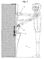
Fig. 1 shows a general view of the vending machine according to the invention; -
Fig. 2 diagrammatically shows the vending machine in a moment of use; and -
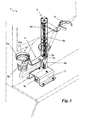
Fig. 3 is a perspective view of a device placed inside the machine. - With reference to the drawings, the vending machine or dispenser for foods and products in general according to the invention is generally denoted at 1.
- It is adapted to be used for dispensing beverages, foods, magazines or any other product suitably disposed and/or prepared inside the dispenser itself. In particular, the
vending machine 1 is adapted to dispense a selectedproduct 20 to a user 1a, based on a command/input supplied by said user. - The
vending machine 1 in known manner comprises a holding structure containing a plurality of products and defining acollection compartment 3 adapted to receive the selectedproduct 20 and having aninlet section 3a enabling picking up of the selectedproduct 20 by the user 1 a. - Preferably, the
inlet section 3a has a parallelogram-shaped profile adapted to promote extraction of theselected product 20, as better described in the following. In particular, it can be provided with a closing/opening mechanism, not shown in the figures, comprising a panel, a shutter or a plate adapted to close saidsection 3a and a motor or other actuating device adapted to move said plate so as to clear or close access to saidsection 3a. - Inside the holding structure the
vending machine 1 has, in known manner, storage systems and dispensing mechanisms, not shown in the figures, that vary depending on the type of product delivered bydispenser 1. - For instance, should
dispenser 1 be provided for dispensing previously packaged products, the holding structure would internally have a plurality of said previously packaged products and a dispensing mechanism adapted to move the selected product causing it to reach the collection compartment. Usually, the holding structure contemplates a series of shelves on which the products are disposed along orderly rows and, for each row of products, a helical element that, through rotation, causes advancing of the products of a row and then falling intocompartment 3 of the head product corresponding to theselected product 20. - Alternatively, as in the example shown in
Figs. 1-3 , thevending machine 1, in addition to dispensing the selectedproduct 20, is also adapted to prepare saidproduct 20. Therefore, the holding structure has, in known manner, a plurality of containers in which the ingredients are housed and a particular distribution/preparation mechanism selecting the necessary ingredients and preparing the selectedproduct 20. - The
vending machine 1 in addition to the aforesaid elements, comprises aninnovative delivery mechanism 4 at least partly housed inside thecollection compartment 3 and preferably fully housed in saidcompartment 3. - The
delivery mechanism 4 comprises asupport 5 adapted to define a supportingsurface 5a on which the selectedproduct 20 rests when it comes to the inside of thecollection compartment 3; actuating means 6 adapted to extract the selectedproduct 20 from thecollection compartment 3; and afastening body 7 suitable to enable constraint of thedelivery mechanism 4 atcompartment 3. - In detail, the actuating means 6 moves the
support 5 and consequently the selectedproduct 20 defining, for thedelivery mechanism 4, a configuration at rest in which thesupport 5 is inside saidcollection compartment 3, and a grip configuration in which thesupport 5 is at the outside ofcompartment 3. Therefore, said means 6moves support 5 and consequently the selectedproduct 20 by a movement having a first component substantially perpendicular to theinlet section 3a so as to vary the distance ofsupport 5 from theinlet section 3a. - Said first component can therefore be obtained through a translation along a movement plane parallel to said supporting plane of the
vending machine 1. Alternatively, this first component is preferably obtained through rotation ofsupport 5 relative to a rotation axis substantially perpendicular to the supporting plane of thevending machine 1 and, more preferably, said first rotation is substantially of 90°. - Movement of
support 5, obtained through the actuating means 6 is further characterised by the presence of a second component almost perpendicular to said supporting plane of thevending machine 1 and adapted to enable the height of the selectedproduct 20 to be varied relative to the supporting plane of the dispenser. Preferably, said second component is adapted to determine a translation along said line perpendicular to the supporting plane that is substantially equal to 200 mm. - In conclusion, the actuating means 6 is adapted to extract the
selected product 20 from thecollection compartment 3 by shiftingsupport 5 and consequently the selectedproduct 20 by a movement having both the first component and the second component. Theactuating means 6 is therefore adapted to makesupport 5 carry out a rotation-translation motion, i.e. movesupport 5 along a helical trajectory. - In said rotation-translation motion two distinct and simultaneous movements can be identified: a rotation movement defining the first component the width of which is substantially equal to 90° and which is carried out relative to an axis perpendicular to the supporting plane; and a translation movement defining the second component, along a direction almost parallel to said rotation axis.
- The actuating means 6 can therefore be provided with a working
screw 6a having a transverse extension direction, preferably perpendicular to the supporting plane ofdispenser 1 and adapted to define at least the first component of motion ofsupport 5; and guide locators including ahousing 6b rigidly secured to the fasteningbody 7, which is adapted to guide movement of saidsupport 5.Housing 6b preferably has a semicircular section so as to partly surround the workingscrew 6a; and amotor 6c adapted to move said workingscrew 6a.Housing 6b enables the above described helical motion ofsupport 5 to be defined and is therefore advantageously provided with aslit 6d adapted to come into engagement, as better described hereinafter, withsupport 5 and having a profile substantially coincident with the above described helical trajectory so as to guide movement ofsupport 5 in its rotational-translational motion, i.e. during passage of thedelivery mechanism 4 from the at-rest configuration to the grip configuration (Fig. 3 ). - The
support 5 has afirst portion 5b defining the supportingsurface 5a, a second portion 5c adapted to fastensupport 5 between the actuating means 6 andbody 7, and athird portion 5d adapted to connect said twoportions 5b and 5c. - In particular, the
first portion 5b, whendispenser 1 deals with previously packaged products such as drinks or sandwiches, consists of a suitably shaped plate or other similar element adapted to define an appropriate supportingsurface 5a. Alternatively, whendispenser 1 deals with beverages contained in aglass 20a, such as coffee and tea, thefirst portion 5b has a C-shaped profile, so as to at least partly surround and supportglass 20a, as shown inFigs. 1-3 . The second portion 5c is at least partly housed between the workingscrew 6a andhousing 6b so as to enable engagement ofsupport 5 both withscrew 6a and withslit 6d. In particular, it consists of a hollow cylindrical body having an inner wall provided with threading so that it engages with the workingscrew 6a, and anengagement tooth 5e protruding from the outer surface of the cylindrical body and suitable for engagement withslit 6d. - The
third portion 5d preferably has a substantially L-shaped profile in which the following parts can be identified: an initial plate, close to the second portion 5c, substantially parallel to the ground and of such a length that, when themechanism 4 is in the grip configuration, it enables the first portion to fully come out of thecollection compartment 3; and a final plate inclined to the former and adapted to keep thefirst portion 5a and consequently theselected product 20 in a raised position relative to the ground. -
Dispenser 1 can comprise activation means adapted to operate activation of thedelivery mechanism 4, i.e. of the means adapted to operate passage of thedelivery mechanism 4 from the at-rest configuration to the grip configuration and vice versa. In addition, said activation means is also adapted to operate the above described closing/opening mechanism of theinlet section 3a. - This activation means comprises several sensors and in particular at least one
sensor 8 adapted to automatically detect the presence of theselected product 20 on thefirst portion 5b ofsupport 5. In detail,sensor 8 is a pressure sensor, i.e. a sensor capable of detecting the presence of theselected product 20 onsupport 5 due to the weight force, i.e. the force exerted by theproduct 20 on the sensor itself. - Finally, the
vending machine 1 at the outer surface of the holding structure 2 corresponding to theinlet section 3a is provided with interface elements adapted to enable the user 1a to operate thevending machine 1. - In detail, the interface elements comprise a known
payment apparatus 9 enabling the user 1a to pay the price corresponding to the selected product; and a push-button panel 10 for selection of the desired product from a plurality of products contained in the holding structure thereby allowing said command/input to be sent to thevending machine 1. - Preferably, the push-
button panel 10 is such made as to define a pressure plane having a little inclination angle relative to the normal to the supporting plane of thevending machine 1, substantially of 3° for example. It has a series ofinscriptions 10a, each identifying one of the products present indispenser 1 and at least partly made in high relief relative to said pressure plane. - Operation of a vending machine or dispenser, described above as regards structure is the following.
- First, the
vending machine 1 has thedelivery mechanism 5 in the at-rest configuration andsupport 5 is therefore inside thecollection compartment 3. - At the moment of use, the user 1 a selects a
product 20 through the push-button panel 10, inserts the related amount through thepayment apparatus 9 and activates thevending machine 1 that prepares the selectedproduct 20 and places it onsupport 5 determining actuation of asensor 8. - If the dispenser has to provide hot beverages, as shown in
Figs. 1-3 ,dispenser 1 places theglass 20a on thefirst portion 5b close tosensors 8 and then fills theglass 20a with the selected beverage. In detail, filling ofglass 20a gives rise to an increase in weight of the glass and therefore to actuation ofsensors 8. - Once the selected
product 20 is ready,sensors 8 activate the closing/opening mechanism that will open theinlet section 3a and, substantially simultaneously, thedelivery mechanism 5 that moves from the at-rest configuration to the grip configuration. - During this passage from the at-rest configuration to the grip configuration, motor 5c sets the working
screw 6a andsupport 5 in rotation, whilehousing 6b keeps stationary. In detail, said movement ofsupport 5 relative tohousing 6b causes sliding of theengagement tooth 5e insideslit 6d and therefore the helical motion (Fig. 3 ) ofsupport 5 and of the selectedproduct 20. - The selected
product 20 substantially carries out a rotation of about 90° so that the selectedproduct 20 is extracted fromcompartment 3, as well as a translation of at least about 200 mm raising the product itself. In detail, this double movement is facilitated by the parallelogram shape of theinlet section 3a that will preventglass 20a andsupport 5 from bumping against the edge ofsection 3a. - When the
delivery mechanism 4 comes to the grip configuration, it has thefirst portion 5b and, therefore, the selectedproduct 20 fully out of thecollection compartment 3. In particular,support 5 has thethird portion 5d at least partly out of saidcompartment 3 and, more specifically, it has the second plate of the third portion 56d out of thecollection compartment 3, as shown inFigs. 1 and2 . - Once the dispenser is in the grip configuration, the
delivery mechanism 4 stops and waits for picking up of theproduct 20. - When the user 1 a picks up the
product 20 fromsupport 5,sensors 8 detect picking up and cause return ofmechanism 4 to the at-rest configuration. In detail, in this second movement, rotation of the workingscrew 6a is opposite to that of the preceding motion and, thereforesupport 5 moves along the same trajectory, but in the opposite way. - When the
delivery mechanism 4 is in the at-rest configuration, the closing/opening mechanism closes theinlet section 3a bringing dispenser 1 back to the initial state. The invention achieves important advantages. - The
vending machine 1, when the selectedproduct 20 has to be picked up, enables the latter to be in a particularly comfortable and easy position for this operation. In fact, as shown inFig. 1 ,dispenser 1 enables a user 1a to pick up the selectedproduct 20 without said user being obliged to bend and/or to kneel down. In detail, due to the presence of theinnovative delivery mechanism 4, theproduct 20 at the moment of picking it up is in an ideal position also for partly disabled people and/or people on wheelchairs. - Another advantage resides in the particular position of the push-
button panel 10 that, being slightly inclined relative to the normal to the supporting plane ofdispenser 1, offers a comfortable and practical supporting surface for the user's hand at the moment of selection. - A further advantage belonging to the
vending machine 1 is obtained due to theinscriptions 10a that, being at least partly made in high relief, enable even the blind to easily identify the desired product. - Another important advantage is obtained by virtue of the parallelogram-shaped profile of the
inlet section 3a as it prevents thesupport 5 from bumping against said profile during its movements, which will cause the selectedproduct 20 to fall. - The invention is susceptible of variations falling within the scope of the inventive idea. All of the elements described and claimed can be replaced by equivalent elements and the details, materials, shapes and sizes can be of any nature and magnitude.
Claims (6)
- A vending machine (1) for foods and products in general adapted to dispense a selected product (20) and comprising a holding structure containing a plurality of products and defining a collection compartment (3) adapted to receive said selected product (20); said collection compartment (3) having an opening section suitable to enable said selected product (2c) to come out of said collection compartment (3); a delivery mechanism (4) including a support (5) adapted to hold up said selected product (20) when said selected product (20) is in said collection compartment (3); and actuating means (6) adapted to move said support (5) by a movement having a first component parallel to the line perpendicular to said opening section (3a) in a manner adapted to define an at-rest configuration of said delivery mechanism (4) in which said support (5) is inside said collection compartment (3), and a grip configuration in which said support (5) is at least partly at the outside of said collection compartment (3) said movement of said support (5) comprising a rotation the rotation axis of which is substantially perpendicular to the supporting plane of said vending machine (1) and a second component substantially transverse to said supporting plane of said vending machine (1) and characterised in said actuating means (6) has a working screw (6a) adapted to move said support (5) in a substantially vertical direction, and guide locators for said support adapted to impose a rotational-translational motion thereto and in that said guide locators comprise a housing (6b) adapted to guide the movement of said support (5) and having a slit (6d) defining said rotational-translational motion; and wherein said support (5) has an engagement tooth (5e) suitable for engagement in said slit (6d).
- A vending machine (1) as claimed in preceding claim, wherein said actuating means (6) is housed within said collection compartment (3).
- A vending machine (1) as claimed in one or more of the preceding claims, comprising activation means adapted to control activation of at least said delivery mechanism (4).
- A vending machine (1) as claimed in the preceding claim, wherein said activation means comprises at least one sensor (8) adapted to detect the presence of said selected product (20) on said support (5).
- A vending machine (1) as claimed in one or more of the preceding claims, wherein said selected product (20) comprises a glass (20a) inside which a beverage is disposed and wherein said support (5) has a first portion (5b) with a profile adapted to at least partly surround said glass (20a).
- A vending machine (1) as claimed in the preceding claim, wherein said first portion (5b) is fully out of said collection compartment when said delivery mechanism (4) is in the grip configuration.
Applications Claiming Priority (1)
| Application Number | Priority Date | Filing Date | Title |
|---|---|---|---|
| ITMI2011A000154A IT1403912B1 (en) | 2011-02-04 | 2011-02-04 | AUTOMATIC DISTRIBUTOR OF FOOD AND PRODUCTS IN GENERAL |
Publications (2)
| Publication Number | Publication Date |
|---|---|
| EP2485196A1 EP2485196A1 (en) | 2012-08-08 |
| EP2485196B1 true EP2485196B1 (en) | 2013-06-12 |
Family
ID=43976061
Family Applications (1)
| Application Number | Title | Priority Date | Filing Date |
|---|---|---|---|
| EP20120152487 Active EP2485196B1 (en) | 2011-02-04 | 2012-01-25 | A vending machine for foods and products in general |
Country Status (2)
| Country | Link |
|---|---|
| EP (1) | EP2485196B1 (en) |
| IT (1) | IT1403912B1 (en) |
Family Cites Families (10)
| Publication number | Priority date | Publication date | Assignee | Title |
|---|---|---|---|---|
| GB2298946B (en) * | 1995-03-15 | 1998-10-14 | Gem Vending Ltd | Improvements in or relating to transport apparatus |
| IT1304276B1 (en) * | 1998-04-15 | 2001-03-13 | Ducale Macchine Da Caffe Di Sa | AUTOMATIC BEVERAGE DISPENSER IN GLASS. |
| IT1315218B1 (en) * | 1999-09-29 | 2003-02-03 | Ducale Macchine Da Caffe Di Sa | AUTOMATIC DISPENSER OF BEVERAGES IN GLASS AND RELATED METHOD FOR PREPARING THOSE |
| IT1320268B1 (en) * | 2000-10-06 | 2003-11-26 | Essegielle Srl | ESPRESSO COFFEE MACHINE. |
| ITPN20040008A1 (en) * | 2004-02-09 | 2004-05-09 | Necta Vending Solutions Spa | AUTOMATIC BEVERAGE DISPENSER WITH GLASS RELEASE DEVICE |
| JP4316398B2 (en) * | 2004-02-16 | 2009-08-19 | サンデン株式会社 | Beverage vending machine |
| EP1588981A1 (en) * | 2004-03-31 | 2005-10-26 | Gerhard Holzapfel | Process for making fresh ice creams and dispenser using this process |
| JP4149957B2 (en) * | 2004-04-20 | 2008-09-17 | サンデン株式会社 | Cup-type beverage vending machine |
| JP2006178518A (en) * | 2004-12-20 | 2006-07-06 | Sanden Corp | Beverage dispenser |
| JP4160044B2 (en) * | 2004-12-20 | 2008-10-01 | サンデン株式会社 | Beverage vending machine |
-
2011
- 2011-02-04 IT ITMI2011A000154A patent/IT1403912B1/en active
-
2012
- 2012-01-25 EP EP20120152487 patent/EP2485196B1/en active Active
Also Published As
| Publication number | Publication date |
|---|---|
| EP2485196A1 (en) | 2012-08-08 |
| ITMI20110154A1 (en) | 2012-08-05 |
| IT1403912B1 (en) | 2013-11-08 |
Similar Documents
| Publication | Publication Date | Title |
|---|---|---|
| US10820722B2 (en) | No touch utensil dispenser | |
| US7258247B2 (en) | Automated condiment dispensing system | |
| EP2571404B2 (en) | Ergonomic handle & user-interface | |
| US9149152B2 (en) | Ergonomic dispenser interface | |
| US10660456B2 (en) | Automated hygienic utensil dispenser | |
| EP3128874B1 (en) | Forward advancing cutlery dispenser | |
| US8297473B2 (en) | Cutlery dispenser and method of dispensing cutlery | |
| EP2613676B1 (en) | Ergonomic handle with user-interface | |
| US20140217112A1 (en) | Napkin Dispenser | |
| MX2014009111A (en) | Utensil dispenser. | |
| US6457605B2 (en) | Paper napkin dispenser | |
| US2919051A (en) | Bread dispenser | |
| EP2485196B1 (en) | A vending machine for foods and products in general | |
| US4133421A (en) | Coin operated packet dispensing machine | |
| US10219635B2 (en) | Nut dispenser device | |
| US4509450A (en) | Sanitary food dispenser | |
| MX2012003655A (en) | Cutlery dispenser trays. |
Legal Events
| Date | Code | Title | Description |
|---|---|---|---|
| PUAI | Public reference made under article 153(3) epc to a published international application that has entered the european phase |
Free format text: ORIGINAL CODE: 0009012 |
|
| AK | Designated contracting states |
Kind code of ref document: A1 Designated state(s): AL AT BE BG CH CY CZ DE DK EE ES FI FR GB GR HR HU IE IS IT LI LT LU LV MC MK MT NL NO PL PT RO RS SE SI SK SM TR |
|
| AX | Request for extension of the european patent |
Extension state: BA ME |
|
| 17P | Request for examination filed |
Effective date: 20121122 |
|
| GRAP | Despatch of communication of intention to grant a patent |
Free format text: ORIGINAL CODE: EPIDOSNIGR1 |
|
| GRAS | Grant fee paid |
Free format text: ORIGINAL CODE: EPIDOSNIGR3 |
|
| GRAA | (expected) grant |
Free format text: ORIGINAL CODE: 0009210 |
|
| AK | Designated contracting states |
Kind code of ref document: B1 Designated state(s): AL AT BE BG CH CY CZ DE DK EE ES FI FR GB GR HR HU IE IS IT LI LT LU LV MC MK MT NL NO PL PT RO RS SE SI SK SM TR |
|
| REG | Reference to a national code |
Ref country code: GB Ref legal event code: FG4D |
|
| REG | Reference to a national code |
Ref country code: CH Ref legal event code: EP |
|
| REG | Reference to a national code |
Ref country code: AT Ref legal event code: REF Ref document number: 616936 Country of ref document: AT Kind code of ref document: T Effective date: 20130615 |
|
| REG | Reference to a national code |
Ref country code: CH Ref legal event code: NV Representative=s name: BOVARD AG, CH |
|
| REG | Reference to a national code |
Ref country code: IE Ref legal event code: FG4D |
|
| REG | Reference to a national code |
Ref country code: DE Ref legal event code: R096 Ref document number: 602012000078 Country of ref document: DE Effective date: 20130808 |
|
| PG25 | Lapsed in a contracting state [announced via postgrant information from national office to epo] |
Ref country code: FI Free format text: LAPSE BECAUSE OF FAILURE TO SUBMIT A TRANSLATION OF THE DESCRIPTION OR TO PAY THE FEE WITHIN THE PRESCRIBED TIME-LIMIT Effective date: 20130612 Ref country code: GR Free format text: LAPSE BECAUSE OF FAILURE TO SUBMIT A TRANSLATION OF THE DESCRIPTION OR TO PAY THE FEE WITHIN THE PRESCRIBED TIME-LIMIT Effective date: 20130913 Ref country code: NO Free format text: LAPSE BECAUSE OF FAILURE TO SUBMIT A TRANSLATION OF THE DESCRIPTION OR TO PAY THE FEE WITHIN THE PRESCRIBED TIME-LIMIT Effective date: 20130912 Ref country code: LT Free format text: LAPSE BECAUSE OF FAILURE TO SUBMIT A TRANSLATION OF THE DESCRIPTION OR TO PAY THE FEE WITHIN THE PRESCRIBED TIME-LIMIT Effective date: 20130612 Ref country code: SI Free format text: LAPSE BECAUSE OF FAILURE TO SUBMIT A TRANSLATION OF THE DESCRIPTION OR TO PAY THE FEE WITHIN THE PRESCRIBED TIME-LIMIT Effective date: 20130612 Ref country code: SE Free format text: LAPSE BECAUSE OF FAILURE TO SUBMIT A TRANSLATION OF THE DESCRIPTION OR TO PAY THE FEE WITHIN THE PRESCRIBED TIME-LIMIT Effective date: 20130612 Ref country code: ES Free format text: LAPSE BECAUSE OF FAILURE TO SUBMIT A TRANSLATION OF THE DESCRIPTION OR TO PAY THE FEE WITHIN THE PRESCRIBED TIME-LIMIT Effective date: 20130923 |
|
| REG | Reference to a national code |
Ref country code: AT Ref legal event code: MK05 Ref document number: 616936 Country of ref document: AT Kind code of ref document: T Effective date: 20130612 |
|
| REG | Reference to a national code |
Ref country code: NL Ref legal event code: VDEP Effective date: 20130612 |
|
| REG | Reference to a national code |
Ref country code: LT Ref legal event code: MG4D |
|
| PG25 | Lapsed in a contracting state [announced via postgrant information from national office to epo] |
Ref country code: HR Free format text: LAPSE BECAUSE OF FAILURE TO SUBMIT A TRANSLATION OF THE DESCRIPTION OR TO PAY THE FEE WITHIN THE PRESCRIBED TIME-LIMIT Effective date: 20130612 Ref country code: BG Free format text: LAPSE BECAUSE OF FAILURE TO SUBMIT A TRANSLATION OF THE DESCRIPTION OR TO PAY THE FEE WITHIN THE PRESCRIBED TIME-LIMIT Effective date: 20130912 Ref country code: RS Free format text: LAPSE BECAUSE OF FAILURE TO SUBMIT A TRANSLATION OF THE DESCRIPTION OR TO PAY THE FEE WITHIN THE PRESCRIBED TIME-LIMIT Effective date: 20130612 |
|
| PG25 | Lapsed in a contracting state [announced via postgrant information from national office to epo] |
Ref country code: LV Free format text: LAPSE BECAUSE OF FAILURE TO SUBMIT A TRANSLATION OF THE DESCRIPTION OR TO PAY THE FEE WITHIN THE PRESCRIBED TIME-LIMIT Effective date: 20130612 |
|
| PG25 | Lapsed in a contracting state [announced via postgrant information from national office to epo] |
Ref country code: EE Free format text: LAPSE BECAUSE OF FAILURE TO SUBMIT A TRANSLATION OF THE DESCRIPTION OR TO PAY THE FEE WITHIN THE PRESCRIBED TIME-LIMIT Effective date: 20130612 Ref country code: PT Free format text: LAPSE BECAUSE OF FAILURE TO SUBMIT A TRANSLATION OF THE DESCRIPTION OR TO PAY THE FEE WITHIN THE PRESCRIBED TIME-LIMIT Effective date: 20131014 Ref country code: AT Free format text: LAPSE BECAUSE OF FAILURE TO SUBMIT A TRANSLATION OF THE DESCRIPTION OR TO PAY THE FEE WITHIN THE PRESCRIBED TIME-LIMIT Effective date: 20130612 Ref country code: SK Free format text: LAPSE BECAUSE OF FAILURE TO SUBMIT A TRANSLATION OF THE DESCRIPTION OR TO PAY THE FEE WITHIN THE PRESCRIBED TIME-LIMIT Effective date: 20130612 Ref country code: IS Free format text: LAPSE BECAUSE OF FAILURE TO SUBMIT A TRANSLATION OF THE DESCRIPTION OR TO PAY THE FEE WITHIN THE PRESCRIBED TIME-LIMIT Effective date: 20131012 Ref country code: BE Free format text: LAPSE BECAUSE OF FAILURE TO SUBMIT A TRANSLATION OF THE DESCRIPTION OR TO PAY THE FEE WITHIN THE PRESCRIBED TIME-LIMIT Effective date: 20130612 Ref country code: CZ Free format text: LAPSE BECAUSE OF FAILURE TO SUBMIT A TRANSLATION OF THE DESCRIPTION OR TO PAY THE FEE WITHIN THE PRESCRIBED TIME-LIMIT Effective date: 20130612 |
|
| PG25 | Lapsed in a contracting state [announced via postgrant information from national office to epo] |
Ref country code: NL Free format text: LAPSE BECAUSE OF FAILURE TO SUBMIT A TRANSLATION OF THE DESCRIPTION OR TO PAY THE FEE WITHIN THE PRESCRIBED TIME-LIMIT Effective date: 20130612 Ref country code: PL Free format text: LAPSE BECAUSE OF FAILURE TO SUBMIT A TRANSLATION OF THE DESCRIPTION OR TO PAY THE FEE WITHIN THE PRESCRIBED TIME-LIMIT Effective date: 20130612 Ref country code: RO Free format text: LAPSE BECAUSE OF FAILURE TO SUBMIT A TRANSLATION OF THE DESCRIPTION OR TO PAY THE FEE WITHIN THE PRESCRIBED TIME-LIMIT Effective date: 20130612 |
|
| PLBE | No opposition filed within time limit |
Free format text: ORIGINAL CODE: 0009261 |
|
| STAA | Information on the status of an ep patent application or granted ep patent |
Free format text: STATUS: NO OPPOSITION FILED WITHIN TIME LIMIT |
|
| PG25 | Lapsed in a contracting state [announced via postgrant information from national office to epo] |
Ref country code: DK Free format text: LAPSE BECAUSE OF FAILURE TO SUBMIT A TRANSLATION OF THE DESCRIPTION OR TO PAY THE FEE WITHIN THE PRESCRIBED TIME-LIMIT Effective date: 20130612 |
|
| 26N | No opposition filed |
Effective date: 20140313 |
|
| REG | Reference to a national code |
Ref country code: DE Ref legal event code: R097 Ref document number: 602012000078 Country of ref document: DE Effective date: 20140313 |
|
| PG25 | Lapsed in a contracting state [announced via postgrant information from national office to epo] |
Ref country code: LU Free format text: LAPSE BECAUSE OF FAILURE TO SUBMIT A TRANSLATION OF THE DESCRIPTION OR TO PAY THE FEE WITHIN THE PRESCRIBED TIME-LIMIT Effective date: 20140125 |
|
| REG | Reference to a national code |
Ref country code: IE Ref legal event code: MM4A |
|
| PG25 | Lapsed in a contracting state [announced via postgrant information from national office to epo] |
Ref country code: IE Free format text: LAPSE BECAUSE OF NON-PAYMENT OF DUE FEES Effective date: 20140125 |
|
| PG25 | Lapsed in a contracting state [announced via postgrant information from national office to epo] |
Ref country code: MC Free format text: LAPSE BECAUSE OF FAILURE TO SUBMIT A TRANSLATION OF THE DESCRIPTION OR TO PAY THE FEE WITHIN THE PRESCRIBED TIME-LIMIT Effective date: 20130612 |
|
| REG | Reference to a national code |
Ref country code: FR Ref legal event code: PLFP Year of fee payment: 5 |
|
| PG25 | Lapsed in a contracting state [announced via postgrant information from national office to epo] |
Ref country code: MT Free format text: LAPSE BECAUSE OF FAILURE TO SUBMIT A TRANSLATION OF THE DESCRIPTION OR TO PAY THE FEE WITHIN THE PRESCRIBED TIME-LIMIT Effective date: 20130612 |
|
| PG25 | Lapsed in a contracting state [announced via postgrant information from national office to epo] |
Ref country code: SM Free format text: LAPSE BECAUSE OF FAILURE TO SUBMIT A TRANSLATION OF THE DESCRIPTION OR TO PAY THE FEE WITHIN THE PRESCRIBED TIME-LIMIT Effective date: 20130612 |
|
| PG25 | Lapsed in a contracting state [announced via postgrant information from national office to epo] |
Ref country code: CY Free format text: LAPSE BECAUSE OF FAILURE TO SUBMIT A TRANSLATION OF THE DESCRIPTION OR TO PAY THE FEE WITHIN THE PRESCRIBED TIME-LIMIT Effective date: 20130612 |
|
| PG25 | Lapsed in a contracting state [announced via postgrant information from national office to epo] |
Ref country code: HU Free format text: LAPSE BECAUSE OF FAILURE TO SUBMIT A TRANSLATION OF THE DESCRIPTION OR TO PAY THE FEE WITHIN THE PRESCRIBED TIME-LIMIT; INVALID AB INITIO Effective date: 20120125 Ref country code: TR Free format text: LAPSE BECAUSE OF FAILURE TO SUBMIT A TRANSLATION OF THE DESCRIPTION OR TO PAY THE FEE WITHIN THE PRESCRIBED TIME-LIMIT Effective date: 20130612 |
|
| REG | Reference to a national code |
Ref country code: FR Ref legal event code: PLFP Year of fee payment: 6 |
|
| REG | Reference to a national code |
Ref country code: FR Ref legal event code: PLFP Year of fee payment: 7 |
|
| PG25 | Lapsed in a contracting state [announced via postgrant information from national office to epo] |
Ref country code: MK Free format text: LAPSE BECAUSE OF FAILURE TO SUBMIT A TRANSLATION OF THE DESCRIPTION OR TO PAY THE FEE WITHIN THE PRESCRIBED TIME-LIMIT Effective date: 20130612 |
|
| PG25 | Lapsed in a contracting state [announced via postgrant information from national office to epo] |
Ref country code: AL Free format text: LAPSE BECAUSE OF FAILURE TO SUBMIT A TRANSLATION OF THE DESCRIPTION OR TO PAY THE FEE WITHIN THE PRESCRIBED TIME-LIMIT Effective date: 20130612 |
|
| PGFP | Annual fee paid to national office [announced via postgrant information from national office to epo] |
Ref country code: DE Payment date: 20200129 Year of fee payment: 9 |
|
| PGFP | Annual fee paid to national office [announced via postgrant information from national office to epo] |
Ref country code: CH Payment date: 20200127 Year of fee payment: 9 |
|
| REG | Reference to a national code |
Ref country code: DE Ref legal event code: R119 Ref document number: 602012000078 Country of ref document: DE |
|
| REG | Reference to a national code |
Ref country code: CH Ref legal event code: PL |
|
| PG25 | Lapsed in a contracting state [announced via postgrant information from national office to epo] |
Ref country code: LI Free format text: LAPSE BECAUSE OF NON-PAYMENT OF DUE FEES Effective date: 20210131 Ref country code: DE Free format text: LAPSE BECAUSE OF NON-PAYMENT OF DUE FEES Effective date: 20210803 Ref country code: CH Free format text: LAPSE BECAUSE OF NON-PAYMENT OF DUE FEES Effective date: 20210131 |
|
| PGFP | Annual fee paid to national office [announced via postgrant information from national office to epo] |
Ref country code: GB Payment date: 20220125 Year of fee payment: 11 |
|
| PGFP | Annual fee paid to national office [announced via postgrant information from national office to epo] |
Ref country code: FR Payment date: 20220120 Year of fee payment: 11 |
|
| P01 | Opt-out of the competence of the unified patent court (upc) registered |
Effective date: 20230607 |
|
| GBPC | Gb: european patent ceased through non-payment of renewal fee |
Effective date: 20230125 |
|
| PG25 | Lapsed in a contracting state [announced via postgrant information from national office to epo] |
Ref country code: GB Free format text: LAPSE BECAUSE OF NON-PAYMENT OF DUE FEES Effective date: 20230125 |
|
| PG25 | Lapsed in a contracting state [announced via postgrant information from national office to epo] |
Ref country code: FR Free format text: LAPSE BECAUSE OF NON-PAYMENT OF DUE FEES Effective date: 20230131 |
|
| PGFP | Annual fee paid to national office [announced via postgrant information from national office to epo] |
Ref country code: IT Payment date: 20241126 Year of fee payment: 14 |