EP1672598A2 - Beverage dispenser - Google Patents
Beverage dispenser Download PDFInfo
- Publication number
- EP1672598A2 EP1672598A2 EP05257555A EP05257555A EP1672598A2 EP 1672598 A2 EP1672598 A2 EP 1672598A2 EP 05257555 A EP05257555 A EP 05257555A EP 05257555 A EP05257555 A EP 05257555A EP 1672598 A2 EP1672598 A2 EP 1672598A2
- Authority
- EP
- European Patent Office
- Prior art keywords
- cup
- holding portion
- holder
- port
- overload
- Prior art date
- Legal status (The legal status is an assumption and is not a legal conclusion. Google has not performed a legal analysis and makes no representation as to the accuracy of the status listed.)
- Withdrawn
Links
- 235000013361 beverage Nutrition 0.000 title claims abstract description 51
- 238000000034 method Methods 0.000 claims abstract description 25
- 238000001514 detection method Methods 0.000 claims description 32
- 239000000463 material Substances 0.000 claims description 20
- 230000003028 elevating effect Effects 0.000 claims description 2
- 239000004973 liquid crystal related substance Substances 0.000 description 13
- 238000010586 diagram Methods 0.000 description 12
- 230000005856 abnormality Effects 0.000 description 8
- 230000033001 locomotion Effects 0.000 description 6
- 230000007246 mechanism Effects 0.000 description 4
- XLYOFNOQVPJJNP-UHFFFAOYSA-N water Substances O XLYOFNOQVPJJNP-UHFFFAOYSA-N 0.000 description 4
- 230000002093 peripheral effect Effects 0.000 description 2
- 239000000843 powder Substances 0.000 description 2
- 238000009877 rendering Methods 0.000 description 2
- 230000005540 biological transmission Effects 0.000 description 1
- 238000006243 chemical reaction Methods 0.000 description 1
- 239000006071 cream Substances 0.000 description 1
- 239000007788 liquid Substances 0.000 description 1
- 230000007257 malfunction Effects 0.000 description 1
- 238000005259 measurement Methods 0.000 description 1
- 239000008267 milk Substances 0.000 description 1
- 235000013336 milk Nutrition 0.000 description 1
- 210000004080 milk Anatomy 0.000 description 1
- 238000002156 mixing Methods 0.000 description 1
- 239000010893 paper waste Substances 0.000 description 1
Images


Classifications
-
- G—PHYSICS
- G07—CHECKING-DEVICES
- G07F—COIN-FREED OR LIKE APPARATUS
- G07F13/00—Coin-freed apparatus for controlling dispensing or fluids, semiliquids or granular material from reservoirs
- G07F13/10—Coin-freed apparatus for controlling dispensing or fluids, semiliquids or granular material from reservoirs with associated dispensing of containers, e.g. cups or other articles
Definitions
- the present invention relates to a beverage dispenser for providing a purchaser with a cup in which a beverage is filled.
- This kind of a beverage dispenser contains beverage generating devices including a cup carrier, a water cleaner, a hot-water generator, material storehouses, a coffee extractor, an ice maker, an agitator and so on.
- the beverage dispenser generates a beverage by a predetermined procedure and provides a purchaser with a cup in which the beverage is filled based on money dropped in and selection of the beverage.
- a conventional beverage dispenser has a cup mount provided an inside of a cup port and places the cup in which the beverage is filled on the cup mount. Therefore, the purchaser needs to put a hand in the cup port and take out the cup after manually opening the door or automatically opening the door.
- a height position of the cup port is predetermined based on average height. Therefore, it happens that the cup gets hooked on an edge of the cup port and the beverage in the cup gets spilt in the case where the purchaser shorter or taller than the average height puts a hand in the cup port and takes out the cup.
- An object of the present invention is to provide a beverage dispenser which has simplified a purchaser's operation for taking out a cup by placing the cup in which a beverage is filled on a cup mount provided at an outside of a cup port.
- the beverage dispenser comprises: a cup port provided at a front surface of a body; a cup mount provided at an outside of the cup port; a cup holder including a cup holding portion, an internal diameter of the cup holding portion slightly smaller than a maximum external diameter of a cup in an external form like an inverted truncated cone, a right-to-left space of an opening of the cup holding portion slightly larger than a minimum external diameter of the cup, the cup holder capable of holding the cup with the cup holding portion; a holder mover capable of moving the cup holder at least forward and backward and upward and downward; and cup carryout control means for operating the cup holder so that the holding portion holding the cup is advanced from an inside of the cup port to the outside thereof to locate the holding portion above the cup mount, the cop holding portion is lowered from an above position by a predetermined distance to place the cup on the cup mount in process of lowering, and the cup holding portion is retreated from a lowered position to the inside of the cup port to leave the cup on the cup
- this beverage dispenser it is possible to provide the cup in which the beverage is filled in front of the purchaser by a series of cup carryout operations of moving the cup holder to advance the cup holding portion holding the cup in which the beverage is filled from the inside of the cup port to the outside thereof to locate the cup holding portion above the cup mount, lower the cup holding portion from the above position by a predetermined distance to place the cup on the cup mount in process of lowering, and retreat the cup holding portion from the lowered position to the inside of the cup port to leave the cup on the cup mount. Therefore, it is possible to simplify the purchaser's operation for taking out the cup by rendering the conventional operation of putting a hand in the cup port and taking out the cup unnecessary.
- FIGS. 1 to 15 show an embodiment of the present invention.
- the following description indicates top of FIG. 1 as the top, bottom of FIG. 1 as the bottom, left of FIG. 1 as the left, right of FIG. 1 as the right, a front side of FIG. 1 as the front, and a depth side of FIG. 1 as the back.
- a body 1 shown in FIG. 1 comprises a cabinet (not shown) having a front opening and a door (no reference numeral) openable and closable provided at the front opening of the cabinet.
- the body 1 contains beverage generating devices and a holder mover described later.
- the beverage generating devices includes a cup carrier, a water cleaner, a hot-water generator, material storehouses, a coffee extractor, an ice maker, an agitator and so on.
- a bill slot 2 At a front surface of the door of the body 1, there are a bill slot 2, a coin slot 3, a return lever 4, a coin return opening 5, a liquid crystal display 6 and multiple operation buttons 7 arranged on the right and left of the liquid crystal display 6. It is also possible to use a known display such as a CRT (Cathode Ray Tube) display or a PDP (Plasma Display Panel) instead of the liquid crystal display 6.
- a CRT Cathode Ray Tube
- PDP Plasma Display Panel
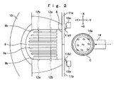
- cup port 8 in a vertically long rectangular form, a cup mount 9 provided at an outside of the cup port 8 and a simple table 10 provided under the cup mount 9. Furthermore, on the backside of the cup port 8, there are a pair of right and left slide doors 11a, 11b for opening and closing the cup port 8.
- the cup mount 9 has sufficient area to have a cup C mentioned later mounted thereon, and also has multiple convex streaks 9a at intervals rightward and leftward.
- each of the object detection sensors 12 there are two object detection sensors 12 (refer to FIG. 4) for detecting whether or not there is an object on the cup mount 9 with spacing before and after.
- each of the object detection sensors 12 it is possible to use a transmission photosensor configured by a light emitting element 12a such as a photodiode and a light receiving element 12b such as a phototransistor for instance.
- the light emitting elements 12a of the photosensors are provided on mutually different wall surfaces as shown in FIG. 2 so as not to cause a malfunction by having light from the light emitting element 12a of one photosensor incident on the light receiving element 12b of the other photosensor.
- the number of the object detection sensors may also be one, or three or more.
- the pair of right and left slide doors 11a, 11b are normally closing the cup port 8, and open the cup port 8 on carrying out the cup C by moving rightward and leftward as if separating from each other.
- means for opening and closing the slide doors 11a, 11b it is possible to adopt a mechanism comprising parts such as a spring for biasing the slide doors 11a, 11b to come close to each other and keeping a state of closing, a pressed surface such as a curved surface provided symmetrically on the backside of each of the slide doors 11a, 11b, and a roller for pressing the pressed surface of each of the slide doors 11a, 11b by advancing a cup holder 14 to operate the slide doors 11a, 11b to separate from each other.
- closing detection sensors 13a, 13b for detecting the closing of the slide doors 11a, 11b.
- microswitches may be used for the closing detection sensors 13a, 13b.
- projections 11a1, 11b1 for operating the microswitches at door closing positions are provided at the tops of the slide doors 11a, 11b as shown in FIG. 2.
- the cup C is in the external form like an inverted truncated cone, and has circular ribs on its top peripheral edge.
- the cup C consists of an inflammable material such as paper, where an external diameter of the circular rib existing on the top edge is largest and the external diameter on the bottom edge is smallest.
- a large number of the cups C are stacked and housed in the cup carrier, and are dropped and carried out one by one from the cup carrier.
- the cup holder 14 has a cup holding portion 14a of which top surface is approximately C-shaped on its tip.
- An internal diameter L1 (refer to FIG. 12) of the cup holding portion 14a is slightly smaller than a maximum external diameter of the cup C, and a right-to-left space L2 (refer to FIG. 12) of an opening of the cup holding portion 14a is slightly larger than a minimum external diameter of the cup C.
- the cup C if the cup C is dropped from above the cup holding portion 14a, the cup C stops in a state of having the circular rib engaged with an inner peripheral edge of the cup holding portion 14a so as to be held by the cup holding portion 14a.
- the maximum external diameter of the cup C is the external diameter of the circular rib.
- similar automatic holding is also possible by determining a held part of the cup C in a lower part than the circular rib and setting the internal diameter L1 of the cup holding portion 14a slightly smaller than the external diameter of the held part.
- the cup holder 14 can be moved by an unshown holder mover in ⁇ X direction (rightward and leftward), ⁇ Y direction (forward and backward) and ⁇ Z direction (upward and downward) shown in FIGS. 2 and 3, that is, three-dimensional movement in the body 1.
- the holder mover comprises an X-axis motor Mx, a Y-axis motor My and a Z-axis motor Mz (refer to FIG. 4) and motion converting mechanisms (not shown) for each axis.
- Each of the motion converting mechanisms converts rotary motion of each motor to linear motion and conveying it to the cup holder 14 by parts such as a ball screw, a nut engaged with the ball screw and a linear guide. Concerning a cup carryout operation described later, it is sufficient if the holder mover can move the cup holder 14 at least in the ⁇ Y direction and ⁇ Z direction.
- a control portion 21 shown in FIG. 4 has a microcomputer configuration.
- a memory of the control portion 21 stores a program related to beverage blending before carrying out the cup C, a program related to the cup carryout operation shown in FIGS. 14 and 15, character data and image data to be displayed on the liquid crystal display 6, reference current data for overload determination and the like.
- An object detecting portion 22 sends detection signals of the two object detection sensors 12 to the control portion 21.
- a door opening and closing detecting portion 23 sends the detection signals of the detection sensors 13a, 13b to the control portion 21.
- An inside temperature detecting portion 24 sends the detection signals of a temperature sensor 27 such as a thermistor placed in the body 1 to the control portion 21.
- a holder driving portion 25 sends an individual motor driving signal to each of the X-axis motor Mx, Y-axis motor My and Z-axis motor Mz of the holder mover based on a control signal from the control portion 21 and detects a current passing in the Z-axis motor Mz so as to send the detection signals to the control portion 21.
- a display driving portion 26 sends an image display signal to the liquid crystal display 6 based on a control signal and an image signal from the control portion 21.
- Salable beverage kinds and an operation method are displayed on the liquid crystal display 6. Therefore, according to the indication on the liquid crystal display 6, a purchaser selects a beverage with the operation buttons 7 and drops in the money required to purchase the beverage.
- the cup holder 14 moves to a carryout position of the cup carrier so as to receive the cup C dropped and carried from the cup carrier.
- the internal diameter L1 (refer to FIG. 12) of the cup holding portion 14a is slightly smaller than the maximum external diameter of the cup C, and so if the cup C is dropped from above the cup holding portion 14a, the cup C is automatically held by the cup holding portion 14a.
- the cup holder 14 After receiving the cup C, the cup holder 14 moves in the body 1 according to a predetermined procedure, and a desired beverage is generated in the cup C in the moving process. For instance, in the case where coffee with cream and sugar is selected as the beverage, the cup holder 14 moves in the body 1 according to the predetermined procedure so as to have sugar powder and milk powder dropped into the cup C from the material storehouses, coffee liquid extracted by the coffee extractor filled in the cup C and agitated.
- the cup holder 14 holding the cup C in which the beverage is filled moves to a standby position set up an inside of the cup port 8 and stops as shown in FIGS. 2 and 3 (step S1 of FIG. 14).
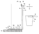
- step S2 of FIG. 14 determines whether or not there is an extraneous material EM on the cup mount 9, which becomes an obstacle on placing the cup C on the cup mount 9, based on the detection signals of the object detection sensors 12 (step S2 of FIG. 14).
- a warning message such as "Remove the extraneous material on the cup mount” is displayed on the liquid crystal display 6 or a buzz is generated or both are performed to give a warning for prompting removal of the extraneous material (step S4 of FIG. 14). If the extraneous material is not removed after elapse of a predetermined time from the warning, it moves on to a step S18 to perform a carryout abnormality process (step S5 of FIG. 14).
- the carryout abnormality process in this case indicates a process for performing an error display on the liquid crystal display 6 and stopping the cup carryout operation to put an end to selling of the beverage.
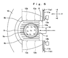
- the cup holder 14 is advanced from the standby position by a predetermined distance in the +Y direction.
- the slide doors 11a, 11b are moved rightward and leftward to separate from each other so as to open the cup port 8 (step S5 of FIG. 14).
- the cup C held by the cup holding portion 14a of the cup holder 14 advances from the inside of the cup port 8 to the outside thereof to be positioned above the cup mount 9.
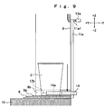
- the cup holder 14 holding the cup C in which the beverage is filled is lowered from an above position by a predetermined distance in the -Z direction (step S6 of FIG. 14).
- the lowering distance of the cup holder 14 is set up based on the height position at which the right-to-left space L2 (refer to FIG. 12) of the opening of the cup holding portion 14a becomes larger than the external diameter of the cup C.
- the cup C is held by a hand H of the purchaser while the cup holder 14 is lowering halfway and the hand H is sandwiched between the cup holder 14 and the cup mount 9, it is determined that there is the overload because the variation Ic becomes the stipulated value or higher.
- the warning message such as "Release your hand from the cup” is displayed on the liquid crystal display 6 or a buzz is generated or both are performed to give the warning for prompting the removal of the overload (step S9 of FIG. 14).
- the cup holder 14 is elevated and stopped in an elevated state for a predetermined time (waiting time) as shown in FIG.
- step S10 and S11 of FIG. 14 The processes of the steps S9 to S11 are retried by a predetermined number of times. If the abnormality is not resolved by retrying them the predetermined number of times, it moves on to the step S18 to perform the carryout abnormality process (step S8 of FIG. 14).
- the carryout abnormality process in this case indicates the process for performing an error display on the liquid crystal display 6 and retreating the cup holder 14 to the inside of the cup port 8 to put an end to selling of the beverage thereafter.
- step S7 it is determined whether or not the cup C is placed on the cup mount 9 by the lowering of the cup holder 14 based on the detection signals of the object detection sensors 12 (step S12 of FIG. 14).
- the cup holder 14 is retreated from a lowered position by a predetermined distance in the -Y direction after waiting until the cup holder 14 lowers by the predetermined distance so as to move the cup holding portion 14a from the outside of the cup port 8 to the inside thereof as shown in FIGS. 12 and 13 (step S13 of FIG. 14).
- the right-to-left space L2 (refer to FIG. 12) of the opening of the cup holding portion 14a is slightly larger than the minimum external diameter of the cup C. Therefore, if the cup holder 14 is retreated after lowering the cup holder 14, it is possible to release the holding by the cup holding portion 14a so as to leave the cup C in which the beverage is filled on the cup mount 9.
- the operation of advancing the cup holder 14 by the predetermined distance in the +Y direction from a retreated position and retreating it by the predetermined distance in the -Y direction is retried a predetermined number of times. If the abnormality is not resolved by retrying them the predetermined number of times, it moves on to the step S18 to perform the carryout abnormality process (steps S15 and 16 of FIG. 14).
- the carryout abnormality process in this case indicates the process for performing an error display on the liquid crystal display 6 and retreating the cup holder 14 to the inside of the cup port 8 to put an end to selling of the beverage thereafter.
- step S14 If determined that the slide doors 11a, 11b are normally closed in the step S14, it moves on to a step S17 to perform a carryout ending process.
- the carryout ending process in this case indicates a process for returning the cup holder 14 moved to the inside of the cup port 8 to an initial position before beverage generation.
- the actual current Ia passing through the Z-axis motor Mz on lowering the cup holder 14 in the step S6 changes subtly according to an operation environment of the Z-axis motor Mz. To follow this change, it is desirable to measure and update the reference current Is for the overload determination in adequate timing.
- the update timing may be every predetermined time.
- the operation environment of the Z-axis motor Mz is apt to change when the power of the beverage dispenser is turned on (step ST2 of FIG. 15), when the door of the body 1 is opened or closed (step ST3 of FIG. 15), and when the inside temperature changes (step ST4 of FIG. 15).
- the current passing through the Z-axis motor Mz is measured on lowering the cup holder 14 in timing of each of the cases including the case where the reference current ls has not been measured so as to store (including rewriting) the digital value thereof as the reference current Is in the memory and set a measured flag (steps ST1, ST5 and ST6 of FIG. 15).
- the cup C in which the beverage is filled before the purchaser by a series of cup carryout operations of moving the cup holder 14 to advance the cup holding portion 14a holding the cup C in which the beverage is filled from the inside of the cup port 8 to the outside thereof to locate the cup holding portion 14a above the cup mount 9, lower the cup holding portion 14a from the above position by a predetermined distance to place the cup C on the cup mount 9 in process of lowering, and retreat the cup holding portion 14a from the lowered position to the inside of the cup port 8 to leave the cup on the cup mount 9. Therefore, it is possible to remarkably simplify the purchaser's operation for taking out the cup by rendering the conventional operation of putting the hand in the cup port and taking out the cup unnecessary.
- the operation of elevating and lowering the cup holder 14 is repeated the predetermined number of times until determined that there is no overload. Therefore, it is possible to remove the overload precisely by using this retry operation time.
- the overload is detected based on comparison between the current passing through the Z-axis motor Mz on lowering the cup holder 14 and the predetermined reference current. Therefore, it is possible to detect the overload accurately and simply.
- the reference current is measured and updated in predetermined timing. Therefore, even in the case where the operation environment of the Z-axis motor Mz changes, it is possible to perform adequate overload detection according to the operation environment.
- cup port 8 in the vertically long rectangular form.
- the form thereof is not limited in particular as long as it allows the series of cup carryout operations.
- the two slide doors 11a, 11b movable to the right and left are shown as the door for opening and closing the cup port 8.
- the door may also be configured by two biparting pivoted doors rotatable by using each margin as a pivot, one slide door movable to the right and left, one slide door movable up and down or one pivoted door rotatable by using one margin each on the right and left as a pivot.
- the photosensors were indicated as the object detection sensors 12. However, the sensor other than the photosensor may also be used if capable of the same object detection.
- microswitches were indicated as the closing detection sensors 13a, 13b.
- the sensor other than the microswitch may also be used if capable of the same closing detection.
Landscapes
- Physics & Mathematics (AREA)
- General Physics & Mathematics (AREA)
- Beverage Vending Machines With Cups, And Gas Or Electricity Vending Machines (AREA)
Abstract
A beverage dispenser operates a cup holder (14) to advance a cup holding portion (14a) holding a cup (C) in which a beverage is filled from an inside of a cup port (8) to an outside thereof to locate it above a cup mount (9), lower the cup holding portion (14a) from a above position by a predetermined distance to place the cup (C) on the cup mount (9) in process of lowering, and retreat the cup holding portion (14a) from a lowered position to the inside of the cup port (8) to leave the cup (C) on the cup mount (9).
Description
- The present invention relates to a beverage dispenser for providing a purchaser with a cup in which a beverage is filled.
- This kind of a beverage dispenser contains beverage generating devices including a cup carrier, a water cleaner, a hot-water generator, material storehouses, a coffee extractor, an ice maker, an agitator and so on. The beverage dispenser generates a beverage by a predetermined procedure and provides a purchaser with a cup in which the beverage is filled based on money dropped in and selection of the beverage.
- A conventional beverage dispenser has a cup mount provided an inside of a cup port and places the cup in which the beverage is filled on the cup mount. Therefore, the purchaser needs to put a hand in the cup port and take out the cup after manually opening the door or automatically opening the door.
- A height position of the cup port is predetermined based on average height. Therefore, it happens that the cup gets hooked on an edge of the cup port and the beverage in the cup gets spilt in the case where the purchaser shorter or taller than the average height puts a hand in the cup port and takes out the cup.
- An object of the present invention is to provide a beverage dispenser which has simplified a purchaser's operation for taking out a cup by placing the cup in which a beverage is filled on a cup mount provided at an outside of a cup port.
- To attain the object, the beverage dispenser comprises: a cup port provided at a front surface of a body; a cup mount provided at an outside of the cup port; a cup holder including a cup holding portion, an internal diameter of the cup holding portion slightly smaller than a maximum external diameter of a cup in an external form like an inverted truncated cone, a right-to-left space of an opening of the cup holding portion slightly larger than a minimum external diameter of the cup, the cup holder capable of holding the cup with the cup holding portion; a holder mover capable of moving the cup holder at least forward and backward and upward and downward; and cup carryout control means for operating the cup holder so that the holding portion holding the cup is advanced from an inside of the cup port to the outside thereof to locate the holding portion above the cup mount, the cop holding portion is lowered from an above position by a predetermined distance to place the cup on the cup mount in process of lowering, and the cup holding portion is retreated from a lowered position to the inside of the cup port to leave the cup on the cup mount.
- According to this beverage dispenser, it is possible to provide the cup in which the beverage is filled in front of the purchaser by a series of cup carryout operations of moving the cup holder to advance the cup holding portion holding the cup in which the beverage is filled from the inside of the cup port to the outside thereof to locate the cup holding portion above the cup mount, lower the cup holding portion from the above position by a predetermined distance to place the cup on the cup mount in process of lowering, and retreat the cup holding portion from the lowered position to the inside of the cup port to leave the cup on the cup mount. Therefore, it is possible to simplify the purchaser's operation for taking out the cup by rendering the conventional operation of putting a hand in the cup port and taking out the cup unnecessary.
- The object, other objects, features and advantages of the present invention will be clarified by the following description and the attached drawings.
- In the Drawings:
- FIG. 1 is a front view of a beverage dispenser showing an embodiment of the present invention;
- FIG. 2 is a top view of a cup port of FIG. 1;
- FIG. 3 is a longitudinal section of FIG. 2;
- FIG. 4 is a block diagram of a control system;
- FIG. 5 is an explanatory diagram of a cup carryout operation;
- FIG. 6 is an explanatory diagram of the cup carryout operation;
- FIG. 7 is an explanatory diagram of the cup carryout operation;
- FIG. 8 is an explanatory diagram of the cup carryout operation;
- FIG. 9 is an explanatory diagram of the cup carryout operation;
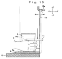
- FIG. 10 is an explanatory diagram of the cup carryout operation;
- FIG. 11 is an explanatory diagram of the cup carryout operation;
- FIG. 12 is an explanatory diagram of the cup carryout operation;
- FIG. 13 is an explanatory diagram of the cup carryout operation;
- FIG. 14 is a diagram showing a program flow related to cup carryout control; and
- FIG. 15 is a diagram showing a program flow related to reference current measurement.
- FIGS. 1 to 15 show an embodiment of the present invention. The following description indicates top of FIG. 1 as the top, bottom of FIG. 1 as the bottom, left of FIG. 1 as the left, right of FIG. 1 as the right, a front side of FIG. 1 as the front, and a depth side of FIG. 1 as the back.
- First, an overall configuration of a beverage dispenser will be described by referring to FIGS. 1 to 4.
- A
body 1 shown in FIG. 1 comprises a cabinet (not shown) having a front opening and a door (no reference numeral) openable and closable provided at the front opening of the cabinet. Though not shown, thebody 1 contains beverage generating devices and a holder mover described later. The beverage generating devices includes a cup carrier, a water cleaner, a hot-water generator, material storehouses, a coffee extractor, an ice maker, an agitator and so on. - At a front surface of the door of the
body 1, there are abill slot 2, acoin slot 3, a return lever 4, acoin return opening 5, aliquid crystal display 6 andmultiple operation buttons 7 arranged on the right and left of theliquid crystal display 6. It is also possible to use a known display such as a CRT (Cathode Ray Tube) display or a PDP (Plasma Display Panel) instead of theliquid crystal display 6. - Below the
liquid crystal display 6 at the front surface of the door, there are acup port 8 in a vertically long rectangular form, acup mount 9 provided at an outside of thecup port 8 and a simple table 10 provided under thecup mount 9. Furthermore, on the backside of thecup port 8, there are a pair of right andleft slide doors cup port 8. - As shown in FIGS. 2 and 3, the
cup mount 9 has sufficient area to have a cup C mentioned later mounted thereon, and also hasmultiple convex streaks 9a at intervals rightward and leftward. On the right and left of thecup mount 9, there arewall surfaces 9b of a predetermined height for limiting right-to-left movement of the cup C. - Furthermore, on the right and left of the
wall surfaces 9b, there are two object detection sensors 12 (refer to FIG. 4) for detecting whether or not there is an object on thecup mount 9 with spacing before and after. As for each of theobject detection sensors 12, it is possible to use a transmission photosensor configured by alight emitting element 12a such as a photodiode and a light receivingelement 12b such as a phototransistor for instance. In the case of using the photosensors as theobject detection sensors 12 and placing them alongside, thelight emitting elements 12a of the photosensors are provided on mutually different wall surfaces as shown in FIG. 2 so as not to cause a malfunction by having light from thelight emitting element 12a of one photosensor incident on thelight receiving element 12b of the other photosensor. As a matter of course, the number of the object detection sensors may also be one, or three or more. - The pair of right and
left slide doors cup port 8, and open thecup port 8 on carrying out the cup C by moving rightward and leftward as if separating from each other. As for means for opening and closing theslide doors slide doors slide doors slide doors cup holder 14 to operate theslide doors slide doors slide doors slide doors - At positions in proximity to the tops of the
slide doors closing detection sensors slide doors closing detection sensors closing detection sensors slide doors - The cup C is in the external form like an inverted truncated cone, and has circular ribs on its top peripheral edge. The cup C consists of an inflammable material such as paper, where an external diameter of the circular rib existing on the top edge is largest and the external diameter on the bottom edge is smallest. A large number of the cups C are stacked and housed in the cup carrier, and are dropped and carried out one by one from the cup carrier.
- The
cup holder 14 has acup holding portion 14a of which top surface is approximately C-shaped on its tip. An internal diameter L1 (refer to FIG. 12) of thecup holding portion 14a is slightly smaller than a maximum external diameter of the cup C, and a right-to-left space L2 (refer to FIG. 12) of an opening of thecup holding portion 14a is slightly larger than a minimum external diameter of the cup C. To be more specific, if the cup C is dropped from above thecup holding portion 14a, the cup C stops in a state of having the circular rib engaged with an inner peripheral edge of thecup holding portion 14a so as to be held by thecup holding portion 14a. According to this embodiment, the maximum external diameter of the cup C is the external diameter of the circular rib. However, similar automatic holding is also possible by determining a held part of the cup C in a lower part than the circular rib and setting the internal diameter L1 of thecup holding portion 14a slightly smaller than the external diameter of the held part. - The
cup holder 14 can be moved by an unshown holder mover in ± X direction (rightward and leftward), ± Y direction (forward and backward) and ± Z direction (upward and downward) shown in FIGS. 2 and 3, that is, three-dimensional movement in thebody 1. The holder mover comprises an X-axis motor Mx, a Y-axis motor My and a Z-axis motor Mz (refer to FIG. 4) and motion converting mechanisms (not shown) for each axis. Each of the motion converting mechanisms converts rotary motion of each motor to linear motion and conveying it to thecup holder 14 by parts such as a ball screw, a nut engaged with the ball screw and a linear guide. Concerning a cup carryout operation described later, it is sufficient if the holder mover can move thecup holder 14 at least in the ± Y direction and ± Z direction. - A
control portion 21 shown in FIG. 4 has a microcomputer configuration. A memory of thecontrol portion 21 stores a program related to beverage blending before carrying out the cup C, a program related to the cup carryout operation shown in FIGS. 14 and 15, character data and image data to be displayed on theliquid crystal display 6, reference current data for overload determination and the like. - An
object detecting portion 22 sends detection signals of the twoobject detection sensors 12 to thecontrol portion 21. A door opening and closing detectingportion 23 sends the detection signals of thedetection sensors control portion 21. An insidetemperature detecting portion 24 sends the detection signals of atemperature sensor 27 such as a thermistor placed in thebody 1 to thecontrol portion 21. - A
holder driving portion 25 sends an individual motor driving signal to each of the X-axis motor Mx, Y-axis motor My and Z-axis motor Mz of the holder mover based on a control signal from thecontrol portion 21 and detects a current passing in the Z-axis motor Mz so as to send the detection signals to thecontrol portion 21. Adisplay driving portion 26 sends an image display signal to theliquid crystal display 6 based on a control signal and an image signal from thecontrol portion 21. - Next, a description will be given as to the cup carryout operation implemented by the aforementioned beverage dispenser.
- Salable beverage kinds and an operation method are displayed on the
liquid crystal display 6. Therefore, according to the indication on theliquid crystal display 6, a purchaser selects a beverage with theoperation buttons 7 and drops in the money required to purchase the beverage. - After having the money dropped in and the beverage selected, the
cup holder 14 moves to a carryout position of the cup carrier so as to receive the cup C dropped and carried from the cup carrier. As previously described, the internal diameter L1 (refer to FIG. 12) of thecup holding portion 14a is slightly smaller than the maximum external diameter of the cup C, and so if the cup C is dropped from above thecup holding portion 14a, the cup C is automatically held by thecup holding portion 14a. - After receiving the cup C, the
cup holder 14 moves in thebody 1 according to a predetermined procedure, and a desired beverage is generated in the cup C in the moving process. For instance, in the case where coffee with cream and sugar is selected as the beverage, thecup holder 14 moves in thebody 1 according to the predetermined procedure so as to have sugar powder and milk powder dropped into the cup C from the material storehouses, coffee liquid extracted by the coffee extractor filled in the cup C and agitated. - After completing generation of the beverage, the
cup holder 14 holding the cup C in which the beverage is filled moves to a standby position set up an inside of thecup port 8 and stops as shown in FIGS. 2 and 3 (step S1 of FIG. 14). - And it determines whether or not there is an extraneous material EM on the
cup mount 9, which becomes an obstacle on placing the cup C on thecup mount 9, based on the detection signals of the object detection sensors 12 (step S2 of FIG. 14). - As shown in FIG. 5, in the case where the extraneous material EM such as paper waste is on the
cup mount 9 and it is detected by at least one of theobject detection sensors 12, a warning message such as "Remove the extraneous material on the cup mount" is displayed on theliquid crystal display 6 or a buzz is generated or both are performed to give a warning for prompting removal of the extraneous material (step S4 of FIG. 14). If the extraneous material is not removed after elapse of a predetermined time from the warning, it moves on to a step S18 to perform a carryout abnormality process (step S5 of FIG. 14). The carryout abnormality process in this case indicates a process for performing an error display on theliquid crystal display 6 and stopping the cup carryout operation to put an end to selling of the beverage. - As shown in FIGS. 6 and 7, if determined that there is no extraneous material EM on the
cup mount 9 in the step S2, thecup holder 14 is advanced from the standby position by a predetermined distance in the +Y direction. At the same time, theslide doors cup holding portion 14a of thecup holder 14 advances from the inside of thecup port 8 to the outside thereof to be positioned above thecup mount 9. - As shown in FIGS. 8 and 9, after advancing the
cup holder 14 by the predetermined distance, thecup holder 14 holding the cup C in which the beverage is filled is lowered from an above position by a predetermined distance in the -Z direction (step S6 of FIG. 14). The lowering distance of thecup holder 14 is set up based on the height position at which the right-to-left space L2 (refer to FIG. 12) of the opening of thecup holding portion 14a becomes larger than the external diameter of the cup C. - When lowering the
cup holder 14, it is determined whether or not the overload ungenerable by normal operation is applied to lowering of thecup holder 14 based on the current passing through the Z-axis motor Mz detectable by the holder driving portion 25 (step S7 of FIG. 14). - To be more precise, the current passing through the Z-axis motor Mz on normally lowering the
cup holder 14 is measured in advance, and a digital value thereof is stored as a reference current Is in the memory of thecontrol portion 21. And when actually lowering thecup holder 14, a variation Ic (Ic = Ia - Is) on having an A/D conversion value Ia of the current passing through the Z-axis motor Mz exceeding the reference current Is is monitored so as to determine that there is the overload if the variation Ic is a stipulated value or higher. - For instance, as shown in FIG. 10, in the case where the cup C is held by a hand H of the purchaser while the
cup holder 14 is lowering halfway and the hand H is sandwiched between thecup holder 14 and thecup mount 9, it is determined that there is the overload because the variation Ic becomes the stipulated value or higher. When determined that there is the overload, the warning message such as "Release your hand from the cup" is displayed on theliquid crystal display 6 or a buzz is generated or both are performed to give the warning for prompting the removal of the overload (step S9 of FIG. 14). At the same time, thecup holder 14 is elevated and stopped in an elevated state for a predetermined time (waiting time) as shown in FIG. 11 in order to allow the sandwiched hand H to be easily pulled out (steps S10 and S11 of FIG. 14). The processes of the steps S9 to S11 are retried by a predetermined number of times. If the abnormality is not resolved by retrying them the predetermined number of times, it moves on to the step S18 to perform the carryout abnormality process (step S8 of FIG. 14). The carryout abnormality process in this case indicates the process for performing an error display on theliquid crystal display 6 and retreating thecup holder 14 to the inside of thecup port 8 to put an end to selling of the beverage thereafter. - If not determined that there is the overload in the step S7, it is determined whether or not the cup C is placed on the
cup mount 9 by the lowering of thecup holder 14 based on the detection signals of the object detection sensors 12 (step S12 of FIG. 14). - As shown in FIG. 8, in the case where the cup C is normally placed on the
cup mount 9 and the existence of the cup C is detected by theobject detection sensor 12, thecup holder 14 is retreated from a lowered position by a predetermined distance in the -Y direction after waiting until thecup holder 14 lowers by the predetermined distance so as to move thecup holding portion 14a from the outside of thecup port 8 to the inside thereof as shown in FIGS. 12 and 13 (step S13 of FIG. 14). As previously described, the right-to-left space L2 (refer to FIG. 12) of the opening of thecup holding portion 14a is slightly larger than the minimum external diameter of the cup C. Therefore, if thecup holder 14 is retreated after lowering thecup holder 14, it is possible to release the holding by thecup holding portion 14a so as to leave the cup C in which the beverage is filled on thecup mount 9. - When retreating the
cup holder 14, it is determined whether or not theslide doors closing detection sensors - In the case where the
slide doors cup holder 14 by the predetermined distance in the +Y direction from a retreated position and retreating it by the predetermined distance in the -Y direction is retried a predetermined number of times. If the abnormality is not resolved by retrying them the predetermined number of times, it moves on to the step S18 to perform the carryout abnormality process (steps S15 and 16 of FIG. 14). The carryout abnormality process in this case indicates the process for performing an error display on theliquid crystal display 6 and retreating thecup holder 14 to the inside of thecup port 8 to put an end to selling of the beverage thereafter. - If determined that the
slide doors cup holder 14 moved to the inside of thecup port 8 to an initial position before beverage generation. - The actual current Ia passing through the Z-axis motor Mz on lowering the
cup holder 14 in the step S6 changes subtly according to an operation environment of the Z-axis motor Mz. To follow this change, it is desirable to measure and update the reference current Is for the overload determination in adequate timing. The update timing may be every predetermined time. However, the operation environment of the Z-axis motor Mz is apt to change when the power of the beverage dispenser is turned on (step ST2 of FIG. 15), when the door of thebody 1 is opened or closed (step ST3 of FIG. 15), and when the inside temperature changes (step ST4 of FIG. 15). Therefore, the current passing through the Z-axis motor Mz is measured on lowering thecup holder 14 in timing of each of the cases including the case where the reference current ls has not been measured so as to store (including rewriting) the digital value thereof as the reference current Is in the memory and set a measured flag (steps ST1, ST5 and ST6 of FIG. 15). - Thus, according to the aforementioned beverage dispenser, it is possible to provide the cup C in which the beverage is filled before the purchaser by a series of cup carryout operations of moving the
cup holder 14 to advance thecup holding portion 14a holding the cup C in which the beverage is filled from the inside of thecup port 8 to the outside thereof to locate thecup holding portion 14a above thecup mount 9, lower thecup holding portion 14a from the above position by a predetermined distance to place the cup C on thecup mount 9 in process of lowering, and retreat thecup holding portion 14a from the lowered position to the inside of thecup port 8 to leave the cup on thecup mount 9. Therefore, it is possible to remarkably simplify the purchaser's operation for taking out the cup by rendering the conventional operation of putting the hand in the cup port and taking out the cup unnecessary. - Further, it is determined whether or not there is the extraneous material EM on the
cup mount 9 before performing the series of cup carryout operations so as to give the warning for prompting removal of the extraneous material EM if there is the extraneous material. Therefore, it is possible to securely prevent the cup C from being mistakenly placed on thecup mount 9 in the state of having the extraneous material EM on thecup mount 9. - Furthermore, it is determined whether or not the overload ungenerable by normal operation is applied to the
cup holder 14 in the process of lowering thecup holding portion 14a and placing the cup C on thecup mount 9 so as to give the warning for prompting the removal of the overload when determined that there is the overload. Therefore, in the case where the cup C is held by the hand H of the purchaser while thecup holder 14 is lowering halfway and the hand H is sandwiched between thecup holder 14 and thecup mount 9 for instance, it is precisely detectable. - Furthermore, if determined that there is the overload on lowering the
cup holding portion 14a, the operation of elevating and lowering thecup holder 14 is repeated the predetermined number of times until determined that there is no overload. Therefore, it is possible to remove the overload precisely by using this retry operation time. - Furthermore, the overload is detected based on comparison between the current passing through the Z-axis motor Mz on lowering the
cup holder 14 and the predetermined reference current. Therefore, it is possible to detect the overload accurately and simply. - Furthermore, the reference current is measured and updated in predetermined timing. Therefore, even in the case where the operation environment of the Z-axis motor Mz changes, it is possible to perform adequate overload detection according to the operation environment.
- Furthermore, when retreating the
cup holding portion 14a from the outside of thecup port 8 to the inside thereof, it is determined whether or not theslide doors cup holder 14 is repeated the predetermined number of times until determined to be normal. Therefore, it is possible to close theslide doors body 1 through a gap thereof in the state of having the doors incompletely closed. - The aforementioned embodiment indicated the
cup port 8 in the vertically long rectangular form. However, the form thereof is not limited in particular as long as it allows the series of cup carryout operations. - Further, the two
slide doors cup port 8. However, the door may also be configured by two biparting pivoted doors rotatable by using each margin as a pivot, one slide door movable to the right and left, one slide door movable up and down or one pivoted door rotatable by using one margin each on the right and left as a pivot. - Furthermore, the photosensors were indicated as the
object detection sensors 12. However, the sensor other than the photosensor may also be used if capable of the same object detection. - Furthermore, the microswitches were indicated as the
closing detection sensors - The preferred embodiment described in this specification is illustrative and not restrictive. The scope of the invention is indicated by the attached claims, and all the deformed examples within the meaning of the claims are included in the present invention.
Claims (7)
- A beverage dispenser comprising:a cup port (8) provided at a front surface of a body (1);a cup mount (9) provided at an outside of the cup port (8);a cup holder (14) including a cup holding portion (14a), an internal diameter (L1) of the cup holding portion (14a) slightly smaller than a maximum external diameter of a cup (C) in an external form like an inverted truncated cone, a right-to-left space (L2) of an opening of the cup holding portion (14a) slightly larger than a minimum external diameter of the cup (C), the cup holder (14) capable of holding the cup (C) with the cup holding portion (14a);a holder mover (My, Mz) capable of moving the cup holder (14) at least forward and backward and upward and downward; andcup carryout control means (21, 25) for operating the cup holder (14) so that the holding portion (14a) holding the cup (C) is advanced from an inside of the cup port (8) to the outside thereof to locate the holding portion (14a) above the cup mount (9), the cop holding portion (14a) is lowered from an above position by a predetermined distance to place the cup (C) on the cup mount (9) in process of lowering, and the cup holding portion (14a) is retreated from a lowered position to the inside of the cup port (8) to leave the cup (C) on the cup mount (9).
- The beverage dispenser according to claim 1, further comprising:an object detection sensor (12) for detecting whether or not there is an object on the cup mount (9);extraneous material existence determining means (21, 22) for determining whether or not there is an extraneous material (EM) on the cup mount (9) based on a detection signal of the object detection sensor (12) before advancing the cup holding portion (14a) holding the cup (C) from the inside of the cup port (8) to the outside thereof; andextraneous material warning means (21, 26, 6) for, when determined that there is the extraneous material (EM), giving a warning for prompting removal of the extraneous material (EM).
- The beverage dispenser according to claim 1, further comprising:overload detecting means (21,25) for detecting whether or not an overload ungenerable by normal operation is applied to the cup holder (14) in process of lowering the cup holding portion (14a) to place the cup (C) on the cup mount (9); andoverload warning means (21, 26, 6) for, when determined that there is the overload, giving a warning for prompting removal of the overload.
- The beverage dispenser according to claim 3, further comprising:cup placement retrying means (21, 25) for, when determined that there is the overload, repeating an operation of elevating and lowering the cup holder (14) predetermined number of times until determined that there is no overload.
- The beverage dispenser according to claim 3, wherein:the holder mover has a motor (Mz) for moving the cup holder (14) upward and downward; andthe overload detecting means includes current detecting means (25) for detecting a current passing through the motor (Mz) on lowering the cup holder (14) and current value comparing means (21) for determining that there is the overload in the case where a variation when a detected current exceeds a predetermined reference current is a stipulated value or higher .
- The beverage dispenser according to claim 5, further comprising:reference current updating means (21, 25) for measuring and updating the reference current in predetermined timing.
- The beverage dispenser according to claim 1, further comprising:a door (11a, 11b) for opening and closing the cup port (8);door opening and closing means capable of opening the door (11a, 11b) on advancing the cup holding portion (14a) holding the cup (C) from the inside of the cup port (8) to the outside thereof and closing the door (11a, 11b) on retreating the cup holding portion (14a) from the outside of the cup port to the inside thereof;a closing detection sensor (13a, 13b) for detecting the closing of the door (11a, 11b) ;closing determining means (21, 23) for determining whether or not the door (11a, 11b) is normally closed based on a detection signal of the closing detection sensor (13a, 13b) on retreating the cup holding portion (14a) from the outside of the cup port (8) to the inside thereof; anddoor closing retrying means (21, 25) for, when determined that the closing is not normal, repeating an operation of advancing and retreating the cup holder (14) predetermined number of times until determined to be normal.
Applications Claiming Priority (1)
| Application Number | Priority Date | Filing Date | Title |
|---|---|---|---|
| JP2004368095A JP4160044B2 (en) | 2004-12-20 | 2004-12-20 | Beverage vending machine |
Publications (1)
| Publication Number | Publication Date |
|---|---|
| EP1672598A2 true EP1672598A2 (en) | 2006-06-21 |
Family
ID=36217014
Family Applications (1)
| Application Number | Title | Priority Date | Filing Date |
|---|---|---|---|
| EP05257555A Withdrawn EP1672598A2 (en) | 2004-12-20 | 2005-12-08 | Beverage dispenser |
Country Status (3)
| Country | Link |
|---|---|
| US (1) | US7308916B2 (en) |
| EP (1) | EP1672598A2 (en) |
| JP (1) | JP4160044B2 (en) |
Cited By (1)
| Publication number | Priority date | Publication date | Assignee | Title |
|---|---|---|---|---|
| ITMI20110154A1 (en) * | 2011-02-04 | 2012-08-05 | Rodolfo Poleni | AUTOMATIC DISTRIBUTOR OF FOOD AND PRODUCTS IN GENERAL |
Families Citing this family (12)
| Publication number | Priority date | Publication date | Assignee | Title |
|---|---|---|---|---|
| US20100084048A1 (en) * | 2008-10-07 | 2010-04-08 | Chen zhi-rong | Water vending machine with container supply device |
| CA2741715C (en) * | 2008-10-27 | 2016-08-02 | Nielsen, Gwen | Interactive manual cup dispenser |
| US8733121B2 (en) * | 2011-03-10 | 2014-05-27 | Richard J. Soderman | Snow cone and slushy dispenser |
| ITTO20110620A1 (en) * | 2011-07-14 | 2013-01-15 | N&W Global Vending Spa | AUTOMATIC BEVERAGE DISTRIBUTOR |
| US8893922B2 (en) * | 2013-03-15 | 2014-11-25 | Feniks, Inc. | Automated coffee vending kiosk and associated systems |
| US11472579B2 (en) | 2018-12-04 | 2022-10-18 | Gpcp Ip Holdings Llc | Film securing apparatus and method |
| US20190174933A1 (en) | 2017-12-12 | 2019-06-13 | Gpcp Ip Holdings Llc | Food service cup dispensers, systems, and methods |
| US11752779B2 (en) | 2017-12-12 | 2023-09-12 | Gpcp Ip Holdings Llc | Food service cup dispensers, systems, and methods |
| US12077337B2 (en) | 2018-12-04 | 2024-09-03 | Yum Connect, LLC | Systems and methods for sealing a container |
| US11158151B2 (en) * | 2019-02-26 | 2021-10-26 | Cornelius, Inc. | Systems and methods for nesting cups from a dispenser |
| US11618665B1 (en) * | 2021-10-04 | 2023-04-04 | Haier Us Appliance Solutions, Inc. | Beverage-dispensing appliance having a signal shield |
| US12252390B2 (en) * | 2021-11-09 | 2025-03-18 | Marmon Foodservice Technologies, Inc. | Beverage dispensing machine with cup dispenser |
Family Cites Families (7)
| Publication number | Priority date | Publication date | Assignee | Title |
|---|---|---|---|---|
| US2307589A (en) * | 1940-01-15 | 1943-01-05 | George W Johnson | Dispenser for beverages |
| US2571283A (en) * | 1946-07-01 | 1951-10-16 | Lyon Ind Inc | Automatic beverage dispensing apparatus |
| DK164308C (en) * | 1984-08-03 | 1992-10-19 | Wittenborgs Automatfab | AUTOMATIC FOR DELIVERING BEVERAGES WITH FRESH-BREAKED BEVERAGES |
| US5000345A (en) * | 1989-05-18 | 1991-03-19 | Pepsico Inc. | Automated drinkmaker system |
| EP0462591B1 (en) * | 1990-06-20 | 1996-05-01 | Sanyo Electric Co., Ltd | Cup type automatic vending machine |
| JP3146754B2 (en) | 1993-05-24 | 2001-03-19 | 富士電機株式会社 | Product exit door device for cup-type beverage vending machines |
| AU755873B2 (en) * | 2001-03-08 | 2003-01-02 | Samsung Kwangju Electronics Co., Ltd. | Cup transfer device for vending machine |
-
2004
- 2004-12-20 JP JP2004368095A patent/JP4160044B2/en not_active Expired - Fee Related
-
2005
- 2005-12-08 EP EP05257555A patent/EP1672598A2/en not_active Withdrawn
- 2005-12-12 US US11/298,687 patent/US7308916B2/en not_active Expired - Fee Related
Cited By (2)
| Publication number | Priority date | Publication date | Assignee | Title |
|---|---|---|---|---|
| ITMI20110154A1 (en) * | 2011-02-04 | 2012-08-05 | Rodolfo Poleni | AUTOMATIC DISTRIBUTOR OF FOOD AND PRODUCTS IN GENERAL |
| EP2485196A1 (en) * | 2011-02-04 | 2012-08-08 | Rodolfo Poleni | A vending machine for foods and products in general |
Also Published As
| Publication number | Publication date |
|---|---|
| US20060191592A1 (en) | 2006-08-31 |
| JP4160044B2 (en) | 2008-10-01 |
| JP2006178517A (en) | 2006-07-06 |
| US7308916B2 (en) | 2007-12-18 |
Similar Documents
| Publication | Publication Date | Title |
|---|---|---|
| US7308916B2 (en) | Beverage dispenser | |
| AU2019361160A1 (en) | Method for operating a steam cooking appliance and steam cooking appliance | |
| RU2553040C2 (en) | Ergonomic service unit for beverage preparation apparatus | |
| US9640014B2 (en) | Vending machine with elevator delivery of vended product to customer access | |
| CA3078316C (en) | Apparatus and method to dispense feminine hygiene products using a motion sensor | |
| RU2591768C2 (en) | Automatic device for beverage preparation | |
| CN104379035B (en) | The user interface of beverage preparation machine | |
| US9700153B2 (en) | Automated hygienic cutlery dispenser | |
| US20090204254A1 (en) | Method and apparatus for removing, inserting and securing receptacles in a receptacle tray | |
| US20160207753A1 (en) | Water dispensing apparatus and control method thereof | |
| EP2365264A2 (en) | Select fill sensor system for refrigerator dispensers | |
| JP5317478B2 (en) | Medal cup holder | |
| US20150197391A1 (en) | Tablet feeder and pharmacy system | |
| KR102949082B1 (en) | Docking station and pharmaceutical transfer plate loading method | |
| AU2019293561A1 (en) | Drug dispensing device | |
| US8770436B2 (en) | Vending machine-integrated table | |
| US20220160555A1 (en) | Apparatus and method to dispense sanitary hygiene products | |
| CN104916045B (en) | A kind of touch screen type automatic vending machine | |
| EP1783705B1 (en) | Automatic vending machine provided with products selection means from window | |
| US20240238163A1 (en) | Medicine dispensing apparatus | |
| US20060131323A1 (en) | Beverage dispenser | |
| US20110061766A1 (en) | Household appliance having a dispenser for beverages and/or ice | |
| JP7689281B2 (en) | Beverage supply device and beverage supply method | |
| CN113409515B (en) | Automatic food selecting and installing equipment and working method thereof | |
| JP7396592B2 (en) | tablet packaging machine |
Legal Events
| Date | Code | Title | Description |
|---|---|---|---|
| PUAI | Public reference made under article 153(3) epc to a published international application that has entered the european phase |
Free format text: ORIGINAL CODE: 0009012 |
|
| AK | Designated contracting states |
Kind code of ref document: A2 Designated state(s): AT BE BG CH CY CZ DE DK EE ES FI FR GB GR HU IE IS IT LI LT LU LV MC NL PL PT RO SE SI SK TR |
|
| AX | Request for extension of the european patent |
Extension state: AL BA HR MK YU |
|
| STAA | Information on the status of an ep patent application or granted ep patent |
Free format text: STATUS: THE APPLICATION IS DEEMED TO BE WITHDRAWN |
|
| 18D | Application deemed to be withdrawn |
Effective date: 20080701 |