EP2485116A1 - Vehicle mount computer with configurable ignition switch behavior - Google Patents
Vehicle mount computer with configurable ignition switch behavior Download PDFInfo
- Publication number
- EP2485116A1 EP2485116A1 EP11196084A EP11196084A EP2485116A1 EP 2485116 A1 EP2485116 A1 EP 2485116A1 EP 11196084 A EP11196084 A EP 11196084A EP 11196084 A EP11196084 A EP 11196084A EP 2485116 A1 EP2485116 A1 EP 2485116A1
- Authority
- EP
- European Patent Office
- Prior art keywords
- computer
- vehicle
- vehicle mount
- ignition switch
- mount computer
- Prior art date
- Legal status (The legal status is an assumption and is not a legal conclusion. Google has not performed a legal analysis and makes no representation as to the accuracy of the status listed.)
- Ceased
Links
Images


Classifications
-
- G—PHYSICS
- G06—COMPUTING; CALCULATING OR COUNTING
- G06F—ELECTRIC DIGITAL DATA PROCESSING
- G06F1/00—Details not covered by groups G06F3/00 - G06F13/00 and G06F21/00
- G06F1/26—Power supply means, e.g. regulation thereof
- G06F1/32—Means for saving power
- G06F1/3203—Power management, i.e. event-based initiation of a power-saving mode
- G06F1/3206—Monitoring of events, devices or parameters that trigger a change in power modality
-
- B—PERFORMING OPERATIONS; TRANSPORTING
- B60—VEHICLES IN GENERAL
- B60R—VEHICLES, VEHICLE FITTINGS, OR VEHICLE PARTS, NOT OTHERWISE PROVIDED FOR
- B60R16/00—Electric or fluid circuits specially adapted for vehicles and not otherwise provided for; Arrangement of elements of electric or fluid circuits specially adapted for vehicles and not otherwise provided for
- B60R16/02—Electric or fluid circuits specially adapted for vehicles and not otherwise provided for; Arrangement of elements of electric or fluid circuits specially adapted for vehicles and not otherwise provided for electric constitutive elements
-
- G—PHYSICS
- G06—COMPUTING; CALCULATING OR COUNTING
- G06F—ELECTRIC DIGITAL DATA PROCESSING
- G06F1/00—Details not covered by groups G06F3/00 - G06F13/00 and G06F21/00
- G06F1/26—Power supply means, e.g. regulation thereof
- G06F1/32—Means for saving power
- G06F1/3203—Power management, i.e. event-based initiation of a power-saving mode
- G06F1/3234—Power saving characterised by the action undertaken
- G06F1/3246—Power saving characterised by the action undertaken by software initiated power-off
-
- G—PHYSICS
- G06—COMPUTING; CALCULATING OR COUNTING
- G06F—ELECTRIC DIGITAL DATA PROCESSING
- G06F1/00—Details not covered by groups G06F3/00 - G06F13/00 and G06F21/00
- G06F1/26—Power supply means, e.g. regulation thereof
- G06F1/32—Means for saving power
- G06F1/3203—Power management, i.e. event-based initiation of a power-saving mode
- G06F1/3234—Power saving characterised by the action undertaken
- G06F1/3296—Power saving characterised by the action undertaken by lowering the supply or operating voltage
-
- G—PHYSICS
- G06—COMPUTING; CALCULATING OR COUNTING
- G06F—ELECTRIC DIGITAL DATA PROCESSING
- G06F3/00—Input arrangements for transferring data to be processed into a form capable of being handled by the computer; Output arrangements for transferring data from processing unit to output unit, e.g. interface arrangements
- G06F3/01—Input arrangements or combined input and output arrangements for interaction between user and computer
- G06F3/048—Interaction techniques based on graphical user interfaces [GUI]
- G06F3/0484—Interaction techniques based on graphical user interfaces [GUI] for the control of specific functions or operations, e.g. selecting or manipulating an object, an image or a displayed text element, setting a parameter value or selecting a range
- G06F3/04842—Selection of displayed objects or displayed text elements
-
- G—PHYSICS
- G06—COMPUTING; CALCULATING OR COUNTING
- G06F—ELECTRIC DIGITAL DATA PROCESSING
- G06F9/00—Arrangements for program control, e.g. control units
- G06F9/06—Arrangements for program control, e.g. control units using stored programs, i.e. using an internal store of processing equipment to receive or retain programs
- G06F9/44—Arrangements for executing specific programs
- G06F9/4401—Bootstrapping
- G06F9/4418—Suspend and resume; Hibernate and awake
-
- G—PHYSICS
- G06—COMPUTING; CALCULATING OR COUNTING
- G06F—ELECTRIC DIGITAL DATA PROCESSING
- G06F9/00—Arrangements for program control, e.g. control units
- G06F9/06—Arrangements for program control, e.g. control units using stored programs, i.e. using an internal store of processing equipment to receive or retain programs
- G06F9/44—Arrangements for executing specific programs
- G06F9/4401—Bootstrapping
- G06F9/442—Shutdown
-
- H—ELECTRICITY
- H04—ELECTRIC COMMUNICATION TECHNIQUE
- H04L—TRANSMISSION OF DIGITAL INFORMATION, e.g. TELEGRAPHIC COMMUNICATION
- H04L67/00—Network arrangements or protocols for supporting network services or applications
- H04L67/01—Protocols
- H04L67/12—Protocols specially adapted for proprietary or special-purpose networking environments, e.g. medical networks, sensor networks, networks in vehicles or remote metering networks
-
- G—PHYSICS
- G05—CONTROLLING; REGULATING
- G05B—CONTROL OR REGULATING SYSTEMS IN GENERAL; FUNCTIONAL ELEMENTS OF SUCH SYSTEMS; MONITORING OR TESTING ARRANGEMENTS FOR SUCH SYSTEMS OR ELEMENTS
- G05B2219/00—Program-control systems
- G05B2219/20—Pc systems
- G05B2219/23—Pc programming
- G05B2219/23316—Standby, inactive, sleep or active, operation mode
Definitions
- the invention relates generally to vehicle mounted computer systems, and more particularly to a vehicle mounted computer system having user-configurable behavior controlled by the vehicle's ignition switch.
- Computer terminals are often mounted on vehicles in warehouses, manufacturing facilities, and other workplaces to collect and display data.
- vehicle mount computers are commonly found on forklift trucks and other utility vehicles.
- Vehicle mount computers generally include one or more user interfaces, such as a touch screen display and a keyboard or keypad.
- Many vehicle mount computers also include a wireless radio for communicating with a remote device, such as another computer or server.
- Vehicle mount computers are typically connected to the vehicle's battery to receive supply power.
- Conventional vehicle mount computers include a power switch or button that an operator can manipulate to turn the vehicle mount computer on and off. Often times, operators leave the vehicle without turning the computer off. For example, an operator may shut down the vehicle at the end of the day, but forget to turn off the vehicle mount computer. This can drain the battery and render the vehicle unusable for the next operator or the next work shift. Furthermore, operators often forget to log out of vehicle mount computers at the conclusion of their work shift. This can allow unauthorized users access to the vehicle mount computer and possibly to a network that the vehicle mount computer is connected to. In addition, the vehicle mount computer's operating system may require an operator to log in again after a certain amount of idle time. This can prevent other operators from logging into the locked computer until an administrator can unlock the computer.
- the present invention provides methods and systems for controlling a computer by way of a vehicle's ignition switch.
- the computer can be mounted to or otherwise installed on a vehicle, such as a forklift truck or utility vehicle.
- the vehicle's ignition switch can be logically coupled as an input to the computer so that the computer can detect or receive an indication of the ignition switch's position.
- the ignition switch can be electrically coupled to the computer's power button such that the computer's operating system detects ignition switch position changes similar to detecting power button depressions.
- the computer can be configured by a user such as an operator or computer administrator to perform an action, switch to a different mode, log off the current user, execute a software application, or transmit data to another computer or device in response to the ignition switch being pressed or the position of the ignition switch being adjusted.
- the computer can be configured to switch to a standby mode, switch to a hibernation mode, shutdown, prompt the operator to select an action, execute an application, or do nothing in response to the ignition switch being placed in an off position or being depressed while the computer is in an active mode.
- the computer also may be configured to switch from a non-active mode to the active mode in response to the ignition switch being turned on or pressed.
- One aspect of the present invention provides a method for performing an action with a vehicle mount computer.
- a user interface of the vehicle mount computer can receive user input specifying an action for the vehicle mount computer to perform automatically in response to an ignition switch of a vehicle switching from a first position to a second position.
- the vehicle mount computer can receive an electrical signal indicating that the ignition switch has switched from the first position to the second position.
- the vehicle mount computer can perform the specified action in response to receiving the electrical signal.
- the computer program product can include a computer-readable medium having computer-readable program code embodied therein for causing a vehicle mount computer to perform an action.
- the computer-readable medium can include computer-readable program code for receiving, via a user interface of the vehicle mount computer, user input specifying an action for the computer to perform automatically in response to an ignition switch of a vehicle switching from a first position to a second position; computer-readable program code for receiving a signal indicating that the ignition switch has switched from the first position to the second position; and computer-readable program code for causing the specified action to be performed in response to receiving the signal.
- the vehicle mountable computer system can include a user interface for receiving a user input specifying an action for the vehicle mount computer system to perform automatically in response to an ignition switch of a vehicle switching from a first position to a second position.
- An input of the vehicle mountable computer can receive an electrical signal indicating that the ignition switch has switched from the first position to the second position.
- An application module logically coupled to the input can cause the vehicle mount computer to perform the specified action in response to receiving the electrical signal.
- Yet another aspect of the present invention provides a system that includes a vehicle and a computer mounted thereon.
- the vehicle can include an ignition switch for selectively activating and deactivating the vehicle.
- the computer can include a user interface for receiving user input specifying an action for the computer to perform automatically in response to the ignition switch being switched to a certain position.
- the computer also can include an input electrically coupled to the ignition switch to receive an electrical signal indicating that the ignition switch has switched to the certain position.
- An application module of the computer can cause the computer to perform the specified action in response to receiving the electrical signal.
- Figure 1 depicts an operating environment for a vehicle mount computer, in accordance with certain exemplary embodiments
- Figure 2 is a front view of the vehicle mount computer of Figure 1 , in accordance with certain exemplary embodiments;
- FIG. 3 is a block diagram depicting components of the vehicle mount computer of Figure 1 , in accordance with certain exemplary embodiments;
- Figure 4 is a block schematic diagram depicting electrical connections between the vehicle mount computer of Figure 1 and an ignition switch, in accordance with certain exemplary embodiments.
- Figure 5 is a block flow diagram depicting a method for performing a computer action based on the position of a vehicle's ignition switch, in accordance with certain exemplary embodiments.
- FIG. 1 depicts an operating environment 100 for a vehicle mount computer 110, in accordance with certain exemplary embodiments.
- the operating environment 100 includes a vehicle 105 with the vehicle mount computer 110 mounted thereon.
- the vehicle mount computer 110 can be mounted to or installed on other types of vehicle, such as a utility truck or cart.
- the vehicle 105 includes an ignition switch 415 ( Figure 4 ) for activating and deactivating the vehicle 105.
- the ignition switch 415 can be logically coupled to the vehicle mount computer 110.
- the vehicle mount computer 110 can be configured to switch from one mode to another or perform certain actions, tasks, or operations in response to the ignition switch 415 being switched from one position to another (rotary switch) or being pressed (pushbutton switch).
- Vehicle mount computers 110 are often used in warehouses, manufacturing facilities, and shop floors to collect and display data.
- vehicle mount computers 110 are commonly used in warehouses to track inventory of products being received and shipped.
- the vehicle mount computer 110 can be coupled to peripheral devices, such as a bar code scanner, to collect data.
- the vehicle mount computer 110 also can include one or more wireless radios for communicating with another computer or device.
- An operator can interact with the vehicle mount computer 110 while seated in the vehicle 105.
- the computer 110 can be mounted in a stationary position inside the vehicle 105 or on a positionable object, such as a swing arm.
- FIG 2 is a front view of the vehicle mount computer 110 of Figure 1 , in accordance with certain exemplary embodiments.
- the vehicle mount computer 110 includes several user interfaces.
- the exemplary vehicle mount computer 110 includes a display device 205, a keyboard or keypad 210, and user configurable keys 215.
- the display device 205 includes a touch sensitive screen 360 ( Figure 3 ).
- An operator can use the keypad 210, user configurable keys 215, and touch sensitive screen 360 to enter commands and data to the vehicle mount computer 110.
- the vehicle mount computer 110 also includes a power button 225. An operator can selectively turn the vehicle mount computer 110 on and off by pressing the power button 225.
- the vehicle mount computer 110 also can include a mouse or other pointing device.
- FIG. 3 is a block diagram depicting components of the vehicle mount computer 110 of Figure 1 , in accordance with certain exemplary embodiments.
- the vehicle mount computer 110 includes a processing unit 321, a system memory 322, and a system bus 323 that couples various system components, including the system memory 322, to the processing unit 321.
- the system bus 323 can include any of several types of bus structures, including a memory bus or memory controller, a peripheral bus, or a local bus, using any of a variety of bus architectures.
- the system memory 322 includes a read-only memory (“ROM”) 324 and a random access memory (“RAM”) 325.
- a basic input/output system (“BIOS”) 326 containing the basic routines that help to transfer information between elements within the vehicle mount computer 110, such as during start-up, is stored in the ROM 324.
- BIOS basic input/output system
- the vehicle mount computer 110 also includes a hard disk drive 327 for reading from and writing to a hard disk (not shown) and an optical disk drive 328 for reading from or writing to a removable optical disk 329 such as a CD-ROM, compact disk - read/write ("CD/RW”), DVD, or other optical media.
- the hard disk drive 327 and optical disk drive 328 are connected to the system bus 323 by a hard disk drive interface 332 and an optical disk drive interface 333, respectively.
- the exemplary vehicle mount computer 110 employs a ROM 324, a RAM 325, a hard disk drive 327, and a removable optical disk 329
- the computer readable media can include any apparatus that can contain, store, communicate, propagate, or transport data for use by or in connection with one or more components of the vehicle mount computer 110, including any electronic, magnetic, optical, electromagnetic, infrared, or semiconductor system (or apparatus or device) or propagation medium, such as magnetic cassettes, flash memory cards, digital video disks, Bernoulli cartridges, and the like.
- the drives and their associated computer readable media can provide nonvolatile storage of computer-executable instructions, data structures, program modules, and other data for the vehicle mount computer 110.
- a number of modules can be stored on the ROM 324, RAM 325, hard disk drive 327 or optical disk 329, including an operating system 335 and various application modules 336-337.
- Application modules 336-337 can include routines, sub-routines, programs, objects, components, data structures, etc., which perform particular tasks or implement particular abstract data types.
- the application module 336 may be an inventory application for use in collecting and displaying inventory information in a warehouse.
- the operating system 335 or another application module can be configured by a user to perform certain actions or tasks when the power button 225 is pressed.
- the operating system 335 can be configured to cause the vehicle mount computer 110 to stand by, hibernate, shut down, do nothing, prompt the operator for what action to perform, start an application module 336-337, or to transmit data (e.g., in a batch) to another computer or device when the power button 225 is pressed and the vehicle mount computer 110 is turned on.
- the standby mode is a power saving mode where most or all components of the vehicle mount computer 110 switches to a low-power state.
- the hibernate mode includes storing an image of the vehicle mount computer's current state and shutting almost completely off.
- the vehicle mount computer 110 can use the stored image to return to that state when returning from the hibernate mode. If configured to prompt the operator for what action to perform, the operating system 335 can present a dialog box including the possible actions for the operator to select from.
- the operating system 335 is Advanced Configuration and Power Interface ("ACPI") compliant, such as MICROSOFT WINDOWS XP.
- the operating system 335 is logically coupled to the power button 225, for example via the system bus 323, to receive a signal indicating whether the power button 225 is pressed. In response to receiving this indication signal, the operating system 335 performs the user-configured action.
- the operating system 335 includes default settings for responding to the power button 335 being pressed. The user can retain the default settings or adjust the default settings as described below.
- An operator can enter commands and information to the vehicle mount computer 110 through the input devices, such as the keypad 210 and the user configurable keys 215.
- These and other input devices are often connected to the processing unit 321 through a serial port interface 346 that is coupled to the system bus 323, but can be connected by other interfaces, such as a parallel port, game port, or the like.
- the display 205 also can be connected to the system bus 323 via an interface, such as a video adapter 348, to receive content for display by the display 205.
- the exemplary display 205 incorporates a touch sensitive screen 360 coupled to the processing unit 321 by way of a touch screen controller 361.
- the touch sensitive screen 360 can include resistive, capacitive, surface acoustic wave (“SAW'), infrared (“IR”), strain gauge, dispersive signal technology, acoustic pulse recognition, and optical touch sensing technology, as would be readily understood by a person of ordinary skill in the art having the benefit of the present disclosure.
- the touch screen controller 361 can determine the location of a user's touch (e.g., with a finger, stylus, pen, or other object) on or near the touch sensitive screen 360.
- the vehicle mount computer 110 can include other peripheral output devices, such as speakers (not shown).
- the vehicle mount computer 110 is configured to operate in a networked environment using logical connections to one or more remote computers 349.
- the remote computer 349 can be any network device, such as a personal computer, a server, a client, a router, a network PC, a peer device, or other device. While the remote computer 349 typically includes many or all of the elements described above relative to the vehicle mount computer 110, only a memory storage device 350 has been illustrated in Figure 3 for simplicity.
- the logical connection depicted in Figure 3 includes a wireless LAN ("WLAN") 304 that the vehicle mount computer 110 communicates with via an antenna (not shown).
- WLAN wireless LAN
- program modules depicted relative to the vehicle mount computer 110, or portions thereof, can be stored in the remote memory storage device 350.
- the network connection shown in Figure 3 is exemplary and other means of establishing a communications link between the computers can be used.
- the vehicle mount computer 110 can communicate via Bluetooth, Zigbee, induction wireless, or any other suitable wireless or wired technology.
- the vehicle mount computer 110 illustrated in Figure 3 can have any of several other suitable computer system configurations.
- the vehicle mount computer 110 may not include certain components, in alternative exemplary embodiments.
- an operator or other user can configure the operating system 335 (or another program module 336-337) to switch modes or perform one or more actions in response to the power button 225 being pressed.
- the vehicle mount computer 110 also can be configured such that the operating system 335 performs the one or more actions in response to the vehicle's ignition switch 415 being switched from one position to another or being pressed.
- a user can configure the operating system 335 to cause the vehicle mount computer 110 to standby, hibernate, shut down, do nothing, log off the current user, prompt the user for what action to perform, start and/or execute an application module 336-337, or to transmit data to a remote computer 349 in response to the ignition switch 415 being switched from one position to another or being pressed.
- the operating system 335 can be configured to perform one or more of the actions based on the ignition switch position and the current state or mode of the vehicle mount computer 110. For example, a user can configure the operating system 335 to switch the vehicle mount computer 110 to a power saving mode (e.g., standby, hibernate, or shutdown) in response to the ignition switch 415 being switched to an off position or being pressed while the vehicle mount computer 110 is in an active mode. In another example, a user can configure the operating system 335 to switch the vehicle mount computer 110 to the active mode in response to the ignition switch 415 being placed in an on position or being pressed while the vehicle mount computer 110 is in an inactive mode.
- a power saving mode e.g., standby, hibernate, or shutdown
- the operating system 335 can be configured to prompt the user for what action to perform or execute and application in response to the ignition switch 415 being switched to an on position or being pressed while the vehicle mount computer 110 is in the active mode.
- the operating system 335 can be configured to transmit data, such as batch inventory data, to a remote computer 349 in response to the ignition switch 415 being switched to an off position or being pressed while the vehicle 110 is in an active mode.
- the operating system 335 can be configured to transmit data to a remote computer 349 and then switch to an inactive or power saving mode in response to the ignition switch 415 being switched to an off position or being pressed while the vehicle 110 is in an active mode.
- This unique ignition switch configurable behavior enables users or computer administrators to place the vehicle mount computer 110 into a preferred state when the vehicle 105 is turned off.
- the operating system 335 may cause the vehicle mount computer 110 to switch to a power saving mode (e.g., hibernate, standby, or shutdown) when the vehicle 105 is turned off.
- the operating system 335 may log off the current user so that another user can log in to the vehicle mount computer 110.
- This ignition switch control can obviate the need for a user to consciously place the vehicle mount computer 110 into the preferred state, for example at the end of a work shift.
- FIG 4 is a block schematic diagram depicting electrical connections between the vehicle mount computer 110 of Figure 1 and the ignition switch 415 of the vehicle 105, in accordance with certain exemplary embodiments.
- the vehicle mount computer 110 includes a power supply 455 that provides regulated supply power to the computer's components, such as those illustrated in Figure 3 and discussed above.
- the power supply 455 may provide a steady 12 VDC supply to the computer's components.
- the vehicle 105 includes a battery 413 that provides power to the vehicle 105 and to the vehicle mount computer 110.
- the battery 413 is electrically coupled to the computer's power supply 455 via a power supply 420, an on/off switch 435, a diode 471, and one or more electrical conductors.
- the power supply 420 is a DC-DC isolated power supply that converts the voltage level of the battery to a voltage level suitable for the power supply 455.
- the power supply 420 may convert a 10 VDC - 100 VDC supply provided by the battery 413 to 13.2 VDC for the power supply 455.
- the on/off switch 435 can be mounted on the vehicle 105 and is typically mounted proximal to the vehicle mount computer 110.
- the on/off switch 435 may be mounted on a docking or mounting assembly 430 that also supports the vehicle mount computer 110.
- the on/off switch 435 is mounted near the vehicle's ignition switch 415.
- the vehicle mount computer 110 also includes a backup battery 465 connected to the computer's power supply 455 via a diode 473 and one or more electrical conductors.
- the backup battery 465 can provide power to the power supply 465 when external power is not available. For example, if the vehicle's battery 413 is drained, the backup battery 465 may power the vehicle mount computer 110.
- the ignition switch 415 is used to activate and deactivate the vehicle 105.
- the ignition switch 415 includes a first "on" position for activating the vehicle 105 and a second "off' position for deactivating the vehicle 105.
- An operator can activate the vehicle 105 by inserting a key into the ignition switch 413 and placing the ignition switch 415 in the on position. To deactivate the vehicle 105, the operator can place the ignition switch 415 in the off position.
- the ignition switch 415 may include additional positions, such as a "start" position for gas powered vehicles and an "accessory" position.
- the operating system 335 (or other application module 336-337) can be configured by a user to perform an action based on each position and optionally the current mode or state of the vehicle mount computer 110.
- the switch 415 can be embodied as another type of switch, such as a pushbutton switch, a slider switch, or a rotary switch to name a few. If the switch 415 is a pushbutton switch or other type of momentary switch, the vehicle 105 may be started and stopped in response to the switch 415 being pressed.
- the ignition switch 415 is electrically coupled in series with the power button 475 between the battery 413 and the power button input 225 of the vehicle mount computer 110.
- the ignition switch 415 can control the power button input 225 to the operating system 335. That is, the operating system 335 can detect the position of the ignition switch 415 similar to detecting inputs from the power button 475. Accordingly, the operating system 335 responds to the position of the ignition switch 415 based on the user configuration.
- the ignition switch 415 is electrically coupled to another input of the vehicle mount computer 110 rather than the power button input 225.
- the ignition switch 415 is electrically coupled to the power button input 225 in parallel with the power button 475. In such embodiments, an operator can use the ignition switch 415 or the power button 475 to control the vehicle mount computer 110.
- the operating system 335 can detect the position or status of the ignition switch 415 and, in response, cause the vehicle mount computer 110 to perform an action, switch between modes of operation, execute an application, do nothing, log off the current user, or prompt the user to select an action.
- the action performed by the operating system 335 can be configured by a user and also can depend on the current mode or state of the vehicle mount computer 110. For example, if the ignition switch 415 is turned to the on position while the vehicle mount computer 110 is turned off, the operating system 335 can detect the ignition switch's position and cause the vehicle mount computer 110 to turn on.
- the operating system 335 can cause the vehicle mount computer 110 to perform an action or switch to a certain mode of operation, such as the standby mode or hibernation mode.
- the power button 475 and the power button input 225 are electrically coupled in series to the negative terminal (ground) of the battery 413.
- the power button 475 and the power button input 225 can be electrically coupled in series to the positive terminal of the battery 413, for example in parallel with an ignition input to the computer terminal 110 that is coupled to the operating system 335. In this manner, the negative terminal of the battery 413 can always be connected to the vehicle mount computer 110 without a switch.
- the power button 475 and the ignition input can have "always on” logic (if the power supply 420 and the on/off switch 435 are on) that can initiate the configured response of the vehicle mount computer 110 either by the power button 475 or the ignition switch 415.
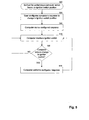
- FIG. 5 is a block flow diagram depicting a method 500 for performing a computer action based on the position of the vehicle's ignition switch 415, in accordance with certain exemplary embodiments.
- the exemplary method 500 is described in terms of the operating system 335 performing user-configured actions in response to the position of the ignition switch 415.
- another application such as an Application Programming Interface (“API") logically coupled to the operating system 335 or a power management utility application, may perform the user-configured actions.
- API Application Programming Interface
- a user configures the operating system 335 of the vehicle mount computer 110 to perform one or more actions or procedures, switch to a mode of operation, execute an application module 336-337, or transmit data to a remote computer 349 based on the position of the ignition switch 415.
- the operating system 335 may be configured to switch to a standby mode, a hibernation mode, or shut down in response to the ignition switch 415 being switched to the off position (or pressed if a momentary switch) while the vehicle mount computer 110 is in an active state.
- the operating system 335 may be configured to prompt the user for what to do in response to the ignition switch 415 being switched to the off position (or pressed if a momentary switch) while the vehicle mount computer 110 is in an active state.
- the operating system 335 may be configured to do nothing start and execute an application module 336-337, or log a current user off of the vehicle mount computer 110, in response to the ignition switch 415 being switched to the off position or pressed while the vehicle mount computer 110 is in an active mode.
- the operating system 335 can be configured to transmit data, such as batch inventory data, to a remote computer 349 in response to the ignition switch 415 being switched to an off position or being pressed while the vehicle 110 is in an active mode.
- the operating system 335 can be configured to transmit data to a remote computer 349 and then switch to an inactive or power saving mode in response to the ignition switch 415 being switched to an off position or being pressed while the vehicle 110 is in an active mode.
- the user can configure the operating system 335 via a control menu.
- the operating system 335 may provide a menu having a list of possible actions to perform or modes of operation to switch to in response to the ignition switch 415 being placed in a certain position or pressed.
- the user can select one or more preferred actions to be performed from the list.
- the vehicle mount computer 110 includes default actions that are performed based on the position of the ignition switch 415 and optionally based on the current state of the vehicle mount computer 110.
- the user 110 can customize the vehicle mount computer 110 to perform desirable actions rather than the default actions.
- the operating system 335 stores the configuration in memory 322.
- the operating system 335 monitors the ignition switch 415.
- the operating system 335 may monitor the power button input or another input logically coupled to the ignition switch 415.
- the operating system 335 conducts an inquiry to determine whether the position of the ignition switch 415.
- the operating system 335 can store the current position of the ignition switch 415 periodically.
- the operating system 415 can compare the current position of the ignition switch 415 to a previously stored position to determine whether the position has changed. If the ignition switch 415 is a pushbutton switch, the operating system 335 can monitor for the ignition switch 415 being pressed.
- the method 500 follows the "YES” branch to block 525. Otherwise, the method 500 follows the "NO” branch to return to block 515 where the operating system 335 continues to monitor the position of the ignition switch 415.
- the operating system 335 causes the vehicle mount computer 110 to perform the configured action based on the position of the ignition switch and optionally the current mode of the vehicle mount computer 110. For example, if the vehicle mount computer system 110 is not in the active mode, then the configured response may be to switch the vehicle mount computer 110 to the active mode in response to the ignition switch 415 being turned on or pressed. In another example, if the vehicle mount computer 110 is in the active mode, then the configured action may be to switch to a power saving mode.
- the method 500 returns to block 515 from block 525 to monitor the position of the ignition switch 415.
- the present invention provides a vehicle mount computer having a configurable behavior controlled by a vehicle's ignition switch.
- a user can configure the computer to perform an action, switch to a different mode, or execute a software application in response to the ignition switch being pressed or the position of the ignition switch being adjusted.
- the computer can be configured to switch to a standby mode, hibernation mode, shutdown, prompt the user to select an action, or do nothing in response to the ignition switch being placed in an off position.
- the ignition switch can be electrically coupled to an input of the computer so that the computer's operating system or another application can monitor the status of the ignition switch.
- the operating system or application can cause the computer to perform the configured response upon detecting a change in the ignition switch's position or an actuation of the ignition switch.
Landscapes
- Engineering & Computer Science (AREA)
- Theoretical Computer Science (AREA)
- General Engineering & Computer Science (AREA)
- Software Systems (AREA)
- Physics & Mathematics (AREA)
- General Physics & Mathematics (AREA)
- Computer Security & Cryptography (AREA)
- Mechanical Engineering (AREA)
- Human Computer Interaction (AREA)
- Health & Medical Sciences (AREA)
- Computing Systems (AREA)
- General Health & Medical Sciences (AREA)
- Medical Informatics (AREA)
- Computer Networks & Wireless Communication (AREA)
- Signal Processing (AREA)
- Power Sources (AREA)
- Management, Administration, Business Operations System, And Electronic Commerce (AREA)
Abstract
Description
- This application claims priority to
U. S. Patent Application No. 12/983,611 filed January 3, 2011 - The invention relates generally to vehicle mounted computer systems, and more particularly to a vehicle mounted computer system having user-configurable behavior controlled by the vehicle's ignition switch.
- Computer terminals are often mounted on vehicles in warehouses, manufacturing facilities, and other workplaces to collect and display data. For example, vehicle mount computers are commonly found on forklift trucks and other utility vehicles. Vehicle mount computers generally include one or more user interfaces, such as a touch screen display and a keyboard or keypad. Many vehicle mount computers also include a wireless radio for communicating with a remote device, such as another computer or server.
- Vehicle mount computers are typically connected to the vehicle's battery to receive supply power. Conventional vehicle mount computers include a power switch or button that an operator can manipulate to turn the vehicle mount computer on and off. Often times, operators leave the vehicle without turning the computer off. For example, an operator may shut down the vehicle at the end of the day, but forget to turn off the vehicle mount computer. This can drain the battery and render the vehicle unusable for the next operator or the next work shift. Furthermore, operators often forget to log out of vehicle mount computers at the conclusion of their work shift. This can allow unauthorized users access to the vehicle mount computer and possibly to a network that the vehicle mount computer is connected to. In addition, the vehicle mount computer's operating system may require an operator to log in again after a certain amount of idle time. This can prevent other operators from logging into the locked computer until an administrator can unlock the computer.
- Some organizations' computer administrators prefer that the computers they are responsible for are placed into a certain state when the computer is not in use. For example, a computer administrator may request that users log off of their computers so that updates to applications and network security can be performed. However, many computer users fail to abide by these preferences causing a nuisance to the administrators.
- The present invention provides methods and systems for controlling a computer by way of a vehicle's ignition switch. The computer can be mounted to or otherwise installed on a vehicle, such as a forklift truck or utility vehicle. The vehicle's ignition switch can be logically coupled as an input to the computer so that the computer can detect or receive an indication of the ignition switch's position. For example, the ignition switch can be electrically coupled to the computer's power button such that the computer's operating system detects ignition switch position changes similar to detecting power button depressions.
- The computer can be configured by a user such as an operator or computer administrator to perform an action, switch to a different mode, log off the current user, execute a software application, or transmit data to another computer or device in response to the ignition switch being pressed or the position of the ignition switch being adjusted. For example, the computer can be configured to switch to a standby mode, switch to a hibernation mode, shutdown, prompt the operator to select an action, execute an application, or do nothing in response to the ignition switch being placed in an off position or being depressed while the computer is in an active mode. The computer also may be configured to switch from a non-active mode to the active mode in response to the ignition switch being turned on or pressed.
- One aspect of the present invention provides a method for performing an action with a vehicle mount computer. A user interface of the vehicle mount computer can receive user input specifying an action for the vehicle mount computer to perform automatically in response to an ignition switch of a vehicle switching from a first position to a second position. The vehicle mount computer can receive an electrical signal indicating that the ignition switch has switched from the first position to the second position. The vehicle mount computer can perform the specified action in response to receiving the electrical signal.
- Another aspect of the present invention provides a computer program product. The computer program product can include a computer-readable medium having computer-readable program code embodied therein for causing a vehicle mount computer to perform an action. The computer-readable medium can include computer-readable program code for receiving, via a user interface of the vehicle mount computer, user input specifying an action for the computer to perform automatically in response to an ignition switch of a vehicle switching from a first position to a second position; computer-readable program code for receiving a signal indicating that the ignition switch has switched from the first position to the second position; and computer-readable program code for causing the specified action to be performed in response to receiving the signal.
- Yet another aspect of the present invention provides a vehicle mountable computer system. The vehicle mountable computer system can include a user interface for receiving a user input specifying an action for the vehicle mount computer system to perform automatically in response to an ignition switch of a vehicle switching from a first position to a second position. An input of the vehicle mountable computer can receive an electrical signal indicating that the ignition switch has switched from the first position to the second position. An application module logically coupled to the input can cause the vehicle mount computer to perform the specified action in response to receiving the electrical signal.
- Yet another aspect of the present invention provides a system that includes a vehicle and a computer mounted thereon. The vehicle can include an ignition switch for selectively activating and deactivating the vehicle. The computer can include a user interface for receiving user input specifying an action for the computer to perform automatically in response to the ignition switch being switched to a certain position. The computer also can include an input electrically coupled to the ignition switch to receive an electrical signal indicating that the ignition switch has switched to the certain position. An application module of the computer can cause the computer to perform the specified action in response to receiving the electrical signal.
- These and other aspects, features, and embodiments of the invention will become apparent to a person of ordinary skill in the art upon consideration of the following detailed description of illustrated embodiments exemplifying the best mode for carrying out the invention as presently perceived.
- For a more complete understanding of the exemplary embodiments of the present invention and the advantages thereof, reference is now made to the following description in conjunction with the accompanying drawings in which:
-
Figure 1 depicts an operating environment for a vehicle mount computer, in accordance with certain exemplary embodiments; -
Figure 2 is a front view of the vehicle mount computer ofFigure 1 , in accordance with certain exemplary embodiments; -
Figure 3 is a block diagram depicting components of the vehicle mount computer ofFigure 1 , in accordance with certain exemplary embodiments; -
Figure 4 is a block schematic diagram depicting electrical connections between the vehicle mount computer ofFigure 1 and an ignition switch, in accordance with certain exemplary embodiments; and -
Figure 5 is a block flow diagram depicting a method for performing a computer action based on the position of a vehicle's ignition switch, in accordance with certain exemplary embodiments. - The drawings illustrate only exemplary embodiments of the invention and are therefore not to be considered limiting of its scope, as the invention may admit to other equally effective embodiments. The elements and features shown in the drawings are not necessarily to scale, emphasis instead being placed upon clearly illustrating the principles of exemplary embodiments of the present invention. Additionally, certain dimensions may be exaggerated to help visually convey such principles.
- Referring now to the figures, in which like numerals represent like (but not necessarily identical) elements throughout the figures, exemplary embodiments of the present invention are described in detail.
Figure 1 depicts anoperating environment 100 for avehicle mount computer 110, in accordance with certain exemplary embodiments. Referring toFigure 1 , theoperating environment 100 includes avehicle 105 with thevehicle mount computer 110 mounted thereon. Although theexemplary vehicle 105 is illustrated as a forklift truck, thevehicle mount computer 110 can be mounted to or installed on other types of vehicle, such as a utility truck or cart. Thevehicle 105 includes an ignition switch 415 (Figure 4 ) for activating and deactivating thevehicle 105. As described in further detail below, theignition switch 415 can be logically coupled to thevehicle mount computer 110. Thevehicle mount computer 110 can be configured to switch from one mode to another or perform certain actions, tasks, or operations in response to theignition switch 415 being switched from one position to another (rotary switch) or being pressed (pushbutton switch). -
Vehicle mount computers 110 are often used in warehouses, manufacturing facilities, and shop floors to collect and display data. For example, vehicle mountcomputers 110 are commonly used in warehouses to track inventory of products being received and shipped. Thevehicle mount computer 110 can be coupled to peripheral devices, such as a bar code scanner, to collect data. As described in further detail below, thevehicle mount computer 110 also can include one or more wireless radios for communicating with another computer or device. An operator can interact with thevehicle mount computer 110 while seated in thevehicle 105. Thecomputer 110 can be mounted in a stationary position inside thevehicle 105 or on a positionable object, such as a swing arm. -
Figure 2 is a front view of thevehicle mount computer 110 ofFigure 1 , in accordance with certain exemplary embodiments. Referring toFigure 2 , thevehicle mount computer 110 includes several user interfaces. In particular, the exemplaryvehicle mount computer 110 includes adisplay device 205, a keyboard orkeypad 210, and userconfigurable keys 215. In certain exemplary embodiments, thedisplay device 205 includes a touch sensitive screen 360 (Figure 3 ). An operator can use thekeypad 210, userconfigurable keys 215, and touchsensitive screen 360 to enter commands and data to thevehicle mount computer 110. Thevehicle mount computer 110 also includes apower button 225. An operator can selectively turn thevehicle mount computer 110 on and off by pressing thepower button 225. Although not shown, thevehicle mount computer 110 also can include a mouse or other pointing device. -
Figure 3 is a block diagram depicting components of thevehicle mount computer 110 ofFigure 1 , in accordance with certain exemplary embodiments. Referring toFigure 3 , thevehicle mount computer 110 includes aprocessing unit 321, asystem memory 322, and a system bus 323 that couples various system components, including thesystem memory 322, to theprocessing unit 321. The system bus 323 can include any of several types of bus structures, including a memory bus or memory controller, a peripheral bus, or a local bus, using any of a variety of bus architectures. Thesystem memory 322 includes a read-only memory ("ROM") 324 and a random access memory ("RAM") 325. A basic input/output system ("BIOS") 326 containing the basic routines that help to transfer information between elements within thevehicle mount computer 110, such as during start-up, is stored in theROM 324. - The
vehicle mount computer 110 also includes ahard disk drive 327 for reading from and writing to a hard disk (not shown) and anoptical disk drive 328 for reading from or writing to a removableoptical disk 329 such as a CD-ROM, compact disk - read/write ("CD/RW"), DVD, or other optical media. Thehard disk drive 327 andoptical disk drive 328 are connected to the system bus 323 by a harddisk drive interface 332 and an opticaldisk drive interface 333, respectively. Although the exemplaryvehicle mount computer 110 employs aROM 324, aRAM 325, ahard disk drive 327, and a removableoptical disk 329, it should be appreciated by a person of ordinary skill in the art having the benefit of the present disclosure that other types of computer readable media also can be used in the exemplaryvehicle mount computer 110. For example, the computer readable media can include any apparatus that can contain, store, communicate, propagate, or transport data for use by or in connection with one or more components of thevehicle mount computer 110, including any electronic, magnetic, optical, electromagnetic, infrared, or semiconductor system (or apparatus or device) or propagation medium, such as magnetic cassettes, flash memory cards, digital video disks, Bernoulli cartridges, and the like. The drives and their associated computer readable media can provide nonvolatile storage of computer-executable instructions, data structures, program modules, and other data for thevehicle mount computer 110. - A number of modules can be stored on the
ROM 324,RAM 325,hard disk drive 327 oroptical disk 329, including anoperating system 335 and various application modules 336-337. Application modules 336-337 can include routines, sub-routines, programs, objects, components, data structures, etc., which perform particular tasks or implement particular abstract data types. For example, theapplication module 336 may be an inventory application for use in collecting and displaying inventory information in a warehouse. - As described in further detail below, the
operating system 335 or another application module can be configured by a user to perform certain actions or tasks when thepower button 225 is pressed. For example, theoperating system 335 can be configured to cause thevehicle mount computer 110 to stand by, hibernate, shut down, do nothing, prompt the operator for what action to perform, start an application module 336-337, or to transmit data (e.g., in a batch) to another computer or device when thepower button 225 is pressed and thevehicle mount computer 110 is turned on. The standby mode is a power saving mode where most or all components of thevehicle mount computer 110 switches to a low-power state. The hibernate mode includes storing an image of the vehicle mount computer's current state and shutting almost completely off. Thevehicle mount computer 110 can use the stored image to return to that state when returning from the hibernate mode. If configured to prompt the operator for what action to perform, theoperating system 335 can present a dialog box including the possible actions for the operator to select from. In certain exemplary embodiments, theoperating system 335 is Advanced Configuration and Power Interface ("ACPI") compliant, such as MICROSOFT WINDOWS XP. - The
operating system 335 is logically coupled to thepower button 225, for example via the system bus 323, to receive a signal indicating whether thepower button 225 is pressed. In response to receiving this indication signal, theoperating system 335 performs the user-configured action. In certain exemplary embodiments, theoperating system 335 includes default settings for responding to thepower button 335 being pressed. The user can retain the default settings or adjust the default settings as described below. - An operator can enter commands and information to the
vehicle mount computer 110 through the input devices, such as thekeypad 210 and the userconfigurable keys 215. These and other input devices are often connected to theprocessing unit 321 through aserial port interface 346 that is coupled to the system bus 323, but can be connected by other interfaces, such as a parallel port, game port, or the like. - The
display 205 also can be connected to the system bus 323 via an interface, such as avideo adapter 348, to receive content for display by thedisplay 205. Theexemplary display 205 incorporates a touchsensitive screen 360 coupled to theprocessing unit 321 by way of atouch screen controller 361. For example, the touchsensitive screen 360 can include resistive, capacitive, surface acoustic wave ("SAW'), infrared ("IR"), strain gauge, dispersive signal technology, acoustic pulse recognition, and optical touch sensing technology, as would be readily understood by a person of ordinary skill in the art having the benefit of the present disclosure. Thetouch screen controller 361 can determine the location of a user's touch (e.g., with a finger, stylus, pen, or other object) on or near the touchsensitive screen 360. In addition to thedisplay 205, thevehicle mount computer 110 can include other peripheral output devices, such as speakers (not shown). - The
vehicle mount computer 110 is configured to operate in a networked environment using logical connections to one or moreremote computers 349. Theremote computer 349 can be any network device, such as a personal computer, a server, a client, a router, a network PC, a peer device, or other device. While theremote computer 349 typically includes many or all of the elements described above relative to thevehicle mount computer 110, only amemory storage device 350 has been illustrated inFigure 3 for simplicity. The logical connection depicted inFigure 3 includes a wireless LAN ("WLAN") 304 that thevehicle mount computer 110 communicates with via an antenna (not shown). In a networked environment, program modules depicted relative to thevehicle mount computer 110, or portions thereof, can be stored in the remotememory storage device 350. - It will be appreciated that the network connection shown in
Figure 3 is exemplary and other means of establishing a communications link between the computers can be used. For example, thevehicle mount computer 110 can communicate via Bluetooth, Zigbee, induction wireless, or any other suitable wireless or wired technology. Moreover, those skilled in the art will appreciate that thevehicle mount computer 110 illustrated inFigure 3 can have any of several other suitable computer system configurations. For example, thevehicle mount computer 110 may not include certain components, in alternative exemplary embodiments. - As briefly discussed above, an operator or other user can configure the operating system 335 (or another program module 336-337) to switch modes or perform one or more actions in response to the
power button 225 being pressed. Thevehicle mount computer 110 also can be configured such that theoperating system 335 performs the one or more actions in response to the vehicle'signition switch 415 being switched from one position to another or being pressed. In such a configuration, a user can configure theoperating system 335 to cause thevehicle mount computer 110 to standby, hibernate, shut down, do nothing, log off the current user, prompt the user for what action to perform, start and/or execute an application module 336-337, or to transmit data to aremote computer 349 in response to theignition switch 415 being switched from one position to another or being pressed. - The
operating system 335 can be configured to perform one or more of the actions based on the ignition switch position and the current state or mode of thevehicle mount computer 110. For example, a user can configure theoperating system 335 to switch thevehicle mount computer 110 to a power saving mode (e.g., standby, hibernate, or shutdown) in response to theignition switch 415 being switched to an off position or being pressed while thevehicle mount computer 110 is in an active mode. In another example, a user can configure theoperating system 335 to switch thevehicle mount computer 110 to the active mode in response to theignition switch 415 being placed in an on position or being pressed while thevehicle mount computer 110 is in an inactive mode. In yet another example, theoperating system 335 can be configured to prompt the user for what action to perform or execute and application in response to theignition switch 415 being switched to an on position or being pressed while thevehicle mount computer 110 is in the active mode. In yet another example, theoperating system 335 can be configured to transmit data, such as batch inventory data, to aremote computer 349 in response to theignition switch 415 being switched to an off position or being pressed while thevehicle 110 is in an active mode. In yet another example, theoperating system 335 can be configured to transmit data to aremote computer 349 and then switch to an inactive or power saving mode in response to theignition switch 415 being switched to an off position or being pressed while thevehicle 110 is in an active mode. - This unique ignition switch configurable behavior enables users or computer administrators to place the
vehicle mount computer 110 into a preferred state when thevehicle 105 is turned off. For example, theoperating system 335 may cause thevehicle mount computer 110 to switch to a power saving mode (e.g., hibernate, standby, or shutdown) when thevehicle 105 is turned off. Or, theoperating system 335 may log off the current user so that another user can log in to thevehicle mount computer 110. This ignition switch control can obviate the need for a user to consciously place thevehicle mount computer 110 into the preferred state, for example at the end of a work shift. -
Figure 4 is a block schematic diagram depicting electrical connections between thevehicle mount computer 110 ofFigure 1 and theignition switch 415 of thevehicle 105, in accordance with certain exemplary embodiments. Referring toFigure 4 , thevehicle mount computer 110 includes apower supply 455 that provides regulated supply power to the computer's components, such as those illustrated inFigure 3 and discussed above. For example, thepower supply 455 may provide a steady 12 VDC supply to the computer's components. - The
vehicle 105 includes abattery 413 that provides power to thevehicle 105 and to thevehicle mount computer 110. Thebattery 413 is electrically coupled to the computer'spower supply 455 via apower supply 420, an on/offswitch 435, adiode 471, and one or more electrical conductors. In certain exemplary embodiments, thepower supply 420 is a DC-DC isolated power supply that converts the voltage level of the battery to a voltage level suitable for thepower supply 455. For example, thepower supply 420 may convert a 10 VDC - 100 VDC supply provided by thebattery 413 to 13.2 VDC for thepower supply 455. - An operator can selectively apply or remove power from the
vehicle mount computer 110 using the on/offswitch 435. The on/offswitch 435 can be mounted on thevehicle 105 and is typically mounted proximal to thevehicle mount computer 110. For example, the on/offswitch 435 may be mounted on a docking or mountingassembly 430 that also supports thevehicle mount computer 110. In alternative exemplary embodiments, the on/offswitch 435 is mounted near the vehicle'signition switch 415. - The
vehicle mount computer 110 also includes abackup battery 465 connected to the computer'spower supply 455 via adiode 473 and one or more electrical conductors. Thebackup battery 465 can provide power to thepower supply 465 when external power is not available. For example, if the vehicle'sbattery 413 is drained, thebackup battery 465 may power thevehicle mount computer 110. - The
ignition switch 415 is used to activate and deactivate thevehicle 105. In certain exemplary embodiments, theignition switch 415 includes a first "on" position for activating thevehicle 105 and a second "off' position for deactivating thevehicle 105. An operator can activate thevehicle 105 by inserting a key into theignition switch 413 and placing theignition switch 415 in the on position. To deactivate thevehicle 105, the operator can place theignition switch 415 in the off position. In certain exemplary embodiments, theignition switch 415 may include additional positions, such as a "start" position for gas powered vehicles and an "accessory" position. The operating system 335 (or other application module 336-337) can be configured by a user to perform an action based on each position and optionally the current mode or state of thevehicle mount computer 110. - In certain alternative exemplary embodiments, the
switch 415 can be embodied as another type of switch, such as a pushbutton switch, a slider switch, or a rotary switch to name a few. If theswitch 415 is a pushbutton switch or other type of momentary switch, thevehicle 105 may be started and stopped in response to theswitch 415 being pressed. - In the illustrated embodiment, the
ignition switch 415 is electrically coupled in series with thepower button 475 between thebattery 413 and thepower button input 225 of thevehicle mount computer 110. In such a configuration, theignition switch 415 can control thepower button input 225 to theoperating system 335. That is, theoperating system 335 can detect the position of theignition switch 415 similar to detecting inputs from thepower button 475. Accordingly, theoperating system 335 responds to the position of theignition switch 415 based on the user configuration. In certain alternative embodiments, theignition switch 415 is electrically coupled to another input of thevehicle mount computer 110 rather than thepower button input 225. - In certain alternative embodiments, the
ignition switch 415 is electrically coupled to thepower button input 225 in parallel with thepower button 475. In such embodiments, an operator can use theignition switch 415 or thepower button 475 to control thevehicle mount computer 110. - In either implementation, the
operating system 335 can detect the position or status of theignition switch 415 and, in response, cause thevehicle mount computer 110 to perform an action, switch between modes of operation, execute an application, do nothing, log off the current user, or prompt the user to select an action. The action performed by theoperating system 335 can be configured by a user and also can depend on the current mode or state of thevehicle mount computer 110. For example, if theignition switch 415 is turned to the on position while thevehicle mount computer 110 is turned off, theoperating system 335 can detect the ignition switch's position and cause thevehicle mount computer 110 to turn on. In another example, if thevehicle mount computer 110 is in an active mode and theignition switch 415 is moved to the off position, theoperating system 335 can cause thevehicle mount computer 110 to perform an action or switch to a certain mode of operation, such as the standby mode or hibernation mode. - As shown in
Figure 4 , thepower button 475 and thepower button input 225 are electrically coupled in series to the negative terminal (ground) of thebattery 413. In alternative embodiments, thepower button 475 and thepower button input 225 can be electrically coupled in series to the positive terminal of thebattery 413, for example in parallel with an ignition input to thecomputer terminal 110 that is coupled to theoperating system 335. In this manner, the negative terminal of thebattery 413 can always be connected to thevehicle mount computer 110 without a switch. Thepower button 475 and the ignition input can have "always on" logic (if thepower supply 420 and the on/offswitch 435 are on) that can initiate the configured response of thevehicle mount computer 110 either by thepower button 475 or theignition switch 415. -
Figure 5 is a block flow diagram depicting amethod 500 for performing a computer action based on the position of the vehicle'signition switch 415, in accordance with certain exemplary embodiments. Theexemplary method 500 is described in terms of theoperating system 335 performing user-configured actions in response to the position of theignition switch 415. However, another application, such as an Application Programming Interface ("API") logically coupled to theoperating system 335 or a power management utility application, may perform the user-configured actions. - Referring to
Figures 1 ,4 , and5 , inblock 505, a user configures theoperating system 335 of thevehicle mount computer 110 to perform one or more actions or procedures, switch to a mode of operation, execute an application module 336-337, or transmit data to aremote computer 349 based on the position of theignition switch 415. For example, theoperating system 335 may be configured to switch to a standby mode, a hibernation mode, or shut down in response to theignition switch 415 being switched to the off position (or pressed if a momentary switch) while thevehicle mount computer 110 is in an active state. In another example, theoperating system 335 may be configured to prompt the user for what to do in response to theignition switch 415 being switched to the off position (or pressed if a momentary switch) while thevehicle mount computer 110 is in an active state. In yet another example, theoperating system 335 may be configured to do nothing start and execute an application module 336-337, or log a current user off of thevehicle mount computer 110, in response to theignition switch 415 being switched to the off position or pressed while thevehicle mount computer 110 is in an active mode. In yet another example, theoperating system 335 can be configured to transmit data, such as batch inventory data, to aremote computer 349 in response to theignition switch 415 being switched to an off position or being pressed while thevehicle 110 is in an active mode. In yet another example, theoperating system 335 can be configured to transmit data to aremote computer 349 and then switch to an inactive or power saving mode in response to theignition switch 415 being switched to an off position or being pressed while thevehicle 110 is in an active mode. - In certain exemplary embodiments, the user can configure the
operating system 335 via a control menu. For example, theoperating system 335 may provide a menu having a list of possible actions to perform or modes of operation to switch to in response to theignition switch 415 being placed in a certain position or pressed. The user can select one or more preferred actions to be performed from the list. In certain exemplary embodiments, thevehicle mount computer 110 includes default actions that are performed based on the position of theignition switch 415 and optionally based on the current state of thevehicle mount computer 110. Theuser 110 can customize thevehicle mount computer 110 to perform desirable actions rather than the default actions. - In
block 510, theoperating system 335 stores the configuration inmemory 322. Inblock 515, theoperating system 335 monitors theignition switch 415. For example, theoperating system 335 may monitor the power button input or another input logically coupled to theignition switch 415. Inblock 520, theoperating system 335 conducts an inquiry to determine whether the position of theignition switch 415. For example, theoperating system 335 can store the current position of theignition switch 415 periodically. Theoperating system 415 can compare the current position of theignition switch 415 to a previously stored position to determine whether the position has changed. If theignition switch 415 is a pushbutton switch, theoperating system 335 can monitor for theignition switch 415 being pressed. If theoperating system 335 determines that the position of theignition switch 415 has changed (or has been pressed), then themethod 500 follows the "YES" branch to block 525. Otherwise, themethod 500 follows the "NO" branch to return to block 515 where theoperating system 335 continues to monitor the position of theignition switch 415. - In
block 520, theoperating system 335 causes thevehicle mount computer 110 to perform the configured action based on the position of the ignition switch and optionally the current mode of thevehicle mount computer 110. For example, if the vehiclemount computer system 110 is not in the active mode, then the configured response may be to switch thevehicle mount computer 110 to the active mode in response to theignition switch 415 being turned on or pressed. In another example, if thevehicle mount computer 110 is in the active mode, then the configured action may be to switch to a power saving mode. Themethod 500 returns to block 515 fromblock 525 to monitor the position of theignition switch 415. - Among the apparatus and methods set forth herein there is set forth herein:
- A1. A method for performing an action with a vehicle mount computer, comprising:
- receiving, at a user interface of the vehicle mount computer, user input specifying an action for the vehicle mount computer to perform automatically in response to an ignition switch of a vehicle switching from a first position to a second position; and
- receiving, with the vehicle mount computer, an electrical signal indicating that the ignition switch has switched from the first position to the second position,
- wherein the vehicle mount computer performs the specified action in response to receiving the electrical signal.
- A2. The method of A1, wherein the vehicle mount computer receives the electrical signal through a port that is electrically connected to the ignition switch via an electrical circuit.
- A3. The method of A1, further comprising storing information in nonvolatile memory of the vehicle mount computer in response to receiving the user input, wherein the stored information configures the vehicle mount computer to perform the specified action in response to receiving the electrical signal.
- A4. The method of A1, wherein the specified action comprises substantially changing power consumption of the vehicle mount computer.
- A5. The method of A1, wherein the first position comprises a position for activating the vehicle and the second position comprises a position for deactivating the vehicle, and wherein the specified action comprises one of switching the vehicle mount computer to a standby mode, switching the vehicle mount computer to a hibernation mode, and removing power from one or more components of the vehicle mount computer.
- A6. The method of A1, wherein the first position comprises a position for activating the vehicle and the second position comprises a position for deactivating the vehicle, and wherein the specified action comprises one of prompting a user to select from a plurality of actions and executing an application.
- A7. The method of A1, wherein the first position comprises a position for deactivating the vehicle and the second position comprises a position for activating the vehicle, and wherein the selected action comprises switching the vehicle mount computer to an active mode.
- A8. The method of A1, wherein the specified action is based on a current mode for the vehicle mount computer.
-
B 1. A computer program product, comprising:- a computer-readable medium having computer-readable program code embodied therein for causing a vehicle mount computer to perform an action, the computer-readable medium comprising:
- computer-readable program code for receiving, via a user interface of the vehicle mount computer, user input specifying an action for the computer to perform automatically in response to an ignition switch of a vehicle switching from a first position to a second position;
- computer-readable program code for receiving a signal indicating that the ignition switch has switched from the first position to the second position; and
- computer-readable program code for causing the specified action to be performed in response to receiving the signal.
- a computer-readable medium having computer-readable program code embodied therein for causing a vehicle mount computer to perform an action, the computer-readable medium comprising:
- B2. The computer program product of B1, wherein the signal is received through a port of the vehicle mount computer that is electrically connected to the ignition switch via an electrical circuit.
- B3. The computer program product of B1, further comprising computer-readable program code for storing information in nonvolatile memory of the vehicle mount computer in response to receiving the user input, wherein the stored information configures the vehicle mount computer to perform the specified action in response to receiving the signal.
- B4. The computer program product of B1, wherein the specified action comprise substantially changing power consumption of the vehicle mount computer.
- B5. The computer program product of B1, wherein the first position comprises a position for activating the vehicle and the second position comprises a position for deactivating the vehicle, and wherein the specified action comprises one of switching the vehicle mount computer to a standby mode, switching the vehicle computer to a hibernation mode, and removing power from one or more components of the vehicle mount computer.
- B6. The computer program product of B1, wherein the first position comprises a position for activating the vehicle and the second position comprises a position for deactivating the vehicle, and wherein the specified action comprises one of prompting a user to select from a plurality of actions and executing an application.
- B7. The computer program product of B1, wherein the first position comprises a position for deactivating the vehicle and the second position comprises a position for activating the vehicle, and wherein the selected action comprises switching the vehicle mount computer to an active mode.
- B8. The computer program product of B1, wherein the specified action is based on a current mode for the vehicle mount computer.
- C1. A vehicle mountable computer system, comprising:
- a user interface for receiving a user input specifying an action for the vehicle mount computer system to perform automatically in response to an ignition switch of a vehicle switching from a first position to a second position;
- an input for receiving an electrical signal indicating that the ignition switch has switched from the first position to the second position; and
- an application module logically coupled to the input for causing the vehicle mount computer to perform the specified action in response to receiving the electrical signal.
- C2. The vehicle mountable computer system of C1, wherein the application module comprises an operating system.
- C3. The vehicle mountable computer system of C1, further comprising a second application module for storing information in nonvolatile memory of the vehicle mount computer in response to receiving the user input, wherein the stored information configures the application module to perform the specified action in response to receiving the electrical signal.
- C4. The vehicle mountable computer system of C1, wherein the input comprises a port that is electrically coupled to the ignition switch via an electrical circuit.
- C5. The vehicle mountable computer system of C1, wherein the specified action comprises substantially changing power consumption of the vehicle mount computer system.
- C6. The vehicle mountable computer system of C1, wherein the selected action is based on a current mode for the computer.
- D1. A system, comprising:
- a vehicle comprising an ignition switch for selectively activating and deactivating the vehicle; and
- a computer mounted on the vehicle and comprising:
- a user interface for receiving user input specifying an action for the computer to perform automatically in response to the ignition switch being switched to a certain position;
- an input electrically coupled to the ignition switch to receive an electrical signal indicating that the ignition switch has switched to the certain position;
- an application module logically coupled to the input for causing the computer to perform the specified action in response to receiving the electrical signal.
- D2. The system of D1, wherein the computer further comprises a second application module for storing information in nonvolatile memory of the computer in response to receiving the user input, wherein the stored information configures the application module to perform the specified action in response to receiving the electrical signal.
- D3. The system of D1, wherein the input comprises a port that is electrically coupled to the ignition switch via an electrical circuit.
- D4. The system of D1, wherein the specified action comprises substantially changing power consumption of the computer.
- D5. The system of D1, wherein the vehicle comprises a lift truck.
- One of ordinary skill in the art would appreciate that the present invention provides a vehicle mount computer having a configurable behavior controlled by a vehicle's ignition switch. A user can configure the computer to perform an action, switch to a different mode, or execute a software application in response to the ignition switch being pressed or the position of the ignition switch being adjusted. For example, the computer can be configured to switch to a standby mode, hibernation mode, shutdown, prompt the user to select an action, or do nothing in response to the ignition switch being placed in an off position. The ignition switch can be electrically coupled to an input of the computer so that the computer's operating system or another application can monitor the status of the ignition switch. The operating system or application can cause the computer to perform the configured response upon detecting a change in the ignition switch's position or an actuation of the ignition switch.
- Although specific embodiments have been described above in detail, the description is merely for purposes of illustration. It should be appreciated, therefore, that many aspects of the invention were described above by way of example only and are not intended as required or essential elements of the invention unless explicitly stated otherwise. Various modifications of, and equivalent steps corresponding to, the disclosed aspects of the exemplary embodiments, in addition to those described above, can be made by a person of ordinary skill in the art, having the benefit of this disclosure, without departing from the spirit and scope of the invention defined in the following claims, the scope of which is to be accorded the broadest interpretation so as to encompass such modifications and equivalent structures.
Claims (15)
- A method for performing an action with a vehicle mount computer, comprising:receiving, at a user interface of the vehicle mount computer, user input specifying an action for the vehicle mount computer to perform automatically in response to an ignition switch of a vehicle switching from a first position to a second position; andreceiving, with the vehicle mount computer, an electrical signal indicating that the ignition switch has switched from the first position to the second position,wherein the vehicle mount computer performs the specified action in response to receiving the electrical signal.
- The method of Claim 1, wherein the vehicle mount computer receives the electrical signal through a port that is electrically connected to the ignition switch via an electrical circuit.
- The method of Claim 1, further comprising storing information in nonvolatile memory of the vehicle mount computer in response to receiving the user input, wherein the stored information configures the vehicle mount computer to perform the specified action in response to receiving the electrical signal.
- The method of Claim 1, wherein the specified action comprises substantially changing power consumption of the vehicle mount computer.
- The method of Claim 1, wherein the first position comprises a position for activating the vehicle and the second position comprises a position for deactivating the vehicle, and wherein the specified action comprises one of switching the vehicle mount computer to a standby mode, switching the vehicle mount computer to a hibernation mode, and removing power from one or more components of the vehicle mount computer.
- The method of Claim 1, wherein the first position comprises a position for activating the vehicle and the second position comprises a position for deactivating the vehicle, and wherein the specified action comprises one of prompting a user to select from a plurality of actions and executing an application.
- The method of Claim 1, wherein the specified action is based on a current mode for the vehicle mount computer.
- A computer program product, comprising:a computer-readable medium having computer-readable program code embodied therein for causing a vehicle mount computer to perform an action, the computer-readable medium comprising:computer-readable program code for receiving, via a user interface of the vehicle mount computer, user input specifying an action for the computer to perform automatically in response to an ignition switch of a vehicle switching from a first position to a second position;computer-readable program code for receiving a signal indicating that the ignition switch has switched from the first position to the second position; andcomputer-readable program code for causing the specified action to be performed in response to receiving the signal.
- The computer program product of Claim 8, wherein the signal is received through a port of the vehicle mount computer that is electrically connected to the ignition switch via an electrical circuit.
- The computer program product of Claim 8, further comprising computer-readable program code for storing information in nonvolatile memory of the vehicle mount computer in response to receiving the user input, wherein the stored information configures the vehicle mount computer to perform the specified action in response to receiving the signal.
- The computer program product of Claim 8, wherein the specified action comprise substantially changing power consumption of the vehicle mount computer.
- The computer program product of Claim 8, wherein the first position comprises a position for activating the vehicle and the second position comprises a position for deactivating the vehicle, and wherein the specified action comprises one of switching the vehicle mount computer to a standby mode, switching the vehicle computer to a hibernation mode, and removing power from one or more components of the vehicle mount computer.
- The computer program product of Claim 8, wherein the first position comprises a position for activating the vehicle and the second position comprises a position for deactivating the vehicle, and wherein the specified action comprises one of prompting a user to select from a plurality of actions and executing an application.
- The computer program product of Claim 8, wherein the first position comprises a position for deactivating the vehicle and the second position comprises a position for activating the vehicle, and wherein the selected action comprises switching the vehicle mount computer to an active mode.
- The computer program product of Claim 8, wherein the specified action is based on a current mode for the vehicle mount computer.
Applications Claiming Priority (1)
| Application Number | Priority Date | Filing Date | Title |
|---|---|---|---|
| US12/983,611 US8996194B2 (en) | 2011-01-03 | 2011-01-03 | Vehicle mount computer with configurable ignition switch behavior |
Publications (1)
| Publication Number | Publication Date |
|---|---|
| EP2485116A1 true EP2485116A1 (en) | 2012-08-08 |
Family
ID=46381466
Family Applications (1)
| Application Number | Title | Priority Date | Filing Date |
|---|---|---|---|
| EP11196084A Ceased EP2485116A1 (en) | 2011-01-03 | 2011-12-29 | Vehicle mount computer with configurable ignition switch behavior |
Country Status (3)
| Country | Link |
|---|---|
| US (3) | US8996194B2 (en) |
| EP (1) | EP2485116A1 (en) |
| CN (2) | CN107422833B (en) |
Cited By (1)
| Publication number | Priority date | Publication date | Assignee | Title |
|---|---|---|---|---|
| US9448610B2 (en) | 2011-01-03 | 2016-09-20 | Ems Technologies, Inc. | Vehicle mount computer with configurable ignition switch behavior |
Families Citing this family (333)
| Publication number | Priority date | Publication date | Assignee | Title |
|---|---|---|---|---|
| US8908995B2 (en) | 2009-01-12 | 2014-12-09 | Intermec Ip Corp. | Semi-automatic dimensioning with imager on a portable device |
| US8914290B2 (en) | 2011-05-20 | 2014-12-16 | Vocollect, Inc. | Systems and methods for dynamically improving user intelligibility of synthesized speech in a work environment |
| US8977879B2 (en) * | 2012-03-30 | 2015-03-10 | Motorola Solutions, Inc. | Method and apparatus for enhancing a multi-stage hibernate and resume process |
| US9779546B2 (en) | 2012-05-04 | 2017-10-03 | Intermec Ip Corp. | Volume dimensioning systems and methods |
| US9007368B2 (en) | 2012-05-07 | 2015-04-14 | Intermec Ip Corp. | Dimensioning system calibration systems and methods |
| US10007858B2 (en) | 2012-05-15 | 2018-06-26 | Honeywell International Inc. | Terminals and methods for dimensioning objects |
| EP2864929A4 (en) | 2012-06-20 | 2016-03-30 | Metrologic Instr Inc | Laser scanning code symbol reading system providing control over length of laser scan line projected onto a scanned object using dynamic range-dependent scan angle control |
| US10321127B2 (en) | 2012-08-20 | 2019-06-11 | Intermec Ip Corp. | Volume dimensioning system calibration systems and methods |
| DE102012108485B4 (en) * | 2012-09-11 | 2024-09-26 | Dr. Ing. H.C. F. Porsche Aktiengesellschaft | Method for operating a hybrid vehicle |
| US20140104413A1 (en) | 2012-10-16 | 2014-04-17 | Hand Held Products, Inc. | Integrated dimensioning and weighing system |
| CN103780847A (en) | 2012-10-24 | 2014-05-07 | 霍尼韦尔国际公司 | Chip on board-based highly-integrated imager |
| WO2014110495A2 (en) | 2013-01-11 | 2014-07-17 | Hand Held Products, Inc. | System, method, and computer-readable medium for managing edge devices |
| US9080856B2 (en) | 2013-03-13 | 2015-07-14 | Intermec Ip Corp. | Systems and methods for enhancing dimensioning, for example volume dimensioning |
| US9780749B2 (en) * | 2013-03-20 | 2017-10-03 | Ford Global Technologies, Llc | Radio mute strategy for non-can radios used with smart starting systems |
| US9037344B2 (en) | 2013-05-24 | 2015-05-19 | Hand Held Products, Inc. | System and method for display of information using a vehicle-mount computer |
| US9930142B2 (en) | 2013-05-24 | 2018-03-27 | Hand Held Products, Inc. | System for providing a continuous communication link with a symbol reading device |
| US8918250B2 (en) | 2013-05-24 | 2014-12-23 | Hand Held Products, Inc. | System and method for display of information using a vehicle-mount computer |
| US10228452B2 (en) | 2013-06-07 | 2019-03-12 | Hand Held Products, Inc. | Method of error correction for 3D imaging device |
| US9104929B2 (en) | 2013-06-26 | 2015-08-11 | Hand Held Products, Inc. | Code symbol reading system having adaptive autofocus |
| US8985461B2 (en) | 2013-06-28 | 2015-03-24 | Hand Held Products, Inc. | Mobile device having an improved user interface for reading code symbols |
| JP6335063B2 (en) * | 2013-08-05 | 2018-05-30 | ハーマン インターナショナル インダストリーズ インコーポレイテッド | System and method for in-vehicle computing system |
| US9672398B2 (en) | 2013-08-26 | 2017-06-06 | Intermec Ip Corporation | Aiming imagers |
| US9572901B2 (en) | 2013-09-06 | 2017-02-21 | Hand Held Products, Inc. | Device having light source to reduce surface pathogens |
| US8870074B1 (en) | 2013-09-11 | 2014-10-28 | Hand Held Products, Inc | Handheld indicia reader having locking endcap |
| US9134780B2 (en) * | 2013-11-11 | 2015-09-15 | Symbol Technologies, Llc | Apparatus and method for providing adaptive power state control based on ignition input |
| US9373018B2 (en) | 2014-01-08 | 2016-06-21 | Hand Held Products, Inc. | Indicia-reader having unitary-construction |
| US10139495B2 (en) | 2014-01-24 | 2018-11-27 | Hand Held Products, Inc. | Shelving and package locating systems for delivery vehicles |
| US9665757B2 (en) | 2014-03-07 | 2017-05-30 | Hand Held Products, Inc. | Indicia reader for size-limited applications |
| US9412242B2 (en) | 2014-04-04 | 2016-08-09 | Hand Held Products, Inc. | Multifunction point of sale system |
| US9258033B2 (en) | 2014-04-21 | 2016-02-09 | Hand Held Products, Inc. | Docking system and method using near field communication |
| US9224022B2 (en) | 2014-04-29 | 2015-12-29 | Hand Held Products, Inc. | Autofocus lens system for indicia readers |
| US9478113B2 (en) | 2014-06-27 | 2016-10-25 | Hand Held Products, Inc. | Cordless indicia reader with a multifunction coil for wireless charging and EAS deactivation |
| DE102014213922B4 (en) * | 2014-07-17 | 2020-02-20 | Continental Automotive Gmbh | Vehicle infotainment system |
| US9823059B2 (en) | 2014-08-06 | 2017-11-21 | Hand Held Products, Inc. | Dimensioning system with guided alignment |
| US20160062473A1 (en) | 2014-08-29 | 2016-03-03 | Hand Held Products, Inc. | Gesture-controlled computer system |
| US10810530B2 (en) | 2014-09-26 | 2020-10-20 | Hand Held Products, Inc. | System and method for workflow management |
| EP3001368A1 (en) | 2014-09-26 | 2016-03-30 | Honeywell International Inc. | System and method for workflow management |
| US10810715B2 (en) | 2014-10-10 | 2020-10-20 | Hand Held Products, Inc | System and method for picking validation |
| US9779276B2 (en) | 2014-10-10 | 2017-10-03 | Hand Held Products, Inc. | Depth sensor based auto-focus system for an indicia scanner |
| US10775165B2 (en) | 2014-10-10 | 2020-09-15 | Hand Held Products, Inc. | Methods for improving the accuracy of dimensioning-system measurements |
| US9443222B2 (en) | 2014-10-14 | 2016-09-13 | Hand Held Products, Inc. | Identifying inventory items in a storage facility |
| US10909490B2 (en) | 2014-10-15 | 2021-02-02 | Vocollect, Inc. | Systems and methods for worker resource management |
| EP3009968A1 (en) | 2014-10-15 | 2016-04-20 | Vocollect, Inc. | Systems and methods for worker resource management |
| US9752864B2 (en) | 2014-10-21 | 2017-09-05 | Hand Held Products, Inc. | Handheld dimensioning system with feedback |
| US10060729B2 (en) | 2014-10-21 | 2018-08-28 | Hand Held Products, Inc. | Handheld dimensioner with data-quality indication |
| US9897434B2 (en) | 2014-10-21 | 2018-02-20 | Hand Held Products, Inc. | Handheld dimensioning system with measurement-conformance feedback |
| US9557166B2 (en) | 2014-10-21 | 2017-01-31 | Hand Held Products, Inc. | Dimensioning system with multipath interference mitigation |
| US10269342B2 (en) | 2014-10-29 | 2019-04-23 | Hand Held Products, Inc. | Method and system for recognizing speech using wildcards in an expected response |
| US9924006B2 (en) | 2014-10-31 | 2018-03-20 | Hand Held Products, Inc. | Adaptable interface for a mobile computing device |
| CN204256748U (en) | 2014-10-31 | 2015-04-08 | 霍尼韦尔国际公司 | There is the scanner of illuminator |
| EP3016023B1 (en) | 2014-10-31 | 2020-12-16 | Honeywell International Inc. | Scanner with illumination system |
| US10810529B2 (en) | 2014-11-03 | 2020-10-20 | Hand Held Products, Inc. | Directing an inspector through an inspection |
| US9984685B2 (en) | 2014-11-07 | 2018-05-29 | Hand Held Products, Inc. | Concatenated expected responses for speech recognition using expected response boundaries to determine corresponding hypothesis boundaries |
| US9767581B2 (en) | 2014-12-12 | 2017-09-19 | Hand Held Products, Inc. | Auto-contrast viewfinder for an indicia reader |
| US10509619B2 (en) | 2014-12-15 | 2019-12-17 | Hand Held Products, Inc. | Augmented reality quick-start and user guide |
| US10176521B2 (en) | 2014-12-15 | 2019-01-08 | Hand Held Products, Inc. | Augmented reality virtual product for display |
| US10438409B2 (en) | 2014-12-15 | 2019-10-08 | Hand Held Products, Inc. | Augmented reality asset locator |
| US9743731B2 (en) | 2014-12-18 | 2017-08-29 | Hand Held Products, Inc. | Wearable sled system for a mobile computer device |
| US20160180713A1 (en) | 2014-12-18 | 2016-06-23 | Hand Held Products, Inc. | Collision-avoidance system and method |
| US9678536B2 (en) | 2014-12-18 | 2017-06-13 | Hand Held Products, Inc. | Flip-open wearable computer |
| US10317474B2 (en) | 2014-12-18 | 2019-06-11 | Hand Held Products, Inc. | Systems and methods for identifying faulty battery in an electronic device |
| US9761096B2 (en) | 2014-12-18 | 2017-09-12 | Hand Held Products, Inc. | Active emergency exit systems for buildings |
| US10275088B2 (en) | 2014-12-18 | 2019-04-30 | Hand Held Products, Inc. | Systems and methods for identifying faulty touch panel having intermittent field failures |
| US9564035B2 (en) | 2014-12-22 | 2017-02-07 | Hand Held Products, Inc. | Safety system and method |
| US9727769B2 (en) | 2014-12-22 | 2017-08-08 | Hand Held Products, Inc. | Conformable hand mount for a mobile scanner |
| US20160180594A1 (en) | 2014-12-22 | 2016-06-23 | Hand Held Products, Inc. | Augmented display and user input device |
| US10296259B2 (en) | 2014-12-22 | 2019-05-21 | Hand Held Products, Inc. | Delayed trim of managed NAND flash memory in computing devices |
| US10635876B2 (en) | 2014-12-23 | 2020-04-28 | Hand Held Products, Inc. | Method of barcode templating for enhanced decoding performance |
| US10191514B2 (en) | 2014-12-23 | 2019-01-29 | Hand Held Products, Inc. | Tablet computer with interface channels |
| US10049246B2 (en) | 2014-12-23 | 2018-08-14 | Hand Held Products, Inc. | Mini-barcode reading module with flash memory management |
| US9679178B2 (en) | 2014-12-26 | 2017-06-13 | Hand Held Products, Inc. | Scanning improvements for saturated signals using automatic and fixed gain control methods |
| US10552786B2 (en) | 2014-12-26 | 2020-02-04 | Hand Held Products, Inc. | Product and location management via voice recognition |
| US9652653B2 (en) | 2014-12-27 | 2017-05-16 | Hand Held Products, Inc. | Acceleration-based motion tolerance and predictive coding |
| US9774940B2 (en) | 2014-12-27 | 2017-09-26 | Hand Held Products, Inc. | Power configurable headband system and method |
| US20160189447A1 (en) | 2014-12-28 | 2016-06-30 | Hand Held Products, Inc. | Remote monitoring of vehicle diagnostic information |
| US10621538B2 (en) | 2014-12-28 | 2020-04-14 | Hand Held Products, Inc | Dynamic check digit utilization via electronic tag |
| US11244264B2 (en) | 2014-12-29 | 2022-02-08 | Hand Held Products, Inc. | Interleaving surprise activities in workflow |
| US11328335B2 (en) | 2014-12-29 | 2022-05-10 | Hand Held Products, Inc. | Visual graphic aided location identification |
| US11443363B2 (en) | 2014-12-29 | 2022-09-13 | Hand Held Products, Inc. | Confirming product location using a subset of a product identifier |
| US9843660B2 (en) | 2014-12-29 | 2017-12-12 | Hand Held Products, Inc. | Tag mounted distributed headset with electronics module |
| US10108832B2 (en) | 2014-12-30 | 2018-10-23 | Hand Held Products, Inc. | Augmented reality vision barcode scanning system and method |
| US9898635B2 (en) | 2014-12-30 | 2018-02-20 | Hand Held Products, Inc. | Point-of-sale (POS) code sensing apparatus |
| US9230140B1 (en) | 2014-12-30 | 2016-01-05 | Hand Held Products, Inc. | System and method for detecting barcode printing errors |
| US9685049B2 (en) | 2014-12-30 | 2017-06-20 | Hand Held Products, Inc. | Method and system for improving barcode scanner performance |
| US9830488B2 (en) | 2014-12-30 | 2017-11-28 | Hand Held Products, Inc. | Real-time adjustable window feature for barcode scanning and process of scanning barcode with adjustable window feature |
| US10152622B2 (en) | 2014-12-30 | 2018-12-11 | Hand Held Products, Inc. | Visual feedback for code readers |
| US11257143B2 (en) | 2014-12-30 | 2022-02-22 | Hand Held Products, Inc. | Method and device for simulating a virtual out-of-box experience of a packaged product |
| US10049290B2 (en) | 2014-12-31 | 2018-08-14 | Hand Held Products, Inc. | Industrial vehicle positioning system and method |
| CN204706037U (en) | 2014-12-31 | 2015-10-14 | 手持产品公司 | The reconfigurable slide plate of mobile device and mark reading system |
| US9879823B2 (en) | 2014-12-31 | 2018-01-30 | Hand Held Products, Inc. | Reclosable strap assembly |
| US9811650B2 (en) | 2014-12-31 | 2017-11-07 | Hand Held Products, Inc. | User authentication system and method |
| US9734639B2 (en) | 2014-12-31 | 2017-08-15 | Hand Held Products, Inc. | System and method for monitoring an industrial vehicle |
| US11081087B2 (en) | 2015-01-08 | 2021-08-03 | Hand Held Products, Inc. | Multiple primary user interfaces |
| US9997935B2 (en) | 2015-01-08 | 2018-06-12 | Hand Held Products, Inc. | System and method for charging a barcode scanner |
| US20160204623A1 (en) | 2015-01-08 | 2016-07-14 | Hand Held Products, Inc. | Charge limit selection for variable power supply configuration |
| US10120657B2 (en) | 2015-01-08 | 2018-11-06 | Hand Held Products, Inc. | Facilitating workflow application development |
| US10402038B2 (en) | 2015-01-08 | 2019-09-03 | Hand Held Products, Inc. | Stack handling using multiple primary user interfaces |
| US10262660B2 (en) | 2015-01-08 | 2019-04-16 | Hand Held Products, Inc. | Voice mode asset retrieval |
| US10061565B2 (en) | 2015-01-08 | 2018-08-28 | Hand Held Products, Inc. | Application development using mutliple primary user interfaces |
| US20160203429A1 (en) | 2015-01-09 | 2016-07-14 | Honeywell International Inc. | Restocking workflow prioritization |
| US9861182B2 (en) | 2015-02-05 | 2018-01-09 | Hand Held Products, Inc. | Device for supporting an electronic tool on a user's hand |
| US10121466B2 (en) | 2015-02-11 | 2018-11-06 | Hand Held Products, Inc. | Methods for training a speech recognition system |
| US9390596B1 (en) | 2015-02-23 | 2016-07-12 | Hand Held Products, Inc. | Device, system, and method for determining the status of checkout lanes |
| CN204795622U (en) | 2015-03-06 | 2015-11-18 | 手持产品公司 | Scanning system |
| US9930050B2 (en) | 2015-04-01 | 2018-03-27 | Hand Held Products, Inc. | Device management proxy for secure devices |
| US9852102B2 (en) | 2015-04-15 | 2017-12-26 | Hand Held Products, Inc. | System for exchanging information between wireless peripherals and back-end systems via a peripheral hub |
| US9521331B2 (en) | 2015-04-21 | 2016-12-13 | Hand Held Products, Inc. | Capturing a graphic information presentation |
| US9693038B2 (en) | 2015-04-21 | 2017-06-27 | Hand Held Products, Inc. | Systems and methods for imaging |
| US20160314294A1 (en) | 2015-04-24 | 2016-10-27 | Hand Held Products, Inc. | Secure unattended network authentication |
| US10038716B2 (en) | 2015-05-01 | 2018-07-31 | Hand Held Products, Inc. | System and method for regulating barcode data injection into a running application on a smart device |
| US10401436B2 (en) | 2015-05-04 | 2019-09-03 | Hand Held Products, Inc. | Tracking battery conditions |
| US9891612B2 (en) | 2015-05-05 | 2018-02-13 | Hand Held Products, Inc. | Intermediate linear positioning |
| US10007112B2 (en) | 2015-05-06 | 2018-06-26 | Hand Held Products, Inc. | Hands-free human machine interface responsive to a driver of a vehicle |
| US9954871B2 (en) | 2015-05-06 | 2018-04-24 | Hand Held Products, Inc. | Method and system to protect software-based network-connected devices from advanced persistent threat |
| US9978088B2 (en) | 2015-05-08 | 2018-05-22 | Hand Held Products, Inc. | Application independent DEX/UCS interface |
| US10360728B2 (en) | 2015-05-19 | 2019-07-23 | Hand Held Products, Inc. | Augmented reality device, system, and method for safety |
| US9786101B2 (en) | 2015-05-19 | 2017-10-10 | Hand Held Products, Inc. | Evaluating image values |
| USD771631S1 (en) | 2015-06-02 | 2016-11-15 | Hand Held Products, Inc. | Mobile computer housing |
| US9507974B1 (en) | 2015-06-10 | 2016-11-29 | Hand Held Products, Inc. | Indicia-reading systems having an interface with a user's nervous system |
| US10354449B2 (en) | 2015-06-12 | 2019-07-16 | Hand Held Products, Inc. | Augmented reality lighting effects |
| US10066982B2 (en) | 2015-06-16 | 2018-09-04 | Hand Held Products, Inc. | Calibrating a volume dimensioner |
| US9892876B2 (en) | 2015-06-16 | 2018-02-13 | Hand Held Products, Inc. | Tactile switch for a mobile electronic device |
| US9949005B2 (en) | 2015-06-18 | 2018-04-17 | Hand Held Products, Inc. | Customizable headset |
| US9857167B2 (en) | 2015-06-23 | 2018-01-02 | Hand Held Products, Inc. | Dual-projector three-dimensional scanner |
| US20160377414A1 (en) | 2015-06-23 | 2016-12-29 | Hand Held Products, Inc. | Optical pattern projector |
| US10345383B2 (en) | 2015-07-07 | 2019-07-09 | Hand Held Products, Inc. | Useful battery capacity / state of health gauge |
| US9835486B2 (en) | 2015-07-07 | 2017-12-05 | Hand Held Products, Inc. | Mobile dimensioner apparatus for use in commerce |
| CN106332252A (en) | 2015-07-07 | 2017-01-11 | 手持产品公司 | WIFI starting usage based on cell signals |
| EP3118576B1 (en) | 2015-07-15 | 2018-09-12 | Hand Held Products, Inc. | Mobile dimensioning device with dynamic accuracy compatible with nist standard |
| US10094650B2 (en) | 2015-07-16 | 2018-10-09 | Hand Held Products, Inc. | Dimensioning and imaging items |
| US20170017301A1 (en) | 2015-07-16 | 2017-01-19 | Hand Held Products, Inc. | Adjusting dimensioning results using augmented reality |
| US9488986B1 (en) | 2015-07-31 | 2016-11-08 | Hand Held Products, Inc. | System and method for tracking an item on a pallet in a warehouse |
| US9853575B2 (en) | 2015-08-12 | 2017-12-26 | Hand Held Products, Inc. | Angular motor shaft with rotational attenuation |
| US10467513B2 (en) | 2015-08-12 | 2019-11-05 | Datamax-O'neil Corporation | Verification of a printed image on media |
| US9911023B2 (en) | 2015-08-17 | 2018-03-06 | Hand Held Products, Inc. | Indicia reader having a filtered multifunction image sensor |
| US10410629B2 (en) | 2015-08-19 | 2019-09-10 | Hand Held Products, Inc. | Auto-complete methods for spoken complete value entries |
| US9781681B2 (en) | 2015-08-26 | 2017-10-03 | Hand Held Products, Inc. | Fleet power management through information storage sharing |
| US9798413B2 (en) | 2015-08-27 | 2017-10-24 | Hand Held Products, Inc. | Interactive display |
| CN206006056U (en) | 2015-08-27 | 2017-03-15 | 手持产品公司 | There are the gloves of measurement, scanning and display capabilities |
| US11282515B2 (en) | 2015-08-31 | 2022-03-22 | Hand Held Products, Inc. | Multiple inspector voice inspection |
| US9490540B1 (en) | 2015-09-02 | 2016-11-08 | Hand Held Products, Inc. | Patch antenna |
| US9781502B2 (en) | 2015-09-09 | 2017-10-03 | Hand Held Products, Inc. | Process and system for sending headset control information from a mobile device to a wireless headset |
| US9659198B2 (en) | 2015-09-10 | 2017-05-23 | Hand Held Products, Inc. | System and method of determining if a surface is printed or a mobile device screen |
| US9652648B2 (en) | 2015-09-11 | 2017-05-16 | Hand Held Products, Inc. | Positioning an object with respect to a target location |
| CN205091752U (en) | 2015-09-18 | 2016-03-16 | 手持产品公司 | Eliminate environment light flicker noise's bar code scanning apparatus and noise elimination circuit |
| US9646191B2 (en) | 2015-09-23 | 2017-05-09 | Intermec Technologies Corporation | Evaluating images |
| US10373143B2 (en) | 2015-09-24 | 2019-08-06 | Hand Held Products, Inc. | Product identification using electroencephalography |
| US10134112B2 (en) | 2015-09-25 | 2018-11-20 | Hand Held Products, Inc. | System and process for displaying information from a mobile computer in a vehicle |
| US20170094238A1 (en) | 2015-09-30 | 2017-03-30 | Hand Held Products, Inc. | Self-calibrating projection apparatus and process |
| US9767337B2 (en) | 2015-09-30 | 2017-09-19 | Hand Held Products, Inc. | Indicia reader safety |
| US10312483B2 (en) | 2015-09-30 | 2019-06-04 | Hand Held Products, Inc. | Double locking mechanism on a battery latch |
| US9844956B2 (en) | 2015-10-07 | 2017-12-19 | Intermec Technologies Corporation | Print position correction |
| US9656487B2 (en) | 2015-10-13 | 2017-05-23 | Intermec Technologies Corporation | Magnetic media holder for printer |
| US10146194B2 (en) | 2015-10-14 | 2018-12-04 | Hand Held Products, Inc. | Building lighting and temperature control with an augmented reality system |
| US9727083B2 (en) | 2015-10-19 | 2017-08-08 | Hand Held Products, Inc. | Quick release dock system and method |
| US9876923B2 (en) | 2015-10-27 | 2018-01-23 | Intermec Technologies Corporation | Media width sensing |
| US10395116B2 (en) | 2015-10-29 | 2019-08-27 | Hand Held Products, Inc. | Dynamically created and updated indoor positioning map |
| US9684809B2 (en) | 2015-10-29 | 2017-06-20 | Hand Held Products, Inc. | Scanner assembly with removable shock mount |
| US10249030B2 (en) | 2015-10-30 | 2019-04-02 | Hand Held Products, Inc. | Image transformation for indicia reading |
| US10397388B2 (en) | 2015-11-02 | 2019-08-27 | Hand Held Products, Inc. | Extended features for network communication |
| US10129414B2 (en) | 2015-11-04 | 2018-11-13 | Intermec Technologies Corporation | Systems and methods for detecting transparent media in printers |
| US10026377B2 (en) | 2015-11-12 | 2018-07-17 | Hand Held Products, Inc. | IRDA converter tag |
| US9680282B2 (en) | 2015-11-17 | 2017-06-13 | Hand Held Products, Inc. | Laser aiming for mobile devices |
| US10192194B2 (en) | 2015-11-18 | 2019-01-29 | Hand Held Products, Inc. | In-vehicle package location identification at load and delivery times |
| US10225544B2 (en) | 2015-11-19 | 2019-03-05 | Hand Held Products, Inc. | High resolution dot pattern |
| US9864891B2 (en) | 2015-11-24 | 2018-01-09 | Intermec Technologies Corporation | Automatic print speed control for indicia printer |
| US9697401B2 (en) | 2015-11-24 | 2017-07-04 | Hand Held Products, Inc. | Add-on device with configurable optics for an image scanner for scanning barcodes |
| US10064005B2 (en) | 2015-12-09 | 2018-08-28 | Hand Held Products, Inc. | Mobile device with configurable communication technology modes and geofences |
| US10282526B2 (en) | 2015-12-09 | 2019-05-07 | Hand Held Products, Inc. | Generation of randomized passwords for one-time usage |
| US9935946B2 (en) | 2015-12-16 | 2018-04-03 | Hand Held Products, Inc. | Method and system for tracking an electronic device at an electronic device docking station |
| CN106899713B (en) | 2015-12-18 | 2020-10-16 | 霍尼韦尔国际公司 | Battery cover locking mechanism of mobile terminal and manufacturing method thereof |
| US9729744B2 (en) | 2015-12-21 | 2017-08-08 | Hand Held Products, Inc. | System and method of border detection on a document and for producing an image of the document |
| US10325436B2 (en) | 2015-12-31 | 2019-06-18 | Hand Held Products, Inc. | Devices, systems, and methods for optical validation |
| US9727840B2 (en) | 2016-01-04 | 2017-08-08 | Hand Held Products, Inc. | Package physical characteristic identification system and method in supply chain management |
| US9805343B2 (en) | 2016-01-05 | 2017-10-31 | Intermec Technologies Corporation | System and method for guided printer servicing |
| US11423348B2 (en) | 2016-01-11 | 2022-08-23 | Hand Held Products, Inc. | System and method for assessing worker performance |
| US10859667B2 (en) | 2016-01-12 | 2020-12-08 | Hand Held Products, Inc. | Programmable reference beacons |
| US10026187B2 (en) | 2016-01-12 | 2018-07-17 | Hand Held Products, Inc. | Using image data to calculate an object's weight |
| US9945777B2 (en) | 2016-01-14 | 2018-04-17 | Hand Held Products, Inc. | Multi-spectral imaging using longitudinal chromatic aberrations |
| US10235547B2 (en) | 2016-01-26 | 2019-03-19 | Hand Held Products, Inc. | Enhanced matrix symbol error correction method |
| US10025314B2 (en) | 2016-01-27 | 2018-07-17 | Hand Held Products, Inc. | Vehicle positioning and object avoidance |
| CN205880874U (en) | 2016-02-04 | 2017-01-11 | 手持产品公司 | Long and thin laser beam optical components and laser scanning system |
| US9990784B2 (en) | 2016-02-05 | 2018-06-05 | Hand Held Products, Inc. | Dynamic identification badge |
| US9674430B1 (en) | 2016-03-09 | 2017-06-06 | Hand Held Products, Inc. | Imaging device for producing high resolution images using subpixel shifts and method of using same |
| US11125885B2 (en) | 2016-03-15 | 2021-09-21 | Hand Held Products, Inc. | Monitoring user biometric parameters with nanotechnology in personal locator beacon |
| US10394316B2 (en) | 2016-04-07 | 2019-08-27 | Hand Held Products, Inc. | Multiple display modes on a mobile device |
| US20170299851A1 (en) | 2016-04-14 | 2017-10-19 | Hand Held Products, Inc. | Customizable aimer system for indicia reading terminal |
| EP3232367B1 (en) | 2016-04-15 | 2021-11-03 | Hand Held Products, Inc. | Imaging barcode reader with color separated aimer and illuminator |
| US10055625B2 (en) | 2016-04-15 | 2018-08-21 | Hand Held Products, Inc. | Imaging barcode reader with color-separated aimer and illuminator |
| US10185906B2 (en) | 2016-04-26 | 2019-01-22 | Hand Held Products, Inc. | Indicia reading device and methods for decoding decodable indicia employing stereoscopic imaging |
| US9727841B1 (en) | 2016-05-20 | 2017-08-08 | Vocollect, Inc. | Systems and methods for reducing picking operation errors |
| US10183500B2 (en) | 2016-06-01 | 2019-01-22 | Datamax-O'neil Corporation | Thermal printhead temperature control |
| US10339352B2 (en) | 2016-06-03 | 2019-07-02 | Hand Held Products, Inc. | Wearable metrological apparatus |
| US9940721B2 (en) | 2016-06-10 | 2018-04-10 | Hand Held Products, Inc. | Scene change detection in a dimensioner |
| US10791213B2 (en) | 2016-06-14 | 2020-09-29 | Hand Held Products, Inc. | Managing energy usage in mobile devices |
| US10163216B2 (en) | 2016-06-15 | 2018-12-25 | Hand Held Products, Inc. | Automatic mode switching in a volume dimensioner |
| US9990524B2 (en) | 2016-06-16 | 2018-06-05 | Hand Held Products, Inc. | Eye gaze detection controlled indicia scanning system and method |
| US9955099B2 (en) | 2016-06-21 | 2018-04-24 | Hand Held Products, Inc. | Minimum height CMOS image sensor |
| US9876957B2 (en) | 2016-06-21 | 2018-01-23 | Hand Held Products, Inc. | Dual mode image sensor and method of using same |
| US9864887B1 (en) | 2016-07-07 | 2018-01-09 | Hand Held Products, Inc. | Energizing scanners |
| US10085101B2 (en) | 2016-07-13 | 2018-09-25 | Hand Held Products, Inc. | Systems and methods for determining microphone position |
| US9662900B1 (en) | 2016-07-14 | 2017-05-30 | Datamax-O'neil Corporation | Wireless thermal printhead system and method |
| CN107622217B (en) | 2016-07-15 | 2022-06-07 | 手持产品公司 | Imaging scanner with positioning and display |
| CN107622218A (en) | 2016-07-15 | 2018-01-23 | 手持产品公司 | With the barcode reader for checking framework |
| US10896403B2 (en) | 2016-07-18 | 2021-01-19 | Vocollect, Inc. | Systems and methods for managing dated products |
| US10714121B2 (en) | 2016-07-27 | 2020-07-14 | Vocollect, Inc. | Distinguishing user speech from background speech in speech-dense environments |
| US9902175B1 (en) | 2016-08-02 | 2018-02-27 | Datamax-O'neil Corporation | Thermal printer having real-time force feedback on printhead pressure and method of using same |
| US9919547B2 (en) | 2016-08-04 | 2018-03-20 | Datamax-O'neil Corporation | System and method for active printing consistency control and damage protection |
| US11157869B2 (en) | 2016-08-05 | 2021-10-26 | Vocollect, Inc. | Monitoring worker movement in a warehouse setting |
| US10640325B2 (en) | 2016-08-05 | 2020-05-05 | Datamax-O'neil Corporation | Rigid yet flexible spindle for rolled material |
| US9940497B2 (en) | 2016-08-16 | 2018-04-10 | Hand Held Products, Inc. | Minimizing laser persistence on two-dimensional image sensors |
| US10372954B2 (en) | 2016-08-16 | 2019-08-06 | Hand Held Products, Inc. | Method for reading indicia off a display of a mobile device |
| US10685665B2 (en) | 2016-08-17 | 2020-06-16 | Vocollect, Inc. | Method and apparatus to improve speech recognition in a high audio noise environment |
| US10384462B2 (en) | 2016-08-17 | 2019-08-20 | Datamax-O'neil Corporation | Easy replacement of thermal print head and simple adjustment on print pressure |
| US10158834B2 (en) | 2016-08-30 | 2018-12-18 | Hand Held Products, Inc. | Corrected projection perspective distortion |
| US10286694B2 (en) | 2016-09-02 | 2019-05-14 | Datamax-O'neil Corporation | Ultra compact printer |
| US10042593B2 (en) | 2016-09-02 | 2018-08-07 | Datamax-O'neil Corporation | Printer smart folders using USB mass storage profile |
| US9805257B1 (en) | 2016-09-07 | 2017-10-31 | Datamax-O'neil Corporation | Printer method and apparatus |
| US9946962B2 (en) | 2016-09-13 | 2018-04-17 | Datamax-O'neil Corporation | Print precision improvement over long print jobs |
| US10484847B2 (en) | 2016-09-13 | 2019-11-19 | Hand Held Products, Inc. | Methods for provisioning a wireless beacon |
| US9881194B1 (en) | 2016-09-19 | 2018-01-30 | Hand Held Products, Inc. | Dot peen mark image acquisition |
| US9701140B1 (en) | 2016-09-20 | 2017-07-11 | Datamax-O'neil Corporation | Method and system to calculate line feed error in labels on a printer |
| US10375473B2 (en) | 2016-09-20 | 2019-08-06 | Vocollect, Inc. | Distributed environmental microphones to minimize noise during speech recognition |
| US9785814B1 (en) | 2016-09-23 | 2017-10-10 | Hand Held Products, Inc. | Three dimensional aimer for barcode scanning |
| US9931867B1 (en) | 2016-09-23 | 2018-04-03 | Datamax-O'neil Corporation | Method and system of determining a width of a printer ribbon |
| US10181321B2 (en) | 2016-09-27 | 2019-01-15 | Vocollect, Inc. | Utilization of location and environment to improve recognition |
| EP3220369A1 (en) | 2016-09-29 | 2017-09-20 | Hand Held Products, Inc. | Monitoring user biometric parameters with nanotechnology in personal locator beacon |
| US9936278B1 (en) | 2016-10-03 | 2018-04-03 | Vocollect, Inc. | Communication headsets and systems for mobile application control and power savings |
| US9892356B1 (en) | 2016-10-27 | 2018-02-13 | Hand Held Products, Inc. | Backlit display detection and radio signature recognition |
| CN106564450A (en) * | 2016-11-12 | 2017-04-19 | 驭联智能科技发展(上海)有限公司 | Power-saving sleep control method and system for on-board equipment |
| US10114997B2 (en) | 2016-11-16 | 2018-10-30 | Hand Held Products, Inc. | Reader for optical indicia presented under two or more imaging conditions within a single frame time |
| US10022993B2 (en) | 2016-12-02 | 2018-07-17 | Datamax-O'neil Corporation | Media guides for use in printers and methods for using the same |
| KR101922244B1 (en) * | 2016-12-07 | 2018-11-26 | 현대자동차주식회사 | Vehicle and method for controlling the same |
| US10395081B2 (en) | 2016-12-09 | 2019-08-27 | Hand Held Products, Inc. | Encoding document capture bounds with barcodes |
| US10909708B2 (en) | 2016-12-09 | 2021-02-02 | Hand Held Products, Inc. | Calibrating a dimensioner using ratios of measurable parameters of optic ally-perceptible geometric elements |
| CN108616148A (en) | 2016-12-09 | 2018-10-02 | 手持产品公司 | Intelligent battery balance system and method |
| US10740855B2 (en) | 2016-12-14 | 2020-08-11 | Hand Held Products, Inc. | Supply chain tracking of farm produce and crops |
| US10163044B2 (en) | 2016-12-15 | 2018-12-25 | Datamax-O'neil Corporation | Auto-adjusted print location on center-tracked printers |
| US10044880B2 (en) | 2016-12-16 | 2018-08-07 | Datamax-O'neil Corporation | Comparing printer models |
| US10304174B2 (en) | 2016-12-19 | 2019-05-28 | Datamax-O'neil Corporation | Printer-verifiers and systems and methods for verifying printed indicia |
| US10237421B2 (en) | 2016-12-22 | 2019-03-19 | Datamax-O'neil Corporation | Printers and methods for identifying a source of a problem therein |
| CN117556839A (en) | 2016-12-28 | 2024-02-13 | 手持产品公司 | Illuminator for DPM scanner |
| CN108259702B (en) | 2016-12-28 | 2022-03-11 | 手持产品公司 | Method and system for synchronizing illumination timing in a multi-sensor imager |
| US9827796B1 (en) | 2017-01-03 | 2017-11-28 | Datamax-O'neil Corporation | Automatic thermal printhead cleaning system |
| US10652403B2 (en) | 2017-01-10 | 2020-05-12 | Datamax-O'neil Corporation | Printer script autocorrect |
| US10468015B2 (en) | 2017-01-12 | 2019-11-05 | Vocollect, Inc. | Automated TTS self correction system |
| US11042834B2 (en) | 2017-01-12 | 2021-06-22 | Vocollect, Inc. | Voice-enabled substitutions with customer notification |
| CN108304741B (en) | 2017-01-12 | 2023-06-09 | 手持产品公司 | Wakeup system in bar code scanner |
| US10263443B2 (en) | 2017-01-13 | 2019-04-16 | Hand Held Products, Inc. | Power capacity indicator |
| US9802427B1 (en) | 2017-01-18 | 2017-10-31 | Datamax-O'neil Corporation | Printers and methods for detecting print media thickness therein |
| US9849691B1 (en) | 2017-01-26 | 2017-12-26 | Datamax-O'neil Corporation | Detecting printing ribbon orientation |
| US10350905B2 (en) | 2017-01-26 | 2019-07-16 | Datamax-O'neil Corporation | Detecting printing ribbon orientation |
| CN108363932B (en) | 2017-01-26 | 2023-04-18 | 手持产品公司 | Method for reading bar code and deactivating electronic anti-theft label of commodity |
| US10158612B2 (en) | 2017-02-07 | 2018-12-18 | Hand Held Products, Inc. | Imaging-based automatic data extraction with security scheme |
| US10984374B2 (en) | 2017-02-10 | 2021-04-20 | Vocollect, Inc. | Method and system for inputting products into an inventory system |
| US10252874B2 (en) | 2017-02-20 | 2019-04-09 | Datamax-O'neil Corporation | Clutch bearing to keep media tension for better sensing accuracy |
| US9908351B1 (en) | 2017-02-27 | 2018-03-06 | Datamax-O'neil Corporation | Segmented enclosure |
| US10737911B2 (en) | 2017-03-02 | 2020-08-11 | Hand Held Products, Inc. | Electromagnetic pallet and method for adjusting pallet position |
| US10195880B2 (en) | 2017-03-02 | 2019-02-05 | Datamax-O'neil Corporation | Automatic width detection |
| US10105963B2 (en) | 2017-03-03 | 2018-10-23 | Datamax-O'neil Corporation | Region-of-interest based print quality optimization |
| CN108537077B (en) | 2017-03-06 | 2023-07-14 | 手持产品公司 | System and method for bar code verification |
| US11047672B2 (en) | 2017-03-28 | 2021-06-29 | Hand Held Products, Inc. | System for optically dimensioning |
| US10780721B2 (en) | 2017-03-30 | 2020-09-22 | Datamax-O'neil Corporation | Detecting label stops |
| US10798316B2 (en) | 2017-04-04 | 2020-10-06 | Hand Held Products, Inc. | Multi-spectral imaging using longitudinal chromatic aberrations |
| US10223626B2 (en) | 2017-04-19 | 2019-03-05 | Hand Held Products, Inc. | High ambient light electronic screen communication method |
| US9937735B1 (en) | 2017-04-20 | 2018-04-10 | Datamax—O'Neil Corporation | Self-strip media module |
| US10463140B2 (en) | 2017-04-28 | 2019-11-05 | Hand Held Products, Inc. | Attachment apparatus for electronic device |
| US10810541B2 (en) | 2017-05-03 | 2020-10-20 | Hand Held Products, Inc. | Methods for pick and put location verification |
| US10549561B2 (en) | 2017-05-04 | 2020-02-04 | Datamax-O'neil Corporation | Apparatus for sealing an enclosure |
| CN108859447B (en) | 2017-05-12 | 2021-11-23 | 大数据奥尼尔公司 | Method for medium exchange process of thermal printer, medium adapter and printer |
| US10438098B2 (en) | 2017-05-19 | 2019-10-08 | Hand Held Products, Inc. | High-speed OCR decode using depleted centerlines |
| US10523038B2 (en) | 2017-05-23 | 2019-12-31 | Hand Held Products, Inc. | System and method for wireless charging of a beacon and/or sensor device |
| US10732226B2 (en) | 2017-05-26 | 2020-08-04 | Hand Held Products, Inc. | Methods for estimating a number of workflow cycles able to be completed from a remaining battery capacity |
| US10592536B2 (en) | 2017-05-30 | 2020-03-17 | Hand Held Products, Inc. | Systems and methods for determining a location of a user when using an imaging device in an indoor facility |
| US9984366B1 (en) | 2017-06-09 | 2018-05-29 | Hand Held Products, Inc. | Secure paper-free bills in workflow applications |
| US10035367B1 (en) | 2017-06-21 | 2018-07-31 | Datamax-O'neil Corporation | Single motor dynamic ribbon feedback system for a printer |
| US10710386B2 (en) | 2017-06-21 | 2020-07-14 | Datamax-O'neil Corporation | Removable printhead |
| US10644944B2 (en) | 2017-06-30 | 2020-05-05 | Datamax-O'neil Corporation | Managing a fleet of devices |
| US10977594B2 (en) | 2017-06-30 | 2021-04-13 | Datamax-O'neil Corporation | Managing a fleet of devices |
| US10778690B2 (en) | 2017-06-30 | 2020-09-15 | Datamax-O'neil Corporation | Managing a fleet of workflow devices and standby devices in a device network |
| US10127423B1 (en) | 2017-07-06 | 2018-11-13 | Hand Held Products, Inc. | Methods for changing a configuration of a device for reading machine-readable code |
| US10216969B2 (en) | 2017-07-10 | 2019-02-26 | Hand Held Products, Inc. | Illuminator for directly providing dark field and bright field illumination |
| US10264165B2 (en) | 2017-07-11 | 2019-04-16 | Hand Held Products, Inc. | Optical bar assemblies for optical systems and isolation damping systems including the same |
| US10867141B2 (en) | 2017-07-12 | 2020-12-15 | Hand Held Products, Inc. | System and method for augmented reality configuration of indicia readers |
| US10956033B2 (en) | 2017-07-13 | 2021-03-23 | Hand Held Products, Inc. | System and method for generating a virtual keyboard with a highlighted area of interest |
| US10733748B2 (en) | 2017-07-24 | 2020-08-04 | Hand Held Products, Inc. | Dual-pattern optical 3D dimensioning |
| US10650631B2 (en) | 2017-07-28 | 2020-05-12 | Hand Held Products, Inc. | Systems and methods for processing a distorted image |
| US10255469B2 (en) | 2017-07-28 | 2019-04-09 | Hand Held Products, Inc. | Illumination apparatus for a barcode reader |
| CN109308430B (en) | 2017-07-28 | 2023-08-15 | 手持产品公司 | Decoding color bar codes |
| US10099485B1 (en) | 2017-07-31 | 2018-10-16 | Datamax-O'neil Corporation | Thermal print heads and printers including the same |
| EP3438769B1 (en) * | 2017-08-01 | 2019-11-20 | Kverneland Group Mechatronics BV | Method for operating a user terminal of an agricultural machine and agricultural machine |
| EP3438770B1 (en) * | 2017-08-01 | 2020-04-15 | Kverneland Group Mechatronics BV | Method for operating a user terminal of an agricultural machine and agricultural machine |
| US10373032B2 (en) | 2017-08-01 | 2019-08-06 | Datamax-O'neil Corporation | Cryptographic printhead |
| CN109388981B (en) | 2017-08-04 | 2024-03-08 | 手持产品公司 | Indicia reader acoustic enclosure for multiple mounting locations |
| CN109390994B (en) | 2017-08-11 | 2023-08-11 | 手持产品公司 | Soft power start solution based on POGO connector |
| CN109424871B (en) | 2017-08-18 | 2023-05-05 | 手持产品公司 | Illuminator for bar code scanner |
| US10399359B2 (en) | 2017-09-06 | 2019-09-03 | Vocollect, Inc. | Autocorrection for uneven print pressure on print media |
| US10372389B2 (en) | 2017-09-22 | 2019-08-06 | Datamax-O'neil Corporation | Systems and methods for printer maintenance operations |
| US10756900B2 (en) | 2017-09-28 | 2020-08-25 | Hand Held Products, Inc. | Non-repudiation protocol using time-based one-time password (TOTP) |
| US10621470B2 (en) | 2017-09-29 | 2020-04-14 | Datamax-O'neil Corporation | Methods for optical character recognition (OCR) |
| US10245861B1 (en) | 2017-10-04 | 2019-04-02 | Datamax-O'neil Corporation | Printers, printer spindle assemblies, and methods for determining media width for controlling media tension |
| US10728445B2 (en) | 2017-10-05 | 2020-07-28 | Hand Held Products Inc. | Methods for constructing a color composite image |
| US10884059B2 (en) | 2017-10-18 | 2021-01-05 | Hand Held Products, Inc. | Determining the integrity of a computing device |
| US10654287B2 (en) | 2017-10-19 | 2020-05-19 | Datamax-O'neil Corporation | Print quality setup using banks in parallel |
| US10084556B1 (en) | 2017-10-20 | 2018-09-25 | Hand Held Products, Inc. | Identifying and transmitting invisible fence signals with a mobile data terminal |
| US10399369B2 (en) | 2017-10-23 | 2019-09-03 | Datamax-O'neil Corporation | Smart media hanger with media width detection |
| US10293624B2 (en) | 2017-10-23 | 2019-05-21 | Datamax-O'neil Corporation | Smart media hanger with media width detection |
| US10679101B2 (en) | 2017-10-25 | 2020-06-09 | Hand Held Products, Inc. | Optical character recognition systems and methods |
| US10210364B1 (en) | 2017-10-31 | 2019-02-19 | Hand Held Products, Inc. | Direct part marking scanners including dome diffusers with edge illumination assemblies |
| US10427424B2 (en) | 2017-11-01 | 2019-10-01 | Datamax-O'neil Corporation | Estimating a remaining amount of a consumable resource based on a center of mass calculation |
| US10181896B1 (en) | 2017-11-01 | 2019-01-15 | Hand Held Products, Inc. | Systems and methods for reducing power consumption in a satellite communication device |
| US10369823B2 (en) | 2017-11-06 | 2019-08-06 | Datamax-O'neil Corporation | Print head pressure detection and adjustment |
| US10369804B2 (en) | 2017-11-10 | 2019-08-06 | Datamax-O'neil Corporation | Secure thermal print head |
| US10399361B2 (en) | 2017-11-21 | 2019-09-03 | Datamax-O'neil Corporation | Printer, system and method for programming RFID tags on media labels |
| US10654697B2 (en) | 2017-12-01 | 2020-05-19 | Hand Held Products, Inc. | Gyroscopically stabilized vehicle system |
| US10232628B1 (en) | 2017-12-08 | 2019-03-19 | Datamax-O'neil Corporation | Removably retaining a print head assembly on a printer |
| US10703112B2 (en) | 2017-12-13 | 2020-07-07 | Datamax-O'neil Corporation | Image to script converter |
| US10756563B2 (en) | 2017-12-15 | 2020-08-25 | Datamax-O'neil Corporation | Powering devices using low-current power sources |
| US10323929B1 (en) | 2017-12-19 | 2019-06-18 | Datamax-O'neil Corporation | Width detecting media hanger |
| US10773537B2 (en) | 2017-12-27 | 2020-09-15 | Datamax-O'neil Corporation | Method and apparatus for printing |
| US10834283B2 (en) | 2018-01-05 | 2020-11-10 | Datamax-O'neil Corporation | Methods, apparatuses, and systems for detecting printing defects and contaminated components of a printer |
| US10795618B2 (en) | 2018-01-05 | 2020-10-06 | Datamax-O'neil Corporation | Methods, apparatuses, and systems for verifying printed image and improving print quality |
| US10803264B2 (en) | 2018-01-05 | 2020-10-13 | Datamax-O'neil Corporation | Method, apparatus, and system for characterizing an optical system |
| US10546160B2 (en) | 2018-01-05 | 2020-01-28 | Datamax-O'neil Corporation | Methods, apparatuses, and systems for providing print quality feedback and controlling print quality of machine-readable indicia |
| US10731963B2 (en) | 2018-01-09 | 2020-08-04 | Datamax-O'neil Corporation | Apparatus and method of measuring media thickness |
| US10897150B2 (en) | 2018-01-12 | 2021-01-19 | Hand Held Products, Inc. | Indicating charge status |
| US10809949B2 (en) | 2018-01-26 | 2020-10-20 | Datamax-O'neil Corporation | Removably couplable printer and verifier assembly |
| US10584962B2 (en) | 2018-05-01 | 2020-03-10 | Hand Held Products, Inc | System and method for validating physical-item security |
| US10434800B1 (en) | 2018-05-17 | 2019-10-08 | Datamax-O'neil Corporation | Printer roll feed mechanism |
| CN109194675A (en) * | 2018-09-21 | 2019-01-11 | 湖北青影文化产业有限公司 | A kind of education cloud platform based on education big data |
| CN111332224B (en) * | 2018-12-19 | 2021-06-25 | 广州汽车集团股份有限公司 | Control method and device of vehicle-mounted multimedia system |
| CN110308961B (en) * | 2019-07-02 | 2023-03-31 | 广州小鹏汽车科技有限公司 | Theme scene switching method and device of vehicle-mounted terminal |
| US11639846B2 (en) | 2019-09-27 | 2023-05-02 | Honeywell International Inc. | Dual-pattern optical 3D dimensioning |
Citations (3)
| Publication number | Priority date | Publication date | Assignee | Title |
|---|---|---|---|---|
| US6598168B1 (en) * | 2000-05-09 | 2003-07-22 | Power Digital Communications Co. Ltd | Computer auto shut-off control method |
| US20080180676A1 (en) * | 2007-01-31 | 2008-07-31 | Shen Fa Tsai | Apparatus and method for energizing a computer in a vehicle |
| US20080301481A1 (en) * | 2007-06-04 | 2008-12-04 | King Young Technology Co., Ltd | Power control system for car computer |
Family Cites Families (13)
| Publication number | Priority date | Publication date | Assignee | Title |
|---|---|---|---|---|
| DE8817191U1 (en) * | 1988-07-28 | 1993-12-02 | Robert Bosch Gmbh, 70469 Stuttgart | Arrangement for defined switching of a microcomputer in waiting mode |
| JPH07279682A (en) * | 1994-04-05 | 1995-10-27 | Buritsutsu:Kk | Turbo-timer device |
| US6140956A (en) * | 1997-06-25 | 2000-10-31 | Cellutrac, Inc. | Vehicle tracking and security system incorporating simultaneous voice and data communication |
| US7447918B2 (en) * | 2003-08-19 | 2008-11-04 | Intel Corporation | Method, apparatus and system for enabling a new data processing device operating state |
| US9045018B2 (en) * | 2005-01-21 | 2015-06-02 | Thermo King Corporation | Control system for auxiliary power unit |
| CN200997185Y (en) * | 2007-01-30 | 2007-12-26 | 李玉文 | Electronic digital number plate of vehicle |
| US8078324B2 (en) * | 2007-07-13 | 2011-12-13 | Cummins Inc. | Method for controlling fixed and removable vehicle HVAC devices |
| JP4389988B2 (en) * | 2007-09-19 | 2009-12-24 | 株式会社デンソー | In-vehicle device, in-vehicle navigation device, and program |
| CN101174140A (en) * | 2007-11-07 | 2008-05-07 | 徐州智龙电子科技有限公司 | Engineering machinery intelligent vehicle mounted terminal based on multi-technology integration |
| CN101696817B (en) * | 2009-10-22 | 2011-06-08 | 浙江大明电子有限公司 | Intelligent controller of automobile air conditioner |
| US9088311B2 (en) * | 2010-02-22 | 2015-07-21 | Shur-Co, Llc | Wireless controller system |
| US8996194B2 (en) | 2011-01-03 | 2015-03-31 | Ems Technologies, Inc. | Vehicle mount computer with configurable ignition switch behavior |
| US9008907B2 (en) * | 2013-05-31 | 2015-04-14 | Hugh D Copeland | Intelligent vehicle power control system and method |
-
2011
- 2011-01-03 US US12/983,611 patent/US8996194B2/en active Active
- 2011-12-29 EP EP11196084A patent/EP2485116A1/en not_active Ceased
-
2012
- 2012-01-03 CN CN201710572911.5A patent/CN107422833B/en active Active
- 2012-01-03 CN CN201210041199.3A patent/CN102760067B/en active Active
-
2015
- 2015-03-20 US US14/663,638 patent/US9448610B2/en active Active
-
2016
- 2016-09-16 US US15/267,832 patent/US10019268B2/en active Active
Patent Citations (3)
| Publication number | Priority date | Publication date | Assignee | Title |
|---|---|---|---|---|
| US6598168B1 (en) * | 2000-05-09 | 2003-07-22 | Power Digital Communications Co. Ltd | Computer auto shut-off control method |
| US20080180676A1 (en) * | 2007-01-31 | 2008-07-31 | Shen Fa Tsai | Apparatus and method for energizing a computer in a vehicle |
| US20080301481A1 (en) * | 2007-06-04 | 2008-12-04 | King Young Technology Co., Ltd | Power control system for car computer |
Non-Patent Citations (1)
| Title |
|---|
| "How to Change Your Laptop's Power Button Functions in Windows XP", 21 May 2009 (2009-05-21), XP055030163, Retrieved from the Internet <URL:http://www.dummies.com/how-to/content/how-to-change-your-laptops-power-button-functions0.navId-323049.html> [retrieved on 20120618] * |
Cited By (2)
| Publication number | Priority date | Publication date | Assignee | Title |
|---|---|---|---|---|
| US9448610B2 (en) | 2011-01-03 | 2016-09-20 | Ems Technologies, Inc. | Vehicle mount computer with configurable ignition switch behavior |
| US10019268B2 (en) | 2011-01-03 | 2018-07-10 | Ems Technologies, Inc. | Vehicle mount computer with configurable ignition switch behavior |
Also Published As
| Publication number | Publication date |
|---|---|
| CN102760067A (en) | 2012-10-31 |
| US20170003975A1 (en) | 2017-01-05 |
| US20150227189A1 (en) | 2015-08-13 |
| CN107422833B (en) | 2021-03-09 |
| US20120173038A1 (en) | 2012-07-05 |
| CN102760067B (en) | 2017-08-04 |
| US10019268B2 (en) | 2018-07-10 |
| US9448610B2 (en) | 2016-09-20 |
| US8996194B2 (en) | 2015-03-31 |
| CN107422833A (en) | 2017-12-01 |
Similar Documents
| Publication | Publication Date | Title |
|---|---|---|
| US10019268B2 (en) | Vehicle mount computer with configurable ignition switch behavior | |
| US11009936B2 (en) | Information handling system power control sensor | |
| US9116663B2 (en) | Method for changing device modes of an electronic device connected to a docking station and an electronic device configured for same | |
| US9703349B2 (en) | PC power monitoring | |
| US20080297433A1 (en) | Secure activation of auxiliary display | |
| JP2005202958A (en) | Docking station for wireless mouse for control of computer | |
| US20100174926A1 (en) | Data processing device and data processing method | |
| JP2013229029A (en) | Mobile device and gesture determination method | |
| US20200293172A1 (en) | Remote Device Control Using Gestures On a Touch Sensitive Device | |
| US20140240252A1 (en) | Electronic apparatus, method of controlling the same, and computer-readable recording medium | |
| US9250801B2 (en) | Unlocking method, portable electronic device and touch-sensitive device | |
| CN112099613B (en) | Server case cover opening detection method and device | |
| CA2798684C (en) | Method for changing device modes of an electronic device connected to a docking station and an electronic device configured for same | |
| CN103713913A (en) | Method and device for controlling working states of laptop | |
| CN107609429A (en) | A kind of touch pad control method and equipment | |
| CN116700461A (en) | Method and system for starting up computer by utilizing keyboard | |
| US20060132060A1 (en) | Power saving method and apparatus for electronic device | |
| US20050114775A1 (en) | User assisting program product, method, and information processing apparatus | |
| TW201421292A (en) | Method and electronic device for defining user-defined keys of input device | |
| KR102536104B1 (en) | Computer energy saving system based on power usage pattern identification | |
| EP1672467A1 (en) | Power saving method and apparatus for electronic device | |
| CN107436698A (en) | Touch-control system and method | |
| CN112290928A (en) | Key structure, control method and device of key structure and electronic equipment | |
| KR20050024576A (en) | Method and device for controlling mode in convertible computer | |
| US20130241836A1 (en) | Keyboard and computing device |
Legal Events
| Date | Code | Title | Description |
|---|---|---|---|
| PUAI | Public reference made under article 153(3) epc to a published international application that has entered the european phase |
Free format text: ORIGINAL CODE: 0009012 |
|
| 17P | Request for examination filed |
Effective date: 20111229 |
|
| AK | Designated contracting states |
Kind code of ref document: A1 Designated state(s): AL AT BE BG CH CY CZ DE DK EE ES FI FR GB GR HR HU IE IS IT LI LT LU LV MC MK MT NL NO PL PT RO RS SE SI SK SM TR |
|
| AX | Request for extension of the european patent |
Extension state: BA ME |
|
| 17Q | First examination report despatched |
Effective date: 20120807 |
|
| RAP1 | Party data changed (applicant data changed or rights of an application transferred) |
Owner name: HAND HELD PRODUCTS, INC. |
|
| STAA | Information on the status of an ep patent application or granted ep patent |
Free format text: STATUS: THE APPLICATION HAS BEEN REFUSED |
|
| 18R | Application refused |
Effective date: 20190325 |