EP2485019B1 - Massendurchflussmesser - Google Patents
Massendurchflussmesser Download PDFInfo
- Publication number
- EP2485019B1 EP2485019B1 EP12151684.3A EP12151684A EP2485019B1 EP 2485019 B1 EP2485019 B1 EP 2485019B1 EP 12151684 A EP12151684 A EP 12151684A EP 2485019 B1 EP2485019 B1 EP 2485019B1
- Authority
- EP
- European Patent Office
- Prior art keywords
- flow meter
- momentum device
- fluid
- momentum
- rotatable member
- Prior art date
- Legal status (The legal status is an assumption and is not a legal conclusion. Google has not performed a legal analysis and makes no representation as to the accuracy of the status listed.)
- Active
Links
Images



Classifications
-
- G—PHYSICS
- G01—MEASURING; TESTING
- G01F—MEASURING VOLUME, VOLUME FLOW, MASS FLOW OR LIQUID LEVEL; METERING BY VOLUME
- G01F1/00—Measuring the volume flow or mass flow of fluid or fluent solid material wherein the fluid passes through a meter in a continuous flow
- G01F1/76—Devices for measuring mass flow of a fluid or a fluent solid material
- G01F1/78—Direct mass flowmeters
- G01F1/80—Direct mass flowmeters operating by measuring pressure, force, momentum, or frequency of a fluid flow to which a rotational movement has been imparted
- G01F1/82—Direct mass flowmeters operating by measuring pressure, force, momentum, or frequency of a fluid flow to which a rotational movement has been imparted using a driven wheel as impeller and one or more other wheels or moving elements which are angularly restrained by a resilient member, e.g. spring member as the measuring device
Definitions
- the present invention relates to a mass flow meter.
- the classic angular momentum flow meter has four major components: a main shaft that may be rotated by a turbine or a motor; a stationary flow straightener; an impeller (momentum wheel); and a speed wheel drum.
- a main shaft that may be rotated by a turbine or a motor
- a stationary flow straightener that may be rotated by a turbine or a motor
- an impeller mismentum wheel
- a speed wheel drum During operation, the fluid flows through the turbine which causes the turbine to rotate.
- the turbine is connected to the shaft and therefore the shaft rotates in unison with the turbine.
- the stationary flow straightener is not coupled to the shaft or the turbine.
- the purpose of the flow straightener is to remove as much of the angular momentum from the fluid as possible because unaccounted for angular momentum will cause an error in the measurement.
- turbulence or swirl may be introduced into the fluid by any number of elements including bends in the pipe in which the fluid travels or the turbine.
- the flow straighteners help remove turbulence and swirl. Ideally, as the fluid exits the stationary flow straightener, all angular momentum with respect to the rotational axis of the flow meter has been removed.
- the impeller is located inside the drum to form a measurement assembly.
- the drum forms an outer enclosure of the measurement assembly and the impeller is located on the interior of the drum. Both the impeller and the drum are in rotation about the axis.
- the drum and the impeller are connected to the flow meter in different ways.
- the drum is rigidly affixed to the shaft such that the drum is forced to rotate in unison with the turbine and the shaft.
- the impeller is attached to a rotating member of the flow meter, for example the shaft or the drum, by a spring element, such as a torsional spring.
- the fluid which ideally exits the flow straightener with no angular momentum with respect to the shaft, enters the impeller and the drum.
- the impeller and the drum are rotating with the same speed as the shaft. Consequently, the fluid is accelerated to match the rotation of the impeller and the drum.
- the impeller is attached to the shaft or other rotating member of the flow meter via a spring, the impeller is caused to lag behind the drum.
- the forced rotation of the impeller changes the rotational velocity of the fluid as it passes through and increases the fluid's angular momentum.
- the increase in angular momentum of the fluid can be measured by calibrating the spring connecting the impeller to the shaft to obtain the torque required to force the impeller to rotate as the fluid passes through.
- One method of measuring the torque via the spring is to measure the lag of the impeller with respect to the drum as they both rotate around the axis of the shaft. Although both the drum and the impeller will tend to rotate at the same velocity, the torque imparted by the fluid on the impeller will cause the spring to deflect resulting in the impeller lagging the drum as they both rotate around with the shaft. The lag may be measured and from which the torque required to be imparted on the impeller to increase the fluid's angular momentum may be calculated.
- a common method of measuring the lag between the impeller and the drum is to place a magnet on the outside of both the impeller and the drum. Stationary wire coils may then be positioned so that they come in close proximity to the magnets as the impeller and drum rotate. The rotating magnets will induce a small electric pulse in the electric coils each time they pass. The electric pulse can be detected by electronic circuitry and the lag in phase determined based on when the magnet associated with the drum and when the magnet associated with the impeller pass by their respective coils. The lag can be used to calculate the torque based on the spring constant. For any given spring constant, the smaller the phase shift the less torque required to rotate the impeller through the fluid. In contrast, the larger the phase shift the more torque that is required to rotate the impeller through the fluid.
- the torque required to change the angular momentum of the fluid can then be translated into the mass flow rate of the fluid.
- ⁇ t ⁇ ⁇
- T c m ⁇ ⁇ ⁇ ⁇ r 2 c
- c the spring constant.
- the above described design uses the principles of conservation of momentum to measure the mass flow rate of the fluid traveling through the flow meter.
- the fluid leaves the flow straightener with no rotation about the central axis of the flow meter.
- the impeller and drum or measurement assembly
- the fluid is accelerated to rotate about the central axis of the flow meter. Because of the physics of conservation, the amount of energy that is required to increase the rotation of the fluid around the axis of the flow meter may be translated into the mass flow of the fluid passing through the flow meter.
- the above described flow meter design can measure the mass flow rate of a fluid passing through, a number of errors that affect the accuracy of the device are inherent in its design. For example, as the fluid passes from the flow straightener into the impeller and drum assembly, the fluid passes through a shearing plane created by the difference in angular velocity of the rotating impeller and the stationary flow straightener.
- the shearing force created at the shearing plane is a frictional force that increases the amount of energy needed to rotate the liquid with the impeller. If the shearing force is constant, it may be factored out of the calculations and the mass-flow rate may be determined relatively accurately. However, the shearing force is dependent on the viscosity of the liquid which may change with temperature or from one fluid to another.
- the shearing force may vary with both the kind of fluid passing through the flow meter and the temperature of the fluid flowing through the flow meter.
- the varying shear force creates an error in the mass flow calculation that is difficult to account for.
- a large variable shearing force can prevent the mass flow meter from making accurate measurements.
- the angular momentum added to the fluid should be maximized.
- the distance between the fluid flow path and the rotational axis of the flow meter should be maximized. Maximizing the distance from the rotational axis to the flow path also increases the error causing torque caused by the shearing forces because the length of the torque arm is increased. This complicates the process of trying to minimize the measurement error in current mass flow meter designs.
- an object according to one aspect of the present patent document is to provide an improved mass flow meter.
- the improved designs address, or at least ameliorate one or more of the problems described above.
- a mass flow meter is provided.
- the mass flow meter comprises a housing including a fluid inlet and a fluid outlet, wherein the housing defines a chamber therein; a rotatable member arranged in the chamber and rotatable about an axis; a momentum device arranged in the chamber and connected to the rotatable member via a connection comprising a biasing element so as to be rotatable about the axis and rotatable relative to the rotatable member; and a fluid path in fluid communication with the fluid inlet and the fluid outlet, wherein the fluid path passes through both the rotatable member and the momentum device, and wherein the fluid path enters the momentum device at a radial distance r1 from the axis and exits the momentum device at a radial distance r2 from the axis, and wherein r1 and r2 are different distances.
- the mass flow meter further comprises a second momentum device arranged in the chamber that is also connected to the rotatable member via a biasing element so as to be rotatable about the axis and rotatable relative to the rotatable member.
- the fluid path further includes a third portion defined within the second momentum device, wherein the third portion has a fluid entry at a radial distance r3 from the axis and a fluid exit at a radial distance r4 from the axis.
- the fluid path also passes through the second momentum device and enters the second momentum device at a radial distance r3 from the axis and exits the second momentum device at a radial distance r4 from the axis, wherein r3 and r4 are different distances.
- the change in the radial distance between the entry radius r1 and the exit radius r2 of the first momentum device is substantially equal in magnitude and opposite in direction to the change in the radial distance between the entry radius r3 and the exit radius r4 of the second momentum device.
- the mass flow meter further comprises a flow straightener interposed in the fluid path between the inlet and the momentum device in the chamber. Moreover, a portion of the fluid path between the fluid inlet and the momentum device may defined by the flow straightener.
- the flow straightener is designed to be in fixed rotation with the rotatable member. In other embodiments the flow straighteners may be stationary. In yet another embodiment, the flow straightener may be formed integral with the rotatable member. In some embodiments, at least a portion of the fluid path within the rotatable member is designed to be a flow straightener.
- a second chamber is defined within the rotatable member and the momentum device is contained within the second chamber.
- the second chamber may be sealed or unsealed with respect to the rest of the flow meter.
- a torque provider is coupled to the rotatable member.
- a rotatable shaft that runs along the axis is provided to operatively couple the rotatable member to a torque provider, such as a turbine or a motor (electric or gas).
- the biasing element is a spring, in particular a torsional spring.
- the spring is arranged between the momentum device and the shaft so that the biasing element indirectly connects the momentum device to the rotatable member through the shaft.
- the biasing element may directly connect the momentum device to the rotatable member.
- a sensor is operatively arranged to measure the deflection of the biasing element.
- the sensor measures the deflection of the biasing element by determining a phase difference between the rotation of the momentum device and the rotation of the rotatable member.
- the sensor is further arranged to also measure the angular speed of the momentum device.
- the sensor directly measures the torque between the rotatable member and the momentum device.
- a sensor is arranged to measure an angular speed of the momentum device.
- a sensor is arranged to measure a rotational phase difference between the rotatable member and the momentum device.
- at least two of the above sensors are employed.
- the flow path through the flow meter may take on different shapes.
- the entry radius r1 of the flow path as it enters the momentum device is smaller than the exit radius r2 as it leaves the momentum device.
- the direction of the flow path is substantially reversed within the momentum device.
- the fluid enters and exits the flow meter on the same side. In other embodiments, the fluid may enter and exit the flow meter on adjacent sides.
- the fluid entry and the fluid exit are on a same side of the momentum device. In certain embodiments, the fluid inlet and the fluid outlet are on a same side of a housing of the momentum device.
- the momentum device and other internal components are designed to rotate around an axis however, in other embodiments the rotatable member and the momentum device are designed to be dithered back and forth by the torque provider.
- a mass flow meter comprising a housing defining a chamber therein, the housing having a fluid inlet and a fluid outlet; a rotatable member arranged in the chamber to be rotatable about an axis; a momentum device arranged in the chamber and connected to the rotatable member via a biasing element so as to be rotatable about the axis and rotatable relative to the rotatable member; and a fluid path passing through the housing from the fluid inlet to the fluid outlet, wherein the fluid path includes a first portion defined within the momentum device and a second portion defined within the rotatable member, and wherein the first portion has a fluid entry at a radial distance r1 from the axis and a fluid exit at a radial distance r2 from the axis, and wherein r1 and r2 are different distances.
- a mass flow meter in yet another embodiment, comprises a housing including a fluid inlet and fluid outlet, wherein the housing defines a chamber therein; a fluid path from the fluid inlet to the fluid outlet; a rotatable member arranged in the chamber and rotatable about an axis; a momentum device arranged in the chamber and connected to the rotatable member via a biasing element so as to be rotatable about the axis and rotatable relative to the rotatable member wherein the fluid path traverses the momentum device from a fluid entry to a fluid exit; and wherein the mass flow meter is designed to remove a shear plane at the fluid entry and fluid exit when the momentum device and rotatable member are rotated about the axis.
- a mass flow meter in another embodiment, comprises a housing including a fluid inlet and a fluid outlet, wherein the housing defines a chamber therein; a rotatable member arranged in the chamber and rotatable about an axis; a momentum device arranged in the chamber and connected to the rotatable member via a biasing element so as to be rotatable about the axis and rotatable relative to the rotatable member; and a fluid path in fluid communication with the fluid inlet and the fluid outlet, wherein the fluid path enters the momentum device at a radial distance r1 from the axis and exits the momentum device at a radial distance r2 from the axis, and wherein r1 and r2 are different distances, and wherein the direction of the fluid path is substantially reversed within the momentum device.
- a mass flow meter in yet another embodiment, comprises a rotatable member arranged to be rotatable about an axis; a momentum device arranged to be rotatable about the axis and rotatable relative to the rotatable member and in interaction with the rotatable member via an element capable of transmitting a torque between the rotatable member and the momentum device; a fluid path passing through the momentum device wherein the fluid path enters the momentum device at a radial distance r1 from the axis on a first side and exits the momentum device at a radial distance r2 from the axis on the first side, and wherein r1 and r2 are different distances; and a means to determine the angular momentum which the fluid is exerting on the momentum device.
- the flow meter is included in a fuel metering unit or a fuel management system.
- FIG. 1 illustrates an example of a fuel metering unit (FMU) 100 including a mass flow meter 130.
- the FMU 100 of Fig. 1 is just one example of a system in which the embodiments of a mass flow meter 130 described in the present patent document may be used. To this end, embodiments of the mass flow meter 130 described herein may be included in any flow system.
- the FMU 100 typically sits on an engine. Fuel is pumped by the fuel tank pump 102 to the FMU 100 on the engine. Once the fuel reaches the FMU 100, the fuel is boosted by a low pressure pump 104 to the fuel filter 106. In some embodiments of the FMU 100, the fuel filter 106 may be placed outside the FMU 100 for easy maintenance access. A bypass valve 108 may be provided in parallel with the fuel filter 108 to allow the fuel filter 106 to be bypassed in case of filter clogging. As the fuel filter 106 becomes clogged the pressure difference across the fuel filter 106 increases. When the pressure difference across the fuel filter 106 rises above the threshold of the bypass valve 108, the bypass valve 108 opens and allows the fuel to flow past the fuel filter 106.
- a high pressure pump 110 pressurizes the fuel.
- the fuel is passed through a wash screen 112.
- a portion of the fuel flow is diverted to the fuel powered actuators 114 (which may provide for example position control of stator vanes) by the wash screen 112.
- the wash screen 112 provides a very clean fluid to the fuel powered actuators 114.
- the fuel that is diverted and passes through the fuel operated actuators 114 is returned back to the fuel filter 106 inlet.
- the remaining "less clean” fuel goes to the fuel metering valve 116 which regulates the fuel flow for combustion.
- the delta pressure valve 118 returns the superfluous fuel to the fuel filter 106 inlet.
- the main fuel flow continues through the mass flow meter 130.
- the mass flow meter may also be positioned outside the FMU 100. Similar to the position of the fuel filter 106, positioning the mass flow meter 130 outside the FMU 100 allows the mass flow meter 130 to be easily serviced or replaced.
- the fuel After the fuel passes through the mass flow meter 130, the fuel returns into the FMU 100 where a minimum pressure valve 120 is used to maintain a minimum pressure. The fuel then flows to the fuel injection nozzles 122 in the combustion chambers.
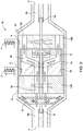
- Figure 2 illustrates a cross sectional view of an embodiment of a rotational flow meter 10 with a single momentum device 14.
- the flow meter 10 is an embodiment of a flow meter component 130 that may be used in a FMU 100 like the one illustrated in Fig. 1 .
- the flow meter 10 is not restricted to an FMU and may be used in any flow system.
- the flow meter 10 of Fig. 2 includes a housing 11, rotatable members 12A and 12B, a momentum device 14 and a torque provider 21.
- the housing 11 forms a chamber 13 which contains the internal components including rotatable members 12A and 12B, momentum device 14 and torque provider 21.
- the housing 11 may contain more or less components.
- FIG. 2 illustrates a cross section of the housing 11.
- the housing 11 has a fluid inlet 4 and a fluid outlet 6.
- housing 11 and the chamber 13 defined therein are both cylindrical.
- a cylindrical chamber 13 facilitates the smooth movement of the internal components in rotation.
- the housing 11 may be made of any number of pieces in order to make the manufacture and assembly of the flow meter easier.
- the housing may be made of two pieces. The first piece may be constructed in the shape of a cylinder, and the second piece may be constructed in the shape of a cap for the cylinder.
- the cylinder and cap are preferably threaded so that they may screw together to seal and form chamber 13.
- the cylinder includes a flange so that the cap may be easily bolted to the cylinder to form the sealed chamber 13.
- An O-ring may be used between the cap and the cylinder to seal the two pieces of the housing 11.
- housing 11 may be used.
- the pieces of the housing 11 may join along a line parallel to the axis of rotation 24 in a clam shell configuration.
- Other configurations are also possible.
- the housing 11 is made from a minimal number of pieces to reduce the number of seals required. Fewer pieces may also reduce manufacturing costs and increase reliability.
- the housing 11 defines a chamber 13 therein.
- the flow meter 10 may be subjected to high internal pressures which will be taken up by the housing 11. Consequently, the housing 11 needs to be sealed against external pressure leaks.
- Mass flow meters may be used in jet engine fuel lines and other extremely high pressure areas and therefore, may be required to withstand high pressures. Pressures in fuel lines may exceed 1,400 pounds per square inch. (psi). Sealing the portions of the housing to form chamber 13 may be done using press fit, threads, an o-ring (not shown) or other commonly used pressure sealing techniques.
- the housing 11 may be made from any material appropriate to handle the fluid the flow meter is designed to withstand. Possible materials for the construction of the housing 11 include injection molded plastic, aluminum, and stainless steel to name a few.
- a rotatable member is defined herein as any component of the flow meter 10 which includes a portion of the flow path 34 that interfaces with the flow path entrance or exit from the momentum device and is designed to rotate with the same angular speed as the momentum device 14 when the flow meter 10 is operating in a steady state condition.
- the fluid enters the flow meter 10 through the fluid inlet 4.
- the torque provider 21 is a turbine and the fluid passes through the turbine which is connected to the shaft 8 running along the axis of rotation 24. As the turbine is caused to rotate by the flowing fluid, the shaft 8 is also caused to rotate.
- the flow path 34 passes through rotatable member 12A, momentum device 14, and rotatable member 12B and then the fluid exits the flow meter 10 via the fluid outlet 6.
- rotatable member 12A and 12B are connected to the rotatable shaft 8 and thus rotate with the shaft.
- Momentum device 14 is also connected to the rotatable shaft 8, however, momentum device 14 is connected to the rotatable shaft via a biasing element 9 (spring). Accordingly, the momentum device 14 will also be caused to rotate with the rotatable shaft 8 as the fluid flows through the flow meter 10, however, the momentum device 14 will lead or lag the rotation of the shaft 8, and the rotatable members 12A and 12B as explained below.
- the flow meter 10 has two rotatable members 12A and 12B.
- only one rotatable member may be present.
- one rotatable member, either 12A or 12B may be stationary and not connected to the rotatable shaft 8 and thus not a rotatable member.
- one of the rotatable members, either 12A or 12B may not be present at all.
- the flow path 34 may not pass through rotatable member 12B and may exit the momentum device 14 directly into the cavity 13.
- rotatable members may be embodied in various different shapes.
- rotatable member 12B is shown in the embodiment of Fig. 2 as a cylinder with a cavity 18 that encloses momentum device 14.
- Rotatable member 12B may also be referred to as a rotor, drum, or a support device for momentum device 14.
- the momentum device 14 is positioned within the cavity 18 of the rotatable member 12B.
- rotatable member 12A acts as a flow conditioner and interfaces with the rotatable member 12B to completely enclose the momentum device 14 in the cavity 18 thus forming a second chamber.
- either rotatable member 12A or 12B may also be used to connect the momentum device 14 to the rotatable shaft 8.
- the momentum device 14 may be connected to either rotatable member 12A or 12B via the biasing element - a torsional spring in the embodiment shown in Fig. 2 . - rather than being connected directly to the rotatable shaft 8.
- the momentum device may be described as connected to a rotatable member, this connection does not have to be a direct connection.
- a reference to the momentum device 14 being connected to a rotatable member includes any connection of the momentum device 14 by a biasing element 9 to any other portion of the flow meter 10 that is being driven by the torque provider 21.
- a biasing element 9 to any other portion of the flow meter 10 that is being driven by the torque provider 21.
- the momentum device 14 is directly connected to the rotatable shaft 8 via the biasing element 9, the connection shown in Fig. 2 may also be described as having the momentum device connected to a rotatable member because the rotatable members 12A and 12B are directly connected to the rotatable shaft 8 which is drive by the torque provider 21.
- an axis of rotation 24 runs from an upstream side 26 of the flow meter 10 to a downstream side 28 of the flow meter 10.
- rotatable member 12A, rotatable member 12B, and the momentum device 14 are designed to rotate about the axis 24.
- the rotatable members and the momentum device 14 may dither back and forth about the axis 24.
- the rotatable members and the momentum device 14 may rotate continuously around the axis 24 or may rotate a certain number of degrees and then reverse direction and rotate back the other direction in a dithered fashion.
- the rotation of the rotatable members 12A and 12B is a forced rotation and may be driven by any number of drive mechanisms or torque providers 21.
- the rotatable members may be rigidly affixed to a shaft 8 that runs down the axis of rotation 24.
- a driver motor exterior to the housing 11 may be the torque provider 21 and spin the rotatable members about the axis of rotation 24.
- the torque provider 21 may be a turbine such as in Fig. 2 , an external motor, or any other drive mechanism suitable for rotating the shaft 8 and the rotatable members continuously or in an alternating dithering fashion back and forth.
- the torque provider 21 or drive system may be upstream or downstream of the momentum device 14.
- the turbine is located downstream of the momentum device 14. Locating the turbine or other drive system downstream of the momentum device 14 helps reduce any turbulence or swirl in the fluid that may be introduced by the drive mechanism. Turbulence and swirl my cause errors in the mass flow measurement and therefore, are undesirable.
- the turbine may be integrated within the housing 11 of the flow meter 10. If the flow meter is within the housing 11, the turbine may be integrated into one of the rotatable members 12A or 12B. In other embodiments, the turbine my be located outside the housing 11 of the flow meter 10.
- the rotatable members 12A and 12B may be directly connected to the torque provider 21.
- the rotatable members may be connected to the torque provider 21 through a series of gears to allow the torque and speed of the rotation to be configured.
- the gear system may be adjustable to allow adjustment of the gear ratio after construction of the flow meter 10 and/or during operation.
- rotatable member 12A is also designed to be a flow conditioner.
- a flow conditioner is used to condition the flow prior to entering the momentum device 14.
- the rotatable member 12A is in fixed rotation with the torque provider 21 and acts as a flow conditioner by causing the flow to rotate with the same angular speed as the momentum device 14 prior to the flow entering the momentum device 14.
- the rotatable member 12A is caused to rotate because it is connected to the rotatable shaft 8 running along the axis 24.
- rotatable member 12A may be connected to rotatable member 12B and caused to rotate as one integrated piece connected to the shaft 8.
- rotatable member 12A and 12B may be designed as a single integrated piece.
- the flow conditioner may be separate from the rotatable members and may not be integrated into a rotatable member.
- the flow conditioner may be stationary or caused to rotate with the rotating components of the flow meter 10.
- the momentum device 14 may be any device designed to measure the momentum of a fluid as it passes through the flow meter 10.
- the momentum device 14 may be a momentum wheel.
- the momentum device 14 is completely enclosed by rotatable member 12A and rotatable member 12B.
- the exemplary embodiment reduces the shear forces experienced by the momentum device 14.
- the shear planes have been moved from the interfaces of the momentum device 14 to the external interfaces of components in fixed rotation with the drive mechanism.
- a shear plane is defined as a plane or area between two adjacent components A and B of the flow meter 10 in which a change in a tangential velocity component of a fluid particle passing from A to B causes a shear force on either A or B.
- a shear plane will often occur between two adjacent components of the flow meter 10 that are not designed to rotate with the same speed when the flow meter 10 has reached a steady state condition.
- a shear plane may exist along where the flow path 34 transitions from a stationary component to a component rotating around the axis of rotation 24.
- the shear planes are located on the downstream side of the rotatable member 12B, and the upstream side of the rotatable member 12A. Hence, the shear planes have been removed from the interfaces where the flow path 34 enters and exits the momentum device 14.
- circumferential shear forces may be experienced on the sides of rotating components as they rotate around the axis of rotation if the sides of the rotating components are adjacent a stationary component.
- circumferential shear forces may exist between the circumference of the rotatable member 12A and the housing 11.
- the momentum device 14 may also be protected from circumferential shear forces. As shown in Fig. 2 , the momentum device is completely enclosed in the cavity 18 and thus the sides of the momentum device 14 are protected from shearing forces that would otherwise be caused by the stationary walls of the housing 11.
- momentum device 14 is completely enclosed in a cavity 18 that rotates or dithers with the same speed as momentum device 14.
- momentum device 14 does not have to be completely enclosed.
- rotatable member 12A may not wrap around and form cavity 18. Consequently, as the momentum device 14 rotates, the sides of the momentum device 14 may be subject to circumferential shear forces with the stationary wall of the housing 11.
- the gap between the momentum device 14 and the walls of the housing 11 may be increased to reduce the circumferential shear forces acting on the sides of the momentum device 14.
- the shear planes may not be removed from both ends of the momentum device 14.
- rotatable member 12A may not be present and may be replaced by a stationary flow conditioner instead that does not rotate around the axis 24, wherein the other rotatable member 12B is still provided. Consequently, a shear plane would exist between the upstream side of the momentum device 14 and the flow conditioner.
- rotatable member 12A may be replaced by a stationary flow conditioner or absent all together, wherein the other rotatable member 12B is still provided.
- the momentum device 14 includes a flow path 34 that determines the path of the fluid through the momentum device 14.
- the embodiment shown in Fig. 2 has a single flow path 34.
- the flow path 34 has a cylindrical cross section along the axis of rotation 24.
- the flow path 34 enters the momentum device 14 on the upstream side 26 with a small diameter and exits the momentum device 14 on the downstream side 28 with a larger diameter.
- the change in diameter which increases the distance of the flow path 34 from the axis of rotation 24 within the momentum device 14, provides a number of benefits as will be discussed below.
- the momentum device 14 In order to determine the mass of the fluid flowing through the mass flow meter 10, the momentum device 14 must add or subtract some measurable amount of angular momentum to the fluid. If the distance of the flow path 34 from the axis of rotation 24 is changed within the momentum device 14, the momentum device 14 may add or subtract angular momentum from the fluid without changing the relative angular speed of the momentum device 14 with respect to the other rotating components of the flow meter 10. The opposite is also true, and if the distance of the fluid path 34 from the axis of rotation 24 is not varied within the momentum device, the momentum device 14 must rotate at a different angular speed with respect to the other components in order to change the angular momentum of the fluid.
- angular momentum In a system with no net torque, angular momentum is conserved.
- Angular momentum is thus the cross product of the vector r and the linear momentum m v .
- Angular momentum is conserved and therefore, r and m v have an inverse relationship.
- Fluid enters the upstream side 26 of the housing 11 from an external line in which it is desired to know the mass flow rate of the fluid.
- the rotatable members 12A and 12B are rigidly affixed to the shaft 8 which is being driven by the torque provider 21 - a turbine in the embodiment of Fig. 2 .
- Rotatable member 12A acts as a rotating flow conditioner and the fluid begins to rotate with the same angular velocity as the rotatable member 12A as the fluid flows through rotatable member 12A.
- the fluid then enters the momentum device 14 with a fixed angular momentum.
- the momentum device 14 As the fluid is forced to move farther away from the axis of rotation 24 by the flow path 34 within the momentum device 14, the angular speed of the fluid volume would normally be reduced to conserve angular momentum. However, the momentum device 14 is affixed to the shaft 8 via a biasing element 9 and is forceably rotated. The momentum device 14 thus increases the angular momentum of the fluid while simultaneously maintaining the angular speed of the fluid about the axis of rotation 24. Although the fluid has maintained the same angular speed, its angular momentum has been increased by the momentum device 14.
- the fluid subsequently leaves the momentum device 14 and enters the rotatable member 12B. Because the rotatable member 12B is also rigidly affixed to the shaft 8, the rotatable member 12B is also rotating with the same angular speed as the momentum device 14 and rotatable member 12A. Thus all three components, rotatable member 12A, rotatable member 12B and the momentum device 14 rotate with the same angular speed.
- the flow meter 10 still has shear planes
- the novel design of the embodiment of Fig. 1 has moved the shear planes from the interface of the momentum device 14 to the exterior of the rotatable members 12A and 12B, which are rigidly affixed to the drive mechanism. Consequently in such embodiments, the shear forces are overcome by the drive mechanism and not by the momentum device 14 and its connecting spring. Therefore, in the steady state condition the flow meter 10 is less sensitive to shear forces and thus less susceptible to errors related to the viscosity and temperature of the fluid.
- the absence of parts rotating at different speeds reduces or eliminates the shearing forces at the interfaces of the momentum device 14. Reducing or removing the shearing planes on the interfaces of the momentum device 14, reduces or eliminates the errors caused by the shear forces. The reduction in shear forces and their associated errors allows the mass flow meter 10 to more accurately calculate the mass of the flowing fluid, especially in variable temperature environments or for fluids with non-uniform viscosities.
- the flow entering or exiting the momentum device may be conditioned to further increase the accuracy of the flow meter 10.
- Flow straighteners 30 and 32 may be added directly before and after the momentum device 14 to increase the uniformity of the flow entering and exiting the momentum device 14.
- the flow straighteners 30 and 32 are integrated into rotatable members 12A and 12B respectively and rotate with the same speed as the momentum device 14.
- the flow straighteners 30 and 32 may be separate parts and may not rotate. If flow straighteners 30 and 32 are separate parts, they may be driven by the same motor or gears as the rotatable members or may be driven by a separate drive system.
- the flow straighteners 30 and 32 may be rigidly affixed to the shaft to cause them to rotate in unison with the rotatable members and the momentum device 14. In embodiments where the flow straighteners do not rotate, they will not need to be connected to any part of the drive system. In addition, any number of flow straighteners may be used. Furthermore in other embodiments, more than one flow straightener may be used prior to or after the momentum device 14. In certain embodiments, flow straighteners may also be included in the pipe before or after entering the flow meter 10.
- An important function of the flow straighteners 30 and 32 is to reduce or minimize swirl.
- Swirl is any additional currents in an axial flow, such as may be present after sharp bends or other obstacles in the flow path.
- a fluid flow that includes swirl has additional components of angular momentum which may add or subtract angular momentum to the fluid about the axis of rotation 24 of the flow meter 10. This additional angular momentum may introduce errors into the mass flow calculations.
- the flow straighteners 30 and 32 help reduce and minimize the swirl and turbulence prior to and after the fluid exits the momentum device 14 so that an accurate measurement of the angular momentum and thus mass flow rate may be made.
- the flow straighteners 30 and 32 are shown in Fig. 1 as straight portions of the flow path 34 on the upstream and downstream sides of the momentum device 14.
- the flow straighteners may be any shape, size or length that helps reduce the swirl and turbulence of the fluid as it enters and exits the momentum device 14.
- the frictional torque may be approximated as follows:
- the torque T s generated by the shear stress can be approximated with T s ⁇ A * ⁇ * r 1 where r 1 is the mean entry radius and A is the entry area of the fluid at the momentum device 14.
- the flow path 34 through the momentum device 14 may take many possible shapes and include any number of paths.
- the flow path 34 through the device may be made of several individual flow paths that branch out from a central flow path.
- the flow path 34 may be a ring of increasing or decreasing diameter.
- the flow path 34 may be made of multiple parallel paths.
- the flow path 34 may be split into several parallel sections which are separated by radial vanes.
- the flow path 34 may be angled outward or inward or take any other path that changes the distance of the flow path 34 from the axis of rotation 24.
- Fig. 2 illustrates a flow path 34 that increases in radial distance, an "inside out” flow path.
- Other flow path shapes that change in radial distance may be used.
- an "outside in” flow path may be used. The reduction of the radial distance of the flow path in an "outside in” shape will cause the momentum device to speed up or lead the rotatable members rather than slow down or lag the rotatable members as caused by the "inside out” path.
- the mass flow meter 10 may measure the torque required to slow down the momentum device 14 to match the angular speed of the rotatable member 12B and surrounding parts.
- any flow path or paths 34 may be used through the momentum device 14 that include(s) a change in radial distance from the axis of rotation.
- the angles and shape of the path(s) may be optimized to help reduce swirl and other turbulence that may be part of the fluid flow.
- the flow path 34 may be advantageous for the flow path 34 to pass through certain components of the flow meter 10 while in other embodiments, it may be advantageous for the flow path 34 to pass around certain components.
- having the flow path 34 pass through the rotatable member 12B allows for a compact design and may reduce the number of components required while still separating at least one shearing planes from the interface of the momentum device 14.
- the momentum device 14 is preferably connected to the rotatable member 12B via a biasing element 9 such as a spring.
- a biasing element 9 such as a spring.
- the momentum device 14 may be connected to the mass flow meter 10 in a number of ways. If a spring is used, the spring constant, which is the measure of the force required for a particular deflection, needs to be carefully calibrated in order to allow the spring to accurately measure the torque imparted on the passing fluid as the momentum device 14 rotates.
- the rotatable members 12A and 12B are forceably caused to rotate by the turbine or other torque provider 21.
- the spring connecting the momentum device 14 to the rotatable member 12B, or other rotating component such as the shaft 8, forces the momentum device 14 to rotate with the rotatable member 12B.
- the forced rotation of the momentum device 14 via the spring at a certain angular speed will increase the angular momentum of the fluid as the flow path of the fluid increases in distance from the axis of rotation 24.
- the corresponding torque on the momentum device 14 as it adds angular momentum to the flowing fluid will cause the spring connecting the momentum device 14 to the rotatable member 12B to deflect.
- the deflection may be translated into a torque measurement by using the carefully calibrated spring constant.
- a spring is preferably used as the biasing element 9 to connect the momentum device 14 to the rotatable member either 12A or 12B
- any biasing element capable of being calibrated to indicate the torque on the momentum device 14 may be used.
- a spring is used as the biasing element 9
- different types of springs may be used.
- a torsional spring, a spiral spring, a torsion bar, a compression spring, or an extension spring may be used to connect the momentum device 14 to the rotatable member 12B.
- the spring constant is adjustable to allow fine adjustments to the flow meter 10 to be made easily during the calibration process.
- the momentum device 14 has to rotate freely around the axis of rotation 24.
- the momentum device 14 is constrained to the flow meter 10 by the biasing element 9 but should otherwise rotate freely about the axis of rotation 24. Friction due to the rotation of the momentum device 14 will contribute to any error in the mass flow calculations.
- the momentum device 14 is mounted on bearings around the axis of rotation 24.
- the momentum device 14 may be connected using other methods including ball or rolling bearings, magnetic bearings, sleeve bearings, jewel bearings, high pressure hydraulic bearings or any other type of low friction connection that will allow the momentum device 14 to rotate freely.
- the friction in the bearing is prevailingly responsible for hysteresis and depends on the mechanical load both axially and radially.
- a hydraulic bearing may be used to allow the momentum device 14 to rotate freely around the axis of rotation 24.
- the axial load may be compensated by applying the same pressure at the back of the momentum device 14 as at the front of the momentum device 14.
- the flow meter 10 is designed to allow small amounts of the liquid to purposely leak into areas between the momentum device 14 and the walls of the cavity 18 and/or shaft to form a hydraulic bearing.
- the "leak” would further serve to keep the pressure equal both radially and axially.
- liquid is allowed to leak into the chamber 13 formed between the housing 11 and internal components.
- a permanent magnet such as a magnet bearing
- the levitation eliminates friction between the momentum device 14 and the rest of the flow meter 10.
- hysteresis may be reduced or removed by using the permanent magnet bearing.
- the momentum device 14 As the momentum device 14 rotates around the axis of rotation 24 and the angular momentum of the liquid is increased accordingly, the spring connecting the momentum device is deflected. This deflection needs to be accurately measured in order to calculate the torque exerted on the momentum device 14 by the fluid. Once in the steady state condition, the momentum device 14 will rotate with the same speed as the rotatable members. However, due to the spring connection and the constant force the momentum device 14 must exert to change the angular momentum of the passing fluid, the momentum device 14 will lag or lead the rotation of the rotatable members. This phase shift in rotation may be measured to determine the deflection of the spring.
- magnetic pickups are used to measure the phase shift in the rotation of the momentum device 14 and the rotatable member 12B.
- Magnetic pickups consist of a magnet 5 that travels in close proximity past a coiled wire 7. As the magnet 5 passes the coiled wire 7 a current is induced in the wire which may be measured as a signal.
- a magnet 5 By placing a magnet 5 on both the rotating rotatable member 12B, and the rotating momentum device 14, the relative rotation of the rotatable member 12B to the momentum device 14 may be determined.
- an electrical current is induced in the coil which may be monitored as a signal.
- the difference in time between when the rotatable member 12B passes the wire coil pickup 7 and when the momentum device 14 passes the wire coil pickup 7 is the phase shift needed to determine the spring deflection.
- the momentum device 14 and rotatable member 12B are used as the two rotating components for which a phase shift is determined as shown in Fig. 2
- other components other than the rotatable member 12B may be used.
- the phase shift may be measured between the momentum device 14 and any other component in fixed rotation.
- the phase shift may be determined between the momentum device 14 and a rotatable shaft 8 or the rotatable member 12A.
- the magnet 5 may be relocated from the rotatable member 12B to the other rotatable component.
- Other configurations of the magnets 5 and the wire coils 7 are also possible.
- the magnets 5 may be configured on the momentum device 14 and rotatable members in numerous ways.
- the magnets 5 could be configured on the exterior or interior of the flow meter 10.
- the magnets could each have their own coil wire pickup or could share a coil wire pickup 7.
- a single coil pickup 7 sensor may be used for both the rotatable member 12B and the momentum device 14.
- a current will be induced in the opposite direction for each magnet 5. The reverse in the direction of the current may be used to distinguish the signal of the rotatable member 12B from the signal of the momentum device 14.
- the two parts may share a single coil wire pickup 7. Reducing the number of coil pickups 7 reduces the number of parts, reduces cost, and increases reliability. In addition, the required wiring may be reduced. Other methods of detecting the spring deflection may also be used including capacitive, inductive, optical, or Eddy current based methods.
- magnets may be placed inside the coil wire pickups 7. Ferrite targets are then mounted on the rotating components instead of magnets. When the ferrite targets pass by the pickups 7, the magnetic flux in the pickups 7 will change and thereby induce a voltage in the coil that can be detected.
- the internal components such as the rotatable members 12A and 12B and the momentum device 14, may be made out of any material appropriate for the fluid that will flow through them.
- the internal components may be made from injection molded plastic, stainless steel or aluminum or any other suitable metal, plastic, ceramic or other material.
- Figure 3 illustrates a cross sectional view of an embodiment of a dithered mass flow meter 50.
- the mass flow meter 50 shown in Fig. 3 also includes an additional momentum device 15. Adding an additional momentum device 15 provides redundant measurements and helps calculate a more accurate mass flow reading.
- the torque outputs of the momentum devices 14 and 15 may be averaged or simply added or compared to increase the accuracy of the overall mass flow measurement.
- the embodiments of Fig. 2 and Fig. 3 show one momentum device and two momentum devices respectively, any number of momentum devices may be added to increase the torque, and thereby accuracy, or to provide redundant measurements.
- An additional advantage of the embodiment of the flow meter 50 in Fig. 3 over the flow meter 10 in Fig. 2 is that the input and output diameters of the inlet and outlet of the flow path 34 passing through the momentum devices 14 and 15 are the same.
- the first momentum device 14 increases the diameter of the flow path 34 and the second momentum device 15 returns the diameter of the flow path 34 to its original diameter.
- the inlet and outlet the same diameter is preferable because it allows the flow meter 50 to be placed directly inline within an existing pipe without further modification.
- adding an additional "outside in" momentum device is not required to return the flow path 34 to its input diameter.
- Flow meter 10 may return the flow path 34 to its entry diameter within the housing 11 without adding an additional momentum device 15.
- additional momentum devices may be used without returning the flow path to its original diameter.
- certain embodiment may include multiple momentum devices while still increasing or decreasing the exit diameter of the flow path 34 from the entry diameter of the flow path 34.
- Flow meter 50 includes rotatable members 60A and 60B. Rotatable members 60A and 60B integrate together to form cavity 18 in which momentum devices 14 and 15 are located. Rotatable members 60A and 60B have flow conditioners 30 and 32 integrated into them respectively.
- the flow meter 50 includes and external motor 56 as a torque provider.
- the external motor 56 drives the rotatable components via a gear system 58.
- the external motor 56 is designed to switch directions at periodic intervals causing the rotatable members 60A and 60B to dither back and forth on the fixed shaft 62.
- Momentum devices 14 and 15 are connected to the rotatable members 60A and 60B by four biasing elements 52.
- the biasing elements 52 are springs. As the rotatable members are dithered back and forth the momentum devices 14 and 15 are forced to follow the rotatable members via their connection via the biasing elements 52.
- the fluid As the fluid flows through the flow meter 50, it enters the momentum device 14 at an initial radius r1 and exits the momentum device 14 at a larger radius r2. The change in the radius of the flow path 34 within the momentum device 14 causes the momentum device 14 to lag the rotatable members 60A and 60B. The fluid then enters the second momentum device 15 at radius r3 and exits the second momentum device 15 at a smaller radius r4. The reduction of the radius of the flow path 34 within the second momentum device 15 cause the momentum device to lead the rotatable members 60A and 60B.
- r1 is equal to r4 and r2 is equal to r3 resulting in no net change in the flow path radius as it passes through the flow meter 50.
- flow meter 10 in Fig. 2 other flow path designs are possible.
- the rotating parts in flow meter 50 are driven by an external motor 56 and rotate around a fixed shaft 62.
- the rotating parts may be supported on the shaft by bearings or any other method of allowing the parts to rotate with as little friction as possible.
- the integrated rotatable members 60A and 60B are supported on the shaft 62 via bearings located in the center and along the axis of the flow straightener portions 30 and 32 of the rotatable members 60A and 60B.
- the flow meter embodied in Fig. 3 also uses Hall effect sensors 54 to determine the position of the momentum devices 14 and 15.
- the Hall effect sensors measure a change in magnetic field and may be used in combination with magnets 5 as one alternative to the wire coil pickups shown in the embodiment of Fig. 2 . As the magnets dither back and forth the magnetic field sensed by the Hall effect sensor will change.
- the Hall effect sensor 54 will use the change in the magnetic field to determine the relative position of momentum devices 14 and 15.
- a magnet 5 may be placed on each momentum device rather than on a momentum device and a rotatable member as illustrated in the embodiment of Fig. 2 . Because the design of the flow path 34 of flow meter 50 will cause momentum device 14 to lead the rotatable members and the momentum device 15 to lag the rotatable members, the relative difference between the momentum devices may be used to determine the mass flow rate via the Hall effect sensors 54.
- the embodiment shown in Fig. 3 has some differences from the embodiment of Fig. 2 , the embodiment of Fig. 3 still has a flow path 34 that passes through the momentum device and then enters rotatable members designed to remove a shear plane from the interface of the momentum device itself.
- the design elements of the embodiments shown in Fig. 2 and Fig. 3 are interchangeable.
- an embodiment of a flow meter may use two momentum devices but rotate instead of dither.
- an embodiment of a flow meter may use a motor contained within the housing 11 or a turbine external to the housing 11.
- Figure 4 illustrates a cross sectional view of an embodiment of a mass flow meter 200.
- the mass flow meter 200 is similar to mass flow meter 10 in Fig. 2 except that it includes a momentum device 14 on which the entry and exit of the flow path are on the same side.
- the general flow direction of the flow path 34 is substantially reversed within the momentum device 14.
- the fluid enters at a radius r1 from the axis of rotation 24 and the fluid exits at a radius r2 from the axis of rotation 24. Both the fluid entrance and fluid exit are on the same side of the flow meter 200. Allowing the fluid to enter and exit the flow meter 200 on the same side allows the flow meter 200 to be installed in tight places where a flow meter that allows the fluid to pass through, such as flow meter 10 shown in Fig. 2 , will not fit.
- flow meter 200 allows the torque provider to be more easily mounted on the exterior and provide the torque to a shaft running along the axis of rotation 24.
- the torque provider is an external motor 56 mounted coaxially with the axis of rotation 24.
- the internal components are similar to the embodiment of flow meter 10. Although some of the internal components may have slightly different dimensions to adapt for the different geometry, they have the same function as described in the detailed description of flow meter 10.
- the fluid enters the mass flow meter 200 through rotatable member 210A before it enters the momentum device 14 at a radius r1 from the axis of rotation 24.
- the rotatable member 210A will be connected to the rotatable member 210B and will be rotating together with the rotatable member 210B.
- the rotatable member 210A may just be fixed to the housing near the fluid inlet and will be stationary.
- the rotatable member 210A may be omitted completely and the fluid enters directly into the momentum device 14.
- the rotatable members 210A and 210B may have flow conditioners 30 and 32 integrated into them respectively.
- the flow conditioners may be flow straighteners.
- the fluid will be transferred from radius r1 to radius r2 within the rotating momentum device 14, thereby changing the fluid's angular momentum.
- the fluid exits the momentum device 14 at radius r2 and enters the rotatable member 210B.
- the rotatable member 210B is shaped to form the cavity 18.
- the additional cover plate 19 closes the cavity 18 to close out the shear plane between the momentum device 14 and the housing 11.
- the fluid After exiting the rotatable member 210B, the fluid enters a ring channel 35.
- the ring channel 35 collects all the fluid and leads it to the fluid outlet 36.
- the fluid outlet 36 is situated on the same side of the housing 11 as the fluid inlet. In other mass flow meter embodiments, the fluid outlet 36 may be on the circumference of the housing 11 and lead radially outward from the ring channel 35.
- the fluid is shown entering and exiting on the same side of the flow meter 200 at radii r1 and r2 in Fig. 4 , other configurations for the entry and exit are possible while still including a momentum device 14 that substantially reverses the direction of the flow path 34.
- the flow path might still allow the fluid to pass through the flow meter despite flowing through a momentum device 14 that substantially changes the direction of the fluid flow.
- more than one momentum device 14 that substantially reverses the direction of the fluid flow may be used in combination within the same flow meter.
- the fluid entrance and exit may be on sides that are oriented ninety degrees from each other.
- the fluid path 34 may be designed to allow the fluid entrance and exit to be on any side of the flow meter. Momentum devices that either substantially reverse the flow, allow the flow to pass through, and combinations thereof, may be incorporated to create various flow paths and various fluid entrance and exit locations.
- the mass flow meter is mounted on the exterior of a hydraulic unit, such as the fuel metering unit 100 shown in Fig. 1 ., from which the fluid comes from and to which the fluid must return again.
- the advantage of the mass flow meter 200 is that it can be mounted directly on the hydraulic unit without additional pipe work.
- One advantage of the embodiment of the flow meter 200 in Fig. 4 is that the overall length of the mass flow meter may be substantially reduced.
- the overall length of the mass flow meter that reverses the direction of the fluid flow may be reduced to about half the length of the mass flow meter that allows the fluid to pass through.
- the overall weight may be reduced accordingly.
- the walls of the housing 11 may be required to have a substantial thickness when the specified static pressure is high.
- the weight of the housing is therefore predominant in many cases. The possible reduction in length may therefore allow the weight of the mass flow meter to be reduced by almost half.
- Figure 5 illustrates a cross sectional view of an embodiment of a mass flow meter 300 in which the flow path enters and exits the flow meter on the same side.
- the embodiment shown in Fig. 5 does not use a momentum device that substantially reverses the direction of the fluid flow. Instead the fluid flow is reversed within the housing 11.
- different embodiments of the flow meter may be designed to allow the fluid to enter and exit the flow meter on any side and in any combination.
- the fluid exits the rotatable member 12 and enters into the housing 11 where the flow path 302 directs the fluid back around the flow meter to the same side it entered on.
Landscapes
- Physics & Mathematics (AREA)
- Fluid Mechanics (AREA)
- General Physics & Mathematics (AREA)
- Measuring Volume Flow (AREA)
Claims (19)
- Massendurchflussmesser (10, 50, 130, 200, 300), enthaltend:ein Gehäuse (11) mit einem Fluideinlass (4) und einem Fluidauslass (6, 36), wobei das Gehäuse (11) eine Kammer begrenzt;ein drehbares Element (12A, 12B, 60A, 60B, 210A, 210B), das in der Kammer (13) angeordnet und um eine Achse (24) drehbar ist;eine Schwungvorrichtung (14, 15), definiert als eine gegenüber dem drehbaren Element drehbare Vorrichtung, wobei die Schwungvorrichtung (14, 15) in der Kammer (13) angeordnet und über eine Verbindung, die ein Spannelement (9, 52) aufweist, derart mit dem drehbaren Element (12A, 12B, 60A, 60B, 210A, 210B) verbunden ist, dass sie um die Achse (24) und gegenüber dem drehbaren Element (12A, 12B, 60A, 60B, 210A, 210B) drehbar ist; undeinen Fluidweg (34), der mit dem Fluideinlass (4) und dem Fluidauslass (6, 36) in Fluidverbindung steht, wobei der Fluidweg (34) sowohl durch das drehbare Element (12A, 12B, 60A, 60B, 210A, 210B) als auch durch die Schwungvorrichtung (14, 15) verläuft, und wobei der Fluidweg (34) in einem radialen Abstand r1 von der Achse (24) in die Schwungvorrichtung eintritt und in einem radialen Abstand r2 von der Achse (24) aus der Schwungvorrichtung austritt, und wobei r1 und r2 unterschiedliche Abstände sind, so dass der durch die Schwungvorrichtung (14, 15) verlaufende Fluidweg (34) eine Änderung des Abstands von der Achse (24) aufweist.
- Massendurchflussmesser nach Anspruch 1, weiter enthaltend:eine zweite Schwungvorrichtung (15), die in der Kammer (13) angeordnet und über ein Spannelement (9, 52) derart mit dem drehbaren Element (12A, 12B, 60A, 60B, 210A, 210B) verbunden ist, dass sie um die Achse (24) und gegenüber dem drehbaren Element (12A, 12B, 60A, 60B, 210A, 210B) drehbar ist; undwobei der Fluidweg (34) durch die zweite Schwungvorrichtung (15) verläuft, und wobei der Fluidweg (34) in einem radialen Abstand r3 von der Achse (24) in die zweite Schwungvorrichtung (15) eintritt und in einem radialen Abstand r4 von der Achse (24) aus der zweiten Schwungvorrichtung (15) austritt, wobei r3 und r4 unterschiedliche Abstände sind.
- Massendurchflussmesser nach Anspruch 1 oder 2, weiter enthaltend einen innerhalb der Kammer angeordneten Strömungsgleichrichter (30, 32), wobei ein Teil des Fluidwegs (34) zwischen dem Fluideinlass (4) und der Schwungvorrichtung (14, 15) vom Strömungsgleichrichter (30, 32) begrenzt ist.
- Massendurchflussmesser nach Anspruch 3, wobei der Strömungsgleichrichter (30, 32) dazu ausgebildet ist, mit dem drehbaren Element (12A, 12B, 60A, 60B, 210A, 210B) fest mitzudrehen.
- Massendurchflussmesser nach Anspruch 3 oder 4, wobei der Strömungsgleichrichter (30, 32) mindestens einen Teil des Fluidwegs (34) innerhalb des drehbaren Elements (12A, 12B, 60A, 60B, 210A, 210B) umfasst.
- Massendurchflussmesser nach mindestens einem der Ansprüche 1 bis 5, wobei das drehbare Element (12A, 12B, 60A, 60B, 210A, 210B) eine zweite Kammer (18) begrenzt und die Schwungvorrichtung (14, 15) in der zweiten Kammer (18) angeordnet ist.
- Massendurchflussmesser nach mindestens einem der Ansprüche 1 bis 6, weiter enthaltend eine entlang der Achse (24) verlaufende drehbare Welle (8, 62).
- Massendurchflussmesser nach mindestens einem der Ansprüche 1 bis 7, weiter enthaltend eine mit dem drehbaren Element (12A, 12B, 60A, 60B, 210A, 210B) gekoppelte Drehmomentabgabevorrichtung.
- Massendurchflussmesser nach Anspruch 7 und 8, wobei die Drehmomentabgabevorrichtung über die drehbare Welle (8, 62) mit dem drehbaren Element (12A, 12B, 60A, 60B, 210A, 210B) gekoppelt und die Schwungvorrichtung (14, 15) über das Spannelement (9, 52) mit der drehbaren Welle (8, 62) verbunden ist.
- Massendurchflussmesser nach mindestens einem der Ansprüche 1 bis 9, wobei das Spannelement (9, 52) eine Feder ist.
- Massendurchflussmesser nach mindestens einem der Ansprüche 8 bis 10, wobei die Drehmomentabgabevorrichtung (21, 56) eine Turbine und/oder ein Motor ist.
- Massendurchflussmesser nach mindestens einem der Ansprüche 1 bis 11, wobei r1 kleiner als r2 ist.
- Massendurchflussmesser nach mindestens einem der Ansprüche 8 bis 12, wobei das drehbare Element (12A, 12B, 60A, 60B, 210A, 210B) und die Schwungvorrichtung (14, 15) dazu ausgebildet sind, von der Drehmomentabgabevorrichtung (21, 56) kontinuierlich in der gleichen Drehrichtung angetrieben zu werden.
- Massendurchflussmesser nach mindestens einem der Ansprüche 8 bis 12, wobei das drehbare Element (12A, 12B, 60A, 60B, 210A, 210B) und die Schwungvorrichtung (14, 15) dazu ausgebildet sind, von der Drehmomentabgabevorrichtung (21, 56) hin und her bewegt zu werden.
- Massendurchflussmesser nach mindestens einem der Ansprüche 1 bis 14, weiter enthaltend mindestens einen Sensor (7, 54), der dazu ausgebildet ist, mindestensdie Auslenkung des Spannelements (9, 52),eine Winkelgeschwindigkeit der Schwungvorrichtung (14, 15),ein Drehmoment zwischen der Schwungvorrichtung (14, 15) und dem drehbaren Element (12A, 12B, 60A, 60B, 210A, 210B)und/oder die Phasendifferenz zwischen der Schwungvorrichtung (14, 15) und dem drehbaren Element (12A, 12B, 60A, 60B, 210A, 210B) zu messen.
- Massendurchflussmesser nach mindestens einem der Ansprüche 1 bis 15, wobei das Fluid auf ein und derselben Seite der Schwungvorrichtung (14, 15) in diese ein- und aus dieser austritt.
- Massendurchflussmesser nach mindestens einem der Ansprüche 1 bis 16, wobei in der Schwungvorrichtung (14, 15) eine Fliessrichtung des Fluidwegs (34) im Wesentlichen umgekehrt wird.
- Massendurchflussmesser nach mindestens einem der Ansprüche 2 bis 17, wobei die Änderung des radialen Abstands zwischen r1 und r2 im Wesentlichen gleich gross ist wie die Änderung des radialen Abstands zwischen r3 und r4 und die entgegengesetzte Richtung aufweist.
- Kraftstoffzumesseinheit (100) mit einem Durchflussmesser (10, 50, 130, 200, 300) nach mindestens einem der Ansprüche 1 bis 18.
Applications Claiming Priority (1)
| Application Number | Priority Date | Filing Date | Title |
|---|---|---|---|
| US13/010,560 US8353221B2 (en) | 2011-01-20 | 2011-01-20 | Mass flow meter |
Publications (2)
| Publication Number | Publication Date |
|---|---|
| EP2485019A1 EP2485019A1 (de) | 2012-08-08 |
| EP2485019B1 true EP2485019B1 (de) | 2018-02-28 |
Family
ID=45491462
Family Applications (1)
| Application Number | Title | Priority Date | Filing Date |
|---|---|---|---|
| EP12151684.3A Active EP2485019B1 (de) | 2011-01-20 | 2012-01-19 | Massendurchflussmesser |
Country Status (5)
| Country | Link |
|---|---|
| US (1) | US8353221B2 (de) |
| EP (1) | EP2485019B1 (de) |
| CN (1) | CN102607655B (de) |
| CA (1) | CA2764083C (de) |
| ES (1) | ES2663600T3 (de) |
Families Citing this family (10)
| Publication number | Priority date | Publication date | Assignee | Title |
|---|---|---|---|---|
| US9506785B2 (en) | 2013-03-15 | 2016-11-29 | Rain Bird Corporation | Remote flow rate measuring |
| CN104713601A (zh) * | 2013-12-17 | 2015-06-17 | 奚勇 | 一种自转式流量计 |
| WO2018013857A1 (en) | 2016-07-13 | 2018-01-18 | Rain Bird Corporation | Flow sensor |
| WO2019029837A1 (de) * | 2017-08-09 | 2019-02-14 | Diehl Metering Gmbh | Messeinrichtung zur ermittlung einer ein fluid und/oder eine fluidströmung betreffenden fluidgrösse |
| US10473494B2 (en) | 2017-10-24 | 2019-11-12 | Rain Bird Corporation | Flow sensor |
| US11662242B2 (en) | 2018-12-31 | 2023-05-30 | Rain Bird Corporation | Flow sensor gauge |
| SE544909C2 (en) * | 2019-12-20 | 2022-12-27 | Dover Fueling Solutions Uk Ltd | A fuel dispenser for refueling vehicles comprising a reduced number of electric cables |
| US10753779B1 (en) * | 2020-03-02 | 2020-08-25 | John F. Foss | Mass flow meter |
| US11874149B2 (en) | 2020-04-27 | 2024-01-16 | Rain Bird Corporation | Irrigation flow sensor systems and methods of detecting irrigation flow |
| US12443208B2 (en) | 2023-02-08 | 2025-10-14 | Rain Bird Corporation | Control zone devices, systems and methods |
Family Cites Families (23)
| Publication number | Priority date | Publication date | Assignee | Title |
|---|---|---|---|---|
| GB717897A (en) | 1951-12-06 | 1954-11-03 | Gen Electric | Improvements in and relating to fluid flow measuring instruments |
| US3036461A (en) * | 1959-02-03 | 1962-05-29 | Gen Electric | Flowmeter |
| US3232110A (en) * | 1962-01-24 | 1966-02-01 | Yao T Li | Mass flow meter |
| US3538767A (en) | 1968-12-04 | 1970-11-10 | Gen Electric | Flowmeter fluid drive |
| US3613451A (en) | 1969-10-24 | 1971-10-19 | Bendix Corp | Mass flowmeter |
| JPS5336339B1 (de) | 1971-02-18 | 1978-10-02 | ||
| US3877304A (en) | 1971-02-18 | 1975-04-15 | Eldec Corp | Flowmeter |
| US3807229A (en) * | 1972-03-01 | 1974-04-30 | Electro Dev Corp | Bypass flowmeter |
| US3958447A (en) * | 1975-07-09 | 1976-05-25 | Eldec Corporation | Mass flowmeter |
| US4012957A (en) | 1976-04-27 | 1977-03-22 | Eldec Corporation | Shrouded flowmeter turbine and improved fluid flowmeter using the same |
| US4056976A (en) | 1976-10-12 | 1977-11-08 | General Electric Company | Mass rate of flow meter |
| US4248099A (en) | 1979-10-12 | 1981-02-03 | General Electric Company | Mass rate of flow meter with improved fluid drive |
| US4279168A (en) | 1979-10-12 | 1981-07-21 | General Electric Company | Mass rate of flow meter with electromagnetic interference compensation |
| US4438648A (en) * | 1982-06-18 | 1984-03-27 | Eldec Corporation | Differential mass flowmeter |
| US4534226A (en) * | 1983-11-01 | 1985-08-13 | General Electric Company | Counter rotating, multi turbine flow measuring system |
| US5370001A (en) * | 1993-06-02 | 1994-12-06 | Ametek, Inc. | Angular momentum mass flowmeter |
| US5363699A (en) * | 1993-08-25 | 1994-11-15 | Ketema, Inc. | Method and apparatus for determining characteristics of fluid flow |
| FR2721999B1 (fr) | 1994-06-30 | 1996-08-09 | Contruction De Moteurs D Aviat | Debimetre massique redondant |
| US5728950A (en) | 1996-05-20 | 1998-03-17 | Ametek Aerospace Products, Inc. | Fluid flowmeter |
| GB2390691B (en) * | 2002-07-11 | 2005-11-23 | Rolls Royce Plc | Measurement of fuel flow |
| US7603915B2 (en) | 2007-08-23 | 2009-10-20 | Rosemount Aerospace Inc. | Force balanced impeller flow meter for mass flow rate control |
| US7784359B2 (en) | 2008-04-17 | 2010-08-31 | Rosemount Aerospace Inc. | Coriolis effect mass flow meter and gyroscope |
| US8205508B2 (en) * | 2010-01-12 | 2012-06-26 | Meggitt (New Hampshire), Inc. | Motorless mass flowmeter |
-
2011
- 2011-01-20 US US13/010,560 patent/US8353221B2/en active Active
-
2012
- 2012-01-13 CA CA2764083A patent/CA2764083C/en active Active
- 2012-01-19 ES ES12151684.3T patent/ES2663600T3/es active Active
- 2012-01-19 EP EP12151684.3A patent/EP2485019B1/de active Active
- 2012-01-20 CN CN201210018289.0A patent/CN102607655B/zh active Active
Non-Patent Citations (1)
| Title |
|---|
| None * |
Also Published As
| Publication number | Publication date |
|---|---|
| CN102607655B (zh) | 2016-12-14 |
| CN102607655A (zh) | 2012-07-25 |
| ES2663600T3 (es) | 2018-04-16 |
| EP2485019A1 (de) | 2012-08-08 |
| US8353221B2 (en) | 2013-01-15 |
| CA2764083A1 (en) | 2012-07-20 |
| US20120186361A1 (en) | 2012-07-26 |
| CA2764083C (en) | 2019-01-22 |
Similar Documents
| Publication | Publication Date | Title |
|---|---|---|
| US8353221B2 (en) | Mass flow meter | |
| JP2989896B2 (ja) | 同心ロータを用いるコリオリ効果質量流量計 | |
| US6412338B2 (en) | On-board rotational viscometers | |
| EP2104843B1 (de) | Halleffekt-helikopter-mast-drehmomentmesser | |
| RU2182695C2 (ru) | Массовый расходомер, использующий эффект кориолиса, с одним ротором, имеющим гибкий чувствительный элемент, и способ эксплуатации этого расходомера | |
| US5370001A (en) | Angular momentum mass flowmeter | |
| US6257051B1 (en) | On-board rotational viscometers | |
| EP0032910A1 (de) | Durchflussmesser für turbinen. | |
| US3232110A (en) | Mass flow meter | |
| CN107489609A (zh) | 立式间隙流动动力特性系数测试装置 | |
| US5429003A (en) | Moving sensor linear true mass flowmeter | |
| US4449414A (en) | Fluid-responsive apparatus | |
| JPS6199818A (ja) | 容積式流量計 | |
| JPH0148969B2 (de) | ||
| GB2099148A (en) | Fluid-responsive apparatus | |
| JP3715049B2 (ja) | 流速・運動量式質量流量測定装置 | |
| WO2004097359A1 (en) | Monitoring of load in a gear unit | |
| JPH0148967B2 (de) |
Legal Events
| Date | Code | Title | Description |
|---|---|---|---|
| PUAI | Public reference made under article 153(3) epc to a published international application that has entered the european phase |
Free format text: ORIGINAL CODE: 0009012 |
|
| AK | Designated contracting states |
Kind code of ref document: A1 Designated state(s): AL AT BE BG CH CY CZ DE DK EE ES FI FR GB GR HR HU IE IS IT LI LT LU LV MC MK MT NL NO PL PT RO RS SE SI SK SM TR |
|
| AX | Request for extension of the european patent |
Extension state: BA ME |
|
| 17P | Request for examination filed |
Effective date: 20130125 |
|
| STAA | Information on the status of an ep patent application or granted ep patent |
Free format text: STATUS: EXAMINATION IS IN PROGRESS |
|
| 17Q | First examination report despatched |
Effective date: 20161123 |
|
| GRAP | Despatch of communication of intention to grant a patent |
Free format text: ORIGINAL CODE: EPIDOSNIGR1 |
|
| STAA | Information on the status of an ep patent application or granted ep patent |
Free format text: STATUS: GRANT OF PATENT IS INTENDED |
|
| INTG | Intention to grant announced |
Effective date: 20170915 |
|
| GRAS | Grant fee paid |
Free format text: ORIGINAL CODE: EPIDOSNIGR3 |
|
| GRAA | (expected) grant |
Free format text: ORIGINAL CODE: 0009210 |
|
| STAA | Information on the status of an ep patent application or granted ep patent |
Free format text: STATUS: THE PATENT HAS BEEN GRANTED |
|
| AK | Designated contracting states |
Kind code of ref document: B1 Designated state(s): AL AT BE BG CH CY CZ DE DK EE ES FI FR GB GR HR HU IE IS IT LI LT LU LV MC MK MT NL NO PL PT RO RS SE SI SK SM TR |
|
| REG | Reference to a national code |
Ref country code: GB Ref legal event code: FG4D Ref country code: CH Ref legal event code: EP |
|
| REG | Reference to a national code |
Ref country code: AT Ref legal event code: REF Ref document number: 974645 Country of ref document: AT Kind code of ref document: T Effective date: 20180315 |
|
| REG | Reference to a national code |
Ref country code: IE Ref legal event code: FG4D |
|
| REG | Reference to a national code |
Ref country code: DE Ref legal event code: R096 Ref document number: 602012043264 Country of ref document: DE |
|
| REG | Reference to a national code |
Ref country code: ES Ref legal event code: FG2A Ref document number: 2663600 Country of ref document: ES Kind code of ref document: T3 Effective date: 20180416 |
|
| REG | Reference to a national code |
Ref country code: NL Ref legal event code: MP Effective date: 20180228 |
|
| REG | Reference to a national code |
Ref country code: LT Ref legal event code: MG4D |
|
| REG | Reference to a national code |
Ref country code: AT Ref legal event code: MK05 Ref document number: 974645 Country of ref document: AT Kind code of ref document: T Effective date: 20180228 |
|
| PG25 | Lapsed in a contracting state [announced via postgrant information from national office to epo] |
Ref country code: NL Free format text: LAPSE BECAUSE OF FAILURE TO SUBMIT A TRANSLATION OF THE DESCRIPTION OR TO PAY THE FEE WITHIN THE PRESCRIBED TIME-LIMIT Effective date: 20180228 Ref country code: HR Free format text: LAPSE BECAUSE OF FAILURE TO SUBMIT A TRANSLATION OF THE DESCRIPTION OR TO PAY THE FEE WITHIN THE PRESCRIBED TIME-LIMIT Effective date: 20180228 Ref country code: CY Free format text: LAPSE BECAUSE OF FAILURE TO SUBMIT A TRANSLATION OF THE DESCRIPTION OR TO PAY THE FEE WITHIN THE PRESCRIBED TIME-LIMIT Effective date: 20180228 Ref country code: LT Free format text: LAPSE BECAUSE OF FAILURE TO SUBMIT A TRANSLATION OF THE DESCRIPTION OR TO PAY THE FEE WITHIN THE PRESCRIBED TIME-LIMIT Effective date: 20180228 Ref country code: NO Free format text: LAPSE BECAUSE OF FAILURE TO SUBMIT A TRANSLATION OF THE DESCRIPTION OR TO PAY THE FEE WITHIN THE PRESCRIBED TIME-LIMIT Effective date: 20180528 Ref country code: FI Free format text: LAPSE BECAUSE OF FAILURE TO SUBMIT A TRANSLATION OF THE DESCRIPTION OR TO PAY THE FEE WITHIN THE PRESCRIBED TIME-LIMIT Effective date: 20180228 |
|
| PG25 | Lapsed in a contracting state [announced via postgrant information from national office to epo] |
Ref country code: LV Free format text: LAPSE BECAUSE OF FAILURE TO SUBMIT A TRANSLATION OF THE DESCRIPTION OR TO PAY THE FEE WITHIN THE PRESCRIBED TIME-LIMIT Effective date: 20180228 Ref country code: SE Free format text: LAPSE BECAUSE OF FAILURE TO SUBMIT A TRANSLATION OF THE DESCRIPTION OR TO PAY THE FEE WITHIN THE PRESCRIBED TIME-LIMIT Effective date: 20180228 Ref country code: AT Free format text: LAPSE BECAUSE OF FAILURE TO SUBMIT A TRANSLATION OF THE DESCRIPTION OR TO PAY THE FEE WITHIN THE PRESCRIBED TIME-LIMIT Effective date: 20180228 Ref country code: BG Free format text: LAPSE BECAUSE OF FAILURE TO SUBMIT A TRANSLATION OF THE DESCRIPTION OR TO PAY THE FEE WITHIN THE PRESCRIBED TIME-LIMIT Effective date: 20180528 Ref country code: GR Free format text: LAPSE BECAUSE OF FAILURE TO SUBMIT A TRANSLATION OF THE DESCRIPTION OR TO PAY THE FEE WITHIN THE PRESCRIBED TIME-LIMIT Effective date: 20180529 Ref country code: RS Free format text: LAPSE BECAUSE OF FAILURE TO SUBMIT A TRANSLATION OF THE DESCRIPTION OR TO PAY THE FEE WITHIN THE PRESCRIBED TIME-LIMIT Effective date: 20180228 |
|
| PG25 | Lapsed in a contracting state [announced via postgrant information from national office to epo] |
Ref country code: AL Free format text: LAPSE BECAUSE OF FAILURE TO SUBMIT A TRANSLATION OF THE DESCRIPTION OR TO PAY THE FEE WITHIN THE PRESCRIBED TIME-LIMIT Effective date: 20180228 Ref country code: PL Free format text: LAPSE BECAUSE OF FAILURE TO SUBMIT A TRANSLATION OF THE DESCRIPTION OR TO PAY THE FEE WITHIN THE PRESCRIBED TIME-LIMIT Effective date: 20180228 Ref country code: EE Free format text: LAPSE BECAUSE OF FAILURE TO SUBMIT A TRANSLATION OF THE DESCRIPTION OR TO PAY THE FEE WITHIN THE PRESCRIBED TIME-LIMIT Effective date: 20180228 Ref country code: RO Free format text: LAPSE BECAUSE OF FAILURE TO SUBMIT A TRANSLATION OF THE DESCRIPTION OR TO PAY THE FEE WITHIN THE PRESCRIBED TIME-LIMIT Effective date: 20180228 |
|
| REG | Reference to a national code |
Ref country code: DE Ref legal event code: R097 Ref document number: 602012043264 Country of ref document: DE |
|
| PG25 | Lapsed in a contracting state [announced via postgrant information from national office to epo] |
Ref country code: SM Free format text: LAPSE BECAUSE OF FAILURE TO SUBMIT A TRANSLATION OF THE DESCRIPTION OR TO PAY THE FEE WITHIN THE PRESCRIBED TIME-LIMIT Effective date: 20180228 Ref country code: DK Free format text: LAPSE BECAUSE OF FAILURE TO SUBMIT A TRANSLATION OF THE DESCRIPTION OR TO PAY THE FEE WITHIN THE PRESCRIBED TIME-LIMIT Effective date: 20180228 Ref country code: CZ Free format text: LAPSE BECAUSE OF FAILURE TO SUBMIT A TRANSLATION OF THE DESCRIPTION OR TO PAY THE FEE WITHIN THE PRESCRIBED TIME-LIMIT Effective date: 20180228 Ref country code: SK Free format text: LAPSE BECAUSE OF FAILURE TO SUBMIT A TRANSLATION OF THE DESCRIPTION OR TO PAY THE FEE WITHIN THE PRESCRIBED TIME-LIMIT Effective date: 20180228 |
|
| PLBE | No opposition filed within time limit |
Free format text: ORIGINAL CODE: 0009261 |
|
| STAA | Information on the status of an ep patent application or granted ep patent |
Free format text: STATUS: NO OPPOSITION FILED WITHIN TIME LIMIT |
|
| 26N | No opposition filed |
Effective date: 20181129 |
|
| PG25 | Lapsed in a contracting state [announced via postgrant information from national office to epo] |
Ref country code: SI Free format text: LAPSE BECAUSE OF FAILURE TO SUBMIT A TRANSLATION OF THE DESCRIPTION OR TO PAY THE FEE WITHIN THE PRESCRIBED TIME-LIMIT Effective date: 20180228 |
|
| PG25 | Lapsed in a contracting state [announced via postgrant information from national office to epo] |
Ref country code: MC Free format text: LAPSE BECAUSE OF FAILURE TO SUBMIT A TRANSLATION OF THE DESCRIPTION OR TO PAY THE FEE WITHIN THE PRESCRIBED TIME-LIMIT Effective date: 20180228 |
|
| REG | Reference to a national code |
Ref country code: CH Ref legal event code: PL |
|
| PG25 | Lapsed in a contracting state [announced via postgrant information from national office to epo] |
Ref country code: LU Free format text: LAPSE BECAUSE OF NON-PAYMENT OF DUE FEES Effective date: 20190119 |
|
| REG | Reference to a national code |
Ref country code: BE Ref legal event code: MM Effective date: 20190131 |
|
| REG | Reference to a national code |
Ref country code: IE Ref legal event code: MM4A |
|
| PG25 | Lapsed in a contracting state [announced via postgrant information from national office to epo] |
Ref country code: BE Free format text: LAPSE BECAUSE OF NON-PAYMENT OF DUE FEES Effective date: 20190131 |
|
| PG25 | Lapsed in a contracting state [announced via postgrant information from national office to epo] |
Ref country code: CH Free format text: LAPSE BECAUSE OF NON-PAYMENT OF DUE FEES Effective date: 20190131 Ref country code: LI Free format text: LAPSE BECAUSE OF NON-PAYMENT OF DUE FEES Effective date: 20190131 |
|
| PG25 | Lapsed in a contracting state [announced via postgrant information from national office to epo] |
Ref country code: IE Free format text: LAPSE BECAUSE OF NON-PAYMENT OF DUE FEES Effective date: 20190119 |
|
| PG25 | Lapsed in a contracting state [announced via postgrant information from national office to epo] |
Ref country code: TR Free format text: LAPSE BECAUSE OF FAILURE TO SUBMIT A TRANSLATION OF THE DESCRIPTION OR TO PAY THE FEE WITHIN THE PRESCRIBED TIME-LIMIT Effective date: 20180228 |
|
| PG25 | Lapsed in a contracting state [announced via postgrant information from national office to epo] |
Ref country code: PT Free format text: LAPSE BECAUSE OF FAILURE TO SUBMIT A TRANSLATION OF THE DESCRIPTION OR TO PAY THE FEE WITHIN THE PRESCRIBED TIME-LIMIT Effective date: 20180628 Ref country code: MT Free format text: LAPSE BECAUSE OF NON-PAYMENT OF DUE FEES Effective date: 20190119 |
|
| PG25 | Lapsed in a contracting state [announced via postgrant information from national office to epo] |
Ref country code: IS Free format text: LAPSE BECAUSE OF FAILURE TO SUBMIT A TRANSLATION OF THE DESCRIPTION OR TO PAY THE FEE WITHIN THE PRESCRIBED TIME-LIMIT Effective date: 20180628 |
|
| PG25 | Lapsed in a contracting state [announced via postgrant information from national office to epo] |
Ref country code: HU Free format text: LAPSE BECAUSE OF FAILURE TO SUBMIT A TRANSLATION OF THE DESCRIPTION OR TO PAY THE FEE WITHIN THE PRESCRIBED TIME-LIMIT; INVALID AB INITIO Effective date: 20120119 |
|
| PG25 | Lapsed in a contracting state [announced via postgrant information from national office to epo] |
Ref country code: MK Free format text: LAPSE BECAUSE OF FAILURE TO SUBMIT A TRANSLATION OF THE DESCRIPTION OR TO PAY THE FEE WITHIN THE PRESCRIBED TIME-LIMIT Effective date: 20180228 |
|
| P01 | Opt-out of the competence of the unified patent court (upc) registered |
Effective date: 20230512 |
|
| PGFP | Annual fee paid to national office [announced via postgrant information from national office to epo] |
Ref country code: GB Payment date: 20260127 Year of fee payment: 15 |
|
| PGFP | Annual fee paid to national office [announced via postgrant information from national office to epo] |
Ref country code: ES Payment date: 20260202 Year of fee payment: 15 |
|
| PGFP | Annual fee paid to national office [announced via postgrant information from national office to epo] |
Ref country code: DE Payment date: 20260128 Year of fee payment: 15 |
|
| PGFP | Annual fee paid to national office [announced via postgrant information from national office to epo] |
Ref country code: IT Payment date: 20260121 Year of fee payment: 15 |
|
| PGFP | Annual fee paid to national office [announced via postgrant information from national office to epo] |
Ref country code: FR Payment date: 20260126 Year of fee payment: 15 |