EP2485000A1 - Gas treatment device - Google Patents
Gas treatment device Download PDFInfo
- Publication number
- EP2485000A1 EP2485000A1 EP10820319A EP10820319A EP2485000A1 EP 2485000 A1 EP2485000 A1 EP 2485000A1 EP 10820319 A EP10820319 A EP 10820319A EP 10820319 A EP10820319 A EP 10820319A EP 2485000 A1 EP2485000 A1 EP 2485000A1
- Authority
- EP
- European Patent Office
- Prior art keywords
- flow path
- process gas
- temperature
- heat exchanger
- separator
- Prior art date
- Legal status (The legal status is an assumption and is not a legal conclusion. Google has not performed a legal analysis and makes no representation as to the accuracy of the status listed.)
- Withdrawn
Links
- 238000000034 method Methods 0.000 claims abstract description 84
- 239000003507 refrigerant Substances 0.000 claims abstract description 28
- 238000001816 cooling Methods 0.000 claims description 7
- 238000010586 diagram Methods 0.000 description 16
- 230000007423 decrease Effects 0.000 description 3
- 238000011144 upstream manufacturing Methods 0.000 description 3
- 238000007710 freezing Methods 0.000 description 2
- 230000008014 freezing Effects 0.000 description 2
Images





Classifications
-
- F—MECHANICAL ENGINEERING; LIGHTING; HEATING; WEAPONS; BLASTING
- F25—REFRIGERATION OR COOLING; COMBINED HEATING AND REFRIGERATION SYSTEMS; HEAT PUMP SYSTEMS; MANUFACTURE OR STORAGE OF ICE; LIQUEFACTION SOLIDIFICATION OF GASES
- F25J—LIQUEFACTION, SOLIDIFICATION OR SEPARATION OF GASES OR GASEOUS OR LIQUEFIED GASEOUS MIXTURES BY PRESSURE AND COLD TREATMENT OR BY BRINGING THEM INTO THE SUPERCRITICAL STATE
- F25J3/00—Processes or apparatus for separating the constituents of gaseous or liquefied gaseous mixtures involving the use of liquefaction or solidification
- F25J3/06—Processes or apparatus for separating the constituents of gaseous or liquefied gaseous mixtures involving the use of liquefaction or solidification by partial condensation
- F25J3/0695—Start-up or control of the process; Details of the apparatus used
-
- F—MECHANICAL ENGINEERING; LIGHTING; HEATING; WEAPONS; BLASTING
- F25—REFRIGERATION OR COOLING; COMBINED HEATING AND REFRIGERATION SYSTEMS; HEAT PUMP SYSTEMS; MANUFACTURE OR STORAGE OF ICE; LIQUEFACTION SOLIDIFICATION OF GASES
- F25J—LIQUEFACTION, SOLIDIFICATION OR SEPARATION OF GASES OR GASEOUS OR LIQUEFIED GASEOUS MIXTURES BY PRESSURE AND COLD TREATMENT OR BY BRINGING THEM INTO THE SUPERCRITICAL STATE
- F25J2210/00—Processes characterised by the type or other details of the feed stream
- F25J2210/06—Splitting of the feed stream, e.g. for treating or cooling in different ways
-
- F—MECHANICAL ENGINEERING; LIGHTING; HEATING; WEAPONS; BLASTING
- F25—REFRIGERATION OR COOLING; COMBINED HEATING AND REFRIGERATION SYSTEMS; HEAT PUMP SYSTEMS; MANUFACTURE OR STORAGE OF ICE; LIQUEFACTION SOLIDIFICATION OF GASES
- F25J—LIQUEFACTION, SOLIDIFICATION OR SEPARATION OF GASES OR GASEOUS OR LIQUEFIED GASEOUS MIXTURES BY PRESSURE AND COLD TREATMENT OR BY BRINGING THEM INTO THE SUPERCRITICAL STATE
- F25J2230/00—Processes or apparatus involving steps for increasing the pressure of gaseous process streams
- F25J2230/20—Integrated compressor and process expander; Gear box arrangement; Multiple compressors on a common shaft
-
- F—MECHANICAL ENGINEERING; LIGHTING; HEATING; WEAPONS; BLASTING
- F25—REFRIGERATION OR COOLING; COMBINED HEATING AND REFRIGERATION SYSTEMS; HEAT PUMP SYSTEMS; MANUFACTURE OR STORAGE OF ICE; LIQUEFACTION SOLIDIFICATION OF GASES
- F25J—LIQUEFACTION, SOLIDIFICATION OR SEPARATION OF GASES OR GASEOUS OR LIQUEFIED GASEOUS MIXTURES BY PRESSURE AND COLD TREATMENT OR BY BRINGING THEM INTO THE SUPERCRITICAL STATE
- F25J2230/00—Processes or apparatus involving steps for increasing the pressure of gaseous process streams
- F25J2230/30—Compression of the feed stream
-
- F—MECHANICAL ENGINEERING; LIGHTING; HEATING; WEAPONS; BLASTING
- F25—REFRIGERATION OR COOLING; COMBINED HEATING AND REFRIGERATION SYSTEMS; HEAT PUMP SYSTEMS; MANUFACTURE OR STORAGE OF ICE; LIQUEFACTION SOLIDIFICATION OF GASES
- F25J—LIQUEFACTION, SOLIDIFICATION OR SEPARATION OF GASES OR GASEOUS OR LIQUEFIED GASEOUS MIXTURES BY PRESSURE AND COLD TREATMENT OR BY BRINGING THEM INTO THE SUPERCRITICAL STATE
- F25J2270/00—Refrigeration techniques used
- F25J2270/04—Internal refrigeration with work-producing gas expansion loop
-
- F—MECHANICAL ENGINEERING; LIGHTING; HEATING; WEAPONS; BLASTING
- F25—REFRIGERATION OR COOLING; COMBINED HEATING AND REFRIGERATION SYSTEMS; HEAT PUMP SYSTEMS; MANUFACTURE OR STORAGE OF ICE; LIQUEFACTION SOLIDIFICATION OF GASES
- F25J—LIQUEFACTION, SOLIDIFICATION OR SEPARATION OF GASES OR GASEOUS OR LIQUEFIED GASEOUS MIXTURES BY PRESSURE AND COLD TREATMENT OR BY BRINGING THEM INTO THE SUPERCRITICAL STATE
- F25J2270/00—Refrigeration techniques used
- F25J2270/12—External refrigeration with liquid vaporising loop
-
- F—MECHANICAL ENGINEERING; LIGHTING; HEATING; WEAPONS; BLASTING
- F25—REFRIGERATION OR COOLING; COMBINED HEATING AND REFRIGERATION SYSTEMS; HEAT PUMP SYSTEMS; MANUFACTURE OR STORAGE OF ICE; LIQUEFACTION SOLIDIFICATION OF GASES
- F25J—LIQUEFACTION, SOLIDIFICATION OR SEPARATION OF GASES OR GASEOUS OR LIQUEFIED GASEOUS MIXTURES BY PRESSURE AND COLD TREATMENT OR BY BRINGING THEM INTO THE SUPERCRITICAL STATE
- F25J2280/00—Control of the process or apparatus
- F25J2280/02—Control in general, load changes, different modes ("runs"), measurements
Definitions
- the present invention relates to gas treatment equipment.
- Patent Document 1 US Patent No. 5791160
- an object of the present invention is to provide gas treatment equipment capable of performing efficient gas temperature control without being affected by the load.
- Gas treatment equipment which addresses the above-described problem includes: a compressor which compresses process gas; a heat exchanger which is disposed downstream of the compressor and which cools the process gas in a main flow path of the process gas; a separator which is disposed downstream of the heat exchanger and which separates the process gas and liquefied process gas; an expander which is disposed downstream of the separator and which expands the process gas to obtain power; a refrigerant gas flow rate control valve which regulates a flow rate of refrigerant gas passing through the heat exchanger and thereby cooling the process gas; a branch flow path into which part of the process gas is branched from the main flow path so as not to pass through the heat exchanger; first and second branch flow path heat exchangers which are disposed in the branch flow path and which cool the branched process gas; a first outlet flow path which is connected to a liquefied process gas outlet of the separator and which passes through the first branch flow path heat exchanger; a second outlet
- Gas treatment equipment which addresses the above-described problem further includes a first pressure indicator which is disposed in the separator and which measures a pressure in the gas treatment equipment according to the first aspect.
- the control means controls at least one of the flow rate control valve and the refrigerant gas flow rate control valve on the basis of the temperatures measured by the first to third temperature indicators and the pressure measured by the first pressure indicator.
- Gas treatment equipment which addresses the above-described problem further includes a second heat exchanger and a second separator which are disposed between the separator and the expander, and a fourth temperature indicator which is disposed in the second separator and which measures a temperature of the process gas in the gas treatment equipment according to the first aspect.
- the control means controls at least one of the flow rate control valve and the refrigerant gas flow rate control valve on the basis of the temperatures measured by the first to fourth temperature indicators.
- Gas treatment equipment which addresses the above-described problem further includes a first pressure indicator which is disposed in the separator and which measures a pressure, and a second pressure indicator which is disposed in the second separator and which measures a pressure in the gas treatment equipment according to the third aspect.
- the control means controls at least one of the flow rate control valve and the refrigerant gas flow rate control valve on the basis of the temperatures measured by the first to fourth temperature indicators and the pressures measured by the first and second pressure indicators.
- the present invention makes it possible to provide gas treatment equipment capable of performing efficient gas temperature control without being affected by the load.
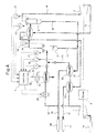
- Fig. 1 is a schematic diagram showing the configuration of the gas treatment equipment according to the first example of the present invention.
- the gas treatment equipment according to the present example includes a compressor 1 for compressing the process gas supplied from the upstream facility, a first separator 2 placed downstream of the compressor 1 to separate the process gas and liquefied process gas, and an expander 3 placed downstream of the first separator 2 to expand the process gas and thus obtain power.
- a first flow path 11 is connected to a process gas inlet of the compressor 1. At an end portion of the first flow path 11, a process gas inlet 10 is placed which is connected to the upstream facility. Between a process gas outlet of the compressor 1 and a process gas inlet of the first separator 2, a second flow path 12 is placed.
- a flow rate control valve (CV 1 ) 20 is placed to regulate the flow rate of the process gas.
- a first heat exchanger 21 for cooling the process gas is placed downstream of the flow rate control valve 20.
- a first temperature indicator (TI 1 ) 23 for measuring the temperature of the process gas is placed downstream of the first heat exchanger 21.
- a refrigerant flow path 45 is connected through which refrigerant gas flows.
- the refrigerant gas passes through the first heat exchanger 21 in order to cool the process gas.
- a refrigerant gas flow rate control valve 22 is placed in the refrigerant flow path 45 to regulate the flow rate of the refrigerant gas flowing through the refrigerant flow path 45. It should be noted that some type of cooling device is needed to appropriately cool the refrigerant gas flowing through the refrigerant flow path 45 but will not be described here because an existing cooling device can be used.
- a branch flow path 13 into which part of the process gas is branched from the second flow path 12 is placed from a point between the compressor 1 and the flow rate control valve 32 to a point between the first temperature indicator 23 and the first separator 2. It should be noted that the second flow path 12 is a main flow path of the process gas.
- a first branch flow path heat exchanger 24 is placed to cool the branched process gas.
- a second branch flow path heat exchanger 25 is placed downstream of the first branch flow path heat exchanger 24.
- a second temperature indicator (TI 2 ) 26 for measuring the temperature of the branched process gas is placed downstream of the second branch flow path heat exchanger 25.
- a third flow path 14 is placed between a process gas outlet of the first separator 2 and a process gas inlet of the expander 4.
- a fifth flow path 16 is connected which passes through the first branch flow path heat exchanger 24.
- a first process gas outlet 17 is placed which is connected to a downstream facility using the treated process gas.
- a fourth flow path 15 is connected which passes through the second branch flow path heat exchanger 25.
- a second process gas outlet 18 is placed which is connected to a downstream facility using the treated liquefied process gas.
- a third temperature indicator (TI 3 ) 27 is placed to measure the temperature of the first separator 2.
- the gas treatment equipment includes a controller 5 which controls the flow rate control valve 20 and the refrigerant gas flow rate control valve 22 based on the temperatures measured by the first to third temperature indicators 23, 26, and 27.
- the controller 5 performs control such that the temperature difference between the process gas flowing through the second flow path 12 and the branched process gas flowing through the branch flow path 13 may be small at the junction thereof.
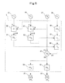
- Fig. 5 is a control block diagram of the gas treatment equipment according to the first example of the present invention.
- the controller 5 of the gas treatment equipment according to this example includes first and second subtractors ( ⁇ 1 and ⁇ 2 ) 50 and 52 each of which performs a subtraction between inputted values, a first function generator (FX 1 ) 51, a second function generator (FX 2 ) 53, a first temperature setter (T SET1 ) 54 which outputs a predetermined set value, first and second adders (+ 1 and + 2 ) 55 and 56 each of which performs an addition of inputted values, a first temperature controller (TC 1 ) 57, a third function generator (FX 3 ) 58, and a fourth function generator (FX 4 ) 59.
- FIG. 9 is a view showing input-output characteristics of the first function generator 51 of the gas treatment equipment according to the first example of the present invention.
- the first function generator 51 of the controller 5 according to this example has input-output characteristics in which the output decreases linearly with the input.
- Fig. 10 is a view showing input-output characteristics of the second function generator 53 of the gas treatment equipment according to the first example of the present invention.
- the second function generator 53 of the controller 5 according to this example has input-output characteristics in which the output decreases linearly with the input. It should be noted that in this example, the output-to-input ratio of the second function generator 53 is set smaller than that of the first function generator 51.
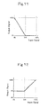
- Fig. 11 is a view showing input-output characteristics of the third function generator 58 of the gas treatment equipment according to the first example of the present invention.
- input-output characteristics of the third function generator 58 of the controller 5 according to this example are set as follows with the input being represented in the range of 0% to 100% in accordance with the value of an inputted signal: in the region in which the input is 0% to 50%, the output decreases linearly; in the region in which the input is 50% to 100%, the output is set to 0%.
- Fig. 12 is a view showing input-output characteristics of the fourth function generator 59 of the gas treatment equipment according to the first example of the present invention.
- input-output characteristics of the fourth function generator 59 of the controller 5 according to this example are set as follows with the input being represented in the range of 0% to 100% in accordance with the value of an inputted signal: in the region in which the input is 0% to 50%, the output is set to a predetermined value X%; in the region in which the input is 50% to 100%, the output increases linearly.
- the first subtractor 50 receives signals from the first and second temperature indicators 23 and 26, and outputs to the first function generator 51 the value obtained by subtracting the signal value of the first temperature indicator 23 from the signal value of the second temperature indicator 26.
- the second subtractor 52 receives signals from the second and third temperature indicators 26 and 27, and outputs to the second function generator 53 the value obtained by subtracting the signal value of the third temperature indicator 27 from the signal value of the second temperature indicator 26.
- the first adder 55 receives signals from the second function generator 53 and the first temperature setter 54, and outputs to the second adder 56 the value obtained by adding the signal value of the second function generator 53 and the signal value of the first temperature setter 54.
- the second adder 56 receives signals from the first function generator 51 and the first adder 55, and outputs to the first temperature controller 57 the value obtained by adding the signal value of the first function generator 51 and the signal value of the first adder 55.
- the first temperature controller 57 receives signals from the third temperature indicator 27 and the second adder 56, and outputs a temperature control signal to the third and fourth function generators 58 and 59 based on the signal values of the third temperature indicator 27 and the second adder 56.
- the third function generator 58 receives the temperature control signal from the first temperature controller 57, and produces an output in accordance with the value of the received temperature control signal. The output from the third function generator 58 is used to control the flow rate control valve 20.
- the fourth function generator 59 receives the temperature control signal from the first temperature controller 57, and produces an output in accordance with the value of the received temperature control signal. The output from the fourth function generator 59 is used to control the refrigerant gas flow rate control valve 22.
- the branched process gas flowing through the branch flow path 13 is cooled by the first and second branch flow path heat exchangers 24 and 25. This reduces the load on a cooling device for cooling the refrigerant gas which passes through the first heat exchanger 21 in order to cool the process gas flowing through the second flow path 12. Accordingly, gas temperature control can be performed efficiently without being affected by the load.
- Fig. 2 is a schematic diagram showing the configuration of the gas treatment equipment according to the second example of the present invention.
- the gas treatment equipment according to this example has approximately the same configuration as the gas treatment equipment according to the first example, but further includes a first pressure indicator (PI 1 ) 28 for measuring the pressure in the first separator 2.
- PI 1 first pressure indicator
- Fig. 6 is a control block diagram of the gas treatment equipment according to the second example of the present invention.
- the controller 5 of the gas treatment equipment according to this example has approximately the same configuration as the controller 5 of the gas treatment equipment according to the first example, but includes a fifth function generator (FX 5 ) 60 instead of the first temperature setter 54.
- FX 5 fifth function generator
- FIG. 13 is a view showing the input-output characteristics of the fifth function generator 60 of the gas treatment equipment according to the second example of the present invention.
- the fifth function generator 60 of the controller 5 has input-output characteristics represented by a characteristic curve extending along and below the curve which represents the relationship between the input and the output when the process gas reaches saturation and which is indicated by arrow a in Fig. 13 .
- the fifth function generator 60 receives the signal from the first pressure indicator 28, and outputs a signal to the first adder 55 in accordance with the signal value of the first pressure indicator 28.
- the gas treatment equipment according to this example can perform control such that the temperature difference between the process gas flowing through the second flow path 12 and the branched process gas flowing through the branch flow path 13 may be further smaller at the junction thereof, because the actual pressure in the first separator 2 is used. Accordingly, gas temperature control can be performed more efficiently without being affected by the load.
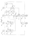
- Fig. 3 is a schematic diagram showing the configuration of the gas treatment equipment according to the third example of the present invention.
- the gas treatment equipment according to this example has approximately the same configuration as the gas treatment equipment according to the first example, but further includes a second heat exchanger 30, a second separator 6, and a fourth temperature indicator (TI 4 ) 29.
- the second heat exchanger 30 and the second separator 6 are placed between the first separator 2 and the expander 3.
- the fourth temperature indicator 29 is placed to measure the temperature of the process gas in the second separator 6.
- a sixth flow path 40 is placed between the process gas outlet of the first separator 2 and a process gas inlet of the second separator 6.
- the second heat exchanger 30 is placed to cool the process gas.
- the third flow path 14 is placed between a process gas outlet of the second separator 6 and the process gas inlet of the expander 3.
- the fifth flow path 16 is connected which passes through the second heat exchanger 30 and then through the first branch flow path heat exchanger 24.
- a seventh flow path 41 is connected to a liquefied process gas outlet of the second separator 6.
- the seventh flow path 41 is connected to the fourth flow path 15.
- Fig. 7 is a control block diagram of the gas treatment equipment according to the third example of the present invention.
- the controller 5 of the gas treatment equipment according to this example has approximately the same configuration as the controller 5 of the gas treatment equipment according to the first example, but further includes a second temperature setter (T SET2 ) 70 which outputs a predetermined set value, a second temperature controller (TC 2 ) 71, and a minimum selector (MIN) 72.
- T SET2 second temperature setter
- TC 2 second temperature controller
- MIN minimum selector
- the second temperature controller 71 receives signals from the fourth temperature indicator 29 and the second temperature setter 70, and outputs a signal to the minimum selector 72 in accordance with the signal value of the fourth temperature indicator 29 and the signal value of the second temperature setter 70.
- the minimum selector 72 receives temperature control signals from the first and second temperature controllers 57 and 71, compares the values of the temperature control signals from the first and second temperature controllers 57 and 71, and outputs the smaller one of these signals to the third and fourth function generators 58 and 59.
- the gas treatment equipment according to this example can perform gas temperature control more efficiently without being affected by the load, because of the inclusion of the first and second separators 2 and 6. It should be noted that though the first and second separators 2 and 6 are installed in this example, more separators may be installed.
- Fig. 4 is a schematic diagram showing the configuration of the gas treatment equipment according to the fourth example of the present invention.
- the gas treatment equipment according to this example has approximately the same configuration as the gas treatment equipment according to the third example, but further includes the first pressure indicator (PI 1 ) 28 for measuring the pressure in the first separator 2 and a second pressure indicator (PI 2 ) 31 for measuring the pressure in the second separator 6.
- PI 1 first pressure indicator
- PI 2 second pressure indicator
- Fig. 8 is a control block diagram of the gas treatment equipment according to the fourth example of the present invention.
- the controller 5 of the gas treatment equipment according to this example has approximately the same configuration as the controller 5 of the gas treatment equipment according to the third example, but includes the fifth function generator 60 instead of the first temperature setter 54, and a sixth function generator (FX 6 ) 80 instead of the second temperature setter 70.
- FX 6 sixth function generator
- FIG. 14 is a view showing the input-output characteristics of the sixth function generator 80 of the gas treatment equipment according to the fourth example of the present invention.
- the sixth function generator 80 of the controller 5 has input-output characteristics represented by a characteristic curve extending along and below the curve which represents the relationship between the input and the output when the process gas reaches saturation and which is indicated by arrow b in Fig. 14 .
- the output-to-input radio of the sixth function generator 80 is set smaller than that of the fifth function generator 60.
- the sixth function generator 80 receives the signal from the second pressure indicator 31 and outputs a signal to the second temperature controller 71 in accordance with the signal value of the second pressure indicator 31.
- the gas treatment equipment according to this example can perform control such that the temperature difference between the process gas flowing through the second flow path 12 and the branched process gas flowing through the branch flow path 13 may be further smaller at the junction thereof, because the actual pressures in the first and second separators 2 and 6 are used. Accordingly, gas temperature control can be performed more efficiently without being affected by the load even in the case where the first and second separators 2 and 6 are installed.
- the present invention can be applied to, for example, gas treatment equipment which includes a freezing compressor.
Landscapes
- Engineering & Computer Science (AREA)
- Physics & Mathematics (AREA)
- Mechanical Engineering (AREA)
- Thermal Sciences (AREA)
- General Engineering & Computer Science (AREA)
- Separation By Low-Temperature Treatments (AREA)
- Separation Of Gases By Adsorption (AREA)
Abstract
Description
- The present invention relates to gas treatment equipment.
- As a system configuration of gas treatment equipment including a freezing compressor, a configuration has heretofore been known in which a compressor, a cooler, a separator, and a heat exchanger are connected in series and in which the temperature of the separator is controlled by the cooler. Such a configuration is disclosed in, for example, the following
Patent Literature 1 <in particular, seeFig. 1 of the followingPatent Literature 1>. In other words, in the conventional gas treatment equipment disclosed in the followingPatent Literature 1, gas compressed by the compressor is cooled only by the cooler. -
Patent Document 1US Patent No. 5791160 - However, the above-described conventional gas treatment equipment has a problem that the overall efficiency of the gas treatment equipment is low, because the temperature difference between an inlet and an outlet of the cooler is large when the load thereon is heavy.
In view of the above, an object of the present invention is to provide gas treatment equipment capable of performing efficient gas temperature control without being affected by the load. - Gas treatment equipment according to a first aspect of the present invention which addresses the above-described problem includes: a compressor which compresses process gas; a heat exchanger which is disposed downstream of the compressor and which cools the process gas in a main flow path of the process gas; a separator which is disposed downstream of the heat exchanger and which separates the process gas and liquefied process gas; an expander which is disposed downstream of the separator and which expands the process gas to obtain power; a refrigerant gas flow rate control valve which regulates a flow rate of refrigerant gas passing through the heat exchanger and thereby cooling the process gas; a branch flow path into which part of the process gas is branched from the main flow path so as not to pass through the heat exchanger; first and second branch flow path heat exchangers which are disposed in the branch flow path and which cool the branched process gas; a first outlet flow path which is connected to a liquefied process gas outlet of the separator and which passes through the first branch flow path heat exchanger; a second outlet flow path which is connected to a process gas outlet of the expander and which passes through the second branch flow path heat exchanger; a first temperature indicator which is disposed between the heat exchanger and a junction of the main flow path and the branch flow path, and which measures a temperature of the process gas; a second temperature indicator which is disposed between the second branch flow path heat exchanger and the junction of the main flow path and the branch flow path, and which measures a temperature of the branched process gas; a third temperature indicator which is disposed in the separator and which measures a temperature of the process gas; a flow rate control valve which is disposed between the heat exchanger and a branching point between the main flow path and the branch flow path, and which regulates a flow rate of the process gas; and control means which controls at least one of the flow rate control valve and the refrigerant gas flow rate control valve on the basis of the temperatures measured by the first to third temperature indicators.
- Gas treatment equipment according to a second aspect of the present invention which addresses the above-described problem further includes a first pressure indicator which is disposed in the separator and which measures a pressure in the gas treatment equipment according to the first aspect. In the gas treatment equipment, the control means controls at least one of the flow rate control valve and the refrigerant gas flow rate control valve on the basis of the temperatures measured by the first to third temperature indicators and the pressure measured by the first pressure indicator.
- Gas treatment equipment according to a third aspect of the present invention which addresses the above-described problem further includes a second heat exchanger and a second separator which are disposed between the separator and the expander, and a fourth temperature indicator which is disposed in the second separator and which measures a temperature of the process gas in the gas treatment equipment according to the first aspect. In the gas treatment equipment, the control means controls at least one of the flow rate control valve and the refrigerant gas flow rate control valve on the basis of the temperatures measured by the first to fourth temperature indicators.
- Gas treatment equipment according to a third aspect of the present invention which addresses the above-described problem further includes a first pressure indicator which is disposed in the separator and which measures a pressure, and a second pressure indicator which is disposed in the second separator and which measures a pressure in the gas treatment equipment according to the third aspect. In the gas treatment equipment, the control means controls at least one of the flow rate control valve and the refrigerant gas flow rate control valve on the basis of the temperatures measured by the first to fourth temperature indicators and the pressures measured by the first and second pressure indicators.
- The present invention makes it possible to provide gas treatment equipment capable of performing efficient gas temperature control without being affected by the load.
-
- [
Fig. 1] Fig. 1 is a schematic diagram showing the configuration of gas treatment equipment according to a first example of the present invention. - [
Fig. 2] Fig. 2 is a schematic diagram showing the configuration of gas treatment equipment according to a second example of the present invention. - [
Fig. 3] Fig. 3 is a schematic diagram showing the configuration of gas treatment equipment according to a third example of the present invention. - [
Fig. 4] Fig. 4 is a schematic diagram showing the configuration of gas treatment equipment according to a fourth example of the present invention. - [
Fig. 5] Fig. 5 is a control block diagram of the gas treatment equipment according to the first example of the present invention. - [
Fig. 6] Fig. 6 is a control block diagram of the gas treatment equipment according to the second example of the present invention. - [
Fig. 7] Fig. 7 is a control block diagram of the gas treatment equipment according to the third example of the present invention. - [
Fig. 8] Fig. 8 is a control block diagram of the gas treatment equipment according to the fourth example of the present invention. - [
Fig. 9] Fig. 9 is a view showing input-output characteristics of a first function generator of the gas treatment equipment according to the first example of the present invention. - [
Fig. 10] Fig. 10 is a view showing input-output characteristics of a second function generator of the gas treatment equipment according to the first example of the present invention. - [
Fig. 11] Fig. 11 is a view showing input-output characteristics of a third function generator of the gas treatment equipment according to the first example of the present invention. - [
Fig. 12] Fig. 12 is a view showing input-output characteristics of a fourth function generator of the gas treatment equipment according to the first example of the present invention. - [
Fig. 13] Fig. 13 is a view showing input-output characteristics of a fifth function generator of the gas treatment equipment according to the second example of the present invention. - [
Fig. 14] Fig. 14 is a view showing input-output characteristics of a sixth function generator of the gas treatment equipment according to the fourth example of the present invention. - Hereinafter, modes for implementing gas treatment equipment according to the present invention will be described with reference to the accompanying drawings.
- Hereinafter, a first example of gas treatment equipment according to the present invention will be described.
First, the configuration of the gas treatment equipment according to the first example of the present invention will be described.
It should be noted that a facility serving as a supply source of process gas is located upstream of the gas treatment equipment according to this example, and that a facility using the treated process gas is located downstream thereof. However, they will not be described here. -
Fig. 1 is a schematic diagram showing the configuration of the gas treatment equipment according to the first example of the present invention.
As shown inFig. 1 , the gas treatment equipment according to the present example includes acompressor 1 for compressing the process gas supplied from the upstream facility, afirst separator 2 placed downstream of thecompressor 1 to separate the process gas and liquefied process gas, and anexpander 3 placed downstream of thefirst separator 2 to expand the process gas and thus obtain power. - A
first flow path 11 is connected to a process gas inlet of thecompressor 1. At an end portion of thefirst flow path 11, aprocess gas inlet 10 is placed which is connected to the upstream facility. Between a process gas outlet of thecompressor 1 and a process gas inlet of thefirst separator 2, asecond flow path 12 is placed. - In the
second flow path 12, a flow rate control valve (CV1) 20 is placed to regulate the flow rate of the process gas. In thesecond flow path 12, afirst heat exchanger 21 for cooling the process gas is placed downstream of the flowrate control valve 20. In thesecond flow path 12, a first temperature indicator (TI1) 23 for measuring the temperature of the process gas is placed downstream of thefirst heat exchanger 21. - To the
first heat exchanger 21, arefrigerant flow path 45 is connected through which refrigerant gas flows. The refrigerant gas passes through thefirst heat exchanger 21 in order to cool the process gas. In therefrigerant flow path 45, a refrigerant gas flowrate control valve 22 is placed to regulate the flow rate of the refrigerant gas flowing through therefrigerant flow path 45. It should be noted that some type of cooling device is needed to appropriately cool the refrigerant gas flowing through therefrigerant flow path 45 but will not be described here because an existing cooling device can be used. - A
branch flow path 13 into which part of the process gas is branched from thesecond flow path 12 is placed from a point between thecompressor 1 and the flow rate control valve 32 to a point between thefirst temperature indicator 23 and thefirst separator 2. It should be noted that thesecond flow path 12 is a main flow path of the process gas. - In the
branch flow path 13, a first branch flowpath heat exchanger 24 is placed to cool the branched process gas. In thebranch flow path 13, a second branch flowpath heat exchanger 25 is placed downstream of the first branch flowpath heat exchanger 24. In thebranch flow path 13, a second temperature indicator (TI2) 26 for measuring the temperature of the branched process gas is placed downstream of the second branch flowpath heat exchanger 25. - Between a process gas outlet of the
first separator 2 and a process gas inlet of theexpander 4, athird flow path 14 is placed. To a process gas outlet of theexpander 3, afifth flow path 16 is connected which passes through the first branch flowpath heat exchanger 24. At an end portion of thefifth flow path 16, a firstprocess gas outlet 17 is placed which is connected to a downstream facility using the treated process gas. - To a liquefied process gas outlet of the
first separator 2, afourth flow path 15 is connected which passes through the second branch flowpath heat exchanger 25. At an end portion of thefourth flow path 15, a secondprocess gas outlet 18 is placed which is connected to a downstream facility using the treated liquefied process gas. In thefirst separator 2, a third temperature indicator (TI3) 27 is placed to measure the temperature of thefirst separator 2. - The gas treatment equipment according to this example includes a
controller 5 which controls the flowrate control valve 20 and the refrigerant gas flowrate control valve 22 based on the temperatures measured by the first tothird temperature indicators controller 5 performs control such that the temperature difference between the process gas flowing through thesecond flow path 12 and the branched process gas flowing through thebranch flow path 13 may be small at the junction thereof. - Next, a method of controlling the gas treatment equipment according to the first example will be described.
Fig. 5 is a control block diagram of the gas treatment equipment according to the first example of the present invention.
As shown inFig. 5 , thecontroller 5 of the gas treatment equipment according to this example includes first and second subtractors (Δ1 and Δ2) 50 and 52 each of which performs a subtraction between inputted values, a first function generator (FX1) 51, a second function generator (FX2) 53, a first temperature setter (TSET1) 54 which outputs a predetermined set value, first and second adders (+1 and +2) 55 and 56 each of which performs an addition of inputted values, a first temperature controller (TC1) 57, a third function generator (FX3) 58, and a fourth function generator (FX4) 59. - Here, input-output characteristics of the first to
fourth function generators
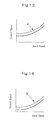
Fig. 9 is a view showing input-output characteristics of thefirst function generator 51 of the gas treatment equipment according to the first example of the present invention.
As shown inFig. 9 , thefirst function generator 51 of thecontroller 5 according to this example has input-output characteristics in which the output decreases linearly with the input. -
Fig. 10 is a view showing input-output characteristics of thesecond function generator 53 of the gas treatment equipment according to the first example of the present invention.
As shown inFig. 10 , thesecond function generator 53 of thecontroller 5 according to this example has input-output characteristics in which the output decreases linearly with the input. It should be noted that in this example, the output-to-input ratio of thesecond function generator 53 is set smaller than that of thefirst function generator 51. -
Fig. 11 is a view showing input-output characteristics of thethird function generator 58 of the gas treatment equipment according to the first example of the present invention.
As shown inFig. 11 , input-output characteristics of thethird function generator 58 of thecontroller 5 according to this example are set as follows with the input being represented in the range of 0% to 100% in accordance with the value of an inputted signal: in the region in which the input is 0% to 50%, the output decreases linearly; in the region in which the input is 50% to 100%, the output is set to 0%. -
Fig. 12 is a view showing input-output characteristics of thefourth function generator 59 of the gas treatment equipment according to the first example of the present invention.
As shown inFig. 12 , input-output characteristics of thefourth function generator 59 of thecontroller 5 according to this example are set as follows with the input being represented in the range of 0% to 100% in accordance with the value of an inputted signal: in the region in which the input is 0% to 50%, the output is set to a predetermined value X%; in the region in which the input is 50% to 100%, the output increases linearly. - In the
controller 5 of the gas treatment equipment according to this example, thefirst subtractor 50 receives signals from the first andsecond temperature indicators first function generator 51 the value obtained by subtracting the signal value of thefirst temperature indicator 23 from the signal value of thesecond temperature indicator 26. - Further, in the
controller 5, thesecond subtractor 52 receives signals from the second andthird temperature indicators second function generator 53 the value obtained by subtracting the signal value of thethird temperature indicator 27 from the signal value of thesecond temperature indicator 26. - Moreover, in the
controller 5, thefirst adder 55 receives signals from thesecond function generator 53 and thefirst temperature setter 54, and outputs to thesecond adder 56 the value obtained by adding the signal value of thesecond function generator 53 and the signal value of thefirst temperature setter 54. - Furthermore, in the
controller 5, thesecond adder 56 receives signals from thefirst function generator 51 and thefirst adder 55, and outputs to thefirst temperature controller 57 the value obtained by adding the signal value of thefirst function generator 51 and the signal value of thefirst adder 55. - Also, in the
controller 5, thefirst temperature controller 57 receives signals from thethird temperature indicator 27 and thesecond adder 56, and outputs a temperature control signal to the third andfourth function generators third temperature indicator 27 and thesecond adder 56. - Further, in the
controller 5, thethird function generator 58 receives the temperature control signal from thefirst temperature controller 57, and produces an output in accordance with the value of the received temperature control signal. The output from thethird function generator 58 is used to control the flowrate control valve 20. - Moreover, in the
controller 5, thefourth function generator 59 receives the temperature control signal from thefirst temperature controller 57, and produces an output in accordance with the value of the received temperature control signal. The output from thefourth function generator 59 is used to control the refrigerant gas flowrate control valve 22. - As described above, in the gas treatment equipment of this example, the branched process gas flowing through the
branch flow path 13 is cooled by the first and second branch flowpath heat exchangers first heat exchanger 21 in order to cool the process gas flowing through thesecond flow path 12. Accordingly, gas temperature control can be performed efficiently without being affected by the load. - Hereinafter, a second example of gas treatment equipment according to the present invention will be described.
First, the configuration of the gas treatment equipment according to the second example of the present invention will be described.
Fig. 2 is a schematic diagram showing the configuration of the gas treatment equipment according to the second example of the present invention.
As shown inFig. 2 , the gas treatment equipment according to this example has approximately the same configuration as the gas treatment equipment according to the first example, but further includes a first pressure indicator (PI1) 28 for measuring the pressure in thefirst separator 2. - Next, a method of controlling the gas treatment equipment according to the second example of the present invention will be described.
Fig. 6 is a control block diagram of the gas treatment equipment according to the second example of the present invention.
As shown inFig. 6 , thecontroller 5 of the gas treatment equipment according to this example has approximately the same configuration as thecontroller 5 of the gas treatment equipment according to the first example, but includes a fifth function generator (FX5) 60 instead of thefirst temperature setter 54. - Here, input-output characteristics of the
fifth function generator 60 will be described.
Fig. 13 is a view showing the input-output characteristics of thefifth function generator 60 of the gas treatment equipment according to the second example of the present invention.
As shown inFig. 13 , thefifth function generator 60 of thecontroller 5 according to this example has input-output characteristics represented by a characteristic curve extending along and below the curve which represents the relationship between the input and the output when the process gas reaches saturation and which is indicated by arrow a inFig. 13 . - Unlike in the
controller 5 of the gas treatment equipment according to the first example, in thecontroller 5 of the gas treatment equipment according to this example, thefifth function generator 60 receives the signal from thefirst pressure indicator 28, and outputs a signal to thefirst adder 55 in accordance with the signal value of thefirst pressure indicator 28. - Thus, in addition to effects of the first example, the gas treatment equipment according to this example can perform control such that the temperature difference between the process gas flowing through the
second flow path 12 and the branched process gas flowing through thebranch flow path 13 may be further smaller at the junction thereof, because the actual pressure in thefirst separator 2 is used. Accordingly, gas temperature control can be performed more efficiently without being affected by the load. - Hereinafter, a third example of gas treatment equipment according to the present invention will be described.
First, the configuration of the gas treatment equipment according to the third example of the present invention will be described.
Fig. 3 is a schematic diagram showing the configuration of the gas treatment equipment according to the third example of the present invention.
As shown inFig. 3 , the gas treatment equipment according to this example has approximately the same configuration as the gas treatment equipment according to the first example, but further includes asecond heat exchanger 30, a second separator 6, and a fourth temperature indicator (TI4) 29. Thesecond heat exchanger 30 and the second separator 6 are placed between thefirst separator 2 and theexpander 3. Thefourth temperature indicator 29 is placed to measure the temperature of the process gas in the second separator 6. - In the gas treatment equipment according to this example, a
sixth flow path 40 is placed between the process gas outlet of thefirst separator 2 and a process gas inlet of the second separator 6. In thesixth flow path 40, thesecond heat exchanger 30 is placed to cool the process gas. Thethird flow path 14 is placed between a process gas outlet of the second separator 6 and the process gas inlet of theexpander 3. - To the process gas outlet of the
expander 3, thefifth flow path 16 is connected which passes through thesecond heat exchanger 30 and then through the first branch flowpath heat exchanger 24. To a liquefied process gas outlet of the second separator 6, aseventh flow path 41 is connected. Theseventh flow path 41 is connected to thefourth flow path 15. - Next, a method of controlling the gas treatment equipment according to the third example of the present invention will be described.
Fig. 7 is a control block diagram of the gas treatment equipment according to the third example of the present invention.
As shown inFig. 7 , thecontroller 5 of the gas treatment equipment according to this example has approximately the same configuration as thecontroller 5 of the gas treatment equipment according to the first example, but further includes a second temperature setter (TSET2) 70 which outputs a predetermined set value, a second temperature controller (TC2) 71, and a minimum selector (MIN) 72. - Unlike in the
controller 5 of the gas treatment equipment according to the first example, in thecontroller 5 of the gas treatment equipment according to this example, thesecond temperature controller 71 receives signals from thefourth temperature indicator 29 and thesecond temperature setter 70, and outputs a signal to theminimum selector 72 in accordance with the signal value of thefourth temperature indicator 29 and the signal value of thesecond temperature setter 70. - Further, in the
controller 5, theminimum selector 72 receives temperature control signals from the first andsecond temperature controllers second temperature controllers fourth function generators - Thus, in addition to effects of the first example, the gas treatment equipment according to this example can perform gas temperature control more efficiently without being affected by the load, because of the inclusion of the first and
second separators 2 and 6. It should be noted that though the first andsecond separators 2 and 6 are installed in this example, more separators may be installed. - Hereinafter, a fourth example of gas treatment equipment according to the present invention will be described.
First, the configuration of the gas treatment equipment according to the fourth example of the present invention will be described.
Fig. 4 is a schematic diagram showing the configuration of the gas treatment equipment according to the fourth example of the present invention.
As shown inFig. 4 , the gas treatment equipment according to this example has approximately the same configuration as the gas treatment equipment according to the third example, but further includes the first pressure indicator (PI1) 28 for measuring the pressure in thefirst separator 2 and a second pressure indicator (PI2) 31 for measuring the pressure in the second separator 6. - Next, a method of controlling the gas treatment equipment according to the fourth example of the present invention will be described.
Fig. 8 is a control block diagram of the gas treatment equipment according to the fourth example of the present invention.
As shown inFig. 8 , thecontroller 5 of the gas treatment equipment according to this example has approximately the same configuration as thecontroller 5 of the gas treatment equipment according to the third example, but includes thefifth function generator 60 instead of thefirst temperature setter 54, and a sixth function generator (FX6) 80 instead of thesecond temperature setter 70. - Here, input-output characteristics of the
sixth function generator 80 will be described. It should be noted that input-output characteristics of thefifth function generator 60 are the same as those described in the second example.
Fig. 14 is a view showing the input-output characteristics of thesixth function generator 80 of the gas treatment equipment according to the fourth example of the present invention.
As shown inFig. 14 , thesixth function generator 80 of thecontroller 5 according to this example has input-output characteristics represented by a characteristic curve extending along and below the curve which represents the relationship between the input and the output when the process gas reaches saturation and which is indicated by arrow b inFig. 14 . It should be noted that in this example, the output-to-input radio of thesixth function generator 80 is set smaller than that of thefifth function generator 60. - Unlike in the
controller 5 of the gas treatment equipment according to the third example, in thecontroller 5 of the gas treatment equipment according to this example, thesixth function generator 80 receives the signal from thesecond pressure indicator 31 and outputs a signal to thesecond temperature controller 71 in accordance with the signal value of thesecond pressure indicator 31. - Thus, in addition to effects of the third example, the gas treatment equipment according to this example can perform control such that the temperature difference between the process gas flowing through the
second flow path 12 and the branched process gas flowing through thebranch flow path 13 may be further smaller at the junction thereof, because the actual pressures in the first andsecond separators 2 and 6 are used. Accordingly, gas temperature control can be performed more efficiently without being affected by the load even in the case where the first andsecond separators 2 and 6 are installed. - The present invention can be applied to, for example, gas treatment equipment which includes a freezing compressor.
-
- 1
- COMPRESSOR
- 2
- FIRST SEPARATOR
- 3
- EXPANDER
- 4
- DRIVER
- 5
- CONTROLLER
- 6
- SECOND SEPARATOR
- 10
- PROCESS GAS INLET
- 11
- FIRST FLOW PATH
- 12
- SECOND FLOW PATH
- 13
- BRANCH FLOW PATH
- 14
- THIRD FLOW PATH
- 15
- FOURTH FLOW PATH
- 16
- FIFTH FLOW PATH
- 17
- FIRST PROCESS GAS OUTLET
- 18
- SECOND PROCESS GAS OUTLET
- 20
- FLOW RATE CONTROL VALVE (CV1)
- 21
- FIRST HEAT EXCHANGER
- 22
- REFRIGERANT GAS FLOW RATE CONTROL VALVE (CV2)
- 23
- FIRST TEMPERATURE INDICATOR (TI1)
- 24
- FIRST BRANCH FLOW PATH HEAT EXCHANGER
- 25
- SECOND BRANCH FLOW PATH HEAT EXCHANGER
- 26
- SECOND TEMPERATURE INDICATOR (TI2)
- 27
- THIRD TEMPERATURE INDICATOR (TI3)
- 28
- FIRST PRESSURE INDICATOR (PI1)
- 29
- THIRD TEMPERATURE INDICATOR (TI4)
- 30
- SECOND HEAT EXCHANGER
- 31
- SECOND PRESSURE INDICATOR (PI2)
- 40
- SIXTH FLOW PATH
- 41
- SEVENTH FLOW PATH
- 45
- REFRIGERANT FLOW PATH
- 50
- FIRST SUBTRACTOR (Δ1)
- 51
- FIRST FUNCTION GENERATOR (FX1)
- 52
- SECOND SUBTRACTOR (Δ2)
- 53
- SECOND FUNCTION GENERATOR (FX2)
- 54
- FIRST TEMPERATURE SETTER (TSET1)
- 55
- FIRST ADDER (+1)
- 56
- SECOND ADDER (+2)
- 57
- FIRST TEMPERATURE CONTROLLER (TC1)
- 58
- THIRD FUNCTION GENERATOR (FX3)
- 59
- FOURTH FUNCTION GENERATOR (FX4)
- 60
- FIFTH FUNCTION GENERATOR (FX5)
- 70
- SECOND TEMPERATURE SETTER (TSET2)
- 71
- SECOND TEMPERATURE CONTROLLER (TC2)
- 72
- MINIMUM SELECTOR (MIN)
- 80
- SIXTH FUNCTION GENERATOR (FX6)
Claims (4)
- Gas treatment equipment comprising:a compressor which compresses process gas;a heat exchanger which is disposed downstream of the compressor and which cools the process gas in a main flow path of the process gas;a separator which is disposed downstream of the heat exchanger and which separates the process gas and liquefied process gas;an expander which is disposed downstream of the separator and which expands the process gas to obtain power;a refrigerant gas flow rate control valve which regulates a flow rate of refrigerant gas passing through the heat exchanger and thereby cooling the process gas;a branch flow path into which part of the process gas is branched from the main flow path so as not to pass through the heat exchanger;first and second branch flow path heat exchangers which are disposed in the branch flow path and which cool the branched process gas;a first outlet flow path which is connected to a liquefied process gas outlet of the separator and which passes through the first branch flow path heat exchanger;a second outlet flow path which is connected to a process gas outlet of the expander and which passes through the second branch flow path heat exchanger;a first temperature indicator which is disposed between the heat exchanger and a junction of the main flow path and the branch flow path, and which measures a temperature of the process gas;a second temperature indicator which is disposed between the second branch flow path heat exchanger and the junction of the main flow path and the branch flow path, and which measures a temperature of the branched process gas;a third temperature indicator which is disposed in the separator and which measures a temperature of the process gas;a flow rate control valve which is disposed between the heat exchanger and a branching point between the main flow path and the branch flow path, and which regulates a flow rate of the process gas; andcontrol means which controls at least one of the flow rate control valve and the refrigerant gas flow rate control valve on the basis of the temperatures measured by the first to third temperature indicators.
- The gas treatment equipment according to claim 1, further comprising a first pressure indicator which is disposed in the separator and which measures a pressure,wherein the control means controls at least one of the flow rate control valve and the refrigerant gas flow rate control valve on the basis of the temperatures measured by the first to third temperature indicators and the pressure measured by the first pressure indicator.
- The gas treatment equipment according to claim 1, further comprising:a second heat exchanger and a second separator which are disposed between the separator and the expander; anda fourth temperature indicator which is disposed in the second separator and which measures a temperature of the process gas,wherein the control means controls at least one of the flow rate control valve and the refrigerant gas flow rate control valve on the basis of the temperatures measured by the first to fourth temperature indicators.
- The gas treatment equipment according to claim 3, further comprising:a first pressure indicator which is disposed in the separator and which measures a pressure; anda second pressure indicator which is disposed in the second separator and which measures a pressure,wherein the control means controls at least one of the flow rate control valve and the refrigerant gas flow rate control valve on the basis of the temperatures measured by the first to fourth temperature indicators and the pressures measured by the first and second pressure indicators.
Applications Claiming Priority (2)
| Application Number | Priority Date | Filing Date | Title |
|---|---|---|---|
| JP2009227019A JP5191969B2 (en) | 2009-09-30 | 2009-09-30 | Gas processing equipment |
| PCT/JP2010/065468 WO2011040199A1 (en) | 2009-09-30 | 2010-09-09 | Gas treatment device |
Publications (2)
| Publication Number | Publication Date |
|---|---|
| EP2485000A1 true EP2485000A1 (en) | 2012-08-08 |
| EP2485000A4 EP2485000A4 (en) | 2018-01-03 |
Family
ID=43826027
Family Applications (1)
| Application Number | Title | Priority Date | Filing Date |
|---|---|---|---|
| EP10820319.1A Withdrawn EP2485000A4 (en) | 2009-09-30 | 2010-09-09 | Gas treatment device |
Country Status (6)
| Country | Link |
|---|---|
| US (1) | US8899076B2 (en) |
| EP (1) | EP2485000A4 (en) |
| JP (1) | JP5191969B2 (en) |
| CN (1) | CN102422109B (en) |
| RU (1) | RU2493480C2 (en) |
| WO (1) | WO2011040199A1 (en) |
Families Citing this family (3)
| Publication number | Priority date | Publication date | Assignee | Title |
|---|---|---|---|---|
| CN104396469A (en) * | 2014-12-12 | 2015-03-11 | 苏州青青生态种植园 | Dust removal equipment applied to straw chopping production line |
| MY193428A (en) | 2019-03-14 | 2022-10-12 | Ngltech Sdn Bhd | System for recovering natural gas liquid from low pressure source at low temperatures |
| JP2023003800A (en) * | 2021-06-24 | 2023-01-17 | サンデン株式会社 | Heat exchanger |
Family Cites Families (29)
| Publication number | Priority date | Publication date | Assignee | Title |
|---|---|---|---|---|
| US4356014A (en) * | 1979-04-04 | 1982-10-26 | Petrochem Consultants, Inc. | Cryogenic recovery of liquids from refinery off-gases |
| US4609390A (en) * | 1984-05-14 | 1986-09-02 | Wilson Richard A | Process and apparatus for separating hydrocarbon gas into a residue gas fraction and a product fraction |
| RU2028567C1 (en) | 1989-07-11 | 1995-02-09 | Научно-исследовательский и проектный институт по переработке газа | Method of separation of gas hydrocarbon mixture |
| US5024061A (en) * | 1989-12-12 | 1991-06-18 | Terrestrial Engineering Corporation | Recovery processing and storage unit |
| US4936888A (en) * | 1989-12-21 | 1990-06-26 | Phillips Petroleum Company | Nitrogen rejection unit |
| US5375422A (en) * | 1991-04-09 | 1994-12-27 | Butts; Rayburn C. | High efficiency nitrogen rejection unit |
| CN1067114A (en) * | 1991-05-21 | 1992-12-16 | 北京市西城区新开通用试验厂 | A kind of separating unit for liquefying petroleum gas |
| US5493200A (en) * | 1993-05-12 | 1996-02-20 | Sundstrand Corporation | Control for a brushless generator |
| US5426952A (en) * | 1994-03-03 | 1995-06-27 | General Electric Company | Refrigerant flow rate control based on evaporator exit dryness |
| US5499531A (en) * | 1995-03-17 | 1996-03-19 | The Mitre Corporation | System and method for determining volatile constituents, vapor pressure and vapor emissions of liquids |
| RU3811U1 (en) | 1996-01-16 | 1997-03-16 | Акционерное общество открытого типа "Научно-исследовательский и проектный институт по переработке газа" | INSTALLATION OF PROCESSING OF HYDROCARBON RAW MATERIALS |
| US5791160A (en) * | 1997-07-24 | 1998-08-11 | Air Products And Chemicals, Inc. | Method and apparatus for regulatory control of production and temperature in a mixed refrigerant liquefied natural gas facility |
| US6626635B1 (en) * | 1998-09-30 | 2003-09-30 | General Electric Company | System for controlling clearance between blade tips and a surrounding casing in rotating machinery |
| US6257070B1 (en) * | 1999-01-13 | 2001-07-10 | Intevep, S.A. | Method and apparatus for determining real time liquid and gas phase flow rates |
| US6332336B1 (en) * | 1999-02-26 | 2001-12-25 | Compressor Controls Corporation | Method and apparatus for maximizing the productivity of a natural gas liquids production plant |
| US6453698B2 (en) * | 2000-04-13 | 2002-09-24 | Ipsi Llc | Flexible reflux process for high NGL recovery |
| MY128820A (en) * | 2000-04-25 | 2007-02-28 | Shell Int Research | Controlling the production of a liquefied natural gas product stream |
| DE10062948C2 (en) * | 2000-12-16 | 2002-11-14 | Eaton Fluid Power Gmbh | Chiller with controlled refrigerant phase in front of the compressor |
| US7141326B2 (en) * | 2001-04-06 | 2006-11-28 | Honda Giken Kogyo Kabushiki Kaisha | Warm-up apparatus for fuel cell |
| US6576043B2 (en) | 2001-10-12 | 2003-06-10 | Air Products And Chemicals, Inc. | Recovery of nitrogen and light hydrocarbons from polyalkene purge gas |
| KR100851005B1 (en) * | 2002-03-06 | 2008-08-12 | 엘지전자 주식회사 | Refrigerant flow amount control apparatus for multi air conditioner |
| US6560989B1 (en) * | 2002-06-07 | 2003-05-13 | Air Products And Chemicals, Inc. | Separation of hydrogen-hydrocarbon gas mixtures using closed-loop gas expander refrigeration |
| JP4191563B2 (en) * | 2003-08-28 | 2008-12-03 | 三菱重工業株式会社 | Compressor control method |
| JP2005180822A (en) * | 2003-12-19 | 2005-07-07 | Ryonetsu Kogyo Kk | Cooling device |
| JP4403300B2 (en) * | 2004-03-30 | 2010-01-27 | 日立アプライアンス株式会社 | Refrigeration equipment |
| US7231784B2 (en) * | 2004-10-13 | 2007-06-19 | Praxair Technology, Inc. | Method for producing liquefied natural gas |
| EP1659294B1 (en) * | 2004-11-17 | 2017-01-11 | Mitsubishi Heavy Industries Compressor Corporation | Compressor control unit and gas turbine power plant including this unit |
| JP4566052B2 (en) * | 2005-04-07 | 2010-10-20 | Atsジャパン株式会社 | Constant temperature maintenance device. |
| RU70461U1 (en) | 2007-09-17 | 2008-01-27 | Общество с ограниченной ответственностью "Волго-Уральский научно-исследовательский и проектный институт нефти и газа" (ООО "ВолгоУралНИПИгаз") | INSTALLATION OF PREPARATION OF OIL GAS FOR TRANSPORT |
-
2009
- 2009-09-30 JP JP2009227019A patent/JP5191969B2/en not_active Expired - Fee Related
-
2010
- 2010-09-09 RU RU2011144867/06A patent/RU2493480C2/en not_active IP Right Cessation
- 2010-09-09 EP EP10820319.1A patent/EP2485000A4/en not_active Withdrawn
- 2010-09-09 WO PCT/JP2010/065468 patent/WO2011040199A1/en not_active Ceased
- 2010-09-09 US US13/265,391 patent/US8899076B2/en not_active Expired - Fee Related
- 2010-09-09 CN CN201080019843.6A patent/CN102422109B/en not_active Expired - Fee Related
Non-Patent Citations (1)
| Title |
|---|
| See references of WO2011040199A1 * |
Also Published As
| Publication number | Publication date |
|---|---|
| CN102422109B (en) | 2013-11-06 |
| JP5191969B2 (en) | 2013-05-08 |
| US8899076B2 (en) | 2014-12-02 |
| CN102422109A (en) | 2012-04-18 |
| JP2011075204A (en) | 2011-04-14 |
| RU2493480C2 (en) | 2013-09-20 |
| US20120060528A1 (en) | 2012-03-15 |
| WO2011040199A1 (en) | 2011-04-07 |
| EP2485000A4 (en) | 2018-01-03 |
Similar Documents
| Publication | Publication Date | Title |
|---|---|---|
| Banasiak et al. | Development and performance mapping of a multi-ejector expansion work recovery pack for R744 vapour compression units | |
| US20170030268A1 (en) | Method and arrangement for gas turbine engine surge control | |
| EP2902724A1 (en) | Heat source system and control method thereof | |
| KR101445992B1 (en) | Device for estimating flowrate of heating medium, heat source device, and method for estimating flowrate of heating medium | |
| EP2239438A2 (en) | Systems and Methods for Controlling Compressor Extraction Cooling | |
| US8899076B2 (en) | Gas treatment device | |
| JP2016524096A (en) | Internal combustion engine arrangement with waste heat recovery system and control process of waste heat recovery system | |
| CN110319614A (en) | A kind of temperature control system, lithographic equipment and temprature control method | |
| CN105339603B (en) | For regulating and controlling water to the equipment sprayed in the exhaust gases passes of steam and gas turbine facility and method | |
| EP3926252A1 (en) | Refrigeration cycle device | |
| MY205474A (en) | Method of operating natural gas liquefaction apparatus | |
| US20180171824A1 (en) | Method for cooling a turbo machine | |
| US10345040B2 (en) | Method for controlling a coupled heat exchanger system and heat exchanger system | |
| US20080184722A1 (en) | Method and apparatus for a refrigeration circuit | |
| KR101996276B1 (en) | Gas Line System For Preventing Low Temperature Effect And Method For Preventing Low Temperature Effect Using Gas Line System | |
| JP7436980B2 (en) | liquefaction equipment | |
| CN108027198B (en) | Method for cooling a process stream | |
| EP3765800B1 (en) | Condenser architecture with multiple segments | |
| JP6176905B2 (en) | Refrigeration equipment | |
| JP2012184734A (en) | Gas turbine, and gas turbine cooling method | |
| RU2534832C2 (en) | Natural gas distribution method with simultaneous production of liquefied gas at transportation to consumer from high-pressure main pipeline to low-pressure pipeline | |
| US20240060715A1 (en) | Liquefaction system and method for controlling turbine inlet temperature of liquefaction system | |
| JP2019174074A (en) | Heat source system | |
| JP5894317B2 (en) | Gas turbine and gas turbine cooling method | |
| KR20210033207A (en) | Cooling water bypass apparatus for maintaining the vacuum degree of the condenser and controlling method of the same |
Legal Events
| Date | Code | Title | Description |
|---|---|---|---|
| PUAI | Public reference made under article 153(3) epc to a published international application that has entered the european phase |
Free format text: ORIGINAL CODE: 0009012 |
|
| 17P | Request for examination filed |
Effective date: 20111102 |
|
| AK | Designated contracting states |
Kind code of ref document: A1 Designated state(s): AL AT BE BG CH CY CZ DE DK EE ES FI FR GB GR HR HU IE IS IT LI LT LU LV MC MK MT NL NO PL PT RO SE SI SK SM TR |
|
| DAX | Request for extension of the european patent (deleted) | ||
| RA4 | Supplementary search report drawn up and despatched (corrected) |
Effective date: 20171204 |
|
| RIC1 | Information provided on ipc code assigned before grant |
Ipc: F25J 1/00 20060101ALI20171128BHEP Ipc: F25J 3/06 20060101AFI20171128BHEP |
|
| STAA | Information on the status of an ep patent application or granted ep patent |
Free format text: STATUS: THE APPLICATION HAS BEEN WITHDRAWN |
|
| 18W | Application withdrawn |
Effective date: 20190214 |