EP2484983A2 - Operation method for micro-cogeneration system - Google Patents
Operation method for micro-cogeneration system Download PDFInfo
- Publication number
- EP2484983A2 EP2484983A2 EP10820787A EP10820787A EP2484983A2 EP 2484983 A2 EP2484983 A2 EP 2484983A2 EP 10820787 A EP10820787 A EP 10820787A EP 10820787 A EP10820787 A EP 10820787A EP 2484983 A2 EP2484983 A2 EP 2484983A2
- Authority
- EP
- European Patent Office
- Prior art keywords
- transfer medium
- heat transfer
- heat
- generator
- heat exchanger
- Prior art date
- Legal status (The legal status is an assumption and is not a legal conclusion. Google has not performed a legal analysis and makes no representation as to the accuracy of the status listed.)
- Granted
Links
Images


Classifications
-
- F—MECHANICAL ENGINEERING; LIGHTING; HEATING; WEAPONS; BLASTING
- F24—HEATING; RANGES; VENTILATING
- F24D—DOMESTIC- OR SPACE-HEATING SYSTEMS, e.g. CENTRAL HEATING SYSTEMS; DOMESTIC HOT-WATER SUPPLY SYSTEMS; ELEMENTS OR COMPONENTS THEREFOR
- F24D10/00—District heating systems
-
- F—MECHANICAL ENGINEERING; LIGHTING; HEATING; WEAPONS; BLASTING
- F24—HEATING; RANGES; VENTILATING
- F24D—DOMESTIC- OR SPACE-HEATING SYSTEMS, e.g. CENTRAL HEATING SYSTEMS; DOMESTIC HOT-WATER SUPPLY SYSTEMS; ELEMENTS OR COMPONENTS THEREFOR
- F24D3/00—Hot-water central heating systems
- F24D3/08—Hot-water central heating systems in combination with systems for domestic hot-water supply
-
- F—MECHANICAL ENGINEERING; LIGHTING; HEATING; WEAPONS; BLASTING
- F24—HEATING; RANGES; VENTILATING
- F24D—DOMESTIC- OR SPACE-HEATING SYSTEMS, e.g. CENTRAL HEATING SYSTEMS; DOMESTIC HOT-WATER SUPPLY SYSTEMS; ELEMENTS OR COMPONENTS THEREFOR
- F24D18/00—Small-scale combined heat and power [CHP] generation systems specially adapted for domestic heating, space heating or domestic hot-water supply
-
- F—MECHANICAL ENGINEERING; LIGHTING; HEATING; WEAPONS; BLASTING
- F24—HEATING; RANGES; VENTILATING
- F24D—DOMESTIC- OR SPACE-HEATING SYSTEMS, e.g. CENTRAL HEATING SYSTEMS; DOMESTIC HOT-WATER SUPPLY SYSTEMS; ELEMENTS OR COMPONENTS THEREFOR
- F24D12/00—Other central heating systems
- F24D12/02—Other central heating systems having more than one heat source
-
- F—MECHANICAL ENGINEERING; LIGHTING; HEATING; WEAPONS; BLASTING
- F24—HEATING; RANGES; VENTILATING
- F24D—DOMESTIC- OR SPACE-HEATING SYSTEMS, e.g. CENTRAL HEATING SYSTEMS; DOMESTIC HOT-WATER SUPPLY SYSTEMS; ELEMENTS OR COMPONENTS THEREFOR
- F24D19/00—Details
- F24D19/10—Arrangement or mounting of control or safety devices
-
- F—MECHANICAL ENGINEERING; LIGHTING; HEATING; WEAPONS; BLASTING
- F24—HEATING; RANGES; VENTILATING
- F24D—DOMESTIC- OR SPACE-HEATING SYSTEMS, e.g. CENTRAL HEATING SYSTEMS; DOMESTIC HOT-WATER SUPPLY SYSTEMS; ELEMENTS OR COMPONENTS THEREFOR
- F24D19/00—Details
- F24D19/10—Arrangement or mounting of control or safety devices
- F24D19/1006—Arrangement or mounting of control or safety devices for water heating systems
- F24D19/1066—Arrangement or mounting of control or safety devices for water heating systems for the combination of central heating and domestic hot water
-
- F—MECHANICAL ENGINEERING; LIGHTING; HEATING; WEAPONS; BLASTING
- F24—HEATING; RANGES; VENTILATING
- F24D—DOMESTIC- OR SPACE-HEATING SYSTEMS, e.g. CENTRAL HEATING SYSTEMS; DOMESTIC HOT-WATER SUPPLY SYSTEMS; ELEMENTS OR COMPONENTS THEREFOR
- F24D2101/00—Electric generators of small-scale CHP systems
- F24D2101/10—Gas turbines; Steam engines or steam turbines; Water turbines, e.g. located in water pipes
-
- F—MECHANICAL ENGINEERING; LIGHTING; HEATING; WEAPONS; BLASTING
- F24—HEATING; RANGES; VENTILATING
- F24D—DOMESTIC- OR SPACE-HEATING SYSTEMS, e.g. CENTRAL HEATING SYSTEMS; DOMESTIC HOT-WATER SUPPLY SYSTEMS; ELEMENTS OR COMPONENTS THEREFOR
- F24D2103/00—Thermal aspects of small-scale CHP systems
- F24D2103/10—Small-scale CHP systems characterised by their heat recovery units
- F24D2103/13—Small-scale CHP systems characterised by their heat recovery units characterised by their heat exchangers
-
- F—MECHANICAL ENGINEERING; LIGHTING; HEATING; WEAPONS; BLASTING
- F24—HEATING; RANGES; VENTILATING
- F24D—DOMESTIC- OR SPACE-HEATING SYSTEMS, e.g. CENTRAL HEATING SYSTEMS; DOMESTIC HOT-WATER SUPPLY SYSTEMS; ELEMENTS OR COMPONENTS THEREFOR
- F24D2103/00—Thermal aspects of small-scale CHP systems
- F24D2103/10—Small-scale CHP systems characterised by their heat recovery units
- F24D2103/17—Storage tanks
-
- F—MECHANICAL ENGINEERING; LIGHTING; HEATING; WEAPONS; BLASTING
- F24—HEATING; RANGES; VENTILATING
- F24D—DOMESTIC- OR SPACE-HEATING SYSTEMS, e.g. CENTRAL HEATING SYSTEMS; DOMESTIC HOT-WATER SUPPLY SYSTEMS; ELEMENTS OR COMPONENTS THEREFOR
- F24D2200/00—Heat sources or energy sources
- F24D2200/04—Gas or oil fired boiler
-
- F—MECHANICAL ENGINEERING; LIGHTING; HEATING; WEAPONS; BLASTING
- F24—HEATING; RANGES; VENTILATING
- F24D—DOMESTIC- OR SPACE-HEATING SYSTEMS, e.g. CENTRAL HEATING SYSTEMS; DOMESTIC HOT-WATER SUPPLY SYSTEMS; ELEMENTS OR COMPONENTS THEREFOR
- F24D2200/00—Heat sources or energy sources
- F24D2200/16—Waste heat
-
- F—MECHANICAL ENGINEERING; LIGHTING; HEATING; WEAPONS; BLASTING
- F24—HEATING; RANGES; VENTILATING
- F24D—DOMESTIC- OR SPACE-HEATING SYSTEMS, e.g. CENTRAL HEATING SYSTEMS; DOMESTIC HOT-WATER SUPPLY SYSTEMS; ELEMENTS OR COMPONENTS THEREFOR
- F24D2200/00—Heat sources or energy sources
- F24D2200/32—Heat sources or energy sources involving multiple heat sources in combination or as alternative heat sources
-
- Y—GENERAL TAGGING OF NEW TECHNOLOGICAL DEVELOPMENTS; GENERAL TAGGING OF CROSS-SECTIONAL TECHNOLOGIES SPANNING OVER SEVERAL SECTIONS OF THE IPC; TECHNICAL SUBJECTS COVERED BY FORMER USPC CROSS-REFERENCE ART COLLECTIONS [XRACs] AND DIGESTS
- Y02—TECHNOLOGIES OR APPLICATIONS FOR MITIGATION OR ADAPTATION AGAINST CLIMATE CHANGE
- Y02B—CLIMATE CHANGE MITIGATION TECHNOLOGIES RELATED TO BUILDINGS, e.g. HOUSING, HOUSE APPLIANCES OR RELATED END-USER APPLICATIONS
- Y02B10/00—Integration of renewable energy sources in buildings
- Y02B10/70—Hybrid systems, e.g. uninterruptible or back-up power supplies integrating renewable energies
-
- Y—GENERAL TAGGING OF NEW TECHNOLOGICAL DEVELOPMENTS; GENERAL TAGGING OF CROSS-SECTIONAL TECHNOLOGIES SPANNING OVER SEVERAL SECTIONS OF THE IPC; TECHNICAL SUBJECTS COVERED BY FORMER USPC CROSS-REFERENCE ART COLLECTIONS [XRACs] AND DIGESTS
- Y02—TECHNOLOGIES OR APPLICATIONS FOR MITIGATION OR ADAPTATION AGAINST CLIMATE CHANGE
- Y02B—CLIMATE CHANGE MITIGATION TECHNOLOGIES RELATED TO BUILDINGS, e.g. HOUSING, HOUSE APPLIANCES OR RELATED END-USER APPLICATIONS
- Y02B30/00—Energy efficient heating, ventilation or air conditioning [HVAC]
-
- Y—GENERAL TAGGING OF NEW TECHNOLOGICAL DEVELOPMENTS; GENERAL TAGGING OF CROSS-SECTIONAL TECHNOLOGIES SPANNING OVER SEVERAL SECTIONS OF THE IPC; TECHNICAL SUBJECTS COVERED BY FORMER USPC CROSS-REFERENCE ART COLLECTIONS [XRACs] AND DIGESTS
- Y02—TECHNOLOGIES OR APPLICATIONS FOR MITIGATION OR ADAPTATION AGAINST CLIMATE CHANGE
- Y02B—CLIMATE CHANGE MITIGATION TECHNOLOGIES RELATED TO BUILDINGS, e.g. HOUSING, HOUSE APPLIANCES OR RELATED END-USER APPLICATIONS
- Y02B30/00—Energy efficient heating, ventilation or air conditioning [HVAC]
- Y02B30/52—Heat recovery pumps, i.e. heat pump based systems or units able to transfer the thermal energy from one area of the premises or part of the facilities to a different one, improving the overall efficiency
-
- Y—GENERAL TAGGING OF NEW TECHNOLOGICAL DEVELOPMENTS; GENERAL TAGGING OF CROSS-SECTIONAL TECHNOLOGIES SPANNING OVER SEVERAL SECTIONS OF THE IPC; TECHNICAL SUBJECTS COVERED BY FORMER USPC CROSS-REFERENCE ART COLLECTIONS [XRACs] AND DIGESTS
- Y02—TECHNOLOGIES OR APPLICATIONS FOR MITIGATION OR ADAPTATION AGAINST CLIMATE CHANGE
- Y02E—REDUCTION OF GREENHOUSE GAS [GHG] EMISSIONS, RELATED TO ENERGY GENERATION, TRANSMISSION OR DISTRIBUTION
- Y02E20/00—Combustion technologies with mitigation potential
- Y02E20/14—Combined heat and power generation [CHP]
-
- Y—GENERAL TAGGING OF NEW TECHNOLOGICAL DEVELOPMENTS; GENERAL TAGGING OF CROSS-SECTIONAL TECHNOLOGIES SPANNING OVER SEVERAL SECTIONS OF THE IPC; TECHNICAL SUBJECTS COVERED BY FORMER USPC CROSS-REFERENCE ART COLLECTIONS [XRACs] AND DIGESTS
- Y02—TECHNOLOGIES OR APPLICATIONS FOR MITIGATION OR ADAPTATION AGAINST CLIMATE CHANGE
- Y02P—CLIMATE CHANGE MITIGATION TECHNOLOGIES IN THE PRODUCTION OR PROCESSING OF GOODS
- Y02P80/00—Climate change mitigation technologies for sector-wide applications
- Y02P80/10—Efficient use of energy, e.g. using compressed air or pressurized fluid as energy carrier
- Y02P80/15—On-site combined power, heat or cool generation or distribution, e.g. combined heat and power [CHP] supply
Definitions
- the present invention relates to an operation method for a micro-cogeneration system, and more particularly, to an operation method for a micro-cogeneration system capable of using waste heat generated from a co-generator in both of heating and hot-water supply.
- a micro-cogeneration system also referred to as a "combined heat and power (CHP) system
- CHP combined heat and power
- a micro-cogeneration system is a general energy system in which chemical energy of fuel is converted into electric energy by various motors such as an internal combustion engine, a gas turbine, a fuel cell, a Stirling engine, and so on, and waste heat accompanied at this time is effectively utilized.
- Such a generation method is an example of high efficiency energy technology capable of improving energy use efficiency two times or more in comparison with a conventional generation method and simultaneously an environment-friendly technique capable of remarkably reducing a discharge amount of CO, which has the highest level of contribution to global warming, all countries of the world are actively introducing such generation methods.
- FIG. 1 is a schematic view showing a conventional cogeneration and individual heating integrated system, which is disclosed in Korean Patent Registration No. 713620 .
- the conventional cogeneration and individual heating integrated system includes a co-generator 10 configured to receive a gas and generate electricity, a waste heat recovery pipe 40 through which cooling water flows and configured to recover waste heat from the co-generator 10, a closed hot-water supply tank 30 configured to receive hot water through a water supply port 31 connected to one side of a lower portion, a hot-water supply heating pipe 90 connected to a lower side of the hot-water supply tank 30 to circulate water filled in the hot-water supply tank 30 and receive heat from the waste heat recovery pipe 40 through a heat exchanger 20 to accumulate the heat in the hot-water supply tank 30, a hot-water supply pipe 32 connected to an upper end of the hot-water supply tank 30 to discharge the supplied hot water using a pressure when the hot water is supplied into the hot-water supply tank 30 through the water supply port 31, an individual boiler 70 configured to heat the hot water supplied through the hot-water supply pipe 32 and discharge the hot water to a tap water valve 60 through a hot-water pipe 50, a branch pipe 80 connected between the hot-water supply pipe
- the conventional cogeneration system as described above has a problem in that the waste heat recovered from the co-generator 10 can be used only during a hot water operation in which hot water is supplied, i.e., upon hot-water supply, and cannot be used during a heating operation.
- cooling water circulating in the waste heat recovery pipe 40 is required to recover the waste heat from the co-generator 10
- the heat exchanger 20 configured to absorb heat from the cooling water and the hot-water supply heating pipe 90 and a circulation pump configured to circulate water in the hot-water supply tank 30 should be further installed, the entire structure is complicated and costs of installing and operating the system are increased.
- an operation method for a micro-cogeneration system including: operating a co-generator 100 including a heat exchanger 110 to recover waste heat generated when electricity is generated; storing a heat transfer medium supplied from the co-generator 100 in a heat transfer medium reservoir tank 300 via a boiler 200 connected to the heat exchanger 110 and controlling the heat transfer medium stored in the heat transfer medium reservoir tank 300 to be circulated to the heat exchanger 110 of the co-generator 100; operating only the co-generator 100 when there is no heating and hot water load; and stopping the operation of the co-generator 100 when it is determined that a heat transfer medium temperature in the heat transfer medium reservoir tank 300 arrives at a preset temperature.
- a system configuration can be simplified and waste heat recovered from the co-generator can be used in both of heating and hot water, reducing a cost consumed to operate the system.
- heat energy can be accumulated by operating only the co-generator, and since the accumulated heat energy can be used in both of heating and hot water, energy efficiency can be increased.
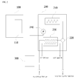
- FIG. 2 is schematic view of a micro-cogeneration system in accordance with an exemplary embodiment of the present invention.
- the cogeneration system in accordance with the present invention includes a co-generator 100 configured to recover waste heat using a heat transfer medium generated when electricity is generated, a boiler 200 configured to selectively circulate the heat transfer medium supplied from the co-generator 100 to any one of a place to be heated and a hot-water supply heat exchanger 230, and a heat transfer medium reservoir tank 300 configured to store the circulated heat transfer medium.
- the heat transfer medium refers to water, which is heating water.
- the co-generator 100 is an apparatus driven by, for example, a turbine (not shown) to generate electricity and simultaneously recover waste heat generated by the turbine.
- a heat exchanger 110 is installed at the co-generator 100 to recover the waste heat.
- the heat exchanger 110 is configured such that a heat transfer medium flows to recover the waste heat, and the heat transfer medium circulates the boiler 200.
- the boiler 200 includes a burner (not shown) configured to generate combustion heat, a main heat exchanger 210 configured to heat-exchange the combustion heat generated from the burner with the heat transfer medium supplied from the heat exchanger 110, a three-way valve 220 configured to selectively circulate the heat transfer medium supplied from the main heat exchanger 210 to any one of a place to be heated and the hot-water supply heat exchanger 230, a hot-water supply heat exchanger 230 configured to heat-exchange the heat transfer medium passing through the three-way valve 220 with tap water in a hot water mode, and a circulation pump 240 having an outlet side connected to the heat exchanger 110 of the co-generator 100 to circulate the heat transfer medium.
- a burner not shown
- main heat exchanger 210 configured to heat-exchange the combustion heat generated from the burner with the heat transfer medium supplied from the heat exchanger 110
- a three-way valve 220 configured to selectively circulate the heat transfer medium supplied from the main heat exchanger 210 to any one of a place to be heated and
- the tap water is introduced into the hot-water supply heat exchanger 230, and the tap water is heat-exchanged with the heat transfer medium passing through the three-way valve 220 to become hot water and then is supplied to a place at which the hot water is required.
- the heat transfer medium reservoir tank 300 is constituted by a sealed vessel to store the heat transfer medium and accumulate heat.
- the heat transfer medium having a temperature lowered after circulation of the place to be heated in the heating mode, i.e., returned water, is introduced into the heat transfer medium reservoir tank 300, and the heat transfer medium having a temperature lowered while passing through the hot-water supply heat exchanger 230 in the hot water mode is introduced into the heat transfer medium reservoir tank 300.
- the heat transfer medium introduced as described above is supplied into the heat exchanger 110 by driving the circulation pump 240, and for this, a pipe line through which the heat transfer medium flows is connected between the heat transfer medium reservoir tank 300 and the circulation pump 240.
- the system can be very simply configured.
- the heat transfer medium that absorbed the waste heat while passing though the heat exchanger 110 of the co-generator 100 may be supplied to the place to be heated and the hot-water supply heat exchanger 230 to use the waste heat for both of heating and hot water.
- the heat transfer medium channels (a heating channel and a hot water channel) of the co-generator and the boiler can be connected to each other while only the co-generator can be operated to accumulate heat energy when there is no hot water and heating load so that the accumulated heat energy can be used for both of heating and hot water, energy efficiency can be improved.
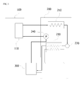
- FIG. 3 is a view showing a path through which the heat transfer medium circulates when there is no heating and hot water load in a cogeneration system of the present invention.
- circulation pump 240 in the boiler 200 is operated to circulate the heat transfer medium.
- the circulation pump 240 When the circulation pump 240 is operated, the heat transfer medium stored in the heat transfer medium reservoir tank 300 is introduced into the heat exchanger 110 of the co-generator 100 via the circulation pump 240.
- the co-generator 100 is operated to generate electricity and simultaneously waste heat, and heat energy is transmitted to the heat transfer medium passing through the heat exchanger 110 by the waste heat.
- the heat transfer medium passing through the heat exchanger 110 is supplied into the three-way valve 220 via the main heat exchanger 210.
- the heat transfer medium is supplied to the hot-water supply heat exchanger 230. In this case, since there is no hot water load, there is no heat exchange with tap water.
- the heat transfer medium passing through the hot-water supply heat exchanger 230 is introduced into the heat transfer medium reservoir tank 300.
- the heat transfer medium is circulated by repeating the above processes, and the closed circuit connected as described above forms a heat transfer medium channel.
- Detection of the temperature of the heat transfer medium is performed by a temperature detection means (not shown) installed at the heat transfer medium reservoir tank 300.
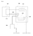
- FIG. 4 is a view showing a path through which the heat transfer medium circulates in the cogeneration system of the present invention in a heating mode.
- the boiler 200 When the heating mode is performed, the boiler 200 is operated to perform combustion in the burner (not shown), and the three-way valve 220 is set to block a flow of the heat transfer medium toward the hot-water supply heat exchanger 230 and allow a flow of the heat transfer medium toward the place to be heated.
- the boiler 200 may be configured to be operated only when a temperature of the heat transfer medium in the heat transfer medium reservoir tank 300 is measured and it is determined as a result of the measurement that the heat transfer medium in the heat transfer medium reservoir tank 300 is insufficient for a heating requirement.
- the circulation pump 240 When the circulation pump 240 is driven, the heat transfer medium stored in the heat transfer medium reservoir tank 300 is introduced into the heat exchanger 110 of the co-generator 100 via the circulation pump 240.
- the co-generator 100 may be shut down or may be operated to generate electricity to transmit heat energy to the heat transfer medium passing through the heat exchanger 110 using the waste heat generated therethrough.
- the heat transfer medium passing through the heat exchanger 110 is heated by the combustion heat of the burner (not shown) via the main heat exchanger 210, and then supplied into the three-way valve 220.
- the heat transfer medium which is heating supply water, passes through the place to be heated and is decreased in temperature, and then returns to be introduced into the heat transfer medium reservoir tank 300.
- FIG. 5 is a view showing a path through which the heat transfer medium circulates in the cogeneration system of the present invention in the hot water mode.
- the boiler 200 When the hot water mode is performed, the boiler 200 is operated to perform combustion in the burner (not shown), and the three-way valve 220 is set to block a flow of the heat transfer medium toward the place to be heated and allow a flow of the heat transfer medium toward the hot-water supply heat exchanger 230.
- the boiler 200 may be configured to be operated only when a temperature of the heat transfer medium in the heat transfer medium reservoir tank 300 is measured and it is determined as a result of the measurement that the heat transfer medium in the heat transfer medium reservoir tank 300 is insufficient for a hot water requirement.
- the flow of the heat transfer medium in the hot water mode is the same as the path of the heat transfer medium described with reference to FIG. 3 .
- the co-generator 100 may be shut down or may be operated to generate electricity to transfer heat energy to the heat transfer medium passing through the heat exchanger 110 by the waste heat generated therethrough.
- the main heat exchanger 210 heats the heat transfer medium using combustion heat of the burner (not shown), and then, supplies the heat transfer medium to the three-way valve 220.
- the hot-water supply heat exchanger 230 decreases the temperature of the heat transfer medium through heat exchange with tap water, and then introduces the heat transfer medium into the heat transfer medium reservoir tank 300.
- the processes are repeated to circulate the heat transfer medium, and the closed circuit connected as described above configures a hot water channel.
- a calorie control system of the boiler 200 can be used to precisely control the calories required to supply heating and hot water.
- the heat energy accumulated in the heat transfer medium reservoir tank 300 is used for heating or hot water, and only the co-generator 100 is operated when there is no heating and hot water load, reducing a cost consumed by the operation of the cogeneration system.
Landscapes
- Engineering & Computer Science (AREA)
- Physics & Mathematics (AREA)
- Thermal Sciences (AREA)
- Chemical & Material Sciences (AREA)
- Combustion & Propulsion (AREA)
- Mechanical Engineering (AREA)
- General Engineering & Computer Science (AREA)
- Water Supply & Treatment (AREA)
- Heat-Pump Type And Storage Water Heaters (AREA)
- Steam Or Hot-Water Central Heating Systems (AREA)
Abstract
Description
- The present invention relates to an operation method for a micro-cogeneration system, and more particularly, to an operation method for a micro-cogeneration system capable of using waste heat generated from a co-generator in both of heating and hot-water supply.
- A micro-cogeneration system, also referred to as a "combined heat and power (CHP) system, is a general energy system in which chemical energy of fuel is converted into electric energy by various motors such as an internal combustion engine, a gas turbine, a fuel cell, a Stirling engine, and so on, and waste heat accompanied at this time is effectively utilized.
- Since such a generation method is an example of high efficiency energy technology capable of improving energy use efficiency two times or more in comparison with a conventional generation method and simultaneously an environment-friendly technique capable of remarkably reducing a discharge amount of CO, which has the highest level of contribution to global warming, all countries of the world are actively introducing such generation methods.
- One example of such a micro-cogeneration system is disclosed in Korean Patent Registration No.
713620 -
FIG. 1 is a schematic view showing a conventional cogeneration and individual heating integrated system, which is disclosed in Korean Patent Registration No.713620 - The conventional cogeneration and individual heating integrated system includes a
co-generator 10 configured to receive a gas and generate electricity, a wasteheat recovery pipe 40 through which cooling water flows and configured to recover waste heat from theco-generator 10, a closed hot-water supply tank 30 configured to receive hot water through awater supply port 31 connected to one side of a lower portion, a hot-watersupply heating pipe 90 connected to a lower side of the hot-water supply tank 30 to circulate water filled in the hot-water supply tank 30 and receive heat from the wasteheat recovery pipe 40 through aheat exchanger 20 to accumulate the heat in the hot-water supply tank 30, a hot-water supply pipe 32 connected to an upper end of the hot-water supply tank 30 to discharge the supplied hot water using a pressure when the hot water is supplied into the hot-water supply tank 30 through thewater supply port 31, anindividual boiler 70 configured to heat the hot water supplied through the hot-water supply pipe 32 and discharge the hot water to atap water valve 60 through a hot-water pipe 50, abranch pipe 80 connected between the hot-water supply pipe 32 and the hot-water pipe 50, aswitch valve 33 disposed between the branch pipe of the hot-water supply pipe 32 and the individual boiler to switch supply of the hot water, aswitch valve 51 disposed on the hot-water pipe 50, and aswitch valve 81 arbitrarily disposed on thebranch pipe 80. - The conventional cogeneration system as described above has a problem in that the waste heat recovered from the
co-generator 10 can be used only during a hot water operation in which hot water is supplied, i.e., upon hot-water supply, and cannot be used during a heating operation. - In addition, since cooling water circulating in the waste
heat recovery pipe 40 is required to recover the waste heat from theco-generator 10, and theheat exchanger 20 configured to absorb heat from the cooling water and the hot-watersupply heating pipe 90 and a circulation pump configured to circulate water in the hot-water supply tank 30 should be further installed, the entire structure is complicated and costs of installing and operating the system are increased. - Further, since the
co-generator 10 and theindividual boiler 70 are systematically separated from each other, when the waste heat is used for the hot water or heating, calories cannot be precisely controlled. - In order to solve the foregoing and/or other problems, it is an aspect of the present invention to provide an operation method for a micro-cogeneration system, in which a co-generator is connected to a heat transfer medium channel of a boiler to use heat recovered from the co-generator for both of heating and hot water, so that a cost consumed to operate the cogeneration system can be reduced and calories supplied during a heating and hot water mode can be easily controlled.
- The foregoing and/or other aspects of the present invention may be achieved by providing an operation method for a micro-cogeneration system including: operating a
co-generator 100 including aheat exchanger 110 to recover waste heat generated when electricity is generated; storing a heat transfer medium supplied from theco-generator 100 in a heat transfermedium reservoir tank 300 via aboiler 200 connected to theheat exchanger 110 and controlling the heat transfer medium stored in the heat transfermedium reservoir tank 300 to be circulated to theheat exchanger 110 of theco-generator 100; operating only theco-generator 100 when there is no heating and hot water load; and stopping the operation of theco-generator 100 when it is determined that a heat transfer medium temperature in the heat transfermedium reservoir tank 300 arrives at a preset temperature. - According to the present invention, as a co-generator is integrally connected to a heat transfer medium channel of a boiler, a system configuration can be simplified and waste heat recovered from the co-generator can be used in both of heating and hot water, reducing a cost consumed to operate the system.
- In addition, as a heat transfer medium is circulated in a state in which the co-generator is integrally connected to the heat transfer medium channel of the boiler, calories supplied for heating or hot water can be precisely controlled.
- Further, when there is no hot water and heating load, heat energy can be accumulated by operating only the co-generator, and since the accumulated heat energy can be used in both of heating and hot water, energy efficiency can be increased.
- The above and other aspects and advantages of the present invention will become apparent and more readily appreciated from the following description of exemplary embodiments, taken in conjunction with the accompanying drawings of which:
-
FIG. 1 is a schematic view showing a conventional cogeneration and individual heating integrated system; -
FIG. 2 is schematic view of a micro-cogeneration system in accordance with an exemplary embodiment of the present invention; -
FIG. 3 is a view showing a path through which a heat transfer medium is circulated when there is no heating and hot water load in the cogeneration system of the present invention; -
FIG. 4 is a view showing a path through which the heat transfer medium is circulated in the cogeneration system of the present invention in a heating mode; and -
FIG. 5 is a view showing a path through which the heat transfer medium is circulated in the cogeneration system of the present invention in a hot water mode. -
- 100:
- Co-generator
- 110:
- Heat exchange part
- 200:
- Boiler
- 210:
- Main heat exchanger
- 220:
- Three-way valve
- 230:
- Hot-water supply heat exchanger
- 240:
- Circulation pump
- 300:
- Heat transfer medium reservoir tank
- Reference will now be made in detail to the embodiments of the present invention, examples of which are illustrated in the accompanying drawings.
-
FIG. 2 is schematic view of a micro-cogeneration system in accordance with an exemplary embodiment of the present invention. - The cogeneration system in accordance with the present invention includes a
co-generator 100 configured to recover waste heat using a heat transfer medium generated when electricity is generated, aboiler 200 configured to selectively circulate the heat transfer medium supplied from theco-generator 100 to any one of a place to be heated and a hot-watersupply heat exchanger 230, and a heat transfermedium reservoir tank 300 configured to store the circulated heat transfer medium. - Here, the heat transfer medium refers to water, which is heating water.
- The
co-generator 100 is an apparatus driven by, for example, a turbine (not shown) to generate electricity and simultaneously recover waste heat generated by the turbine. Aheat exchanger 110 is installed at theco-generator 100 to recover the waste heat. Theheat exchanger 110 is configured such that a heat transfer medium flows to recover the waste heat, and the heat transfer medium circulates theboiler 200. - The
boiler 200 includes a burner (not shown) configured to generate combustion heat, amain heat exchanger 210 configured to heat-exchange the combustion heat generated from the burner with the heat transfer medium supplied from theheat exchanger 110, a three-way valve 220 configured to selectively circulate the heat transfer medium supplied from themain heat exchanger 210 to any one of a place to be heated and the hot-watersupply heat exchanger 230, a hot-watersupply heat exchanger 230 configured to heat-exchange the heat transfer medium passing through the three-way valve 220 with tap water in a hot water mode, and acirculation pump 240 having an outlet side connected to theheat exchanger 110 of theco-generator 100 to circulate the heat transfer medium. - The tap water is introduced into the hot-water
supply heat exchanger 230, and the tap water is heat-exchanged with the heat transfer medium passing through the three-way valve 220 to become hot water and then is supplied to a place at which the hot water is required. - The heat transfer
medium reservoir tank 300 is constituted by a sealed vessel to store the heat transfer medium and accumulate heat. The heat transfer medium having a temperature lowered after circulation of the place to be heated in the heating mode, i.e., returned water, is introduced into the heat transfermedium reservoir tank 300, and the heat transfer medium having a temperature lowered while passing through the hot-watersupply heat exchanger 230 in the hot water mode is introduced into the heat transfermedium reservoir tank 300. - The heat transfer medium introduced as described above is supplied into the
heat exchanger 110 by driving thecirculation pump 240, and for this, a pipe line through which the heat transfer medium flows is connected between the heat transfermedium reservoir tank 300 and thecirculation pump 240. - According to the above structure, since the
heat exchanger 110 of theco-generator 100 and a heating water circulation circuit of theboiler 200 configure one connected channel, the system can be very simply configured. - In addition, the heat transfer medium that absorbed the waste heat while passing though the
heat exchanger 110 of theco-generator 100 may be supplied to the place to be heated and the hot-watersupply heat exchanger 230 to use the waste heat for both of heating and hot water. - Further, since the heat transfer medium channels (a heating channel and a hot water channel) of the co-generator and the boiler can be connected to each other while only the co-generator can be operated to accumulate heat energy when there is no hot water and heating load so that the accumulated heat energy can be used for both of heating and hot water, energy efficiency can be improved.
- Hereinafter, an operation method of the present invention will be described with reference to
FIGS. 3 to 5 . -
FIG. 3 is a view showing a path through which the heat transfer medium circulates when there is no heating and hot water load in a cogeneration system of the present invention. - When there is no heating and hot water load, an operation of the
boiler 200 is stopped, and only theco-generator 100 is operated. - Of course, the
circulation pump 240 in theboiler 200 is operated to circulate the heat transfer medium. - When the
circulation pump 240 is operated, the heat transfer medium stored in the heat transfermedium reservoir tank 300 is introduced into theheat exchanger 110 of theco-generator 100 via thecirculation pump 240. - In this case, the
co-generator 100 is operated to generate electricity and simultaneously waste heat, and heat energy is transmitted to the heat transfer medium passing through theheat exchanger 110 by the waste heat. - The heat transfer medium passing through the
heat exchanger 110 is supplied into the three-way valve 220 via themain heat exchanger 210. - Since the three-
way valve 220 is opened toward the hot-watersupply heat exchanger 230, the heat transfer medium is supplied to the hot-watersupply heat exchanger 230. In this case, since there is no hot water load, there is no heat exchange with tap water. - The heat transfer medium passing through the hot-water
supply heat exchanger 230 is introduced into the heat transfermedium reservoir tank 300. - Next, the heat transfer medium is circulated by repeating the above processes, and the closed circuit connected as described above forms a heat transfer medium channel.
- As described above, when the heat transfer medium is circulated, heat energy is accumulated in the heat transfer
medium reservoir tank 300, and when it is determined that a temperature of the heat transfer medium in the heat transfermedium reservoir tank 300 arrives at a preset temperature, the operation of the co-generator 100 is stopped. - Detection of the temperature of the heat transfer medium is performed by a temperature detection means (not shown) installed at the heat transfer
medium reservoir tank 300. -
FIG. 4 is a view showing a path through which the heat transfer medium circulates in the cogeneration system of the present invention in a heating mode. - When the heating mode is performed, the
boiler 200 is operated to perform combustion in the burner (not shown), and the three-way valve 220 is set to block a flow of the heat transfer medium toward the hot-watersupply heat exchanger 230 and allow a flow of the heat transfer medium toward the place to be heated. - Here, the
boiler 200 may be configured to be operated only when a temperature of the heat transfer medium in the heat transfermedium reservoir tank 300 is measured and it is determined as a result of the measurement that the heat transfer medium in the heat transfermedium reservoir tank 300 is insufficient for a heating requirement. - When the
circulation pump 240 is driven, the heat transfer medium stored in the heat transfermedium reservoir tank 300 is introduced into theheat exchanger 110 of the co-generator 100 via thecirculation pump 240. - In this case, the co-generator 100 may be shut down or may be operated to generate electricity to transmit heat energy to the heat transfer medium passing through the
heat exchanger 110 using the waste heat generated therethrough. - The heat transfer medium passing through the
heat exchanger 110 is heated by the combustion heat of the burner (not shown) via themain heat exchanger 210, and then supplied into the three-way valve 220. - Since the three-
way valve 220 is opened toward the place to be heated, the heat transfer medium, which is heating supply water, passes through the place to be heated and is decreased in temperature, and then returns to be introduced into the heat transfermedium reservoir tank 300. - Next, in the heating mode, the above processes are repeated to circulate the heat transfer medium, and the closed circuit connected as described above configures a heating channel.
- While the case in which the combustion is performed in the burner has been described, when the heating can be performed by only the heat energy accumulated in the heat transfer
medium reservoir tank 300, only the co-generator 100 may be controlled to be operated with no combustion in the burner. -
FIG. 5 is a view showing a path through which the heat transfer medium circulates in the cogeneration system of the present invention in the hot water mode. - When the hot water mode is performed, the
boiler 200 is operated to perform combustion in the burner (not shown), and the three-way valve 220 is set to block a flow of the heat transfer medium toward the place to be heated and allow a flow of the heat transfer medium toward the hot-watersupply heat exchanger 230. - Here, the
boiler 200 may be configured to be operated only when a temperature of the heat transfer medium in the heat transfermedium reservoir tank 300 is measured and it is determined as a result of the measurement that the heat transfer medium in the heat transfermedium reservoir tank 300 is insufficient for a hot water requirement. - The flow of the heat transfer medium in the hot water mode is the same as the path of the heat transfer medium described with reference to
FIG. 3 . - In the hot water mode, the co-generator 100 may be shut down or may be operated to generate electricity to transfer heat energy to the heat transfer medium passing through the
heat exchanger 110 by the waste heat generated therethrough. - The
main heat exchanger 210 heats the heat transfer medium using combustion heat of the burner (not shown), and then, supplies the heat transfer medium to the three-way valve 220. - The hot-water
supply heat exchanger 230 decreases the temperature of the heat transfer medium through heat exchange with tap water, and then introduces the heat transfer medium into the heat transfermedium reservoir tank 300. - Next, in the hot water mode, the processes are repeated to circulate the heat transfer medium, and the closed circuit connected as described above configures a hot water channel.
- While the case in which the combustion is performed in the burner has been described, when the hot water can be supplied by only the heat energy accumulated in the heat transfer
medium reservoir tank 300, only the co-generator 100 may be controlled to be operated with no combustion in the burner. - As described above, in the co-generator 100 integrally connected to the heat transfer medium channel of the
boiler 200, a calorie control system of theboiler 200 can be used to precisely control the calories required to supply heating and hot water. - In addition, the heat energy accumulated in the heat transfer
medium reservoir tank 300 is used for heating or hot water, and only the co-generator 100 is operated when there is no heating and hot water load, reducing a cost consumed by the operation of the cogeneration system.
Claims (4)
- An operation method for a micro-cogeneration system, comprising:operating a co-generator (100) including a heat exchanger (110) to recover waste heat generated when electricity is generated;storing a heat transfer medium supplied from the co-generator (100) in a heat transfer medium reservoir tank (300) via a boiler (200) connected to the heat exchanger (110) and controlling the heat transfer medium stored in the heat transfer medium reservoir tank (300) to be circulated to the heat exchanger (110) of the co-generator (100);operating only the co-generator (100) when there is no heating and hot water load; andstopping the operation of the co-generator (100) when it is determined that a heat transfer medium temperature in the heat transfer medium reservoir tank (300) arrives at a preset temperature.
- The operation method for a micro-cogeneration system according to claim 1, wherein, when there is no heating and hot water load, a circulation channel of the heat transfer medium forms a heat transfer medium channel by sequentially connecting the heat transfer medium reservoir tank (300), a circulation pump (240) installed in the boiler (200) to circulate the heat transfer medium in the heat transfer medium reservoir tank (300), the heat exchanger (110) of the co-generator (100) connected to the circulation pump (240), a main heat exchanger (210) connected to the heat exchanger (110) and installed in the boiler (200), a three-way valve (220) configured to selectively supply the heat transfer medium supplied from the main heat exchanger (210) to any one of a place to be heated and a hot-water supply heat exchanger (230), and the hot-water supply heat exchanger (230) connected to the three-way valve (220).
- The operation method for a micro-cogeneration system according to claim 1, wherein, as the heat transfer medium supplied from the main heat exchanger (210) of the boiler (200) is selectively supplied to any one of the place to be heated and the hot-water supply heat exchanger (230), the heat transfer medium stored in the heat transfer medium reservoir tank (300) is used for heating and hot water.
- The operation method for a micro-cogeneration system according to any one of claims 1 to 3, wherein the boiler is operated only when the heat transfer medium stored in the heat transfer medium reservoir tank (300) is insufficient for a heating or hot water requirement.
Applications Claiming Priority (2)
| Application Number | Priority Date | Filing Date | Title |
|---|---|---|---|
| KR1020090093860A KR101199687B1 (en) | 2009-10-01 | 2009-10-01 | Operating method of compact cogeneration system |
| PCT/KR2010/006090 WO2011040714A2 (en) | 2009-10-01 | 2010-09-08 | Operation method for micro-cogeneration system |
Publications (3)
| Publication Number | Publication Date |
|---|---|
| EP2484983A2 true EP2484983A2 (en) | 2012-08-08 |
| EP2484983A4 EP2484983A4 (en) | 2016-06-08 |
| EP2484983B1 EP2484983B1 (en) | 2017-09-27 |
Family
ID=43826756
Family Applications (1)
| Application Number | Title | Priority Date | Filing Date |
|---|---|---|---|
| EP10820787.9A Not-in-force EP2484983B1 (en) | 2009-10-01 | 2010-09-08 | Operation method for micro-cogeneration system |
Country Status (4)
| Country | Link |
|---|---|
| EP (1) | EP2484983B1 (en) |
| JP (1) | JP2013506810A (en) |
| KR (1) | KR101199687B1 (en) |
| WO (1) | WO2011040714A2 (en) |
Cited By (1)
| Publication number | Priority date | Publication date | Assignee | Title |
|---|---|---|---|---|
| US12455098B2 (en) | 2022-04-12 | 2025-10-28 | The Cleaver-Brooks Company, Inc. | Thermal efficiency system and method for boiler plant |
Families Citing this family (3)
| Publication number | Priority date | Publication date | Assignee | Title |
|---|---|---|---|---|
| KR101436842B1 (en) * | 2012-12-26 | 2014-09-11 | 주식회사 경동나비엔 | Method for preventing freezing of heating pipe and hot-water pipe of boiler |
| CN106679185A (en) * | 2016-08-30 | 2017-05-17 | 神华集团有限责任公司 | Method an device for boiler water heating before startup of boiler |
| KR102443231B1 (en) * | 2018-03-21 | 2022-09-15 | 아세아열기 주식회사 | Heating and air-conditioning equipment for central heating and household boilers and control method thereof |
Family Cites Families (12)
| Publication number | Priority date | Publication date | Assignee | Title |
|---|---|---|---|---|
| DE19740398C2 (en) * | 1997-09-09 | 1999-12-02 | Vng Verbundnetz Gas Ag | Combined heat and power facility for energy supply |
| KR100409134B1 (en) * | 2001-10-11 | 2003-12-12 | (주)세티 | Cogeneration System for Fuel Cell |
| KR100418459B1 (en) * | 2001-11-26 | 2004-02-14 | (주)세티 | Apparatus for Supplying Waste Energy from Fuel Cell to Boiler |
| JP3834567B2 (en) * | 2003-05-23 | 2006-10-18 | ネポン株式会社 | Carbon dioxide gas supply system combined with exhaust heat recovery in greenhouse for horticulture |
| JP2005291561A (en) * | 2004-03-31 | 2005-10-20 | Osaka Gas Co Ltd | Operating method for cogeneration system and cogeneration system |
| AT413757B (en) * | 2004-09-13 | 2006-05-15 | Vaillant Gmbh | METHOD FOR GUARANTEING A HIGH HOT WATER COMFORT IN HOT WATER HEATERS HEATED WITH FUEL CELL HEATING EQUIPMENT |
| KR100626993B1 (en) * | 2005-01-20 | 2006-09-25 | 케이이설비연구소주식회사 | Energy-saving combined heating system that combines central heating with city gas fuel source heating and cogeneration |
| JP4421543B2 (en) * | 2005-10-18 | 2010-02-24 | リンナイ株式会社 | Cogeneration system |
| KR100713620B1 (en) | 2006-05-26 | 2007-05-02 | 벽산건설 주식회사 | Combined cogeneration and individual heating system |
| KR100740542B1 (en) | 2006-05-30 | 2007-07-18 | 최성환 | Fuel Cell Waste Heat Recovery System |
| JP4727680B2 (en) * | 2008-02-25 | 2011-07-20 | 株式会社ノーリツ | Water heater |
| JP2009204203A (en) * | 2008-02-27 | 2009-09-10 | Noritz Corp | Cogeneration system |
-
2009
- 2009-10-01 KR KR1020090093860A patent/KR101199687B1/en active Active
-
2010
- 2010-09-08 WO PCT/KR2010/006090 patent/WO2011040714A2/en not_active Ceased
- 2010-09-08 EP EP10820787.9A patent/EP2484983B1/en not_active Not-in-force
- 2010-09-08 JP JP2012532000A patent/JP2013506810A/en active Pending
Non-Patent Citations (1)
| Title |
|---|
| See references of WO2011040714A2 * |
Cited By (1)
| Publication number | Priority date | Publication date | Assignee | Title |
|---|---|---|---|---|
| US12455098B2 (en) | 2022-04-12 | 2025-10-28 | The Cleaver-Brooks Company, Inc. | Thermal efficiency system and method for boiler plant |
Also Published As
| Publication number | Publication date |
|---|---|
| EP2484983A4 (en) | 2016-06-08 |
| KR20110036284A (en) | 2011-04-07 |
| JP2013506810A (en) | 2013-02-28 |
| WO2011040714A2 (en) | 2011-04-07 |
| WO2011040714A3 (en) | 2011-07-21 |
| EP2484983B1 (en) | 2017-09-27 |
| KR101199687B1 (en) | 2012-11-08 |
Similar Documents
| Publication | Publication Date | Title |
|---|---|---|
| EP1669700A1 (en) | Cooling/heating apparatus using waste heat from fuel cell | |
| KR101173746B1 (en) | Compact cogeneration system and controlling method of the compact cogeneration system | |
| EP2784401A1 (en) | Hot water supply apparatus | |
| KR100740542B1 (en) | Fuel Cell Waste Heat Recovery System | |
| EP2484983B1 (en) | Operation method for micro-cogeneration system | |
| KR101078964B1 (en) | Fuel cell system | |
| JP5598083B2 (en) | Waste heat recovery system and cogeneration system | |
| EP3322016A1 (en) | Fuel cell system | |
| JP2004060980A (en) | Cogeneration system | |
| KR101518381B1 (en) | Co-generation and Control method of the same | |
| JP3563681B2 (en) | Fuel cell cogeneration system and method of operating fuel cell cogeneration system | |
| JP3933543B2 (en) | Heat medium supply device | |
| JP2016008787A (en) | Heat interchange unit | |
| JP6088771B2 (en) | Heat source equipment | |
| JP2020153613A (en) | Energy supply system | |
| JP2007263010A (en) | Cogeneration system | |
| JP4850118B2 (en) | Hot water supply piping heat insulation operation method in hot water storage type hot water supply system | |
| JP5317810B2 (en) | Water heater | |
| JP2004020081A (en) | Power generation heat utilization system | |
| JP2013069598A (en) | Cogeneration system | |
| JP2012197987A (en) | Heat pump water heater | |
| KR20110036289A (en) | Compact cogeneration system | |
| KR20110036285A (en) | Small cogeneration system | |
| JP2004053151A (en) | Hot water supply device | |
| JP2016207581A (en) | Fuel cell cogeneration system |
Legal Events
| Date | Code | Title | Description |
|---|---|---|---|
| PUAI | Public reference made under article 153(3) epc to a published international application that has entered the european phase |
Free format text: ORIGINAL CODE: 0009012 |
|
| 17P | Request for examination filed |
Effective date: 20120428 |
|
| AK | Designated contracting states |
Kind code of ref document: A2 Designated state(s): AL AT BE BG CH CY CZ DE DK EE ES FI FR GB GR HR HU IE IS IT LI LT LU LV MC MK MT NL NO PL PT RO SE SI SK SM TR |
|
| DAX | Request for extension of the european patent (deleted) | ||
| A4 | Supplementary search report drawn up and despatched |
Effective date: 20160511 |
|
| RIC1 | Information provided on ipc code assigned before grant |
Ipc: F24D 19/10 20060101ALI20160504BHEP Ipc: F24D 10/00 20060101AFI20160504BHEP Ipc: F24D 12/02 20060101ALI20160504BHEP |
|
| RIC1 | Information provided on ipc code assigned before grant |
Ipc: F24D 12/02 20060101ALI20170313BHEP Ipc: F24D 19/10 20060101ALI20170313BHEP Ipc: F24D 10/00 20060101AFI20170313BHEP |
|
| GRAP | Despatch of communication of intention to grant a patent |
Free format text: ORIGINAL CODE: EPIDOSNIGR1 |
|
| INTG | Intention to grant announced |
Effective date: 20170424 |
|
| GRAS | Grant fee paid |
Free format text: ORIGINAL CODE: EPIDOSNIGR3 |
|
| GRAA | (expected) grant |
Free format text: ORIGINAL CODE: 0009210 |
|
| AK | Designated contracting states |
Kind code of ref document: B1 Designated state(s): AL AT BE BG CH CY CZ DE DK EE ES FI FR GB GR HR HU IE IS IT LI LT LU LV MC MK MT NL NO PL PT RO SE SI SK SM TR |
|
| REG | Reference to a national code |
Ref country code: GB Ref legal event code: FG4D |
|
| REG | Reference to a national code |
Ref country code: CH Ref legal event code: EP |
|
| REG | Reference to a national code |
Ref country code: AT Ref legal event code: REF Ref document number: 932317 Country of ref document: AT Kind code of ref document: T Effective date: 20171015 |
|
| REG | Reference to a national code |
Ref country code: IE Ref legal event code: FG4D |
|
| REG | Reference to a national code |
Ref country code: DE Ref legal event code: R096 Ref document number: 602010045616 Country of ref document: DE |
|
| REG | Reference to a national code |
Ref country code: NL Ref legal event code: FP |
|
| PG25 | Lapsed in a contracting state [announced via postgrant information from national office to epo] |
Ref country code: HR Free format text: LAPSE BECAUSE OF FAILURE TO SUBMIT A TRANSLATION OF THE DESCRIPTION OR TO PAY THE FEE WITHIN THE PRESCRIBED TIME-LIMIT Effective date: 20170927 Ref country code: FI Free format text: LAPSE BECAUSE OF FAILURE TO SUBMIT A TRANSLATION OF THE DESCRIPTION OR TO PAY THE FEE WITHIN THE PRESCRIBED TIME-LIMIT Effective date: 20170927 Ref country code: SE Free format text: LAPSE BECAUSE OF FAILURE TO SUBMIT A TRANSLATION OF THE DESCRIPTION OR TO PAY THE FEE WITHIN THE PRESCRIBED TIME-LIMIT Effective date: 20170927 Ref country code: NO Free format text: LAPSE BECAUSE OF FAILURE TO SUBMIT A TRANSLATION OF THE DESCRIPTION OR TO PAY THE FEE WITHIN THE PRESCRIBED TIME-LIMIT Effective date: 20171227 Ref country code: LT Free format text: LAPSE BECAUSE OF FAILURE TO SUBMIT A TRANSLATION OF THE DESCRIPTION OR TO PAY THE FEE WITHIN THE PRESCRIBED TIME-LIMIT Effective date: 20170927 |
|
| REG | Reference to a national code |
Ref country code: LT Ref legal event code: MG4D |
|
| REG | Reference to a national code |
Ref country code: AT Ref legal event code: MK05 Ref document number: 932317 Country of ref document: AT Kind code of ref document: T Effective date: 20170927 |
|
| PG25 | Lapsed in a contracting state [announced via postgrant information from national office to epo] |
Ref country code: LV Free format text: LAPSE BECAUSE OF FAILURE TO SUBMIT A TRANSLATION OF THE DESCRIPTION OR TO PAY THE FEE WITHIN THE PRESCRIBED TIME-LIMIT Effective date: 20170927 Ref country code: GR Free format text: LAPSE BECAUSE OF FAILURE TO SUBMIT A TRANSLATION OF THE DESCRIPTION OR TO PAY THE FEE WITHIN THE PRESCRIBED TIME-LIMIT Effective date: 20171228 Ref country code: BG Free format text: LAPSE BECAUSE OF FAILURE TO SUBMIT A TRANSLATION OF THE DESCRIPTION OR TO PAY THE FEE WITHIN THE PRESCRIBED TIME-LIMIT Effective date: 20171227 |
|
| PG25 | Lapsed in a contracting state [announced via postgrant information from national office to epo] |
Ref country code: ES Free format text: LAPSE BECAUSE OF FAILURE TO SUBMIT A TRANSLATION OF THE DESCRIPTION OR TO PAY THE FEE WITHIN THE PRESCRIBED TIME-LIMIT Effective date: 20170927 Ref country code: RO Free format text: LAPSE BECAUSE OF FAILURE TO SUBMIT A TRANSLATION OF THE DESCRIPTION OR TO PAY THE FEE WITHIN THE PRESCRIBED TIME-LIMIT Effective date: 20170927 Ref country code: CZ Free format text: LAPSE BECAUSE OF FAILURE TO SUBMIT A TRANSLATION OF THE DESCRIPTION OR TO PAY THE FEE WITHIN THE PRESCRIBED TIME-LIMIT Effective date: 20170927 |
|
| PG25 | Lapsed in a contracting state [announced via postgrant information from national office to epo] |
Ref country code: EE Free format text: LAPSE BECAUSE OF FAILURE TO SUBMIT A TRANSLATION OF THE DESCRIPTION OR TO PAY THE FEE WITHIN THE PRESCRIBED TIME-LIMIT Effective date: 20170927 Ref country code: SM Free format text: LAPSE BECAUSE OF FAILURE TO SUBMIT A TRANSLATION OF THE DESCRIPTION OR TO PAY THE FEE WITHIN THE PRESCRIBED TIME-LIMIT Effective date: 20170927 Ref country code: AT Free format text: LAPSE BECAUSE OF FAILURE TO SUBMIT A TRANSLATION OF THE DESCRIPTION OR TO PAY THE FEE WITHIN THE PRESCRIBED TIME-LIMIT Effective date: 20170927 Ref country code: IS Free format text: LAPSE BECAUSE OF FAILURE TO SUBMIT A TRANSLATION OF THE DESCRIPTION OR TO PAY THE FEE WITHIN THE PRESCRIBED TIME-LIMIT Effective date: 20180127 Ref country code: IT Free format text: LAPSE BECAUSE OF FAILURE TO SUBMIT A TRANSLATION OF THE DESCRIPTION OR TO PAY THE FEE WITHIN THE PRESCRIBED TIME-LIMIT Effective date: 20170927 Ref country code: SK Free format text: LAPSE BECAUSE OF FAILURE TO SUBMIT A TRANSLATION OF THE DESCRIPTION OR TO PAY THE FEE WITHIN THE PRESCRIBED TIME-LIMIT Effective date: 20170927 |
|
| REG | Reference to a national code |
Ref country code: DE Ref legal event code: R097 Ref document number: 602010045616 Country of ref document: DE |
|
| PG25 | Lapsed in a contracting state [announced via postgrant information from national office to epo] |
Ref country code: DK Free format text: LAPSE BECAUSE OF FAILURE TO SUBMIT A TRANSLATION OF THE DESCRIPTION OR TO PAY THE FEE WITHIN THE PRESCRIBED TIME-LIMIT Effective date: 20170927 |
|
| PLBE | No opposition filed within time limit |
Free format text: ORIGINAL CODE: 0009261 |
|
| STAA | Information on the status of an ep patent application or granted ep patent |
Free format text: STATUS: NO OPPOSITION FILED WITHIN TIME LIMIT |
|
| PG25 | Lapsed in a contracting state [announced via postgrant information from national office to epo] |
Ref country code: PL Free format text: LAPSE BECAUSE OF FAILURE TO SUBMIT A TRANSLATION OF THE DESCRIPTION OR TO PAY THE FEE WITHIN THE PRESCRIBED TIME-LIMIT Effective date: 20170927 |
|
| 26N | No opposition filed |
Effective date: 20180628 |
|
| PGFP | Annual fee paid to national office [announced via postgrant information from national office to epo] |
Ref country code: DE Payment date: 20180828 Year of fee payment: 9 |
|
| PG25 | Lapsed in a contracting state [announced via postgrant information from national office to epo] |
Ref country code: SI Free format text: LAPSE BECAUSE OF FAILURE TO SUBMIT A TRANSLATION OF THE DESCRIPTION OR TO PAY THE FEE WITHIN THE PRESCRIBED TIME-LIMIT Effective date: 20170927 |
|
| PGFP | Annual fee paid to national office [announced via postgrant information from national office to epo] |
Ref country code: NL Payment date: 20180912 Year of fee payment: 9 Ref country code: GB Payment date: 20180905 Year of fee payment: 9 |
|
| PG25 | Lapsed in a contracting state [announced via postgrant information from national office to epo] |
Ref country code: MC Free format text: LAPSE BECAUSE OF FAILURE TO SUBMIT A TRANSLATION OF THE DESCRIPTION OR TO PAY THE FEE WITHIN THE PRESCRIBED TIME-LIMIT Effective date: 20170927 |
|
| REG | Reference to a national code |
Ref country code: CH Ref legal event code: PL |
|
| REG | Reference to a national code |
Ref country code: BE Ref legal event code: MM Effective date: 20180930 |
|
| REG | Reference to a national code |
Ref country code: IE Ref legal event code: MM4A |
|
| PG25 | Lapsed in a contracting state [announced via postgrant information from national office to epo] |
Ref country code: LU Free format text: LAPSE BECAUSE OF NON-PAYMENT OF DUE FEES Effective date: 20180908 |
|
| PG25 | Lapsed in a contracting state [announced via postgrant information from national office to epo] |
Ref country code: IE Free format text: LAPSE BECAUSE OF NON-PAYMENT OF DUE FEES Effective date: 20180908 |
|
| PG25 | Lapsed in a contracting state [announced via postgrant information from national office to epo] |
Ref country code: BE Free format text: LAPSE BECAUSE OF NON-PAYMENT OF DUE FEES Effective date: 20180930 Ref country code: FR Free format text: LAPSE BECAUSE OF NON-PAYMENT OF DUE FEES Effective date: 20180930 Ref country code: CH Free format text: LAPSE BECAUSE OF NON-PAYMENT OF DUE FEES Effective date: 20180930 Ref country code: LI Free format text: LAPSE BECAUSE OF NON-PAYMENT OF DUE FEES Effective date: 20180930 |
|
| PG25 | Lapsed in a contracting state [announced via postgrant information from national office to epo] |
Ref country code: MT Free format text: LAPSE BECAUSE OF NON-PAYMENT OF DUE FEES Effective date: 20180908 |
|
| PG25 | Lapsed in a contracting state [announced via postgrant information from national office to epo] |
Ref country code: TR Free format text: LAPSE BECAUSE OF FAILURE TO SUBMIT A TRANSLATION OF THE DESCRIPTION OR TO PAY THE FEE WITHIN THE PRESCRIBED TIME-LIMIT Effective date: 20170927 |
|
| REG | Reference to a national code |
Ref country code: DE Ref legal event code: R119 Ref document number: 602010045616 Country of ref document: DE |
|
| REG | Reference to a national code |
Ref country code: NL Ref legal event code: MM Effective date: 20191001 |
|
| PG25 | Lapsed in a contracting state [announced via postgrant information from national office to epo] |
Ref country code: HU Free format text: LAPSE BECAUSE OF FAILURE TO SUBMIT A TRANSLATION OF THE DESCRIPTION OR TO PAY THE FEE WITHIN THE PRESCRIBED TIME-LIMIT; INVALID AB INITIO Effective date: 20100908 Ref country code: PT Free format text: LAPSE BECAUSE OF FAILURE TO SUBMIT A TRANSLATION OF THE DESCRIPTION OR TO PAY THE FEE WITHIN THE PRESCRIBED TIME-LIMIT Effective date: 20170927 |
|
| PG25 | Lapsed in a contracting state [announced via postgrant information from national office to epo] |
Ref country code: CY Free format text: LAPSE BECAUSE OF FAILURE TO SUBMIT A TRANSLATION OF THE DESCRIPTION OR TO PAY THE FEE WITHIN THE PRESCRIBED TIME-LIMIT Effective date: 20170927 Ref country code: MK Free format text: LAPSE BECAUSE OF NON-PAYMENT OF DUE FEES Effective date: 20170927 |
|
| PG25 | Lapsed in a contracting state [announced via postgrant information from national office to epo] |
Ref country code: NL Free format text: LAPSE BECAUSE OF NON-PAYMENT OF DUE FEES Effective date: 20191001 Ref country code: DE Free format text: LAPSE BECAUSE OF NON-PAYMENT OF DUE FEES Effective date: 20200401 Ref country code: AL Free format text: LAPSE BECAUSE OF FAILURE TO SUBMIT A TRANSLATION OF THE DESCRIPTION OR TO PAY THE FEE WITHIN THE PRESCRIBED TIME-LIMIT Effective date: 20170927 |
|
| GBPC | Gb: european patent ceased through non-payment of renewal fee |
Effective date: 20190908 |
|
| PG25 | Lapsed in a contracting state [announced via postgrant information from national office to epo] |
Ref country code: GB Free format text: LAPSE BECAUSE OF NON-PAYMENT OF DUE FEES Effective date: 20190908 |