EP2483643B1 - Abgaserzeugende einrichtung, insbesondere schiff, mit einer abgasvolumenbestimmung - Google Patents
Abgaserzeugende einrichtung, insbesondere schiff, mit einer abgasvolumenbestimmung Download PDFInfo
- Publication number
- EP2483643B1 EP2483643B1 EP10763343.0A EP10763343A EP2483643B1 EP 2483643 B1 EP2483643 B1 EP 2483643B1 EP 10763343 A EP10763343 A EP 10763343A EP 2483643 B1 EP2483643 B1 EP 2483643B1
- Authority
- EP
- European Patent Office
- Prior art keywords
- exhaust gas
- optical wave
- wave guide
- bragg gratings
- exhaust
- Prior art date
- Legal status (The legal status is an assumption and is not a legal conclusion. Google has not performed a legal analysis and makes no representation as to the accuracy of the status listed.)
- Not-in-force
Links
Images


Classifications
-
- G—PHYSICS
- G01—MEASURING; TESTING
- G01F—MEASURING VOLUME, VOLUME FLOW, MASS FLOW OR LIQUID LEVEL; METERING BY VOLUME
- G01F1/00—Measuring the volume flow or mass flow of fluid or fluent solid material wherein the fluid passes through a meter in a continuous flow
- G01F1/68—Measuring the volume flow or mass flow of fluid or fluent solid material wherein the fluid passes through a meter in a continuous flow by using thermal effects
- G01F1/684—Structural arrangements; Mounting of elements, e.g. in relation to fluid flow
- G01F1/688—Structural arrangements; Mounting of elements, e.g. in relation to fluid flow using a particular type of heating, cooling or sensing element
- G01F1/6884—Structural arrangements; Mounting of elements, e.g. in relation to fluid flow using a particular type of heating, cooling or sensing element making use of temperature dependence of optical properties
-
- G—PHYSICS
- G01—MEASURING; TESTING
- G01K—MEASURING TEMPERATURE; MEASURING QUANTITY OF HEAT; THERMALLY-SENSITIVE ELEMENTS NOT OTHERWISE PROVIDED FOR
- G01K11/00—Measuring temperature based upon physical or chemical changes not covered by groups G01K3/00, G01K5/00, G01K7/00 or G01K9/00
- G01K11/32—Measuring temperature based upon physical or chemical changes not covered by groups G01K3/00, G01K5/00, G01K7/00 or G01K9/00 using changes in transmittance, scattering or luminescence in optical fibres
- G01K11/3206—Measuring temperature based upon physical or chemical changes not covered by groups G01K3/00, G01K5/00, G01K7/00 or G01K9/00 using changes in transmittance, scattering or luminescence in optical fibres at discrete locations in the fibre, e.g. using Bragg scattering
-
- G—PHYSICS
- G01—MEASURING; TESTING
- G01P—MEASURING LINEAR OR ANGULAR SPEED, ACCELERATION, DECELERATION, OR SHOCK; INDICATING PRESENCE, ABSENCE, OR DIRECTION, OF MOVEMENT
- G01P5/00—Measuring speed of fluids, e.g. of air stream; Measuring speed of bodies relative to fluids, e.g. of ship, of aircraft
- G01P5/001—Full-field flow measurement, e.g. determining flow velocity and direction in a whole region at the same time, flow visualisation
-
- G—PHYSICS
- G01—MEASURING; TESTING
- G01P—MEASURING LINEAR OR ANGULAR SPEED, ACCELERATION, DECELERATION, OR SHOCK; INDICATING PRESENCE, ABSENCE, OR DIRECTION, OF MOVEMENT
- G01P5/00—Measuring speed of fluids, e.g. of air stream; Measuring speed of bodies relative to fluids, e.g. of ship, of aircraft
- G01P5/10—Measuring speed of fluids, e.g. of air stream; Measuring speed of bodies relative to fluids, e.g. of ship, of aircraft by measuring thermal variables
-
- F—MECHANICAL ENGINEERING; LIGHTING; HEATING; WEAPONS; BLASTING
- F01—MACHINES OR ENGINES IN GENERAL; ENGINE PLANTS IN GENERAL; STEAM ENGINES
- F01N—GAS-FLOW SILENCERS OR EXHAUST APPARATUS FOR MACHINES OR ENGINES IN GENERAL; GAS-FLOW SILENCERS OR EXHAUST APPARATUS FOR INTERNAL-COMBUSTION ENGINES
- F01N2560/00—Exhaust systems with means for detecting or measuring exhaust gas components or characteristics
- F01N2560/07—Exhaust systems with means for detecting or measuring exhaust gas components or characteristics the means being an exhaust gas flow rate or velocity meter or sensor, intake flow meters only when exclusively used to determine exhaust gas parameters
-
- G—PHYSICS
- G01—MEASURING; TESTING
- G01K—MEASURING TEMPERATURE; MEASURING QUANTITY OF HEAT; THERMALLY-SENSITIVE ELEMENTS NOT OTHERWISE PROVIDED FOR
- G01K2205/00—Application of thermometers in motors, e.g. of a vehicle
- G01K2205/04—Application of thermometers in motors, e.g. of a vehicle for measuring exhaust gas temperature
Definitions
- the invention relates to a gas generating device, in particular a ship, with an exhaust passage, exits the exhaust gas of the device in an environment of the device, and with a device for determining a discharged through the exhaust duct to the environment exhaust gas volume according to claim 1.
- the exhaust gas volume indirectly on the basis of operating parameters of the system, such. from a fuel consumption, a fuel composition, a combustion temperature, etc.
- operating parameters of the system such. from a fuel consumption, a fuel composition, a combustion temperature, etc.
- data and correlations between the operating parameters and the exhaust gas volume provided by the manufacturer or operator of an exhaust gas generator are usually used.
- an exhaust gas generator for example an internal combustion engine or a steam turbine plant
- WO 2004/042326 A2 discloses a measuring element for determining a flow velocity of a fluid flowing around the measuring element with a conductor for guiding an electromagnetic wave along its longitudinal extent and at least one, adjacent to the conductor adjacent, electrical heating element, by means of which the conductor can be acted upon with heat is.
- an electromagnetic wave coupled into the conductor is influenced in accordance with the temperature of the conductor which is dependent on the flow velocity of the fluid.
- EP 1510656 A1 discloses a method and apparatus for detecting an operating condition when operating a turbine in which a hot exhaust gas flows through an exhaust case and the temperature of the exhaust gas in the exhaust case is detected in a time-resolved manner. In this case, several temperature measured values of the exhaust gas are detected spatially resolved.
- DE 19821956 A1 discloses a method for the quantitative analysis of gas volumes by means of emission or absorption spectrometry in the ultraviolet, visible and infrared spectral range.
- geometrically defined and reproducibly adjustable observation levels are determined, which are each aligned perpendicular to the longitudinal axis of an exhaust gas jet, and measurement series carried out with spectral measurements, the optical axis of a spectrometer is always in an observation plane.
- An exhaust gas generating device has a device for determining the exhaust gas volume, which comprises a plurality of transverse to the flow direction of an exhaust gas at the end of the exhaust duct at predetermined positions arranged Bragg gratings formed in an optical waveguide structure consisting of at least one optical waveguide, adjacent
- a heating device is arranged, with which the Bragg gratings can be acted upon with heat, or a cooling device is arranged, through which the Bragg gratings can be acted upon with cold.
- the lattice constant of the grating also changes.
- the spectrum of the backscattered light is thus dependent on the flow rate of the exhaust gas at the Bragg grating. From the flow velocity In turn, the volume of the exhaust gas flowing past the grids can be diverted away from the exhaust gas and the area through which the exhaust gas flows.
- the exhaust ducts can have a very large cross-sectional area of up to several square meters. Thus one can no longer assume that there is a homogeneous flow of the exhaust gas over the entire cross section. A punctual measurement would therefore not be sufficient. Therefore, a plurality of Bragg gratings are formed at predetermined positions transverse to the flow direction of the exhaust gas, i. in a cross-sectional area of the exhaust passage, distributed. As a result, a distributed flow measurement of the exhaust gas over the entire cross-sectional area of the exhaust passage is possible, whereby a high accuracy in the determination of the exhaust gas volume can be achieved even with inhomogeneous exhaust gas flows.
- the optical waveguide structure for such a distributed flow measurement represents a negligible flow resistance for the exhaust gas flow, so that the operation of the plant is not influenced by the volumetric exhaust gas determination. It can thus be determined directly, regardless of manufacturer or operator information and with high accuracy, the exhaust gas volume.
- the at least one optical waveguide is preferably formed by a glass fiber, since this is characterized by high resistance to physical and / or chemical stresses and in particular has a high temperature resistance.
- the optical waveguide can also be formed by a plastic fiber.
- optical waveguide structure and the heating device or cooling device are arranged at the end of the exhaust gas duct, retrofitting can be carried out with little effort, even with existing ones Facilities take place, as this no interventions in the interior of the exhaust duct are necessary. In addition, the accessibility for maintenance is guaranteed.
- the optical waveguide structure and the heating device or cooling device are not arranged directly at the outlet of the exhaust gas to the environment, but at a distance therefrom. This is based on the finding that the exhaust gases are already swirling in the region shortly before the exit of the exhaust gas to the environment by the flowing past the outlet ambient air and thus from their normal flow direction, which preferably extends perpendicular to the optical waveguide structure, are deflected.
- the exhaust gases can already be mixed with exhaust gases from other closely adjacent chimneys. Both effects would lead to inaccuracies in the measurement of the exhaust gas volume.
- By a distance from the outlet it can be ensured that the exhaust gas flows unaffected the optical waveguide structure and the heater or cooling device and is not mixed with other exhaust gas, so that a high accuracy in the measurement of the exhaust gas volume can be achieved.
- the distance applies here: d> D / 10, preferably D> d> D / 10, where d is the distance from the outlet and D is the diameter of the outlet.
- the distance of the optical waveguide structure and the heating device or cooling device from the outlet of the exhaust gas can be given by their arrangement in the interior of the exhaust gas passage.
- the distance can also be at least partially provided by an exhaust gas outlet, which is additionally mounted on the exhaust gas duct.
- An advantage of the exhaust gas outlet is a part of the device for determining the exhaust gas volume.
- the at least one optical waveguide is arranged in a cavity of a rigid carrier body whose shape determines the course of the optical waveguide in the exhaust duct, wherein the carrier body at the same time forms the heating device or cooling device.
- the carrier body also forms the same heating or cooling device.
- the carrier body also forms the heating device, it preferably consists of a metal tube, which can be heated by an electric current flow.
- the optical waveguide structure comprises a plurality of intersecting optical waveguide sections through which an optical waveguide network is formed
- the mesh size is preferably: D * / 3>W> D * / 10, where W is the mesh size and D * the diameter of the exhaust passage or exhaust port in the range of optical fiber network.
- the optical waveguide network can also be formed by a single optical waveguide. In principle, however, the optical waveguide structure can also be designed differently, for example, it can have a spiral or circular optical waveguide in which the Bragg gratings are arranged one behind the other.
- optical waveguide structure For mechanically stable attachment of the optical waveguide structure and the heating device or cooling device, these are preferably enclosed by a frame.
- the frame may then be attached to the exhaust duct at the end or inside the exhaust duct.
- the frame may be held by a support inside the exhaust passage, with the support attached to the end of the exhaust passage.
- the frame may also be connected via a hinge to a fastener attached to the exhaust duct. By means of the hinge, the frame can then be tilted away from the outlet of the exhaust duct so that the exhaust duct is accessible for testing and cleaning measures and easy maintenance of the optical waveguide structure and of the heating or cooling device is possible.
- the device for determining the exhaust gas volume advantageously comprises a cleaning device for cleaning an outer surface of the optical waveguide structure and / or the heating device or cooling device.
- the device for determining the exhaust gas volume preferably comprises at least one light source for irradiating light into the optical waveguide structure and at least one signal processing device, which opposes from Bragg gratings in the optical waveguide structure its original propagation direction backscattered light determines the flow velocity of the exhaust gas along the course of the optical waveguide structure and derived from the passing exhaust gas volume.
- Exhaust gas temperature can be deactivated. From the determined flow velocities, the mass of the exhaust gas can then be determined from the density of the exhaust gas.
- the density corresponds in a first approximation to the density of air, although the temperature dependence of the density must be taken into account.
- the exhaust gas temperature or an exhaust-gas temperature distribution can very easily also be determined on the basis of the spectrum of light backscattered at the Bragg gratings of the optical waveguide structure. This is possible because the Bragg gratings are not heated or cooled for a predetermined time, so that they have the temperature of the exhaust gas.
- the exhaust gas generating device additionally comprises at least one sensor for measuring a concentration of a pollutant in the exhaust gas and an evaluation unit, which is designed such that it based on at least one measured value for a concentration of a pollutant in the exhaust gas and a determined exhaust gas volume determines a pollutant emission of the plant.
- the exhaust gas generating device comprises an exhaust gas generator (eg an internal combustion engine or a steam turbine plant) with a control and / or regulating device for this exhaust gas generator, wherein the control and / or regulating device is designed such that it controls the operation of the exhaust gas generator Depending on a determined exhaust gas volume, a determined exhaust gas temperature and / or a determined pollutant emission controls or regulates.
- an exhaust gas generator eg an internal combustion engine or a steam turbine plant
- the control and / or regulating device is designed such that it controls the operation of the exhaust gas generator Depending on a determined exhaust gas volume, a determined exhaust gas temperature and / or a determined pollutant emission controls or regulates.
- FIG. 1 shows in a schematic section a chimney 3 of a non-descript exhaust gas generating device.
- This device may be, for example, a large stationary or mobile plant, such as a power plant, an industrial plant or, in particular, a ship.
- the chimney 3 forms an exhaust duct 2 out.
- This has, for example, a circular cross-section.
- other cross-sectional geometries of the exhaust duct eg rectangular, square, oval
- a device 10 for determining the exhaust gas volume discharged through the exhaust duct 2 or chimney 3 to an environment 18 of the exhaust-generating device comprises a sensor unit 11 which is arranged in the exhaust duct 2 at the end of the exhaust duct 2, and a measuring and evaluation unit connected thereto.
- the sensor unit 11 comprises Bragg gratings 5, which are arranged and / or incorporated in the exhaust duct 2 perpendicular to the flow direction 4 of the exhaust gas at predetermined positions, arranged in an optical waveguide structure 6.
- the optical waveguide structure 6 includes here for simplicity of illustration only a rectilinear optical waveguide 7. In practice, however, it preferably comprises a plurality of optical waveguides or a single optical waveguide with a substantially non-linear course.
- a flexible fiber optic cable is preferably used as optical waveguide.
- the optical waveguide 7 is arranged in a rigid support body in the form of a thin-walled tube 8 made of metal, which is arranged perpendicular to the flow direction of the exhaust gas in the exhaust duct 2 and whose shape determines the course of the optical waveguide 7 in the exhaust duct 2.
- the optical waveguide 7 is arranged interchangeably in a cavity 9 of the tube 8 and protected by the tube 8 from direct contact with the exhaust gas.
- the tube 8 When the tube 8 is traversed by a current, it warms up and serves as a heater for the optical waveguide 7. Through the tube 8, the optical waveguide 7 is uniformly heated along its entire length to a temperature, for example, 50-100 ° C above the temperature of the exhaust gas in the region of the sensor unit 11 is located.
- tubes come from a high temperature resistant nickel-based alloy (such as a Inconel alloy) with an outer diameter of 1.5 mm and an inner diameter of 0.5 mm are used, which have a temperature strength of 600 ° C and more.
- a hot wire can also be arranged in the tube 8 for heating the optical waveguide 7, or a warm fluid can flow through the tube 8.
- the measuring and evaluation unit 20 comprises an optical directional coupler 21, a light source 22, a signal processing device 23, a display unit 24 and a current source 25.
- the optical waveguide 7 is connected via the optical directional coupler 21 to the light source 22 and to the signal processing device 23.
- the directional coupler 21 couples light emitted by the light source 22 into the optical waveguide 7 and out of this backscattered light to the signal processing device 23.
- the signal processing device 23 is the display unit 24 downstream.
- the current source 25 serves to supply power to the tube 8 and can be activated and deactivated by the signal processing device 23. Upon activation of the current source 25, the tube 8 uniformly heats the optical waveguide 7 together with the Bragg gratings 5 along its entire length.
- the Bragg grating 5 are formed along the optical waveguide 7 in this at predetermined positions with the same or different grating periods. If Bragg gratings 5 with different grating periods are used, a broadband-emitting light source 22 is preferably used. If, in contrast, Bragg gratings with the same or essentially the same grating periods are used, a pulsed, monochromatic light source 22 is preferably used.
- the Bragg gratings 5 consist of a periodic sequence of disk-shaped regions which have a refractive index different from the normal refractive index of a core of the optical waveguide 7.
- Bragg gratings 5 which have, for example, different grating periods, emit light with a broadband distribution of the intensity over the wavelength, then a small part of the light is scattered back at the Bragg gratings, with a respectively characteristic spectral intensity distribution, which differs from that of FIG Grid period of the respective grid depends.
- a local temperature change of the optical waveguide 7 in the region of a Bragg grating 5 leads to a local length expansion or contraction and thus to a change in the grating period, which results in a shift in the spectral intensity distribution of the backscattered light.
- the extent of this shift is a measure of the change in length and thus the change in temperature.
- a temperature measurement of the Bragg gratings 5 is first made. From the temperature of the Bragg grating 5 is then closed to the flow velocity of the exhaust gas in the exhaust passage 2 and from this to the exhaust gas volume.
- the current source 25 is activated and outputs electrical power to the tube 8, which leads to a heating of the optical waveguide 7 with respect to its environment and in particular with respect to the exhaust gases.
- the optical waveguide 7 is heated to a temperature which, without the exhaust gas flowing past, would lie above the temperature of the exhaust gas flowing past the optical waveguide 7.
- a part of the heat output emanating from the tube 8 is diverted via the exhaust gas flowing past the Bragg gratings 5, so that the Bragg gratings 5 heat up less than without exhaust gas flowing past them. It will be derived the more heat output, the greater the flow velocity of the passing cooler exhaust gas.
- the signal processing device 23 contains a spectral analyzer for determining the spectral distribution of the the individual Bragg gratings 5 back scattered light and a computing device which determines the extent of the respective shift relative to a reference position and in a temperature change relative to a reference temperature at which the spectral distribution has the reference position converts. This is done for each individual Bragg grating 5, so that in this way the distribution of the temperature along the entire optical waveguide 7 is obtained at the locations provided with Bragg gratings 5.
- the flow velocity of the exhaust gas along the entire optical waveguide 7 at the points provided with Bragg gratings 5 can be determined in the signal processing device 23 and the exhaust gas volume flowing through the exhaust duct 2 can be deduced therefrom and output to the display unit 24.
- the total cross-sectional area of the exhaust duct in the region of the optical waveguide structure 6 is divided into partial surfaces around the various Bragg gratings 5. From the flow velocity measured with a Bragg grating 5 of a partial surface and the surface of the partial surface, the exhaust gas volume flowing through the partial surface can be determined. The buzzer of the exhaust gas (partial) volumes flowing through all partial surfaces then gives the total exhaust gas volume flowing past.
- the accuracy can still be increased if the flow velocity between the different measurement points is still interpolated and thus the flow velocity distribution over the faces is taken into account. There is thus no punctiform, but a flow measurement distributed over the entire flow cross-sectional area.
- This allows a high accuracy in the exhaust gas volume determination even with cross-sectional areas of the exhaust gas channel 2 of several square meters, without there being any appreciable change in the flow resistance in the exhaust gas channel 2.
- a single Bragg grating may already be sufficient to determine the exhaust gas volume, ie, it is then already a single one Optical waveguide with only a single Bragg grating for exhaust gas volume determination sufficient.
- the signal processing device 23 When using Bragg gratings with the same or essentially the same grating period, the signal processing device 23 additionally has evaluation electronics which record and evaluate the transit time of the backscattered light with a changed spectral intensity distribution. In order to realize a time-resolved measurement, it is possible to resort to common OTDR (Optical Time Domain Reflectometry) technology, as used in telecommunications for the quality assessment of signal paths.
- OTDR Optical Time Domain Reflectometry
- a heating device in the form of the tube 8 it is also possible to use a refrigerating device by means of which the optical waveguide 7 and the Bragg gratings 5 incorporated therein can be exposed to cold.
- a refrigerant for example, a fluid flowing through the tube 8 can be used.
- the Bragg gratings 5 can then be cooled to a temperature that would be below the temperature of the exhaust gas without the passing exhaust gas.
- part of the exhaust gas flowing out of the refrigeration device 19 is discharged via the exhaust gas flowing past the Bragg grids 5.
- the flow velocities can also be determined in this way on the basis of the temperatures measured at the Bragg gratings, and the exhaust gas volume can be derived therefrom in the signal processing device 23.
- the sensor unit 11 also includes a sensor 30 for determining the concentration of a pollutant, such as Co2, NOx or sulfur in the exhaust gases.
- the sensor 30 is also connected to the signal processing device 23.
- the signal processing device 23 serves as an evaluation unit, which is based on a determined exhaust gas volume and a measured value for the concentration of the pollutant in the exhaust gas determines a pollutant emission of the system and outputs on the display unit 24. In this way, with little design effort, an exhaust emission measurement of stationary and mobile systems, especially ships, take place.
- the measurement of the concentration of the pollutant in the exhaust gas can either be made selectively by means of commercially available measuring devices or distributed (eg via laser absorption spectroscopy).
- the sensor 30 is arranged upstream of the sensor unit 11 in the flow direction of the exhaust gas, so that turbulences and exhaust gas mixtures in the region of the outlet 12 have no effect on the measurement results.
- the output from the tube 8 heat output is adjustable.
- the heat output can be adapted to the exhaust-gas temperature such that reliably detectable temperature differences are established in the optical waveguide 7 by the signal-processing device 23, without an unnecessary excess of electrical power being converted.
- the adjustment can be made automatically by the power fed into the tubes from the current source 25 controlled by the signal processing means 23, starting from a relatively low output value is incrementally increased until the signal processing means 23 along the optical waveguide 7 determines clear temperature differences.
- the resolution and thus accuracy of the exhaust gas volume measurement is determined by the number of Bragg grating 5 per unit area of the exhaust duct 2 and the positions of the Bragg gratings 5 along the optical waveguide 7 and is adaptable by a suitable design to the requirements of the particular application.
- the mass of the exhaust gas can also be determined from the determined flow velocities. For this only the density of the exhaust gas has to be determined. This density corresponds, in a first approximation, to the density of air, although taking into account the temperature dependence of the density must become.
- the exhaust gas temperature or an exhaust-gas temperature distribution can also be determined very simply on the basis of the spectrum of the light backscattered at the Bragg gratings 5 of the optical waveguide structure 6. This is possible because the Bragg gratings 5 are not heated or cooled for a predetermined time, so that they have the temperature of the exhaust gas.
- the signal processing device 23 deactivates the current source 25 for heating the tube 8 for a predetermined time.
- the sensor unit 11 is arranged at a distance d from an outlet 12 of the exhaust gas into the environment 18 of the device 1 in the exhaust duct 2. For the distance d: D> d> D / 10, where D is the maximum diameter of the exit 12.
- the measuring and evaluation unit 20 can be arranged in the region of the end of the exhaust duct 2 outside the exhaust duct 2 or, for example, also be arranged at the foot of the chimney 3 or in an automation center of the exhaust-generating device and connected via cables to the sensor unit.
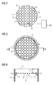
- An arrangement of the Bragg gratings with good resolution distributed in the exhaust duct 2 can be achieved by means of different optical waveguide and tubular structures. Examples are in the FIGS. 2 to 6 shown, wherein for ease of illustration of the sensor unit 11 each only the optical waveguide structure 6 and the Bragg gratings 5 are shown, the associated tubes are omitted.
- the optical waveguide structure 6 may be formed by a single optical waveguide 7 which alternately extends from one side of the exhaust duct 2 to an opposite side and thus forms an optical waveguide network 17.
- the optical waveguide network 17 preferably has meshes 13 of the same size. Between two mesh nodes in each case exactly one Bragg grating 5 is arranged.
- the optical waveguide network 17 has meshes 13 with a mesh size W, where the following applies to the mesh width W: D * / 3>W> D * / 10, where D * is the diameter of the chimney 3 or exhaust gas channel 2 in the region of the optical waveguide network 17.
- optical waveguide structure 6, for example, but also consist of a single or multiple optical waveguides with a circular or spiral course or of several intersecting optical waveguide sections.
- two adjacent parallel tubes each with an optical waveguide contained therein or single tube with two parallel optical waveguides may be present.
- the sensor unit 11 may be bordered by a frame 14 which is fastened by means of fastening elements 15 with a distance d from the outlet 12 of the exhaust gas in the interior of the exhaust passage 2.
- the tubes of the sensor unit 11 are electrically secured in the frame 14, insulated from the frame 14.
- the frame 14 itself is connected to the chimney 3 or exhaust gas channel 2.
- the frame 14 may also be held in the interior of the exhaust duct 2 by a support 16 fixed to the end of the exhaust duct 2 or chimney 3.
- each one sensor unit 11 may be present for each of the exhaust pipes 50.
- Each sensor unit 11 can then each be assigned its own measuring and evaluation unit 20, or all sensor units 11 is associated with a common measuring and evaluation unit 20.
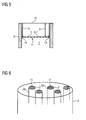
- the distance d of the sensor unit 11 from the outlet 12 of the exhaust gas can according to FIG. 7 be achieved at least partially by the fact that the sensor unit 11 includes an exhaust port 31 which is fixedly connected to the frame 14 and - as in FIG. 8 shown - is placed together with the frame 14 on the exhaust duct 2 and 3 chimney.
- the frame 14 is - as in FIG. 9 by way of example for the embodiment of the sensor unit 11 according to FIGS. 7 and 8 fastened via a fastening element 32 to the exhaust duct 2 or chimney, wherein the frame 14 is connected via a hinge 33 with the fastening element 32.
- the hinge 33 By means of the hinge 33, the frame 14 can then be tilted together with the exhaust port 31 from the outlet 12 of the chimney 3 from a horizontal position to a vertical position, so that the chimney 3 for inspection and cleaning measures accessible and easy maintenance of the sensor unit 11 is possible.
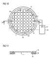
- the sensor unit 11 advantageously comprises a cleaning device 34 for cleaning the outer surface of the tubes 8 of the sensor unit 11.
- the cleaning device 34 comprises a plurality of compressed air nozzles 35 arranged in the frame 14, which are distributed uniformly over the circumference of the frame 14 and via a compressed air line 36 are connected to a compressed air source 37, which is arranged in the measuring and evaluation unit 20 and is controlled for example by the signal processing device 23.
- the surface of the tube 8 can also be cleaned by a surge in the tube 8, which has a short-term strong increase in temperature of the tube result, or be cleaned mechanically with the help of brushes. Contamination or deposition can be derived by the signal processing device 23 via the relationship between the fed-in electrical heating power and the measured temperature of the Bragg gratings without passing exhaust gas.
- exhaust-gas-generating device 1 in the form of a ship comprises an exhaust gas generator 40 (for example, an internal combustion engine or a steam turbine plant), which drives a propeller 42 via a propeller shaft 41.
- the exhaust gases of the exhaust gas generator 40 are supplied to an exhaust gas purification device 43 and the cleaned exhaust gases are discharged via a chimney 3 with an exhaust gas duct contained therein to the environment.
- a sensor unit 11 of a device for exhaust gas volume determination is arranged.
- the associated measurement and evaluation unit 20 is located inside the ship and is connected via a fiber optic cable 45 and a power cable 46 to the sensor unit 11.
- the measuring and evaluation unit 20 may be integrated, for example, in a higher-level automation system of the ship.
- a control and / or regulating device 48 for the exhaust gas generator 40 is coupled to the measuring and evaluation unit 20 via a data connection, in this case a data network 47, and receives therefrom measured values for the exhaust gas volume, the exhaust gas temperature and / or the pollutant emission.
- the control and / or regulating device 48 is designed such that it controls or regulates the operation of the exhaust gas generator 40 as a function of the determined exhaust gas volume, the determined exhaust gas temperature and / or the determined pollutant emission and thus optimizes the operation of the exhaust gas generator 40.
- the exhaust gas generator 40 may be controlled or regulated to an operating point with a minimum exhaust gas volume and / or a minimum pollutant emission.
- a diagnostic and condition monitoring system 49 Connected to the data network is also a diagnostic and condition monitoring system 49, which also receives the exhaust gas volume, exhaust gas temperature and / or pollutant emissions readings.
- the diagnosis and condition monitoring system 49 stores the measured values, evaluates them and initiates countermeasures when limit values are exceeded. It is also possible to transmit the measured values via satellite communication to a remote monitoring center.
Landscapes
- Physics & Mathematics (AREA)
- General Physics & Mathematics (AREA)
- Engineering & Computer Science (AREA)
- Aviation & Aerospace Engineering (AREA)
- Fluid Mechanics (AREA)
- Investigating Or Analysing Materials By Optical Means (AREA)
Description
- Die Erfindung betrifft eine abgaserzeugende Einrichtung, insbesondere ein Schiff, mit einem Abgaskanal, vom dem Abgas der Einrichtung in eine Umgebung der Einrichtung austritt, und mit einer Vorrichtung zur Bestimmung eines durch den Abgaskanal an die Umgebung abgegebenen Abgasvolumens gemäß Patentanspruch 1.
- Große stationäre und mobile Einrichtungen, wie z.B. fossile Kraftwerke, Industrieanlagen oder auch Schiffe, tragen wesentlich mit dazu bei, durch Schadstoffausstoß (z.B. CO2) das Klima zu verändern und die Umwelt zu belasten. Es ist daher zu erwarten, dass in naher Zukunft das Abgasvolumen derartiger Einrichtungen ermittelt wird, um daraus über Emissionszertifikate eine Kontrolle der Emissionen zu erreichen.
- Hierzu ist es bereits bekannt, das Abgasvolumen indirekt anhand von Betriebsparametern der Anlage, wie z.B. von einem Brennstoffverbrauch, einer Brennstoffzusammensetzung, einer Verbrennungstemperatur, etc. zu ermitteln. Dabei werden üblicherweise von dem Hersteller oder Betreiber eines Abgaserzeugers (z.B. einer Verbrennungskraftmaschine oder einer Dampfturbinenanlage) der Einrichtung bereitgestellte Daten und Zusammenhänge zwischen den Betriebsparametern und dem Abgasvolumen zugrunde gelegt. Es besteht dabei jedoch keine Möglichkeit, auf neutralem, unabhängigem Wege die dadurch ermittelten Abgasvolumen zu verifizieren.
-
WO 2004/042326 A2 offenbart ein Messelement zur Bestimmung einer Strömungsgeschwindigkeit eines das Messelement umströmenden Fluids mit einem Leiter zum Führen einer elektromagnetischen Welle entlang seiner Längserstreckung und wenigstens einem zum Leiter benachbart angeordneten, elektrischen Heizelement, mittels welchem der Leiter mit Wärme beaufschlagbar ist. Dabei wird eine in den Leiter eingekoppelte elektromagnetische Welle entsprechend der von der Strömungsgeschwindigkeit des Fluids abhängigen Temperatur des Leiters beeinflusst. - Latka, I. et al: "Monitoring of inhomogeneous flow distributions using fibre-optic Bragg grating temperature sensor arrays", PROCEEDINGS OF SPIE - THE INTERNATIONAL SOCIETY FOR OPTICAL ENGINEERING - OPTICAL SENSING II, offenbart eine Messvorrichtung mit Faser-Bragg-Gitter-Sensoren zur Bestimmung einer inhomogenen Strömungsgeschwindigkeitsverteilung in einem strömenden Gas.
-
EP 1510656 A1 offenbart ein Verfahren und eine Vorrichtung zum Erkennen eines Betriebszustandes beim Betrieb einer Turbine, bei dem ein heißes Abgas durch ein Abgasgehäuse strömt und die Temperatur des Abgases im Abgasgehäuse zeitaufgelöst erfasst wird. Dabei werden mehrere Temperaturmesswerte des Abgases ortsaufgelöst erfasst. -
DE 19821956 A1 offenbart ein Verfahren zur quantitativen Analyse von Gasvolumina mittels Emissions- oder Absorptionsspektrometrie im ultravioletten, sichtbaren und infraroten Spektralbereich. Dabei werden geometrisch definierte und reproduzierbar verstellbare Beobachtungsebenen festgelegt, die jeweils senkrecht zur Längsachse eines Abgasstrahls ausgerichtet sind, und Messreihen mit spektralen Messungen durchgeführt, wobei die optische Achse eines Spektrometers immer in einer Beobachtungsebene liegt. - Ausgehend hiervon ist es Aufgabe vorliegender Erfindung, eine verbesserte abgaserzeugende Einrichtung anzugeben, bei der das Abgasvolumen mit hoher Genauigkeit ermittelbar ist, wobei die hierzu notwendige Vorrichtung auch bei schon bestehenden Einrichtungen mit geringem Aufwand nachrüstbar sein und sich durch eine hohe Wartungsfreundlichkeit auszeichnen soll.
- Die Lösung dieser Aufgabe gelingt durch eine Einrichtung gemäß Patentanspruch 1. Vorteilhafte Ausgestaltungen sind jeweils Gegenstand der Unteransprüche 2 bis 16.
- Eine erfindungsgemäße abgaserzeugende Einrichtung weist zur Bestimmung des Abgasvolumens eine Vorrichtung auf, die mehrere quer zur Strömungsrichtung eines Abgases am Ende des Abgaskanals an vorbestimmten Positionen verteilt angeordnete Bragg-Gitter umfasst, die in einer Lichtwellenleiterstruktur ausgebildet sind, die aus zumindest einem Lichtwellenleiter besteht, wobei benachbart zu diesen Bragg-Gittern entweder eine Heizeinrichtung angeordnet ist, mit der die Bragg-Gitter mit Wärme beaufschlagbar sind, oder eine Kühleinrichtung angeordnet ist, durch die die Bragg-Gitter mit Kälte beaufschlagbar sind.
- Wenn Licht in die Lichtwellenleiterstruktur eingekoppelt wird, wird dieses an den darin angeordneten Bragg-Gittern entgegen seiner ursprünglichen Ausbreitungsrichtung zurückgestreut. Das Spektrum des zurückgestreuten Lichts ist dabei abhängig von der Gitterkonstante des Gitters. Die Gitterkonstante ist wiederum abhängig von der Temperatur des Gitters. Werden nun die Bragg-Gitter durch die Heizeinrichtung erwärmt bzw. durch die Kühleinrichtung gekühlt, so wird ein Teil der Wärmeleistung bzw. der Kühlleistung durch ein an den Gittern vorbeiströmendes Abgas abgeführt. Der abgeführte Teil ist dabei umso größer, je größer die Strömungsgeschwindigkeit des Abgases ist. Durch das in dem Abgaskanal an den Bragg-Gittern vorbeiströmende Abgas wird somit die Temperatur der Bragg-Gitter beeinflusst, und zwar umso mehr, je größer die Strömungsgeschwindigkeit des Abgases ist. In Abhängigkeit von der Temperatur des Bragg-Gitters ändert sich jedoch auch die Gitterkonstante des Gitters. Das Spektrum des zurückgestreuten Lichts ist somit abhängig von der Strömungsgeschwindigkeit des Abgases an dem Bragg-Gitter. Aus der Strömungsgeschwindigkeit des Abgases und der von dem Abgas durchströmten Fläche kann wiederum das Volumen das an den Gittern vorbeiströmenden Abgases abgeleitet werden.
- Dabei ist jedoch zu beachten, dass in großen industriellen und mobilen Anlagen die Abgaskanäle eine sehr große Querschnittsfläche von bis zu mehreren Quadratmetern aufweisen können. Damit kann man nicht mehr voraussetzen, dass eine über den gesamten Querschnitt homogene Strömung des Abgases vorliegt. Eine punktuelle Messung wäre daher nicht hinreichend. Deshalb werden mehrere Bragg-Gitter an vorbestimmten Positionen quer zur Strömungsrichtung des Abgases, d.h. in einer Querschnittsfläche des Abgaskanals, verteilt angeordnet. Hierdurch ist eine verteilte Strömungsmessung des Abgases über die gesamte Querschnittsfläche des Abgaskanals möglich, wodurch eine hohe Genauigkeit bei der Bestimmung des Abgasvolumens auch bei inhomogenen Abgasströmungen erzielt werden kann. Da Lichtwellenleiter einen sehr geringen Durchmesser und folglich einen geringen Strömungswiderstand aufweisen, stellt die Lichtleiterstruktur für eine derartige verteilte Strömungsmessung einen vernachlässigbaren Strömungswiderstand für den Abgasstrom dar, so dass der Betrieb der Anlage durch die Abgasvolumenbestimmung nicht beeinflusst wird. Es kann somit auf direktem Wege, unabhängig von Hersteller- oder Betreiberinformationen und mit hoher Genauigkeit das Abgasvolumen bestimmt werden.
- Der zumindest eine Lichtwellenleiter ist dabei vorzugsweise durch eine Glasfaser gebildet, da sich diese durch hohe Beständigkeit gegenüber physikalischen und/oder chemischen Beanspruchungen auszeichnet und insbesondere eine hohe Temperaturbeständigkeit aufweist. Je nach Anwendungsfall kann der Lichtwellenleiter jedoch auch durch eine Kunststofffaser gebildet sein.
- Da die Lichtwellenleiterstruktur und die Heizeinrichtung bzw. Kühleinrichtung am Ende des Abgaskanals angeordnet sind, kann eine Nachrüstung mit geringem Aufwand auch bei schon bestehenden Einrichtungen erfolgen, da hierzu keine Eingriffe in den Innenbereich des Abgaskanals notwendig sind. Außerdem ist die Zugänglichkeit für Wartungsmaßnahmen gewährleistet.
- Erfindungsgemäß sind dabei die Lichtwellenleiterstruktur und die Heizeinrichtung oder Kühleinrichtung nicht direkt am Austritt des Abgases an die Umgebung, sondern mit einem Abstand davon angeordnet. Hierbei liegt die Erkenntnis zugrunde, dass die Abgase schon im Bereich kurz vor dem Austritt des Abgases an die Umgebung durch die an dem Austritt vorbeiströmende Umgebungsluft verwirbelt und somit von ihrer normalen Strömungsrichtung, die vorzugsweise senkrecht zur Lichtwellenleiterstruktur verläuft, abgelenkt werden. Außerdem können die Abgase hier bereits mit Abgasen aus anderen eng benachbarten Schornsteinen vermischt werden. Beide Effekte würden zu Ungenauigkeiten in der Messung des Abgasvolumens führen. Durch einen Abstand von dem Austritt kann sichergestellt werden, dass das Abgas unbeeinflusst die Lichtwellenleiterstruktur und die Heizeinrichtung oder Kühleinrichtung anströmt und nicht mit anderem Abgas vermischt wird, so dass eine hohe Genauigkeit in der Messung des Abgasvolumens erzielt werden kann.
- Vorzugweise gilt dabei für den Abstand: d > D/10, vorzugsweise D > d > D/10, wobei d der Abstand von dem Austritt und D der Durchmesser des Austritts ist. Hierdurch kann ein ausreichender Abstand für eine senkrechte, von anderen Abgasen unbeeinflusste Anströmung der Lichtwellenleiterstruktur durch das Abgas und zugleich eine gute Zugänglichkeit zur der Lichtwellenleiterstruktur am Ende des Abgaskanals erzielt werden.
- Der Abstand der Lichtwellenleiterstruktur und der Heizeinrichtung oder Kühleinrichtung von dem Austritt des Abgases kann durch deren Anordnung im Inneren des Abgaskanals gegeben sein.
- Alternativ und/oder ergänzend kann der Abstand auch zumindest teilweise durch einen Abgasstutzen gegeben sein, der zusätzlich auf den Abgaskanal aufgesetzt ist.
- Von Vorteil ist der Abgasstutzen dabei ein Bestandteil der Vorrichtung zur Bestimmung des Abgasvolumens.
- Gemäß einer besonders vorteilhaften Ausgestaltung ist der zumindest eine Lichtwellenleiter in einem Hohlraum eines steifen Trägerkörpers angeordnet, dessen Form den Verlauf des Lichtwellenleiters in dem Abgaskanal festlegt, wobei der Trägerkörper zugleich die Heizeinrichtung oder Kühleinrichtung bildet. Hierdurch ist eine große mechanische Stabilität und Schutz der Lichtwellenleiterstruktur vor aggressiven Abgasen gegeben, wobei sich diese Ausgestaltung auch durch eine besondere konstruktive Einfachheit auszeichnet, da der Trägerkörper auch gleich die Heizeinrichtung oder Kühleinrichtung bildet. Falls der Trägerkörper auch die Heizeinrichtung bildet, besteht er bevorzugt aus einem Metall-Röhrchen, welches durch einen elektrischen Stromfluss beheizt werden kann.
- Eine gute Verteilung der Bragg-Gitter für eine genaue Messung des Abgasvolumens bei gleichzeitig guter mechanischer Stabilität und geringem Strömungswiderstand für das Abgas ist auf konstruktiv einfache Weise dadurch möglich, dass die Lichtwellenleiterstruktur mehrere sich kreuzende Lichtwellenleiterabschnitte umfasst, durch die ein Lichtwellenleiternetz ausgebildet ist, wobei das Lichtwellenleiternetz Maschen mit einer Maschenweite aufweist, wobei für die Maschenweite vorzugsweise gilt: D*/3 > W > D*/10, wobei W die Maschenweite und D* der Durchmesser des Abgaskanals bzw. Abgasstutzens im Bereich des Lichtwellenleiternetzes ist. Das Lichtwellenleiternetz kann dabei auch durch einen einzigen Lichtwellenleiter ausgebildet sein. Grundsätzlich kann die Lichtwellenleiterstruktur aber auch anders ausgestaltet sein, z.B. kann sie einen spiralförmig oder kreisförmig verlaufenden Lichtwellenleiter aufweisen, in dem die Bragg-Gitter hintereinander angeordnet sind.
- Zur mechanisch stabilen Befestigung der Lichtwellenleiterstruktur und der Heizeinrichtung oder Kühleinrichtung sind diese bevorzugt von einem Rahmen eingefasst.
- Der Rahmen kann dann am Ende oder im Inneren des Abgaskanals an dem Abgaskanal befestigt sein. Alternativ kann der Rahmen von einer Halterung im Inneren des Abgaskanals gehalten sein, wobei die Halterung an dem Ende des Abgaskanals befestigt ist.
- Der Rahmen kann auch über ein Scharnier mit einem Befestigungselement verbunden sein, das an dem Abgaskanal befestigt ist. Mittels des Scharniers kann dann der Rahmen vom Auslass des Abgaskanals weggekippt werden, so dass der Abgaskanal für Prüfungs- und Reinigungsmaßnahmen zugänglich ist und eine einfache Wartung der Lichtwellenleiterstruktur und der Heizeinrichtung bzw. Kühleinrichtung möglich ist.
- Da sich an dem Trägerkörper im Laufe der Zeit Abgaspartikel ablagern können, umfasst die Vorrichtung zur Bestimmung des Abgasvolumens von Vorteil eine Reinigungsvorrichtung zur Reinigung einer äußeren Oberfläche der Lichtwellenleiterstruktur und/oder der Heizeinrichtung bzw. Kühleinrichtung.
- Für die Ermittlung von Messwerten zu den Strömungsgeschwindigkeiten an den Bragg-Gittern und die weiteren Auswertungen umfasst die Vorrichtung zur Bestimmung des Abgasvolumens bevorzugt zumindest eine Lichtquelle zur Einstrahlung von Licht in die Lichtwellenleiterstruktur und zumindest eine Signalverarbeitungseinrichtung, welche aus von Bragg-Gittern in der Lichtwellenleiterstruktur entgegen seiner ursprünglichen Ausbreitungsrichtung zurückgestreutem Licht die Strömungsgeschwindigkeit des Abgases entlang des Verlaufes der Lichtwellenleiterstruktur bestimmt und daraus das vorbeiströmende Abgasvolumen ableitet.
- Gemäß einer weiteren vorteilhaften Ausgestaltung ist die Heizeinrichtung bzw. die Kühleinrichtung für eine Messung der
- Abgastemperatur deaktivierbar. Aus den ermittelten Strömungsgeschwindigkeiten kann dann aus der Dichte des Abgases auch die Masse des Abgases bestimmt werden. Die Dichte entspricht in erster Näherung der Dichte von Luft, wobei allerdings die Temperaturabhängigkeit der Dichte berücksichtigt werden muss. Die Abgastemperatur bzw. eine Abgastemperaturverteilung kann jedoch sehr einfach ebenfalls anhand des Spektrums von an den Bragg-Gittern der Lichtwellenleiterstruktur zurückgestreuten Lichts bestimmt werden. Dies ist dadurch möglich, dass die Bragg-Gitter für eine vorgegebene Zeit nicht beheizt bzw. gekühlt werden, so dass sie die Temperatur des Abgases aufweisen.
- Gemäß einer weiteren vorteilhaften Ausgestaltung umfasst die abgaserzeugende Einrichtung zusätzlich noch zumindest einen Sensor zur Messung einer Konzentration eines Schadstoffes in dem Abgas und eine Auswerteinheit, die derart ausgebildet ist, dass sie anhand zumindest eines Messwerts für eine Konzentration eines Schadstoffes in dem Abgas und eines ermittelten Abgasvolumens eine Schadstoffemission der Anlage bestimmt.
- Gemäß einer besonders vorteilhaften Ausgestaltung umfasst die abgaserzeugende Einrichtung einen Abgaserzeuger (z.B. eine Verbrennungskraftmaschine oder eine Dampfturbinenanlage) mit einer Steuer- und/oder Regelungseinrichtung für diesen Abgaserzeuger, wobei die Steuer- und/oder Regelungseinrichtung derart ausgebildet ist, dass sie den Betrieb des Abgaserzeugers in Abhängigkeit von einem ermittelten Abgasvolumen, einer ermittelten Abgastemperatur und/oder einer ermittelten Schadstoffemission steuert bzw. regelt.
- Die Erfindung sowie weitere vorteilhafte Ausgestaltungen der Erfindung gemäß Merkmalen der Unteransprüche werden im Folgenden anhand von Ausführungsbeispielen in den Figuren näher erläutert; darin zeigen:
- FIG 1
- einen Abgaskanal mit einer Vorrichtung zur Bestimmung des Abgasvolumens,
- FIG 2
- eine Draufsicht auf eine als ein Netz ausgebildete Sensoreinheit,
- FIG 3
- eine Draufsicht auf die Sensoreinheit von
FIG 2 mit einem Rahmen, - FIG 4
- einen Schnitt entlang der Linie IV-IV der
FIG 3 , - FIG 5
- einen Schnitt durch eine mittels eines Halters befestigte Sensoreinheit,
- FIG 6
- einen Schornstein mit mehreren Abgasrohren und Sensoreinheiten,
- FIG 7
- eine Sensoreinheit mit einem Abgasstutzen,
- FIG 8
- eine Befestigung der Sensoreinheit von
FIG 7 am Ende eines Abgaskanals, - FIG 9
- eine aus einem Abgaskanal klappbare Sensoreinheit,
- FIG 10
- eine Sensoreinheit mit einer Reinigungsvorrichtung,
- FIG 11
- einen Schnitt entlang der Linie XI-XI der
FIG 10 , - FIG 12
- eine abgaserzeugende Einrichtung mit einem Abgaserzeuger und einer Steuer- und/oder Regelungseinrichtung.
-
FIG 1 zeigt in einem schematischen Schnitt einen Schornstein 3 einer nicht näher dargestellten abgaserzeugenden Einrichtung. Bei dieser Einrichtung kann es sich beispielsweise um eine große stationäre oder mobile Anlage, wie z.B. ein Kraftwerk, eine industriellen Anlage oder insbesondere um ein Schiff handeln. Der Schornstein 3 bildet einen Abgaskanal 2 aus. Dieser hat beispielsweise einen kreisförmigen Querschnitt. Es sind jedoch auch andere Querschnittsgeometrien des Abgaskanals (z.B. rechteckig, quadratisch, oval) denkbar. - Eine Vorrichtung 10 zur Bestimmung des durch den Abgaskanal 2 bzw. Schornstein 3 an eine Umgebung 18 der abgaserzeugenden Einrichtung abgegebenen Abgasvolumens umfasst eine Sensoreinheit 11, die am Ende des Abgaskanals 2 in dem Abgaskanal 2 angeordnet ist, und eine damit verbundene Mess- und Auswerteeinheit. Die Sensoreinheit 11 umfasst Bragg-Gitter 5, die in dem Abgaskanal 2 senkrecht zur Strömungsrichtung 4 des Abgases an vorbestimmten Positionen verteilt angeordnet in einer Lichtwellenleiterstruktur 6 ausgebildet bzw. eingearbeitet sind. Die Lichtwellenleiterstruktur 6 umfasst zur Vereinfachung der Darstellung hier nur einen geradlinig verlaufenden Lichtwellenleiter 7. In der Praxis umfasst sie jedoch vorzugsweise mehrere Lichtwellenleiter oder aber einen einzigen Lichtwellenleiter mit einem im Wesentlichen nichtlinearen Verlauf. Als Lichtwellenleiter wird vorzugsweise ein flexibles Glasfaserkabel eingesetzt.
- Der Lichtwellenleiter 7 ist in einem steifen Trägerkörper in Form eines dünnwandigen Röhrchens 8 aus Metall angeordnet, das senkrecht zur Strömungsrichtung des Abgases in dem Abgaskanal 2 angeordnet ist und dessen Form den Verlauf des Lichtwellenleiters 7 in dem Abgaskanal 2 festlegt. Der Lichtwellenleiter 7 ist dabei austauschbar in einem Hohlraum 9 des Röhrchens 8 angeordnet und durch das Röhrchen 8 vor unmittelbarem Kontakt mit dem Abgas geschützt.
- Wenn das Röhrchen 8 von einem Strom durchflossen wird, wärmt es sich auf und dient dabei als Heizeinrichtung für den Lichtwellenleiter 7. Durch das Röhrchen 8 wird der Lichtwellenleiter 7 gleichmäßig entlang seiner gesamten Länge auf eine Temperatur erwärmt, die beispielweise 50 - 100°C oberhalb der Temperatur des Abgases im Bereich der Sensoreinheit 11 liegt. Als Stahlröhrchen kommen beispielsweise Röhrchen aus einer hochtemperaturfesten Nickelbasislegierung (wie z.B. einer Inconel-Legierung) mit einem Außendurchmesser von 1.5 mm und einem Innendurchmesser von 0.5 mm zum Einsatz, die eine Temperaturfestigkeiten von 600°C und mehr aufweisen. Alternativ kann auch zur Erwärmung des Lichtwellenleiter 7 ein Hitzdraht in dem Röhrchen 8 angeordnet sein oder ein warmes Fluid durch das Röhrchen 8 strömen.
- Die Mess- und Auswerteeinheit 20 umfasst einen optischen Richtkoppler 21, eine Lichtquelle 22, eine Signalverarbeitungseinrichtung 23, eine Anzeigeeinheit 24 und eine Stromquelle 25. Der Lichtwellenleiter 7 ist über den optischen Richtkoppler 21 mit der Lichtquelle 22 und mit der Signalverarbeitungseinrichtung 23 verbunden. Der Richtkoppler 21 koppelt von der Lichtquelle 22 abgestrahltes Licht in den Lichtwellenleiter 7 ein und aus diesem zurückgestreutes Licht zu der Signalverarbeitungseinrichtung 23 aus. Der Signalverarbeitungseinrichtung 23 ist die Anzeigeeinheit 24 nachgeschaltet. Die Stromquelle 25 dient zur Stromversorgung des Röhrchens 8 und kann von der Signalverarbeitungseinrichtung 23 aus aktiviert und deaktiviert werden. Bei Aktivierung der Stromquelle 25 erwärmt das Röhrchen 8 den Lichtwellenleiter 7 mitsamt den Bragg-Gittern 5 gleichmäßig entlang seiner gesamten Länge.
- Die Bragg-Gitter 5 sind entlang des Lichtwellenleiters 7 in diesem an vorbestimmten Positionen mit gleichen oder untereinander verschiedenen Gitterperioden ausgebildet. Werden Bragg-Gitter 5 mit unterschiedlichen Gitterperioden eingesetzt, so wird bevorzugt eine breitbandig abstrahlende Lichtquelle 22 eingesetzt. Werden dagegen Bragg-Gitter mit gleichen oder im Wesentlichen gleichen Gitterperioden eingesetzt, so wird vorzugsweise eine gepulste, monochromatische Lichtquelle 22 eingesetzt. Die Bragg-Gitter 5 bestehen aus einer periodischen Folge von scheibenförmigen Bereichen, die einen von dem normalen Brechungsindex eines Kerns des Lichtwellenleiters 7 abweichenden Brechungsindex aufweisen.
- Wird in Bragg-Gitter 5 die beispielsweise unterschiedliche Gitterperioden aufweisen, Licht mit einer breitbandigen Verteilung der Intensität über der Wellenlänge eingestrahlt, dann wird ein geringer Teil des Lichtes an den Bragg-Gittern zurückgestreut, und zwar mit einer jeweils charakteristischen spektralen Intensitätsverteilung, die von der Gitterperiode des jeweiligen Gitters abhängt.
- Eine lokale Temperaturänderung des Lichtwellenleiters 7 im Bereich eines Bragg-Gitters 5 führt zu einer lokalen Längenexpansion oder -kontraktion und damit zu einer Änderung der Gitterperiode, was eine Verschiebung der spektralen Intensitätsverteilung des zurückgestreuten Lichtes zur Folge hat. Das Ausmaß dieser Verschiebung ist ein Maß für die Längenänderung und damit für die Temperaturänderung.
- Zur Abgasvolumenmessung mittels der Lichtwellenleiterstruktur wird zunächst eine Temperaturmessung der Bragg-Gitter 5 vorgenommen. Von der Temperatur der Bragg-Gitter 5 wird dann auf die Strömungsgeschwindigkeit des Abgases in dem Abgaskanal 2 und von dieser auf das Abgasvolumen geschlossen.
- Hierzu wird die Stromquelle 25 aktiviert und gibt elektrische Leistung an das Röhrchen 8 ab, was zu einer Erwärmung des Lichtwellenleiters 7 gegenüber seiner Umgebung und insbesondere auch gegenüber den Abgasen führt. Der Lichtwellenleiter 7 wird dabei auf eine Temperatur erwärmt, die - ohne das vorbeiströmende Abgas - über der Temperatur des an dem Lichtwellenleiter 7 vorbeiströmenden Abgases liegen würde. Über das an den Bragg-Gittern 5 vorbeiströmende Abgas wird jedoch ein Teil der von dem Röhrchen 8 ausgehenden Wärmeleistung abgeleitet, so dass sich die Bragg-Gitter 5 weniger erwärmen als ohne vorbeiströmendes Abgas. Es wird dabei umso mehr Wärmeleistung abgeleitet, je größer die Strömungsgeschwindigkeit des vorbeiströmenden kühleren Abgases ist.
- Die Signalverarbeitungseinrichtung 23 enthält einen Spektralanalysator zur Ermittlung der spektralen Verteilung des von den einzelnen Bragg-Gittern 5 zurück gestreuten Lichtes und eine Recheneinrichtung, welche das Ausmaß der jeweiligen Verschiebung gegenüber einer Referenzlage ermittelt und in eine Temperaturänderung gegenüber einer Referenztemperatur, bei der die spektrale Verteilung die Referenzlage hat, umrechnet. Dies geschieht für jedes einzelne Bragg-Gitter 5, so dass auf diese Weise die Verteilung der Temperatur entlang des gesamten Lichtwellenleiters 7 an den mit Bragg-Gittern 5 versehenen Stellen erhalten wird.
- Anhand dieser Temperaturen kann in der Signalverarbeitungseinrichtung 23 die Strömungsgeschwindigkeit des Abgases entlang des gesamten Lichtwellenleiters 7 an den mit Bragg-Gittern 5 versehenen Stellen bestimmt und daraus das durch den Abgaskanal 2 strömende Abgasvolumen abgeleitet und an der Anzeigeeinheit 24 ausgegeben werden. Die Gesamtquerschnittsfläche des Abgaskanals im Bereich der Lichtwellenleiterstruktur 6 ist dabei in Teilflächen um die verschiedenen Bragg-Gitter 5 herum aufgeteilt. Aus der mit einem Bragg-Gitter 5 einer Teilfläche gemessenen Strömungsgeschwindigkeit und der Fläche der Teilfläche kann das durch die Teilfläche strömende Abgasvolumen ermittelt werden. Die Summer der durch sämtliche Teilflächen strömenden Abgas(teil)volumina ergibt dann das vorbeiströmende Gesamtabgasvolumen. Die Genauigkeit kann dabei noch erhöht werden, wenn die Strömungsgeschwindigkeit zwischen den verschiedenen Messpunkten noch interpoliert wird und somit die Strömungsgeschwindigkeitsverteilung über den Teilflächen berücksichtigt wird. Es erfolgt somit keine punktuelle, sondern eine über die gesamte Strömungsquerschnittsfläche verteilte Strömungsmessung. Diese ermöglicht auch bei Querschnittsflächen des Abgaskanals 2 von mehreren Quadratmetern eine hohe Genauigkeit bei der Abgasvolumenbestimmung, ohne dass es zu einer nennenswerten Veränderung des Strömungswiderstandes in dem Abgaskanal 2 kommt. Bei kleinen Querschnittsflächen des Abgaskanals 2 kann dagegen auch bereits ein einziges Bragg-Gitter zu Abgasvolumenbestimmung ausreichend sein, d.h. es ist dann bereits ein einziger Lichtwellenleiter mit nur einem einzigen Bragg-Gitter zur Abgasvolumenbestimmung ausreichend.
- Bei Verwendung von Bragg-Gittern mit gleicher oder im Wesentlichen gleicher Gitterperiode weist die Signalverarbeitungsvorrichtung 23 zusätzlich eine Auswerteelektronik auf, welche die Laufzeit des rückgestreuten Lichts mit veränderter spektraler Intensitätsverteilung erfasst und auswertet. Um eine zeitaufgelöste Messung zu realisieren, kann auf gängige OTDR (Optical Time Domain Reflectometry) - Technik zurückgegriffen werden, wie sie in der Nachrichtentechnik zur Qualitätsbeurteilung von Signalstrecken verwendet wird.
- Statt einer Heizeinrichtung in Form des Röhrchens 8 kann auch eine Kälteeinrichtung verwendet werden, durch die der Lichtwellenleiter 7 und die darin eingearbeiteten Bragg-Gitter 5 mit Kälte beaufschlagbar sind. Als Kältemittel kann beispielsweise ein durch das Röhrchen 8 strömendes Fluid zum Einsatz kommen. Die Bragg-Gitter 5 können dann auf eine Temperatur abgekühlt werden, die - ohne das vorbeiströmende Abgas - unterhalb der Temperatur des Abgases liegen würde. Über das an den Bragg-Gittern 5 vorbeiströmende Abgas wird jedoch ein Teil der von der Kälteeinrichtung 19 ausgehenden Kälteleistung abgeleitet. Es wird dabei umso mehr Kälteleistung abgeleitet, je größer die Strömungsgeschwindigkeit des vorbeiströmenden wärmeren Abgases ist. Auch auf diesem Weg kann anhand der an den Bragg-Gittern gemessenen Temperaturen die Strömungsgeschwindigkeiten bestimmt und daraus in der Signalverarbeitungseinrichtung 23 das Abgasvolumen abgeleitet werden.
- Besonders vorteilhaft umfasst die Sensoreinheit 11 noch einen Sensor 30 zur Bestimmung der Konzentration eines Schadstoffes, wie z.B. Co2, NOx oder Schwefel in den Abgasen. Der Sensor 30 ist ebenfalls mit der Signalverarbeitungsvorrichtung 23 verbunden. Die Signalverarbeitungsvorrichtung 23 dient als Auswerteeinheit, die anhand eines ermittelten Abgasvolumens und eines Messwerts für die Konzentration des Schadstoffes in dem Abgas eine Schadstoffemission der Anlage bestimmt und auf der Anzeigeeinheit 24 ausgibt. Auf diesem Weg kann mit geringem konstruktivem Aufwand eine Abgasemissionsmessung von stationären und mobilen Anlagen, insbesondere von Schiffen, erfolgen. Die Messung der Konzentration des Schadstoffes in dem Abgas kann entweder punktuell mittels handelsüblicher Messgeräte oder verteilt (z.B. über Laser-Absorptions-Spektroskopie) erfolgen. Der Sensor 30 ist in Strömungsrichtung des Abgases vor der Sensoreinheit 11 angeordnet, so dass Verwirbelungen und Abgasvermischungen im Bereich des Austritts 12 keine Auswirkungen auf die Messergebisse haben.
- Vorteilhaft ist es, wenn die von dem Röhrchen 8 abzugebende Wärmeleistung einstellbar ist. Die Wärmeleistung kann in diesem Fall an die Abgastemperatur so angepasst werden, dass sich in dem Lichtwellenleiter 7 von der Signalverarbeitungseinrichtung 23 sicher detektierbare Temperaturunterschiede einstellen, ohne dass ein unnötiges Übermaß an elektrischer Leistung umgesetzt wird. Die Einstellung kann automatisch erfolgen, indem die von der Stromquelle 25 in die Röhrchen eingespeiste Leistung gesteuert durch die Signalverarbeitungseinrichtung 23 ausgehend von einem relativ niedrigen Ausgangswert so lange schrittweise erhöht wird, bis die Signalverarbeitungseinrichtung 23 entlang des Lichtwellenleiters 7 eindeutige Temperaturunterschiede feststellt.
- Die Auflösung und somit Genauigkeit der Abgasvolumenmessung wird durch die Anzahl der Bragg-Gitter 5 pro Flächeneinheit des Abgaskanals 2 und die Positionen der Bragg-Gitter 5 entlang des Lichtwellenleiters 7 vorgegeben und ist durch eine geeignete Auslegung an die Erfordernisse des jeweiligen Einsatzfalles anpassbar.
- Zusätzlich kann aus den ermittelten Strömungsgeschwindigkeiten auch die Masse des Abgases bestimmt werden. Hierzu muss nur die Dichte des Abgases bestimmt werden. Diese Dichte entspricht in erster Näherung der Dichte von Luft, wobei allerdings die Temperaturabhängigkeit der Dichte berücksichtigt werden muss. Die Abgastemperatur bzw. eine Abgastemperaturverteilung kann sehr einfach ebenfalls anhand des Spektrums des an den Bragg-Gittern 5 der Lichtwellenleiterstruktur 6 zurückgestreuten Lichts bestimmt werden. Dies ist dadurch möglich, dass die Bragg-Gitter 5 für eine vorgegebene Zeit nicht beheizt bzw. gekühlt werden, so dass sie die Temperatur des Abgases aufweisen. Die Signalverarbeitungseinrichtung 23 deaktiviert hierzu für eine vorgegebene Zeit die Stromquelle 25 für das Beheizen des Röhrchens 8.
- Die Sensoreinheit 11 ist mit einem Abstand d von einem Austritt 12 des Abgases in die Umgebung 18 der Einrichtung 1 in dem Abgaskanal 2 angeordnet. Für den Abstand d gilt: D > d > D/10, wobei D der maximale Durchmesser des Austritts 12 ist.
- Die Mess- und Auswerteeinheit 20 kann im Bereich des Endes des Abgaskanals 2 außerhalb des Abgaskanals 2 angeordnet oder beispielsweise auch am Fuß des Schornsteins 3 oder in einer Automatisierungszentrale der abgaserzeugenden Einrichtung angeordnet und über Kabel mit der Sensoreinheit verbunden sein.
- Eine im Abgaskanal 2 verteilte Anordnung der Bragg-Gitter mit guter Auflösung kann durch unterschiedliche Lichtwellenleiter- und Röhrchenstrukturen erzielt werden. Beispiele hierfür sind in den
FIG 2 bis 6 dargestellt, wobei zur Vereinfachung der Darstellung von der Sensoreinheit 11 jeweils nur die Lichtwellenleiterstruktur 6 und die Bragg-Gitter 5 dargestellt sind, die zugehörigen Röhrchen jedoch weggelassen sind. - Gemäß
FIG 2 kann die Lichtwellenleiterstruktur 6 durch einen einzigen Lichtwellenleiter 7 ausgebildet sein, der abwechselnd von einer Seite des Abgaskanals 2 zu einer gegenüberliegenden Seite verläuft und somit ein Lichtwellenleiternetz 17 ausbildet. Das Lichtwellenleiternetz 17 weist vorzugsweise Maschen 13 jeweils gleicher Größe auf. Zwischen zwei Maschenknoten ist jeweils genau ein Bragg-Gitter 5 angeordnet. Das Lichtwellenleiternetz 17 weist dabei Maschen 13 mit einer Maschenweite W auf, wobei für die Maschenweite W gilt: D*/3 > W > D*/10, wobei D* der Durchmesser des Schornsteins 3 bzw. Abgaskanals 2 im Bereich des Lichtwellenleiternetzes 17 ist. Hierdurch ist eine gute Auflösung bei der Messung bei einem nur geringen Strömungswiderstand durch das Abgas möglich. - Die Lichtwellenleiterstruktur. 6 kann beispielsweise aber auch aus einem einzigen oder mehreren Lichtwellenleitern mit kreisförmigem oder spiralförmigem Verlauf oder aus mehreren sich kreuzenden Lichtwellenleiterabschnitten bestehen.
- Zur Erhöhung der Redundanz können statt eines einzigen Röhrchens mit einem einzigen darin enthaltenen Lichtwellenleiter auch zwei benachbart parallel verlaufende Röhrchen mit jeweils einem darin enthaltenen Lichtwellenleiter oder einziges Röhrchen mit zwei parallel darin verlaufenden Lichtwellenleitern vorhanden sein.
- Wie in
FIG 3 und 4 dargestellt kann die Sensoreinheit 11 von einem Rahmen 14 eingefasst sein, der mittels Befestigungselementen 15 mit einem Abstand d von dem Austritt 12 des Abgases im Inneren des Abgaskanals 2 befestigt ist. Bevorzugt sind die Röhrchen der Sensoreinheit 11 elektrisch von dem Rahmen 14 isoliert in dem Rahmen 14 befestigt. Der Rahmen 14 selbst ist dagegen leitende mit dem Schornstein 3 bzw. Abgaskanal 2 verbunden. - Alternativ kann gemäß
FIG 5 der Rahmen 14 im Inneren des Abgaskanals 2 auch von einer Halterung 16 gehalten sein, die an dem Ende des Abgaskanals 2 bzw. Schornsteins 3 befestigt ist. - Falls ein Schornstein 3 - wie in
FIG 6 gezeigt - mehrere Abgasrohre 50 mit jeweils einem Abgaskanal 2 aufweist, kann jeweils eine Sensoreinheit 11 für jedes der Abgasrohre 50 vorhanden sein. Jeder Sensoreinheit 11 kann dann jeweils eine eigene Mess- und Auswerteeinheit 20 zugeordnet sein, oder sämtlichen Sensoreinheiten 11 ist eine gemeinsame Mess- und Auswerteeinheit 20 zugeordnet. - Der Abstand d der Sensoreinheit 11 von dem Austritt 12 des Abgases kann gemäß
FIG 7 zumindest teilweise auch dadurch erzielt werden, dass die Sensoreinheit 11 einen Abgasstutzen 31 umfasst, der fest mit dem Rahmen 14 verbunden ist und - wie inFIG 8 gezeigt - gemeinsam mit dem Rahmen 14 auf dem Abgaskanal 2 bzw. Schornstein 3 aufgesetzt ist. - Bevorzugt ist der Rahmen 14 - wie in
FIG 9 beispielhaft für die Ausgestaltung der Sensoreinheit 11 gemäßFIG 7 und 8 gezeigt - über ein Befestigungselement 32 an dem Abgaskanal 2 bzw. Schornstein befestigt, wobei der Rahmen 14 über ein Scharnier 33 mit dem Befestigungselement 32 verbunden ist. Mittels des Scharniers 33 kann dann der Rahmen 14 mitsamt Abgasstutzen 31 vom Auslass 12 des Schornsteins 3 von einer waagrechten Lage in eine vertikale Lage gekippt werden, so dass der Schornstein 3 für Prüfungs- und Reinigungsmaßnahmen zugänglich und eine einfache Wartung der Sensoreinheit 11 möglich ist. - Wie in
FIG 10 in einer Draufsicht und inFIG 11 in einem Schnitt entlang der Linie XI-XI vonFIG 10 gezeigt, umfasst die Sensoreinheit 11 von Vorteil eine Reinigungsvorrichtung 34 zur Reinigung der äußeren Oberfläche der Röhrchen 8 der Sensoreinheit 11. Die Reinigungsvorrichtung 34 umfasst mehrere in dem Rahmen 14 angeordnete Druckluftdüsen 35, die gleichmäßig über den Umfang des Rahmens 14 verteilt angeordnet und über eine Druckluftleitung 36 mit einer Druckluftquelle 37 verbunden sind, die in der Mess- und Auswerteeinheit 20 angeordnet ist und beispielsweise von der Signalverarbeitungseinrichtung 23 gesteuert wird. Durch einen Druckluftstoß können Abgaspartikel, die sich auf den Röhrchen der Sensoreinheit 11 im Laufe der Zeit, insbesondere im Bereich der Wände des Abgaskanals 2 bzw. Schornsteins 3, ablagern können, entfernt werden. Hierdurch kann eine Erhöhung des Wärmeübergangswiderstandes zwischen dem Abgas und den Bragg-Gittern durch an den Röhrchen abgelagerte Abgaspartikel und eine damit einhergehende Beeinflussung der Messergebnisse vermieden werden. Satt mit Druckluft kann die Oberfläche des Röhrchens 8 auch durch einen Stromstoß in dem Röhrchen 8, der eine kurzzeitige starke Temperaturerhöhung des Röhrchens zur Folge hat, oder mechanisch mit Hilfe von Bürsten gereinigt werden. Eine Verschmutzung oder Ablagerung kann durch die Signalverarbeitungseinrichtung 23 über den Zusammenhang zwischen eingespeister elektrischer Heizleistung und gemessener Temperatur der Bragg-Gitter ohne vorbeiströmendes Abgas abgeleitet werden. - Eine in
FIG 12 gezeigte abgaserzeugende Einrichtung 1 in Form eines Schiffes umfasst einen Abgaserzeuger 40 (z.B. eine Verbrennungskraftmaschine oder eine Dampfturbinenanlage), die über eine Propellerwelle 41 einen Propeller 42 antreibt. Die Abgase des Abgaserzeugers 40 werden einer Abgasreinigungsvorrichtung 43 zugeführt und die gereinigten Abgase über einen Schornstein 3 mit einem darin enthaltenen Abgaskanal an die Umgebung abgegeben. Am Ende des Schornsteins 3 ist eine Sensoreinheit 11 einer Vorrichtung zur Abgasvolumenbestimmung angeordnet. Die zugehörige Mess- und Auswerteeinheit 20 befindet sich im Inneren des Schiffes und ist über ein Glasfaserkabel 45 und ein Stromkabel 46 an die Sensoreinheit 11 angeschlossen. Die Mess- und Auswerteeinheit 20 kann beispielsweise in ein übergeordnetes Automatisierungssystem des Schiffes integriert sein. - Eine Steuer- und/oder Regelungseinrichtung 48 für den Abgaserzeuger 40 ist über eine Datenverbindung, hier einen Datennetzwerk 47, mit der Mess- und Auswerteeinheit 20 gekoppelt und empfängt von dieser Messwerte für das Abgasvolumen, die Abgastemperatur und/oder die Schadstoffemission. Die Steuer- und/oder Regelungseinrichtung 48 ist derart ausgebildet ist, dass sie den Betrieb des Abgaserzeugers 40 in Abhängigkeit von dem ermittelten Abgasvolumen, der ermittelten Abgastemperatur und/oder der ermittelten Schadstoffemission steuert bzw. regelt und somit den Betrieb des Abgaserzeuger 40 optimiert. Beispielsweise kann der Abgaserzeuger 40 auf einen Betriebspunkt mit minimalem Abgasvolumen und/oder minimaler Schadstoffemission gesteuert oder geregelt werden. An das Datennetzwerk ist außerdem ein Diagnose- und Zustandsüberwachungssystem 49 angeschlossen, das ebenfalls die Messwerte für das Abgasvolumen, die Abgastemperatur und/oder die Schadstoffemission empfängt. Das Diagnose- und Zustandsüberwachungssystem 49 speichert die Messwerte ab, wertet sie aus und leitet bei Überschreiten von Grenzwerten Gegenmaßnahmen ein. Auch eine Übertragung der Messwerte per Satellitenkommunikation an eine entfernte Überwachungszentrale ist möglich.
Claims (16)
- Abgaserzeugende Einrichtung (1), insbesondere Schiff, mit einem Abgaskanal (2), vom dem Abgas der Einrichtung (1) in eine Umgebung (18) der Einrichtung (1) austritt, und mit einer Vorrichtung (10) zur Bestimmung eines durch den Abgaskanal (2) an die Umgebung (18) abgegebenen Abgasvolumens, wobei die Vorrichtung (10) zur Bestimmung des Abgasvolumens- mehrere quer zur Strömungsrichtung (4) des Abgases am Ende des Abgaskanals (2) an vorbestimmten Positionen verteilt angeordnete Bragg-Gitter (5) und- eine Lichtwellenleiterstruktur (6), in der die Bragg-Gittern (5) ausgebildet sind, wobei die Lichtwellenleiterstruktur (6) aus zumindest einem Lichtwellenleiter (7) besteht,
umfasst,
gekennzeichnet durch- eine benachbart zu den Bragg-Gittern (5) angeordnete Heizeinrichtung (8), durch die die Bragg-Gitter (5) mit wärme beaufschlagbar sind, wobei eine von der Heizeinrichtung (8) abzugebende Wärmeleistung an die Abgastemperatur anpassbar ist, oder eine benachbart zu den Bragg-Gittern (5) angeordnete Kühleinrichtung, durch die die Bragg-Gitter (5) auf eine Temperatur unterhalb einer Abgastemperatur des Abgases abkühlbar sind, wobei- die Lichtwellenleiterstruktur (6) und die Heizeinrichtung (8) oder die Kühleinrichtung am Ende des Abgaskanals (2) mit einem Abstand (d) von einem Austritt (12) des Abgases in die Umgebung (18) der Einrichtung (1) im Inneren des Abgaskanals (2) angeordnet sind, wobei für den Abstand (d) d > D/10 gilt, wobei d der Abstand (d) von dem Austritt (12) und D der Durchmesser des Austritts (12) ist. - Einrichtung (1) nach Anspruch 1,
dadurch gekennzeichnet, dass für den Abstand (d) gilt: D > d. - Einrichtung (1) nach einem der vorhergehenden Ansprüche,
dadurch gekennzeichnet, dass die Bragg-Gitter (5) entlang wenigstens eines Lichtwellenleiters (7) untereinander verschiedene Gitterperioden aufweisen und mittels einer Lichtquelle (22) spektral breitbandiges Licht in diesen Lichtwellenleiter (7) einstrahlbar ist, oder dass die Bragg-Gitter (5) entlang wenigstens eines Lichtwellenleiters (7) gleiche Gitterperioden aufweisen, mittels einer Lichtquelle (22) gepulstes, monochromatisches Licht in diesen Lichtwellenleiter (7) einstrahlbar ist und mittels einer Signalverarbeitungsvorrichtung (23) eine Laufzeit des rückgestreuten Lichts erfassbar und auswertbar ist. - Einrichtung (1) nach einem der Ansprüche 1 bis 3,
dadurch gekennzeichnet, dass der Abstand (d) zumindest teilweise durch einen Abgasstutzen (31) gegeben ist, der zusätzlich auf den Abgaskanal (2) aufgesetzt ist. - Einrichtung (1) nach Anspruch 4,
dadurch gekennzeichnet, dass der Abgasstutzen (31) ein Bestandteil der Vorrichtung (10) zur Bestimmung des Abgasvolumens ist. - Einrichtung (1) nach einem der vorhergehenden Ansprüche, dadurch gekennzeichnet, dass der zumindest eine Lichtwellenleiter (7) in einem Hohlraum (9) eines steifen Trägerkörpers (8) angeordnet ist, dessen Form den Verlauf des Lichtwellenleiters (7) in dem Abgaskanal (2) festlegt, wobei der Trägerkörper (8) zugleich die Heizeinrichtung (8) oder Kühleinrichtung bildet.
- Einrichtung (1) nach einem der vorhergehenden Ansprüche, dadurch gekennzeichnet, dass die Lichtwellenleiterstruktur (6) sich kreuzende Lichtwellenleiterabschnitte (7a) aufweist, durch die ein Lichtwellenleiternetz (17) ausgebildet ist, wobei das Lichtwellenleiternetz (17) Maschen (13) mit einer Maschenweite W aufweist, wobei für die Maschenweite vorzugsweise gilt: D*/3 > W > D*/10, wobei W die Maschenweite und D* der Durchmesser des Abgaskanals (2) oder Abgasstutzens (31) im Bereich des Lichtwellenleiternetzes (17) ist.
- Einrichtung (1) nach einem der vorhergehenden Ansprüche, dadurch gekennzeichnet, dass die Lichtwellenleiterstruktur (6) und die Heizeinrichtung (8) oder Kühleinrichtung von einem Rahmen (14) eingefasst sind.
- Einrichtung (1) nach Anspruch 8,
dadurch gekennzeichnet, dass der Rahmen (14) am Ende oder im Inneren des Abgaskanals (2) an dem Abgaskanal (2) befestigt ist. - Einrichtung (1) nach Anspruch 8,
dadurch gekennzeichnet, dass der Rahmen (14) von einer Halterung (16) im Inneren des Abgaskanals (2) gehalten ist, wobei die Halterung (16) an dem Ende des Abgaskanals (2) befestigt ist. - Einrichtung (1) nach Anspruch 8 oder 9,
dadurch gekennzeichnet, dass der Rahmen (14) über ein Scharnier (33) mit einem Befestigungselement (32) verbunden ist, das an dem Abgaskanal (2) befestigt ist. - Einrichtung (1) nach einem der vorhergehenden Ansprüche, gekennzeichnet durch eine Reinigungsvorrichtung (34) zur Reinigung einer äußeren Oberfläche der Lichtwellenleiterstruktur (6) und/oder der Heizeinrichtung (8) bzw. Kühleinrichtung.
- Einrichtung (1) nach einem der der vorhergehenden Ansprüche,
gekennzeichnet durch zumindest eine Lichtquelle (22) zur Einstrahlung von Licht in die Lichtwellenleiterstruktur (6) und zumindest eine Signalverarbeitungseinrichtung (23), welche aus von Bragg-Gittern (5) in der Lichtwellenleiterstruktur (6) entgegen seiner ursprünglichen Ausbreitungsrichtung zurückgestreutem Licht eine Strömungsgeschwindigkeit des Abgases entlang des Verlaufes der Lichtwellenleiterstruktur (6)
bestimmt und daraus das durch den Abgaskanal (2) strömende Abgasvolumen ableitet. - Einrichtung (1) nach einem der der vorhergehenden Ansprüche, dadurch gekennzeichnet, dass die Heizeinrichtung(8) bzw. die Kühleinrichtung für eine Messung der Abgastemperatur deaktivierbar ist.
- Einrichtung (1) nach einem der vorhergehenden Ansprüche, gekennzeichnet durch zumindest einen Sensor (30) zur Messung einer Konzentration eines Schadstoffes in dem Abgas und eine Auswerteinheit, die derart ausgebildet ist, dass sie anhand zumindest eines Messwerts für eine Konzentration eines Schadstoffes in dem Abgas und eines ermittelten Abgasvolumens eine Schadstoffemission der Anlage bestimmt.
- Einrichtung (1) nach einem der vorhergehenden Ansprüche, dadurch gekennzeichnet, dass sie einen Abgaserzeuger (40) mit einer Steuer- und/oder Regelungseinrichtung (42) für diesen Abgaserzeuger (40) umfasst, wobei die Steuer- und/oder Regelungseinrichtung (42) derart ausgebildet ist, dass sie den Betrieb des Abgaserzeugers (40) in Abhängigkeit von einem ermittelten Abgasvolumen, einer ermittelten Abgastemperatur und/oder einer ermittelten Schadstoffemission steuert bzw. regelt.
Applications Claiming Priority (2)
| Application Number | Priority Date | Filing Date | Title |
|---|---|---|---|
| DE102009043345A DE102009043345A1 (de) | 2009-09-29 | 2009-09-29 | Abgaserzeugende Einrichtung, insbesondere Schiff, mit einer Abgasvolumenbestimmung |
| PCT/EP2010/064300 WO2011039153A1 (de) | 2009-09-29 | 2010-09-28 | Abgaserzeugende einrichtung, insbesondere schiff, mit einer abgasvolumenbestimmung |
Publications (2)
| Publication Number | Publication Date |
|---|---|
| EP2483643A1 EP2483643A1 (de) | 2012-08-08 |
| EP2483643B1 true EP2483643B1 (de) | 2013-08-14 |
Family
ID=43221998
Family Applications (1)
| Application Number | Title | Priority Date | Filing Date |
|---|---|---|---|
| EP10763343.0A Not-in-force EP2483643B1 (de) | 2009-09-29 | 2010-09-28 | Abgaserzeugende einrichtung, insbesondere schiff, mit einer abgasvolumenbestimmung |
Country Status (9)
| Country | Link |
|---|---|
| US (1) | US9157780B2 (de) |
| EP (1) | EP2483643B1 (de) |
| KR (1) | KR101332898B1 (de) |
| CN (1) | CN102575952B (de) |
| AU (1) | AU2010303084B2 (de) |
| DE (1) | DE102009043345A1 (de) |
| DK (1) | DK2483643T3 (de) |
| ES (1) | ES2430990T3 (de) |
| WO (1) | WO2011039153A1 (de) |
Families Citing this family (13)
| Publication number | Priority date | Publication date | Assignee | Title |
|---|---|---|---|---|
| CN102575953B (zh) * | 2009-09-29 | 2016-02-17 | 西门子公司 | 废气体积测定装置 |
| EP3033490A1 (de) * | 2013-12-27 | 2016-06-22 | Halliburton Energy Services, Inc. | Flussprofilmessung für ein mehrphasiges fluid |
| DE102015100213B3 (de) * | 2015-01-09 | 2016-05-25 | Helmholtz-Zentrum Dresden - Rossendorf E.V. | Anordnung zum Erfassen des Strömungsgeschwindigkeits-Feldes einer Fluidströmung in einem Strömungsquerschnitt |
| US10120102B2 (en) * | 2015-11-04 | 2018-11-06 | General Electric Company | Fluid sensor cable assembly, system, and method |
| DE102016125871A1 (de) * | 2016-12-29 | 2018-07-05 | Endress+Hauser Conducta Gmbh+Co. Kg | System zur Bestimmung und Überwachung zumindest einer Prozessgröße eines Mediums |
| DE102017120941B4 (de) | 2017-09-11 | 2025-04-30 | Endress + Hauser Wetzer Gmbh + Co. Kg | Thermisches Durchflussmessgerät und Verfahren zum Betreiben eines thermischen Durchflussmessgeräts |
| US11193854B2 (en) * | 2018-06-20 | 2021-12-07 | Rolls-Royce Plc | Estimating fluid parameter |
| CN108717046B (zh) * | 2018-06-27 | 2024-04-26 | 广东泓胜科技股份有限公司 | 一种遥感检测镜面自清洁装置 |
| DE102018215714A1 (de) * | 2018-09-14 | 2020-03-19 | Robert Bosch Gmbh | Sensor zur Bestimmung wenigstens eines Parameters eines durch einen Messkanal strömenden fluiden Mediums |
| CN109187358B (zh) * | 2018-09-17 | 2020-12-08 | 中国科学院武汉物理与数学研究所 | 分子旋光滤光船舶排放污染气体成像遥感监测装置及方法 |
| CN109405906B (zh) * | 2018-11-23 | 2024-08-06 | 宁波水表(集团)股份有限公司 | 一种流量计量装置以及流量计量方法 |
| CN110579250A (zh) * | 2019-09-17 | 2019-12-17 | 西北大学 | 一种基于低启动流光纤光栅流量传感器及其制备方法 |
| CN112413616B (zh) * | 2020-10-14 | 2022-11-18 | 湖北工业大学 | 一种高温锅炉自动温度场测量吹灰系统 |
Family Cites Families (15)
| Publication number | Priority date | Publication date | Assignee | Title |
|---|---|---|---|---|
| US5357795A (en) * | 1993-03-17 | 1994-10-25 | Djorup Robert Sonny | Anemometer transducer wind set |
| DE19821956A1 (de) * | 1998-05-16 | 1999-11-18 | Deutsch Zentr Luft & Raumfahrt | Verfahren zur quantitativen Analyse von Gasvolumina, insbesondere von Abgasen aus Verbrennungseinrichtungen oder -anlagen, sowie Einrichtungen zur Durchführung des Verfahrens |
| US5979423A (en) * | 1998-05-29 | 1999-11-09 | Ford Global Technologies, Inc. | Fiber-optic gas composition sensor for exhaust gases |
| DE10251701B4 (de) | 2002-11-06 | 2006-05-04 | Siemens Ag | Messelement zur Bestimmung einer Strömungsgeschwindigkeit |
| US6986276B2 (en) * | 2003-03-07 | 2006-01-17 | Weatherford/Lamb, Inc. | Deployable mandrel for downhole measurements |
| EP1510656A1 (de) | 2003-09-01 | 2005-03-02 | Siemens Aktiengesellschaft | Verfahren und Vorrichtung zum Erkennen eines Betriebszustandes einer Turbine |
| GB2416394B (en) * | 2004-07-17 | 2006-11-22 | Sensor Highway Ltd | Method and apparatus for measuring fluid properties |
| US7263882B2 (en) * | 2005-02-03 | 2007-09-04 | Integrated Sensing Systems, Inc. | Fluid system and method of assessing a property of a fluid flowing therein |
| DE102006012229B3 (de) | 2006-03-16 | 2007-06-14 | Siemens Ag | Strömungsmessvorrichtung zur Bestimmung einer Strömungsrichtung |
| US7336862B1 (en) * | 2007-03-22 | 2008-02-26 | General Electric Company | Fiber optic sensor for detecting multiple parameters in a harsh environment |
| DE102007019927B3 (de) * | 2007-04-27 | 2008-09-25 | Forschungszentrum Dresden - Rossendorf E.V. | Anordnung zur zweidimensionalen Messung des Geschwindigkeitsfeldes in Strömungen |
| US8280202B2 (en) * | 2009-05-14 | 2012-10-02 | General Electric Company | Fiber-optic dynamic sensing modules and methods |
| US8306373B2 (en) * | 2009-05-15 | 2012-11-06 | General Electric Company | Fiber Bragg grating sensing package and system for gas turbine temperature measurement |
| CN102575953B (zh) * | 2009-09-29 | 2016-02-17 | 西门子公司 | 废气体积测定装置 |
| US9116055B2 (en) * | 2012-09-05 | 2015-08-25 | Siemens Energy, Inc | Combustion turbine flashback sensing system employing fiber Bragg grating sensors |
-
2009
- 2009-09-29 DE DE102009043345A patent/DE102009043345A1/de not_active Ceased
-
2010
- 2010-09-28 DK DK10763343.0T patent/DK2483643T3/da active
- 2010-09-28 AU AU2010303084A patent/AU2010303084B2/en not_active Ceased
- 2010-09-28 EP EP10763343.0A patent/EP2483643B1/de not_active Not-in-force
- 2010-09-28 US US13/498,638 patent/US9157780B2/en not_active Expired - Fee Related
- 2010-09-28 CN CN201080043616.7A patent/CN102575952B/zh not_active Expired - Fee Related
- 2010-09-28 KR KR1020127010836A patent/KR101332898B1/ko not_active Expired - Fee Related
- 2010-09-28 WO PCT/EP2010/064300 patent/WO2011039153A1/de not_active Ceased
- 2010-09-28 ES ES10763343T patent/ES2430990T3/es active Active
Also Published As
| Publication number | Publication date |
|---|---|
| US9157780B2 (en) | 2015-10-13 |
| AU2010303084B2 (en) | 2013-06-06 |
| AU2010303084A1 (en) | 2012-04-05 |
| EP2483643A1 (de) | 2012-08-08 |
| CN102575952A (zh) | 2012-07-11 |
| DE102009043345A1 (de) | 2011-05-12 |
| KR101332898B1 (ko) | 2013-11-26 |
| ES2430990T3 (es) | 2013-11-22 |
| WO2011039153A1 (de) | 2011-04-07 |
| CN102575952B (zh) | 2016-03-16 |
| DK2483643T3 (da) | 2013-11-25 |
| US20120186570A1 (en) | 2012-07-26 |
| KR20120056892A (ko) | 2012-06-04 |
Similar Documents
| Publication | Publication Date | Title |
|---|---|---|
| EP2483643B1 (de) | Abgaserzeugende einrichtung, insbesondere schiff, mit einer abgasvolumenbestimmung | |
| EP2483642B1 (de) | Abgasvolumenbestimmungsvorrichtung | |
| DE102014100691B3 (de) | Vorrichtung zur Bestimmung der Konzentration zumindest eines Gases in einem Probengasstrom mittels Infrarotabsorptionsspektroskopie | |
| EP2574918A1 (de) | Mikrothermisches Verfahren und Sensor zur Bestimmung physikalischer Gaseigenschaften | |
| DE102010040285A1 (de) | Thermisches Durchflussmessgerät | |
| DE69919853T2 (de) | Vorrichtung und verfahren zur unmittelbaren messung des heizwertes eines brennbaren gases | |
| DE3148314A1 (de) | "vorrichtung zur temperaturmessung von koksofenkammerwaenden" | |
| DE102009045958A1 (de) | Thermisches Durchflussmessgerät | |
| EP3270045B1 (de) | Anordnung zum messen von gaskonzentrationen | |
| EP2215434B1 (de) | Sensoranordnung zur bestimmung eines parameters eines fluiden mediums | |
| DE202015001501U1 (de) | Versuchsgerät zur Untersuchung der Wärmeübertragung bei erzwungener Konvektion | |
| DE102017117132A1 (de) | Messeinrichtung zur Feinstaubmessung in mindestens einem Luftvolumen für ein Fahrzeug, insbesondere für ein Kraftfahrzeug | |
| DE102006019723B4 (de) | Messsondensystem, Anordnung und Verfahren zur Erfassung von Abgasparametern stromabwärts einer Gasturbine | |
| DE102006005012A1 (de) | Vorrichtung mit Fluidverteiler und Messwerterfassung sowie Verfahren zum Betrieb eines mit Rauchgas durchströmten Kessels | |
| EP1397650B1 (de) | Verfahren und vorrichtung zur diagnostik und überwachung eines unfokussierten laserstrahles von hochleistungs-laseranlagen | |
| WO2023232554A1 (de) | Verfahren zur messung eines massendurchflusses eines gasförmigen mediums | |
| DE102017102046B4 (de) | Entnahmesonde und Verfahren zur Entnahme von Abgas | |
| EP3365659A1 (de) | Infrarot-messvorrichtung | |
| DE102016214854B4 (de) | Verfahren und Vorrichtung zur Charakterisierung von Ablagerungen | |
| EP0053227A1 (de) | Vorrichtung zur Temperaturmessung von Koksofenkammerwänden | |
| DE3515433A1 (de) | Optisches gasdensitometer | |
| WO2012019951A1 (de) | Ofen, insbesondere tunnelofen, einer metallurgischen anlage und verfahren zur messung von temperaturen und stoffkonzentrationen in der ofenluft in dem ofen | |
| DE102013205848B3 (de) | Optisches Temperatursensorsystem | |
| DE102011077723A1 (de) | Temperatursensoranordnung | |
| AT519720B1 (de) | Vorrichtung und Verfahren zur Überwachung von Verbrennungsvorgängen und/oder eines Zündprozesses |
Legal Events
| Date | Code | Title | Description |
|---|---|---|---|
| PUAI | Public reference made under article 153(3) epc to a published international application that has entered the european phase |
Free format text: ORIGINAL CODE: 0009012 |
|
| 17P | Request for examination filed |
Effective date: 20120314 |
|
| AK | Designated contracting states |
Kind code of ref document: A1 Designated state(s): AL AT BE BG CH CY CZ DE DK EE ES FI FR GB GR HR HU IE IS IT LI LT LU LV MC MK MT NL NO PL PT RO SE SI SK SM TR |
|
| DAX | Request for extension of the european patent (deleted) | ||
| GRAP | Despatch of communication of intention to grant a patent |
Free format text: ORIGINAL CODE: EPIDOSNIGR1 |
|
| RAP1 | Party data changed (applicant data changed or rights of an application transferred) |
Owner name: SIEMENS AKTIENGESELLSCHAFT |
|
| GRAS | Grant fee paid |
Free format text: ORIGINAL CODE: EPIDOSNIGR3 |
|
| GRAA | (expected) grant |
Free format text: ORIGINAL CODE: 0009210 |
|
| AK | Designated contracting states |
Kind code of ref document: B1 Designated state(s): AL AT BE BG CH CY CZ DE DK EE ES FI FR GB GR HR HU IE IS IT LI LT LU LV MC MK MT NL NO PL PT RO SE SI SK SM TR |
|
| REG | Reference to a national code |
Ref country code: GB Ref legal event code: FG4D Free format text: NOT ENGLISH |
|
| REG | Reference to a national code |
Ref country code: AT Ref legal event code: REF Ref document number: 627104 Country of ref document: AT Kind code of ref document: T Effective date: 20130815 Ref country code: CH Ref legal event code: EP |
|
| REG | Reference to a national code |
Ref country code: IE Ref legal event code: FG4D Free format text: LANGUAGE OF EP DOCUMENT: GERMAN |
|
| REG | Reference to a national code |
Ref country code: DE Ref legal event code: R096 Ref document number: 502010004400 Country of ref document: DE Effective date: 20131010 |
|
| REG | Reference to a national code |
Ref country code: ES Ref legal event code: FG2A Ref document number: 2430990 Country of ref document: ES Kind code of ref document: T3 Effective date: 20131122 |
|
| REG | Reference to a national code |
Ref country code: DK Ref legal event code: T3 Effective date: 20131118 |
|
| REG | Reference to a national code |
Ref country code: NO Ref legal event code: T2 Effective date: 20130814 |
|
| REG | Reference to a national code |
Ref country code: NL Ref legal event code: VDEP Effective date: 20130814 |
|
| REG | Reference to a national code |
Ref country code: LT Ref legal event code: MG4D |
|
| PG25 | Lapsed in a contracting state [announced via postgrant information from national office to epo] |
Ref country code: SE Free format text: LAPSE BECAUSE OF FAILURE TO SUBMIT A TRANSLATION OF THE DESCRIPTION OR TO PAY THE FEE WITHIN THE PRESCRIBED TIME-LIMIT Effective date: 20130814 Ref country code: LT Free format text: LAPSE BECAUSE OF FAILURE TO SUBMIT A TRANSLATION OF THE DESCRIPTION OR TO PAY THE FEE WITHIN THE PRESCRIBED TIME-LIMIT Effective date: 20130814 Ref country code: HR Free format text: LAPSE BECAUSE OF FAILURE TO SUBMIT A TRANSLATION OF THE DESCRIPTION OR TO PAY THE FEE WITHIN THE PRESCRIBED TIME-LIMIT Effective date: 20130814 Ref country code: IS Free format text: LAPSE BECAUSE OF FAILURE TO SUBMIT A TRANSLATION OF THE DESCRIPTION OR TO PAY THE FEE WITHIN THE PRESCRIBED TIME-LIMIT Effective date: 20131214 Ref country code: CY Free format text: LAPSE BECAUSE OF FAILURE TO SUBMIT A TRANSLATION OF THE DESCRIPTION OR TO PAY THE FEE WITHIN THE PRESCRIBED TIME-LIMIT Effective date: 20130904 Ref country code: PT Free format text: LAPSE BECAUSE OF FAILURE TO SUBMIT A TRANSLATION OF THE DESCRIPTION OR TO PAY THE FEE WITHIN THE PRESCRIBED TIME-LIMIT Effective date: 20131216 |
|
| PG25 | Lapsed in a contracting state [announced via postgrant information from national office to epo] |
Ref country code: LV Free format text: LAPSE BECAUSE OF FAILURE TO SUBMIT A TRANSLATION OF THE DESCRIPTION OR TO PAY THE FEE WITHIN THE PRESCRIBED TIME-LIMIT Effective date: 20130814 Ref country code: SI Free format text: LAPSE BECAUSE OF FAILURE TO SUBMIT A TRANSLATION OF THE DESCRIPTION OR TO PAY THE FEE WITHIN THE PRESCRIBED TIME-LIMIT Effective date: 20130814 Ref country code: PL Free format text: LAPSE BECAUSE OF FAILURE TO SUBMIT A TRANSLATION OF THE DESCRIPTION OR TO PAY THE FEE WITHIN THE PRESCRIBED TIME-LIMIT Effective date: 20130814 Ref country code: GR Free format text: LAPSE BECAUSE OF FAILURE TO SUBMIT A TRANSLATION OF THE DESCRIPTION OR TO PAY THE FEE WITHIN THE PRESCRIBED TIME-LIMIT Effective date: 20131115 |
|
| BERE | Be: lapsed |
Owner name: SIEMENS A.G. Effective date: 20130930 |
|
| PG25 | Lapsed in a contracting state [announced via postgrant information from national office to epo] |
Ref country code: CY Free format text: LAPSE BECAUSE OF FAILURE TO SUBMIT A TRANSLATION OF THE DESCRIPTION OR TO PAY THE FEE WITHIN THE PRESCRIBED TIME-LIMIT Effective date: 20130814 |
|
| PG25 | Lapsed in a contracting state [announced via postgrant information from national office to epo] |
Ref country code: RO Free format text: LAPSE BECAUSE OF FAILURE TO SUBMIT A TRANSLATION OF THE DESCRIPTION OR TO PAY THE FEE WITHIN THE PRESCRIBED TIME-LIMIT Effective date: 20130814 Ref country code: NL Free format text: LAPSE BECAUSE OF FAILURE TO SUBMIT A TRANSLATION OF THE DESCRIPTION OR TO PAY THE FEE WITHIN THE PRESCRIBED TIME-LIMIT Effective date: 20130814 Ref country code: SK Free format text: LAPSE BECAUSE OF FAILURE TO SUBMIT A TRANSLATION OF THE DESCRIPTION OR TO PAY THE FEE WITHIN THE PRESCRIBED TIME-LIMIT Effective date: 20130814 Ref country code: EE Free format text: LAPSE BECAUSE OF FAILURE TO SUBMIT A TRANSLATION OF THE DESCRIPTION OR TO PAY THE FEE WITHIN THE PRESCRIBED TIME-LIMIT Effective date: 20130814 Ref country code: CZ Free format text: LAPSE BECAUSE OF FAILURE TO SUBMIT A TRANSLATION OF THE DESCRIPTION OR TO PAY THE FEE WITHIN THE PRESCRIBED TIME-LIMIT Effective date: 20130814 |
|
| PG25 | Lapsed in a contracting state [announced via postgrant information from national office to epo] |
Ref country code: MC Free format text: LAPSE BECAUSE OF FAILURE TO SUBMIT A TRANSLATION OF THE DESCRIPTION OR TO PAY THE FEE WITHIN THE PRESCRIBED TIME-LIMIT Effective date: 20130814 |
|
| PLBE | No opposition filed within time limit |
Free format text: ORIGINAL CODE: 0009261 |
|
| STAA | Information on the status of an ep patent application or granted ep patent |
Free format text: STATUS: NO OPPOSITION FILED WITHIN TIME LIMIT |
|
| REG | Reference to a national code |
Ref country code: IE Ref legal event code: MM4A |
|
| 26N | No opposition filed |
Effective date: 20140515 |
|
| PG25 | Lapsed in a contracting state [announced via postgrant information from national office to epo] |
Ref country code: IE Free format text: LAPSE BECAUSE OF NON-PAYMENT OF DUE FEES Effective date: 20130928 Ref country code: BE Free format text: LAPSE BECAUSE OF NON-PAYMENT OF DUE FEES Effective date: 20130930 |
|
| REG | Reference to a national code |
Ref country code: DE Ref legal event code: R097 Ref document number: 502010004400 Country of ref document: DE Effective date: 20140515 |
|
| REG | Reference to a national code |
Ref country code: CH Ref legal event code: PL |
|
| GBPC | Gb: european patent ceased through non-payment of renewal fee |
Effective date: 20140928 |
|
| PG25 | Lapsed in a contracting state [announced via postgrant information from national office to epo] |
Ref country code: SM Free format text: LAPSE BECAUSE OF FAILURE TO SUBMIT A TRANSLATION OF THE DESCRIPTION OR TO PAY THE FEE WITHIN THE PRESCRIBED TIME-LIMIT Effective date: 20130814 |
|
| PG25 | Lapsed in a contracting state [announced via postgrant information from national office to epo] |
Ref country code: TR Free format text: LAPSE BECAUSE OF FAILURE TO SUBMIT A TRANSLATION OF THE DESCRIPTION OR TO PAY THE FEE WITHIN THE PRESCRIBED TIME-LIMIT Effective date: 20130814 Ref country code: MT Free format text: LAPSE BECAUSE OF FAILURE TO SUBMIT A TRANSLATION OF THE DESCRIPTION OR TO PAY THE FEE WITHIN THE PRESCRIBED TIME-LIMIT Effective date: 20130814 |
|
| PG25 | Lapsed in a contracting state [announced via postgrant information from national office to epo] |
Ref country code: LI Free format text: LAPSE BECAUSE OF NON-PAYMENT OF DUE FEES Effective date: 20140930 Ref country code: HU Free format text: LAPSE BECAUSE OF FAILURE TO SUBMIT A TRANSLATION OF THE DESCRIPTION OR TO PAY THE FEE WITHIN THE PRESCRIBED TIME-LIMIT; INVALID AB INITIO Effective date: 20100928 Ref country code: MK Free format text: LAPSE BECAUSE OF FAILURE TO SUBMIT A TRANSLATION OF THE DESCRIPTION OR TO PAY THE FEE WITHIN THE PRESCRIBED TIME-LIMIT Effective date: 20130814 Ref country code: CH Free format text: LAPSE BECAUSE OF NON-PAYMENT OF DUE FEES Effective date: 20140930 Ref country code: GB Free format text: LAPSE BECAUSE OF NON-PAYMENT OF DUE FEES Effective date: 20140928 Ref country code: LU Free format text: LAPSE BECAUSE OF NON-PAYMENT OF DUE FEES Effective date: 20130928 Ref country code: BG Free format text: LAPSE BECAUSE OF FAILURE TO SUBMIT A TRANSLATION OF THE DESCRIPTION OR TO PAY THE FEE WITHIN THE PRESCRIBED TIME-LIMIT Effective date: 20130814 |
|
| REG | Reference to a national code |
Ref country code: FR Ref legal event code: PLFP Year of fee payment: 7 |
|
| REG | Reference to a national code |
Ref country code: AT Ref legal event code: MM01 Ref document number: 627104 Country of ref document: AT Kind code of ref document: T Effective date: 20150928 |
|
| PGFP | Annual fee paid to national office [announced via postgrant information from national office to epo] |
Ref country code: DE Payment date: 20161121 Year of fee payment: 7 |
|
| PG25 | Lapsed in a contracting state [announced via postgrant information from national office to epo] |
Ref country code: AT Free format text: LAPSE BECAUSE OF NON-PAYMENT OF DUE FEES Effective date: 20150928 |
|
| PGFP | Annual fee paid to national office [announced via postgrant information from national office to epo] |
Ref country code: ES Payment date: 20161021 Year of fee payment: 7 |
|
| REG | Reference to a national code |
Ref country code: FR Ref legal event code: PLFP Year of fee payment: 8 |
|
| PGFP | Annual fee paid to national office [announced via postgrant information from national office to epo] |
Ref country code: FR Payment date: 20170918 Year of fee payment: 8 Ref country code: IT Payment date: 20170927 Year of fee payment: 8 Ref country code: NO Payment date: 20170914 Year of fee payment: 8 Ref country code: FI Payment date: 20170922 Year of fee payment: 8 |
|
| PGFP | Annual fee paid to national office [announced via postgrant information from national office to epo] |
Ref country code: DK Payment date: 20170921 Year of fee payment: 8 |
|
| REG | Reference to a national code |
Ref country code: DE Ref legal event code: R119 Ref document number: 502010004400 Country of ref document: DE |
|
| PG25 | Lapsed in a contracting state [announced via postgrant information from national office to epo] |
Ref country code: DE Free format text: LAPSE BECAUSE OF NON-PAYMENT OF DUE FEES Effective date: 20180404 |
|
| REG | Reference to a national code |
Ref country code: ES Ref legal event code: FD2A Effective date: 20181017 |
|
| PG25 | Lapsed in a contracting state [announced via postgrant information from national office to epo] |
Ref country code: AL Free format text: LAPSE BECAUSE OF FAILURE TO SUBMIT A TRANSLATION OF THE DESCRIPTION OR TO PAY THE FEE WITHIN THE PRESCRIBED TIME-LIMIT Effective date: 20130814 |
|
| PG25 | Lapsed in a contracting state [announced via postgrant information from national office to epo] |
Ref country code: ES Free format text: LAPSE BECAUSE OF NON-PAYMENT OF DUE FEES Effective date: 20170929 |
|
| REG | Reference to a national code |
Ref country code: NO Ref legal event code: MMEP |
|
| PG25 | Lapsed in a contracting state [announced via postgrant information from national office to epo] |
Ref country code: FI Free format text: LAPSE BECAUSE OF NON-PAYMENT OF DUE FEES Effective date: 20180928 |
|
| REG | Reference to a national code |
Ref country code: DK Ref legal event code: EBP Effective date: 20180930 |
|
| PG25 | Lapsed in a contracting state [announced via postgrant information from national office to epo] |
Ref country code: IT Free format text: LAPSE BECAUSE OF NON-PAYMENT OF DUE FEES Effective date: 20180928 Ref country code: NO Free format text: LAPSE BECAUSE OF NON-PAYMENT OF DUE FEES Effective date: 20180930 |
|
| PG25 | Lapsed in a contracting state [announced via postgrant information from national office to epo] |
Ref country code: FR Free format text: LAPSE BECAUSE OF NON-PAYMENT OF DUE FEES Effective date: 20180930 |
|
| PG25 | Lapsed in a contracting state [announced via postgrant information from national office to epo] |
Ref country code: DK Free format text: LAPSE BECAUSE OF NON-PAYMENT OF DUE FEES Effective date: 20180930 |