EP2483086B1 - Laufstreifenprofil eines fahrzeugreifens - Google Patents
Laufstreifenprofil eines fahrzeugreifens Download PDFInfo
- Publication number
- EP2483086B1 EP2483086B1 EP10752779.8A EP10752779A EP2483086B1 EP 2483086 B1 EP2483086 B1 EP 2483086B1 EP 10752779 A EP10752779 A EP 10752779A EP 2483086 B1 EP2483086 B1 EP 2483086B1
- Authority
- EP
- European Patent Office
- Prior art keywords
- channel
- elevation
- base
- wall
- channel wall
- Prior art date
- Legal status (The legal status is an assumption and is not a legal conclusion. Google has not performed a legal analysis and makes no representation as to the accuracy of the status listed.)
- Active
Links
Images


Classifications
-
- B—PERFORMING OPERATIONS; TRANSPORTING
- B60—VEHICLES IN GENERAL
- B60C—VEHICLE TYRES; TYRE INFLATION; TYRE CHANGING; CONNECTING VALVES TO INFLATABLE ELASTIC BODIES IN GENERAL; DEVICES OR ARRANGEMENTS RELATED TO TYRES
- B60C11/00—Tyre tread bands; Tread patterns; Anti-skid inserts
- B60C11/03—Tread patterns
- B60C11/04—Tread patterns in which the raised area of the pattern consists only of continuous circumferential ribs, e.g. zig-zag
- B60C11/042—Tread patterns in which the raised area of the pattern consists only of continuous circumferential ribs, e.g. zig-zag further characterised by the groove cross-section
- B60C11/045—Tread patterns in which the raised area of the pattern consists only of continuous circumferential ribs, e.g. zig-zag further characterised by the groove cross-section the groove walls having a three-dimensional shape
-
- B—PERFORMING OPERATIONS; TRANSPORTING
- B60—VEHICLES IN GENERAL
- B60C—VEHICLE TYRES; TYRE INFLATION; TYRE CHANGING; CONNECTING VALVES TO INFLATABLE ELASTIC BODIES IN GENERAL; DEVICES OR ARRANGEMENTS RELATED TO TYRES
- B60C11/00—Tyre tread bands; Tread patterns; Anti-skid inserts
- B60C11/03—Tread patterns
- B60C11/13—Tread patterns characterised by the groove cross-section, e.g. for buttressing or preventing stone-trapping
- B60C11/1353—Tread patterns characterised by the groove cross-section, e.g. for buttressing or preventing stone-trapping with special features of the groove bottom
- B60C2011/1361—Tread patterns characterised by the groove cross-section, e.g. for buttressing or preventing stone-trapping with special features of the groove bottom with protrusions extending from the groove bottom
Definitions
- the invention relates to a tread pattern of a vehicle tire - in particular pneumatic vehicle tire - with radially raised by grooves of spaced profile elements, wherein the grooves in the radial direction inwardly through its groove bottom and on both sides of the groove bottom in each case by a groove wall extending in the radial direction R from the groove bottom outwardly extending to the surface of the contact surface forming lateral surface are limited, wherein at least one groove extending over the circumference of the vehicle tire is formed, at least in a groove wall distributed over the circumference and spaced from each other in the radial direction R starting from the groove bottom radially outwardly extending, in the direction perpendicular to the groove wall in the groove extending in elevations formed in the groove wall are formed.
- Such pneumatic vehicle tires are known. It is known to form circumferential grooves of vehicle pneumatic tires for utility vehicles with pyramidal elevations of the sidewall, which serve as a stone deflector.
- the mutual pyramidal arrangements make it possible to hinder the penetration of larger stones into the interior of the groove and to make setting stones difficult. This makes it difficult for commercial vehicles, the catching of stones in the grooves of the tires and the risk of later uncontrolled ejection of the stones are reduced from the tread pattern.
- the groove bottom itself is not thereby protected against penetration of any nevertheless penetrated into the tread pattern, in particular smaller stones and foreign bodies.
- the introduction of force from the groove wall to the groove bottom takes place at the transition edge formed from elevation of the groove wall and groove bottom, whereby high pressure peaks arise precisely in the transition region between the elevations of the groove wall and the groove bottom.
- the transmission of force in the axial direction A across the tread profile can lead to crack formation in the groove bottom in the region of the transition between elevations of the groove wall and groove bottom due to the pressure peaks generated thereby.
- the invention has for its object in a simple manner to provide such a tread profile with improved durability.
- the object is achieved by forming a tread pattern of a vehicle tire - in particular pneumatic vehicle tire - with radially raised by grooves of spaced profile elements, wherein the grooves in the radial direction inwardly through their groove bottom and on both sides of the groove bottom in each case by a groove wall extending in the radial direction the groove bottom to the outside to the bottom contact surface forming lateral surface extends are limited, wherein at least one groove extending over the circumference of the vehicle tire is formed, distributed at least in a groove wall over the circumference and spaced from each other in the radial direction R starting from Rillengrund radially outwardly extending, in the direction perpendicular to the groove wall in the groove extending into elevations formed in the groove wall, in each case starting from a survey of the one Groove wall in the groove base at least a web-shaped elevation of the groove bottom is formed, which extends transversely to the extension direction of the groove bottom to the other groove wall and the other groove wall in the radially
- the formation causes a force dissipation from the groove wall via the elevation of the groove wall by means of the web-shaped stiffening takes place directly into the opposite groove wall and derived in the limited by this groove wall profile element becomes.
- the power is dissipated both via the stiffened by the web portion of the groove bottom itself and via the web above the groove bottom.
- the force directed in the direction of the groove bottom in the region of the elevation of the groove wall is specifically diverted both over the web in the direction of the adjacent profile element and distributed in the lower groove region on the web and groove bottom. This allows a uniform force distribution and targeted power dissipation in the profile.
- the risk of cracking in the groove bottom is reduced, the durability of the tire can be increased thereby.
- the risk of foreign bodies entering the groove bottom is reduced, whereby the durability can be further increased.
- the high durability of the groove base additionally improves the retreadability.
- a tread pattern according to the features of claim 2, wherein the web-shaped elevation of the groove bottom extending from a formed outside the groove wall in the groove corner of the base of the pyramid-like shape of the elevation of the groove wall to the other groove wall. This reliably protects the area of the corner which is particularly sensitive to cracking.
- a tread pattern according to the features of claim 4, wherein each of two other side surfaces which limit the survey towards the groove, a web-shaped elevation of the groove bottom extending to the other groove wall are formed. This allows an additional stiffening against torsion of the elevation of the groove wall around the radial in the region of the groove bottom and increases the protection against cracking caused thereby.
- the object is also achieved by the formation of a tread pattern according to the features of claim 5 , wherein the elevation of the groove wall has a conical-segment-like shape, wherein the base surface of the cone segment is formed in the groove bottom.
- a tread pattern according to the features of claim 6 wherein the web-shaped elevation is formed in its extension through the groove rectilinearly, including an angle ⁇ to the extension direction of the groove with 45 ° ⁇ ⁇ 135 °.
- a tread pattern according to the features of claim 7, wherein the web is formed with a web width b with (0,1c) ⁇ b ⁇ 5 (0,5c), where c is the measure of the maximum length extension of the elevation of the groove wall , measured in the direction of extension of the groove measured in the groove bottom.
- a tread pattern according to the features of claim 8 , wherein the web is formed with a measured in the radial direction R from the groove bottom web height h with (0.05 P T ) ⁇ h ⁇ (0.5 P T ), where P T represents the measure of the maximum profile depth of the groove measured in the radial direction.
- a tread pattern according to the features of claim 9, in which the web radially outwardly delimiting contour is rectilinearly formed across the groove, in which the transition between the web radially outwardly bounding the contour and the survey of the Groove wall with a radius of curvature R K is formed around a lying on the bridge of the groove wall and the groove facing side center of curvature M with R K ⁇ h curved rounded.
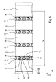
- FIGS. 1 to 5 show a tread pattern of a pneumatic vehicle tire for commercial vehicle tires with arranged in the axial direction A of the pneumatic vehicle tire, respectively over the entire circumference of the vehicle pneumatic tire and extending in the circumferential direction U aligned circumferential ribs 1, 2, 3 and 4.
- the circumferential ribs 1 and 2 are defined by a circumferential groove 5, the circumferential ribs 2 and 3 by a circumferential groove 6 and the circumferential ribs 3 and 4 by a circumferential groove 7 each in a known manner in the axial direction A from each other.
- the circumferential grooves 5, 6 and 7 extend over the entire circumference of the pneumatic vehicle tire and are aligned in the circumferential direction U.
- FIG. 1 show a tread pattern of a pneumatic vehicle tire for commercial vehicle tires with arranged in the axial direction A of the pneumatic vehicle tire, respectively over the entire circumference of the vehicle pneumatic tire and extending in the circumferential direction U aligned circumferential ribs
- the circumferential ribs 1 and 4 are each formed as a shoulder ribs.
- the ground contact surface of the pneumatic vehicle tire extends over an axial width T A from the extension region of the circumferential rib 1 into the extension region of the circumferential rib 4.
- the circumferential grooves 5, 6 and 7 are each formed in the same way. The further description is therefore limited, for the sake of simplicity, only to the formation of the circumferential groove 5.
- the circumferential groove 5 is bounded in the radial direction R inwardly with a groove bottom 8 extending over the entire circumference of the vehicle pneumatic tire and to the circumferential rib 1 with a groove wall 9 and the circumferential rib 2 with a groove wall 10, wherein the groove wall 9 in each case the flank facing the circumferential groove 5 the circumferential rib 1 and the groove wall 10 forms the peripheral groove 5 facing the circumferential groove 5 edge.
- the groove wall 9 extends in the radial direction R from the groove bottom 8 to the outside to to the circumferential rib 1 radially outwardly bounding, the ground contact surface forming lateral surface.
- the groove wall 10 extends in the radial direction R, starting from the groove bottom 8 to the outside to the circumferential rib 2 radially outwardly bounding, the ground contact surface forming lateral surface.
- the circumferential groove 5 is formed with a tread depth P T , which represents the maximum radial distance of the groove bottom 8 to the lateral contact surface forming lateral surface.
- the groove wall 9 intersects the circumferential rib 1 radially outwardly bounding lateral surface in a straight over the entire circumference of the vehicle pneumatic tire extending cutting line.
- the groove wall 10 intersects the circumferential rib 2 radially outwardly bounding lateral surface in a straight over the entire circumference of the vehicle pneumatic tire extending cutting line.
- the circumferential groove 5 is formed in the region of the radially outer circumferential surface over the entire circumference with a groove width B, which is the distance between the two straight lines of intersection of groove wall 9 and radially outer circumferential rib 1 limiting lateral surface and groove wall 10 and radially outer circumferential rib 2 limiting lateral surface represents.
- the groove walls 9 and 10 are each having a radially inner extension region 15, which extends from the groove bottom 8 radially outward over a radial extension height T 1 , and a radially outward adjoining R radially outer extension region 16, which over a radial extension height T 2 to the circumferential rib 1 and the circumferential rib 2 extends radially outwardly bounding lateral surface formed.
- T 1 is formed with T 1 ⁇ (0.5 P T ).
- T 1 (0.75P T ).
- the radially outer extension region 16 is flat and rectilinear in the illustrated embodiment over the entire circumference of the pneumatic vehicle tire running.
- a plurality of elevations 11 are respectively formed distributed over the circumference of the pneumatic vehicle tire.
- a plurality of such elevations 11 are distributed in the same way also over the circumference of the vehicle pneumatic tire formed, wherein the elevations 11 of the groove wall 9 and the elevations 11 of the groove wall 10 are arranged offset in the circumferential direction U of the vehicle pneumatic tire to each other in that in each case between two elevations 11 of the groove wall 9, an elevation 11 of the groove wall 10 and in each case between two elevations 11 of the groove wall 10, a survey 11 of the groove wall 9 is formed.
- the elevations 11 of the groove wall 9 and the elevations 11 of the groove wall 10 are formed in the same manner with respect to the respectively associated groove wall 9 and 10 and are therefore explained in more detail below for simplicity only in connection with a survey 11 of the groove wall 10.
- the elevation 11 extends from the otherwise rectilinear groove wall 10 extended over the circumference of the pneumatic vehicle tire into the circumferential groove 5.
- the elevation 11 extends in the circumferential direction U in the groove base 8 over a maximum extent c.
- the elevation 11 of the groove wall 10 forms with their circumferential grooves 5 toward the surfaces facing two triangular side surface 12 and 13.
- the triangular side surface 12 is triangular with the points V, T and S triangular Side surface 13 formed with the triangle points T, W and S.
- the triangular points V and W and T are respectively in the groove bottom 8.
- the triangular points V, W and S are respectively in the groove wall 5.
- the triangular side surface 12 with the triangle points V, T and S and the triangular side surface 13 with the triangular points T, W. and F thus describe two side surfaces of a tetrahedron whose base is formed between the triangle points V, T and W in the groove bottom 8 and the third side surface between the triangular points V, S and W formed in the groove wall 15.
- the point S forms the tip of the Tedraeder.
- the radially inner extension region 15 of the groove wall 10 extends in each case over the radial extent T 1, starting from the groove bottom 8 to the radial position of the tip S of the tetrahedron.
- the ridge-shaped elevation 14 binds the elevation 11 of the groove wall 10 to the groove wall 9.
- ⁇ 90 ° is selected.
- the ridge-shaped elevations 14 are formed in each case at their radially outwardly facing surface just with a ridge width b with (0.1 c) ⁇ b (0.5 c).
- the extension height h of the ridge-shaped elevation 14 measured in the radial direction R of the tire is formed with (0.05 P T ) ⁇ h ⁇ (0.5 P T ).
- the web-shaped elevation 14 is rectilinearly formed on its radially outer surface over the extension of the web 14 on the groove bottom 9 away.
- the transition to the elevation 11 is rounded off with a radius of curvature R K about a center of curvature M which is disposed on the side facing away from the web-shaped elevation 14 and the elevation 11 facing the groove 5 side. In this way, a smooth transition between the radially outer surface of the web 14 and the elevation 11 is formed.
- the radius of curvature R K is formed with R K ⁇ h to achieve the rounded transition.
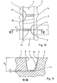
- FIGS. 6 to 9 show an alternative embodiment of the elevation 11 of the groove walls 9 and 10.
- the elevation 11 in this embodiment forms a pyramid-like shape with a pentagonal base of the pyramid, wherein the pentagonal base of the points F, G, W, T and V is formed and the top the pyramid is denoted by S.
- the points F, G and S lie in the groove wall 10.
- the points F, G, W, T, V of the base surface lie respectively in the groove bottom 8 of the circumferential groove 5, wherein the points W, T and V on that of the respective groove wall 10th lie to the opposite groove wall 9 facing side in groove bottom 8.
- the points G, S and F form a lying in the groove wall 10 triangular side surface of the pyramid.
- the points G, W and S form a triangular side surface 19 of the pyramid adjoining the groove wall 10.
- the points W, T and S form a further triangular side surface 13 of the pyramid adjoining the side surface 19.
- the points T, F, S form a triangular side surface 12 of the pyramid adjoining the side surface 13.
- the points V, F and S form the last, on the side surface 12 and the groove wall 10 subsequent triangular side surface 20 of the pyramid.
- the point T is the point farthest from the groove wall 10 of the pyramid.
- the point S forms the top of the pyramid.
- the web-shaped elevation 14 is also formed in this embodiment with the width b and with the height h.
- the maximum extent c of the radial elevation is formed in the illustrated embodiment in the groove wall 10 between the points G and F of the elevation 11.
- the definitions for the dimensioning of the height h and the width b of the web-shaped elevations 14 correspond to those in connection with the execution of the FIGS. 1 to 5 explained data and dimensions.
- FIGS. 6 to 8 show a further embodiment in which the extension direction of the web-shaped elevation 14 is oriented in each case perpendicular to the side edge of the side surface 12 and 13 respectively.
- Fig. 6 shows, in addition, another embodiment of the tread pattern with five adjacent in the axial direction A circumferential ribs 1, 2, 17, 3 and 4 and four circumferential grooves 5, 6, 18 and 7.
- Fig. 10 and Fig.1 show a further embodiment in which the elevations 11 each have a formed in the groove bottom 8 of the circumferential groove 5 circular segment-shaped sectional contour with the groove bottom 8, which forms the base of a cone segment with the apex S, wherein the apex S respectively in the associated groove wall 10 and 9 is located and the elevation 11 bounded radially outward.
- a web-shaped elevation 14 is in each case formed, which extends from the groove bottom 8 in the radial direction with the web height h of the width b and from the respective elevation 11 of the groove wall 10 and 9 through the circumferential groove 5 through to the opposite groove wall 9 and 10 extends and connects with the elevation 11 and thus binds.
Landscapes
- Engineering & Computer Science (AREA)
- Mechanical Engineering (AREA)
- Tires In General (AREA)
Priority Applications (1)
| Application Number | Priority Date | Filing Date | Title |
|---|---|---|---|
| PL10752779T PL2483086T3 (pl) | 2009-09-29 | 2010-09-06 | Profil bieżnika opony samochodowej |
Applications Claiming Priority (2)
| Application Number | Priority Date | Filing Date | Title |
|---|---|---|---|
| DE102009044123A DE102009044123A1 (de) | 2009-09-29 | 2009-09-29 | Laufstreifenprofil eines Fahrzeugluftreifens |
| PCT/EP2010/063018 WO2011039030A1 (de) | 2009-09-29 | 2010-09-06 | Laufstreifenprofil eines fahrzeugreifens |
Publications (2)
| Publication Number | Publication Date |
|---|---|
| EP2483086A1 EP2483086A1 (de) | 2012-08-08 |
| EP2483086B1 true EP2483086B1 (de) | 2013-05-15 |
Family
ID=42830100
Family Applications (1)
| Application Number | Title | Priority Date | Filing Date |
|---|---|---|---|
| EP10752779.8A Active EP2483086B1 (de) | 2009-09-29 | 2010-09-06 | Laufstreifenprofil eines fahrzeugreifens |
Country Status (6)
| Country | Link |
|---|---|
| EP (1) | EP2483086B1 (pl) |
| CN (1) | CN102548776B (pl) |
| DE (1) | DE102009044123A1 (pl) |
| ES (1) | ES2424672T3 (pl) |
| PL (1) | PL2483086T3 (pl) |
| WO (1) | WO2011039030A1 (pl) |
Families Citing this family (7)
| Publication number | Priority date | Publication date | Assignee | Title |
|---|---|---|---|---|
| FR3018223B1 (fr) | 2014-03-10 | 2017-11-03 | Michelin & Cie | Pneumatique comportant une texture a fort contraste dans une rainure |
| DE102014212352A1 (de) * | 2014-06-26 | 2015-12-31 | Continental Reifen Deutschland Gmbh | Fahrzeugluftreifen |
| DE102015205718A1 (de) * | 2015-03-30 | 2016-10-06 | Continental Reifen Deutschland Gmbh | Fahrzeugluftreifen |
| DE102017219532A1 (de) | 2017-11-03 | 2019-05-09 | Continental Reifen Deutschland Gmbh | Nutzfahrzeugreifen |
| JP7027873B2 (ja) * | 2017-12-20 | 2022-03-02 | 住友ゴム工業株式会社 | タイヤ |
| DE102021202966A1 (de) * | 2021-03-25 | 2022-09-29 | Continental Reifen Deutschland Gmbh | Fahrzeugluftreifen |
| JP7819525B2 (ja) * | 2022-02-25 | 2026-02-25 | 住友ゴム工業株式会社 | タイヤ |
Family Cites Families (3)
| Publication number | Priority date | Publication date | Assignee | Title |
|---|---|---|---|---|
| DE69616386T2 (de) * | 1996-07-22 | 2002-07-04 | The Goodyear Tire & Rubber Co., Akron | Reifenlauffläche mit durchflussnuten |
| US6415835B1 (en) * | 2000-06-08 | 2002-07-09 | The Goodyear Tire & Rubber Company | Pneumatic tire tread having groove with peaks and valleys |
| JP2002264614A (ja) * | 2001-03-13 | 2002-09-18 | Bridgestone Corp | タイヤ |
-
2009
- 2009-09-29 DE DE102009044123A patent/DE102009044123A1/de not_active Withdrawn
-
2010
- 2010-09-06 ES ES10752779T patent/ES2424672T3/es active Active
- 2010-09-06 CN CN201080043625.6A patent/CN102548776B/zh active Active
- 2010-09-06 WO PCT/EP2010/063018 patent/WO2011039030A1/de not_active Ceased
- 2010-09-06 PL PL10752779T patent/PL2483086T3/pl unknown
- 2010-09-06 EP EP10752779.8A patent/EP2483086B1/de active Active
Also Published As
| Publication number | Publication date |
|---|---|
| CN102548776B (zh) | 2014-09-17 |
| WO2011039030A1 (de) | 2011-04-07 |
| PL2483086T3 (pl) | 2013-10-31 |
| CN102548776A (zh) | 2012-07-04 |
| DE102009044123A1 (de) | 2011-03-31 |
| EP2483086A1 (de) | 2012-08-08 |
| ES2424672T3 (es) | 2013-10-07 |
Similar Documents
| Publication | Publication Date | Title |
|---|---|---|
| EP2483086B1 (de) | Laufstreifenprofil eines fahrzeugreifens | |
| EP2349746B1 (de) | Fahrzeugluftreifen | |
| EP3585626B1 (de) | Fahrzeugluftreifen | |
| EP3256334B1 (de) | Fahrzeugluftreifen | |
| EP3300926B1 (de) | Fahrzeugluftreifen | |
| DE102017211128A1 (de) | Fahrzeugluftreifen | |
| EP3009275B1 (de) | Fahrzeugluftreifen | |
| EP2595820B1 (de) | Laufstreifenprofil eines fahrzeugluftreifens | |
| EP2311656A1 (de) | Laufstreifenprofil eines Fahrzeugluftreifens | |
| EP3597449B1 (de) | Fahrzeugluftreifen | |
| EP2138327B1 (de) | Laufflächenprofil für einen Fahrzeugluftreifen | |
| EP1695844B1 (de) | Fahrzeugreifen mit einem Laufstreifenprofil | |
| EP3789213B1 (de) | Fahrzeugluftreifen | |
| EP2138329B1 (de) | Laufflächenprofil für einen Fahrzeugluftreifen | |
| EP3750723B1 (de) | Fahrzeugluftreifen | |
| EP3300925B1 (de) | Fahrzeugluftreifen | |
| EP2594416B1 (de) | Laufstreifen-Schulterbereich | |
| EP3100872A1 (de) | Fahrzeugluftreifen | |
| EP4003760B1 (de) | Fahrzeugluftreifen | |
| EP3418076B1 (de) | Fahrzeugluftreifen | |
| EP2138328A1 (de) | Fahrzeugluftreifen | |
| EP3224062B1 (de) | Fahrzeugluftreifen | |
| EP4360913B1 (de) | Fahrzeugluftreifen | |
| EP2402177B1 (de) | Fahrzeugluftreifen | |
| EP4061648B1 (de) | Nutzfahrzeugreifen |
Legal Events
| Date | Code | Title | Description |
|---|---|---|---|
| PUAI | Public reference made under article 153(3) epc to a published international application that has entered the european phase |
Free format text: ORIGINAL CODE: 0009012 |
|
| 17P | Request for examination filed |
Effective date: 20120502 |
|
| AK | Designated contracting states |
Kind code of ref document: A1 Designated state(s): AL AT BE BG CH CY CZ DE DK EE ES FI FR GB GR HR HU IE IS IT LI LT LU LV MC MK MT NL NO PL PT RO SE SI SK SM TR |
|
| DAX | Request for extension of the european patent (deleted) | ||
| GRAP | Despatch of communication of intention to grant a patent |
Free format text: ORIGINAL CODE: EPIDOSNIGR1 |
|
| GRAS | Grant fee paid |
Free format text: ORIGINAL CODE: EPIDOSNIGR3 |
|
| GRAA | (expected) grant |
Free format text: ORIGINAL CODE: 0009210 |
|
| AK | Designated contracting states |
Kind code of ref document: B1 Designated state(s): AL AT BE BG CH CY CZ DE DK EE ES FI FR GB GR HR HU IE IS IT LI LT LU LV MC MK MT NL NO PL PT RO SE SI SK SM TR |
|
| REG | Reference to a national code |
Ref country code: GB Ref legal event code: FG4D Free format text: NOT ENGLISH Ref country code: CH Ref legal event code: EP |
|
| REG | Reference to a national code |
Ref country code: AT Ref legal event code: REF Ref document number: 611935 Country of ref document: AT Kind code of ref document: T Effective date: 20130615 |
|
| REG | Reference to a national code |
Ref country code: IE Ref legal event code: FG4D Free format text: LANGUAGE OF EP DOCUMENT: GERMAN |
|
| REG | Reference to a national code |
Ref country code: DE Ref legal event code: R096 Ref document number: 502010003387 Country of ref document: DE Effective date: 20130718 |
|
| REG | Reference to a national code |
Ref country code: NL Ref legal event code: T3 |
|
| REG | Reference to a national code |
Ref country code: ES Ref legal event code: FG2A Ref document number: 2424672 Country of ref document: ES Kind code of ref document: T3 Effective date: 20131007 |
|
| REG | Reference to a national code |
Ref country code: LT Ref legal event code: MG4D |
|
| PG25 | Lapsed in a contracting state [announced via postgrant information from national office to epo] |
Ref country code: NO Free format text: LAPSE BECAUSE OF FAILURE TO SUBMIT A TRANSLATION OF THE DESCRIPTION OR TO PAY THE FEE WITHIN THE PRESCRIBED TIME-LIMIT Effective date: 20130815 Ref country code: IS Free format text: LAPSE BECAUSE OF FAILURE TO SUBMIT A TRANSLATION OF THE DESCRIPTION OR TO PAY THE FEE WITHIN THE PRESCRIBED TIME-LIMIT Effective date: 20130915 Ref country code: PT Free format text: LAPSE BECAUSE OF FAILURE TO SUBMIT A TRANSLATION OF THE DESCRIPTION OR TO PAY THE FEE WITHIN THE PRESCRIBED TIME-LIMIT Effective date: 20130916 Ref country code: LT Free format text: LAPSE BECAUSE OF FAILURE TO SUBMIT A TRANSLATION OF THE DESCRIPTION OR TO PAY THE FEE WITHIN THE PRESCRIBED TIME-LIMIT Effective date: 20130515 Ref country code: SI Free format text: LAPSE BECAUSE OF FAILURE TO SUBMIT A TRANSLATION OF THE DESCRIPTION OR TO PAY THE FEE WITHIN THE PRESCRIBED TIME-LIMIT Effective date: 20130515 Ref country code: SE Free format text: LAPSE BECAUSE OF FAILURE TO SUBMIT A TRANSLATION OF THE DESCRIPTION OR TO PAY THE FEE WITHIN THE PRESCRIBED TIME-LIMIT Effective date: 20130515 Ref country code: GR Free format text: LAPSE BECAUSE OF FAILURE TO SUBMIT A TRANSLATION OF THE DESCRIPTION OR TO PAY THE FEE WITHIN THE PRESCRIBED TIME-LIMIT Effective date: 20130816 Ref country code: FI Free format text: LAPSE BECAUSE OF FAILURE TO SUBMIT A TRANSLATION OF THE DESCRIPTION OR TO PAY THE FEE WITHIN THE PRESCRIBED TIME-LIMIT Effective date: 20130515 |
|
| REG | Reference to a national code |
Ref country code: PL Ref legal event code: T3 |
|
| PG25 | Lapsed in a contracting state [announced via postgrant information from national office to epo] |
Ref country code: HR Free format text: LAPSE BECAUSE OF FAILURE TO SUBMIT A TRANSLATION OF THE DESCRIPTION OR TO PAY THE FEE WITHIN THE PRESCRIBED TIME-LIMIT Effective date: 20130515 Ref country code: BG Free format text: LAPSE BECAUSE OF FAILURE TO SUBMIT A TRANSLATION OF THE DESCRIPTION OR TO PAY THE FEE WITHIN THE PRESCRIBED TIME-LIMIT Effective date: 20130815 |
|
| PG25 | Lapsed in a contracting state [announced via postgrant information from national office to epo] |
Ref country code: LV Free format text: LAPSE BECAUSE OF FAILURE TO SUBMIT A TRANSLATION OF THE DESCRIPTION OR TO PAY THE FEE WITHIN THE PRESCRIBED TIME-LIMIT Effective date: 20130515 |
|
| PG25 | Lapsed in a contracting state [announced via postgrant information from national office to epo] |
Ref country code: DK Free format text: LAPSE BECAUSE OF FAILURE TO SUBMIT A TRANSLATION OF THE DESCRIPTION OR TO PAY THE FEE WITHIN THE PRESCRIBED TIME-LIMIT Effective date: 20130515 Ref country code: CZ Free format text: LAPSE BECAUSE OF FAILURE TO SUBMIT A TRANSLATION OF THE DESCRIPTION OR TO PAY THE FEE WITHIN THE PRESCRIBED TIME-LIMIT Effective date: 20130515 Ref country code: EE Free format text: LAPSE BECAUSE OF FAILURE TO SUBMIT A TRANSLATION OF THE DESCRIPTION OR TO PAY THE FEE WITHIN THE PRESCRIBED TIME-LIMIT Effective date: 20130515 Ref country code: SK Free format text: LAPSE BECAUSE OF FAILURE TO SUBMIT A TRANSLATION OF THE DESCRIPTION OR TO PAY THE FEE WITHIN THE PRESCRIBED TIME-LIMIT Effective date: 20130515 |
|
| PG25 | Lapsed in a contracting state [announced via postgrant information from national office to epo] |
Ref country code: IT Free format text: LAPSE BECAUSE OF FAILURE TO SUBMIT A TRANSLATION OF THE DESCRIPTION OR TO PAY THE FEE WITHIN THE PRESCRIBED TIME-LIMIT Effective date: 20130515 Ref country code: RO Free format text: LAPSE BECAUSE OF FAILURE TO SUBMIT A TRANSLATION OF THE DESCRIPTION OR TO PAY THE FEE WITHIN THE PRESCRIBED TIME-LIMIT Effective date: 20130515 |
|
| PLBE | No opposition filed within time limit |
Free format text: ORIGINAL CODE: 0009261 |
|
| STAA | Information on the status of an ep patent application or granted ep patent |
Free format text: STATUS: NO OPPOSITION FILED WITHIN TIME LIMIT |
|
| BERE | Be: lapsed |
Owner name: CONTINENTAL REIFEN DEUTSCHLAND G.M.B.H. Effective date: 20130930 |
|
| 26N | No opposition filed |
Effective date: 20140218 |
|
| PG25 | Lapsed in a contracting state [announced via postgrant information from national office to epo] |
Ref country code: MC Free format text: LAPSE BECAUSE OF FAILURE TO SUBMIT A TRANSLATION OF THE DESCRIPTION OR TO PAY THE FEE WITHIN THE PRESCRIBED TIME-LIMIT Effective date: 20130515 |
|
| REG | Reference to a national code |
Ref country code: DE Ref legal event code: R097 Ref document number: 502010003387 Country of ref document: DE Effective date: 20140218 |
|
| REG | Reference to a national code |
Ref country code: FR Ref legal event code: ST Effective date: 20140530 |
|
| REG | Reference to a national code |
Ref country code: IE Ref legal event code: MM4A |
|
| PG25 | Lapsed in a contracting state [announced via postgrant information from national office to epo] |
Ref country code: BE Free format text: LAPSE BECAUSE OF NON-PAYMENT OF DUE FEES Effective date: 20130930 Ref country code: IE Free format text: LAPSE BECAUSE OF NON-PAYMENT OF DUE FEES Effective date: 20130906 |
|
| PG25 | Lapsed in a contracting state [announced via postgrant information from national office to epo] |
Ref country code: FR Free format text: LAPSE BECAUSE OF NON-PAYMENT OF DUE FEES Effective date: 20130930 |
|
| REG | Reference to a national code |
Ref country code: CH Ref legal event code: PL |
|
| GBPC | Gb: european patent ceased through non-payment of renewal fee |
Effective date: 20140906 |
|
| PG25 | Lapsed in a contracting state [announced via postgrant information from national office to epo] |
Ref country code: SM Free format text: LAPSE BECAUSE OF FAILURE TO SUBMIT A TRANSLATION OF THE DESCRIPTION OR TO PAY THE FEE WITHIN THE PRESCRIBED TIME-LIMIT Effective date: 20130515 |
|
| PG25 | Lapsed in a contracting state [announced via postgrant information from national office to epo] |
Ref country code: MT Free format text: LAPSE BECAUSE OF FAILURE TO SUBMIT A TRANSLATION OF THE DESCRIPTION OR TO PAY THE FEE WITHIN THE PRESCRIBED TIME-LIMIT Effective date: 20130515 Ref country code: TR Free format text: LAPSE BECAUSE OF FAILURE TO SUBMIT A TRANSLATION OF THE DESCRIPTION OR TO PAY THE FEE WITHIN THE PRESCRIBED TIME-LIMIT Effective date: 20130515 Ref country code: CY Free format text: LAPSE BECAUSE OF FAILURE TO SUBMIT A TRANSLATION OF THE DESCRIPTION OR TO PAY THE FEE WITHIN THE PRESCRIBED TIME-LIMIT Effective date: 20130515 |
|
| PG25 | Lapsed in a contracting state [announced via postgrant information from national office to epo] |
Ref country code: GB Free format text: LAPSE BECAUSE OF NON-PAYMENT OF DUE FEES Effective date: 20140906 Ref country code: LU Free format text: LAPSE BECAUSE OF NON-PAYMENT OF DUE FEES Effective date: 20130906 Ref country code: CH Free format text: LAPSE BECAUSE OF NON-PAYMENT OF DUE FEES Effective date: 20140930 Ref country code: LI Free format text: LAPSE BECAUSE OF NON-PAYMENT OF DUE FEES Effective date: 20140930 Ref country code: MK Free format text: LAPSE BECAUSE OF FAILURE TO SUBMIT A TRANSLATION OF THE DESCRIPTION OR TO PAY THE FEE WITHIN THE PRESCRIBED TIME-LIMIT Effective date: 20130515 Ref country code: HU Free format text: LAPSE BECAUSE OF FAILURE TO SUBMIT A TRANSLATION OF THE DESCRIPTION OR TO PAY THE FEE WITHIN THE PRESCRIBED TIME-LIMIT; INVALID AB INITIO Effective date: 20100906 |
|
| REG | Reference to a national code |
Ref country code: AT Ref legal event code: MM01 Ref document number: 611935 Country of ref document: AT Kind code of ref document: T Effective date: 20150906 |
|
| PGFP | Annual fee paid to national office [announced via postgrant information from national office to epo] |
Ref country code: PL Payment date: 20160902 Year of fee payment: 7 |
|
| PG25 | Lapsed in a contracting state [announced via postgrant information from national office to epo] |
Ref country code: AT Free format text: LAPSE BECAUSE OF NON-PAYMENT OF DUE FEES Effective date: 20150906 |
|
| PG25 | Lapsed in a contracting state [announced via postgrant information from national office to epo] |
Ref country code: AL Free format text: LAPSE BECAUSE OF FAILURE TO SUBMIT A TRANSLATION OF THE DESCRIPTION OR TO PAY THE FEE WITHIN THE PRESCRIBED TIME-LIMIT Effective date: 20130515 |
|
| PG25 | Lapsed in a contracting state [announced via postgrant information from national office to epo] |
Ref country code: PL Free format text: LAPSE BECAUSE OF NON-PAYMENT OF DUE FEES Effective date: 20170906 |
|
| PGFP | Annual fee paid to national office [announced via postgrant information from national office to epo] |
Ref country code: ES Payment date: 20211124 Year of fee payment: 12 |
|
| REG | Reference to a national code |
Ref country code: ES Ref legal event code: FD2A Effective date: 20231027 |
|
| PGFP | Annual fee paid to national office [announced via postgrant information from national office to epo] |
Ref country code: NL Payment date: 20230920 Year of fee payment: 14 |
|
| PG25 | Lapsed in a contracting state [announced via postgrant information from national office to epo] |
Ref country code: ES Free format text: LAPSE BECAUSE OF NON-PAYMENT OF DUE FEES Effective date: 20220907 |
|
| PG25 | Lapsed in a contracting state [announced via postgrant information from national office to epo] |
Ref country code: ES Free format text: LAPSE BECAUSE OF NON-PAYMENT OF DUE FEES Effective date: 20220907 |
|
| REG | Reference to a national code |
Ref country code: DE Ref legal event code: R081 Ref document number: 502010003387 Country of ref document: DE Owner name: CONTINENTAL REIFEN DEUTSCHLAND GMBH, DE Free format text: FORMER OWNER: CONTINENTAL REIFEN DEUTSCHLAND GMBH, 30165 HANNOVER, DE |
|
| REG | Reference to a national code |
Ref country code: NL Ref legal event code: MM Effective date: 20241001 |
|
| PG25 | Lapsed in a contracting state [announced via postgrant information from national office to epo] |
Ref country code: NL Free format text: LAPSE BECAUSE OF NON-PAYMENT OF DUE FEES Effective date: 20241001 |
|
| PGFP | Annual fee paid to national office [announced via postgrant information from national office to epo] |
Ref country code: DE Payment date: 20250930 Year of fee payment: 16 |