EP2482451A1 - Surface acoustic wave device - Google Patents
Surface acoustic wave device Download PDFInfo
- Publication number
- EP2482451A1 EP2482451A1 EP10818818A EP10818818A EP2482451A1 EP 2482451 A1 EP2482451 A1 EP 2482451A1 EP 10818818 A EP10818818 A EP 10818818A EP 10818818 A EP10818818 A EP 10818818A EP 2482451 A1 EP2482451 A1 EP 2482451A1
- Authority
- EP
- European Patent Office
- Prior art keywords
- surface acoustic
- film
- acoustic wave
- thickness
- range
- Prior art date
- Legal status (The legal status is an assumption and is not a legal conclusion. Google has not performed a legal analysis and makes no representation as to the accuracy of the status listed.)
- Withdrawn
Links
Images








Classifications
-
- H—ELECTRICITY
- H03—ELECTRONIC CIRCUITRY
- H03H—IMPEDANCE NETWORKS, e.g. RESONANT CIRCUITS; RESONATORS
- H03H9/00—Networks comprising electromechanical or electro-acoustic elements; Electromechanical resonators
- H03H9/02—Details
- H03H9/02535—Details of surface acoustic wave devices
- H03H9/02543—Characteristics of substrate, e.g. cutting angles
- H03H9/02574—Characteristics of substrate, e.g. cutting angles of combined substrates, multilayered substrates, piezoelectrical layers on not-piezoelectrical substrate
-
- H—ELECTRICITY
- H03—ELECTRONIC CIRCUITRY
- H03H—IMPEDANCE NETWORKS, e.g. RESONANT CIRCUITS; RESONATORS
- H03H9/00—Networks comprising electromechanical or electro-acoustic elements; Electromechanical resonators
- H03H9/02—Details
- H03H9/02535—Details of surface acoustic wave devices
- H03H9/02543—Characteristics of substrate, e.g. cutting angles
- H03H9/02559—Characteristics of substrate, e.g. cutting angles of lithium niobate or lithium-tantalate substrates
Definitions
- the present invention relates to a surface acoustic wave device for use in a resonator a band-pass filter, and the like and more specifically relates to a surface acoustic wave device employing a piezoelectric substrate in which an epitaxial LiNbO 3 film is laminated on a sapphire substrate.
- Patent Literature 1 discloses a surface acoustic wave device 1001 illustrated in Fig. 32 .
- the surface acoustic wave device 1001 employs a piezoelectric substrate 1004 in which a (100) LiNbO 3 film 1003 is laminated on a (012) sapphire substrate 1002. On the piezoelectric substrate 1004, input electrodes 1005 and output electrodes 1006 are provided. The projector direction of the c axis on the sapphire substrate 1002 and the c axis direction of the LiNbO 3 film 1003 are parallel to each other. Therefore, it is disclosed that the acoustic velocity and the electromechanical coupling coefficient k 2 of surface acoustic waves can be increased by controlling the propagation direction of the surface acoustic waves.
- Patent Literature 2 discloses a surface acoustic wave device employing a piezoelectric substrate in which a (012) LiNbO 3 film is laminated on a (012) sapphire substrate or a piezoelectric substrate in which a (100) LiNbO 3 film is laminated on a (012) sapphire substrate.
- an increase in the velocity or an electromechanical coupling coefficient of surface acoustic waves has been achieved by the use of the piezoelectric substrate in which the (100) LiNbO 3 film or the (012) LiNbO 3 film is laminated on the (012) sapphire substrate, i.e., R-plane sapphire substrate.
- a further increase in frequency or a further increase in band has been required, and thus an increase in the acoustic velocity and the electromechanical coupling coefficient k 2 of surface acoustic waves has been more strongly demanded.
- the present inventors have constantly examined in order to achieve an increase in the velocity of surface acoustic waves in a surface acoustic wave device.
- the present inventors have found that when a sapphire substrate of a specific crystal orientation and a LiNbO 3 film of a specific crystal orientation are combined in a configuration employing a piezoelectric substrate in which a LiNbO 3 film is laminated on an R-plane, a-plane, or m-plane sapphire substrate, the acoustic velocity of surface acoustic waves is effectively increased, and thus have accomplished the present invention.
- a surface acoustic wave device which has: a piezoelectric substrate having an R-plane, a-plane, or m-plane sapphire substrate and a LiNbO 3 film of (90°, 90°, -15° to 15°) in terms of Euler angles ( ⁇ , ⁇ , ⁇ ) formed on the sapphire substrate; and electrodes formed on the piezoelectric substrate and made of metal.
- a primary order mode of a surface acoustic wave is utilized, and when the wavelength of the surface acoustic wave is defined as ⁇ , the LiNbO 3 film thickness is in the range of 0.1 ⁇ to 1.6 ⁇ and preferably in the range of 0.15 ⁇ to 0.9 ⁇ when the Euler angle ⁇ is -5° or more and +5° or lower, i.e., in the range of 0° ⁇ 5° and is in the range of 0.18 ⁇ to 0.75 ⁇ when ⁇ is -15° or more and lower than -5° or larger than +5° and +15° or lower.
- the acoustic velocity of the surface acoustic waves can be further increased and the electromechanical coupling coefficient k 2 can be further increased.
- a secondary order mode of a surface acoustic wave is utilized, and when the wavelength of the surface acoustic wave is defined as ⁇ , the LiNbO 3 film thickness is in the range of 0.4 ⁇ to 1.6 ⁇ and preferably in the range of 0.6 ⁇ to 1.6 ⁇ when the Euler angle ⁇ is -5° to 5°.
- a tertiary order mode of a surface acoustic wave is utilized, and when the wavelength of the surface acoustic wave is defined as ⁇ , the LiNbO 3 film thickness is in the range of 0.6 ⁇ to 1.6 ⁇ when the Euler angle ⁇ is -5° to 5°.
- a further increase in frequency can be achieved and a further increase in the acoustic velocity and the electromechanical coupling coefficient k 2 of the surface acoustic waves can be achieved.
- the electrodes are made of Al, and when the wavelength of the surface acoustic waves is defined as ⁇ , the thickness of the electrodes made of Al is in the range of 0.02 ⁇ to 0.16 ⁇ .
- the electromechanical coupling coefficient k 2 can be further increased and the reflection coefficient can be increased.
- the metallization ratio of the electrodes is in the range of 0.2 to 0.7.
- the reflection coefficient can be further increased and the electromechanical coupling coefficient k 2 can be increased.
- a surface acoustic wave device which has: a piezoelectric substrate having an R-plane, a-plane, or m-plane sapphire substrate and a LiNbO 3 film of (0°, 90°, -15° to 15°) in terms of Euler angles ( ⁇ , ⁇ , ⁇ ) formed on the sapphire substrate; and electrodes formed on the piezoelectric substrate and made of metal.
- a primary order mode of a surface acoustic wave is utilized, and when the wavelength of surface acoustic wave is defined as ⁇ , the LiNbO 3 film thickness is in the range of 0.1 ⁇ to 1.6 ⁇ and preferably in the range of 0.12 ⁇ to 1.2 ⁇ when the Euler angle ⁇ is -5° or more and +5° or lower and is in the range of 0.17 ⁇ to 0.8 ⁇ when ⁇ is -15° or more and lower than -5° or larger than +5° and +15° or lower.
- the acoustic velocity and the electromechanical coupling coefficient k 2 of the surface acoustic waves can be further increased.
- a secondary order mode of a surface acoustic wave is utilized, and when the wavelength of the surface acoustic wave is defined as ⁇ , the LiNbO 3 film thickness is in the range of 0.4 ⁇ to 1.6 ⁇ when the Euler angle ⁇ is -5° to 5°.
- a tertiary order mode of a surface acoustic wave is utilized, and when the wavelength of the surface acoustic wave is defined as ⁇ , the LiNbO 3 film thickness is in the range of 0.6 ⁇ to 1.0 ⁇ when the Euler angle ⁇ is -5° to 5°.
- the electrodes are made of Al, and when the wavelength of the surface acoustic waves is defined as ⁇ , the thickness of the electrodes made of Al is in the range of 0.02 ⁇ to 0.16 ⁇ and preferably in the range of 0.04 ⁇ to 0.14 ⁇ .
- the reflection coefficient can be increased and the electromechanical coupling coefficient k 2 can be further increased.
- the metallization ratio of the electrodes is in the range of 0.2 to 0.7.
- the reflection coefficient can be increased and the electromechanical coupling coefficient k 2 can be further increased.
- a primary order mode of a surface acoustic wave is utilized, and the piezoelectric substrate further has a short circuit electrode between the R-plane, a-plane, or m-plane sapphire substrate and the LiNbO 3 film.
- the acoustic velocity can be further increased.
- the LiNbO 3 film thickness is in the range of 0.15 ⁇ to 1.6 ⁇ and preferably in the range of 0.2 ⁇ to 0.75 ⁇ .
- the acoustic velocity can be further increased.
- a secondary order mode of surface acoustic wave is utilized, and the piezoelectric substrate further has a short circuit electrode between the R-plane, a-plane, or m-plane sapphire substrate and the LiNbO 3 film.
- the acoustic velocity can be further increased.
- the LiNbO 3 film thickness is in the range of 0.4 ⁇ to 1.6 ⁇ and preferably in the range of 0.6 ⁇ to 1.6 ⁇ .
- the acoustic velocity can be further increased.
- the piezoelectric substrate in which the LiNbO 3 with Euler angles (90°, 90°, -15° to 15°) is formed on the R-plane, a-plane, or m-plane sapphire substrate is employed, the acoustic velocity of the used surface acoustic waves can be increased and the electromechanical coupling coefficient k 2 can be sufficiently increased. Therefore, an increase in frequency and an increase in band of the surface acoustic wave device can be achieved.
- the piezoelectric substrate in which the LiNbO 3 with Euler angles (0°, 90°, -15° to 15°) is formed on the R-plane, a-plane, or m-plane sapphire substrate is employed, the acoustic velocity of the used surface acoustic waves can be increased and the electromechanical coupling coefficient k 2 can be sufficiently increased. Therefore, an increase in frequency and an increase in band of the surface acoustic wave device can be achieved.
- LiNbO 3 is abbreviated as LN depending on cases.
- FIG. 1 is a front cross sectional view of a surface acoustic wave device according to one embodiment of the invention.
- a surface acoustic wave device 1 has a piezoelectric substrate 2.
- the piezoelectric substrate 2 has an R-plane, a-plane, or m-plane sapphire substrate 2a and a LiNbO 3 film 2b laminated on the R-plane, a-plane, or m-plane sapphire substrate 2a.
- the LibO3 film 2b is represented by the Euler angles ( ⁇ , ⁇ , ⁇
- the LiNbO 3 film 2b is a LiNbO 3 film (90°, 90°, -15° to 15°), or (0°, 90°. -15° to 15°).
- electrodes 3 made of metal are formed on the LiNbO 3 film 2b.
- the electrodes 3 have at least one interdigital electrode for exciting surface acoustic waves.
- the structure of the electrodes 3 is not particularly limited and an appropriate electrode structure is provided in accordance with the function of surface acoustic wave devices, such as a surface acoustic wave resonator or a surface acoustic wave filter.
- an appropriate metal can be used for the material of the electrodes 3, and AI is preferably used.
- AI is preferably used.
- an increase in the acoustic velocity and/or an increase in the reflection coefficient of waves can be achieved.
- the crystal orientations of the sapphire substrate and the LiNbO 3 are expressed by the Euler angles.
- the R-plane, sapphire is (0°, 122°23', ⁇ ) sapphire in terms of the Euler angles
- the m-plane sapphire is (90°, 90°, ⁇ ) in terms of the Euler angles
- the a-plane sapphire is (0°, 90°, ⁇ ) in terms of the Euler angles.
- the Miller index is usually used in addition to the Euler angles.
- the relationship between the Euler angles and the Miller index is as follows.
- FIG. 33 is a front cross sectional view illustrating the structure of a modification in which a short circuit electrode 4 is inserted between the sapphire substrate 2a and the LiNbO 3 film 2b of the structure of FIG. 1 .
- the electrode material is AI but metals other than AI may be acceptable insofar as the materials can cause an electrical short circuit.
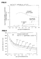
- FIG. 2 and FIG. 3 are views illustrating the relationship between the thickness of a LiNbO 3 film when a piezoelectric substrate in which a LiNbO 3 film with Euler angles (90°, 90°, 0°) is laminated on an R-plane sapphire substrate with Euler angles (0°, 122°23', 0°) is and the acoustic velocity of surface acoustic waves and between the thickness and the electromechanical coupling coefficient k 2 of both structures of FIG. 1 and FIG. 33 , respectively.
- a difference in the electromechanical coupling coefficient k 2 in the structures of FIG. 1 and FIG. 33 is not so large.
- LiNbO 3 is abbreviated as a LN film as appropriate.
- a 0th order surface acoustic wave and primary order, secondary order, and tertiary order surface acoustic waves which are higher order mode surface acoustic waves are excited as illustrated in FIG. 2 .
- FIG. 3 when a primary order surface acoustic wave and a secondary order surface acoustic wave are used, a high electromechanical coupling coefficient can be obtained as compared with the case where a 0th order surface acoustic wave is used.
- FIG. 2 shows that the acoustic velocity of the primary order surface acoustic wave can be considerably increased to about 4600 m/second or more when the thickness of the LN film is below 1.6 ⁇ or lower when (90°, 90°, 0°) LN film / (0°, 122°23', 0°) R-plane sapphire is used.
- the acoustic velocity is as high as 5100 m/second or more when the film thickness of the LN film is 1.6 ⁇ or lower, more specifically in the range of 0.4 ⁇ to 1.6 ⁇ .
- the acoustic velocity of the surface acoustic wave is considerably increased to 5300 m/second or more when the film thickness of the LN film is in the range of 0.6 ⁇ to 1.6 ⁇ .
- FIG. 3 shows that when a primary order surface acoustic wave, a secondary order surface acoustic wave, and a tertiary order surface acoustic wave are used, the electromechanical coupling coefficient k 2 can be increased as compared with the case where a 0th order surface acoustic wave is used, in such a range where the acoustic velocity is high.
- the electromechanical coupling coefficient can be increased as compared with the case of the 0th order surface acoustic wave over the range of the film thickness of the LN film of 0 to 1.6 ⁇ .
- the electromechanical coupling coefficient k 2 can be increased to 0.1 or more. More preferably, by adjusting the film thickness of the LN film in the range of 0.15 ⁇ to 0.9 ⁇ , the electromechanical coupling coefficient k 2 of 0.15 or more can be achieved.
- the electromechanical coupling coefficient k 2 of 0.025 or more can be achieved over the range of the film thickness of the LN film of 0.4 ⁇ to 1.6 ⁇ . More preferably, it is found that, by adjusting the thickness in the range of 0.6 ⁇ to 1.6 ⁇ , the electromechanical coupling coefficient k 2 of 0.03 or more can be achieved.
- the electromechanical coupling coefficient k 2 of 0.03 or more can be achieved by adjusting the film thickness of the LN film to 0.1 ⁇ to 1.6 ⁇ .
- FIG. 3 shows the electromechanical coupling coefficient k 2 of both the structures of the structure of FIG. 1 which is one embodiment of the invention and FIG. 33 which is a modification thereof.
- the structure of FIG. 33 which is a modification is different from the structure of FIG. 1 which is an embodiment in that a short circuit electrode is provided between the sapphire substrate and the LN film.
- those represented as the primary order SAW, the secondary order SAW, and the tertiary order SAW represent the electromechanical coupling coefficients k 2 of the structure of FIG. 1 .
- those represented as the primary order SAW vfm-vmm, the secondary order SAW vfm-vmm, and tertiary order SAW vfm-vmm represent the electromechanical coupling coefficients k 2 of the structure of FIG. 33 .
- the electromechanical coupling coefficient k 2 which is almost the same as that of the embodiment is obtained by adjusting the film thickness of the LN film to be almost the same as the film thickness of the embodiment.
- FIG. 2 and FIG. 3 the Euler angles of the LN film were (90°, 90°, 0°) and the Euler angles of the R-plane sapphire were (0°, 122°23', 0°). The changes in the Euler angles when the propagation direction ⁇ was changed were confirmed.
- FIG. 4 and FIG. 5 are views illustrating the relationship between the thickness of the LN film when the Euler angles of the LN film are (90°, 90°, 5°) and the Euler angles of the R-plane sapphire are (0°, 122°23', 5°) and the acoustic velocity and between the thickness and the electromechanical coupling coefficient k 2 of surface acoustic waves, respectively.
- the vff in FIG. 4 refers to the acoustic velocity of surface acoustic waves in the open state in the piezoelectric substrate of the structure of FIG. 1 .
- the vff in FIG. 6 and FIG. 7 described below refer to the acoustic velocity in the open state in the piezoelectric substrate of the structure of FIG. 1 and the vmf refers to the acoustic velocity in the short circuit state.
- the vfm in FIG. 3 refers to the acoustic velocity of surface acoustic waves in the open state in the piezoelectric substrate of the structure of FIG. 33 .
- the vmm refers to the acoustic velocity in the short circuit state in the piezoelectric substrate of the structure of FIG. 33 .
- the acoustic velocity of the surface acoustic waves decreases as an increase in the thickness of the LN film in all of the cases where the propagation direction ⁇ is 0°, 5°, 10°, 20°, 40°, or 70°.
- the thickness of the LN film is in the range 0.8 ⁇ or lower, the acoustic velocity of the surface acoustic waves can be increased to 4000 m/second in all of the cases.
- the acoustic velocity of the surface acoustic waves can be increased to 4300 m/second or more when ⁇ is lower than 20°, and preferably, by adjusting ⁇ to be 10° or lower, the acoustic velocity of the surface acoustic waves can be increased to 4400 m/second or more.
- FIG. 7 it is found that, by adjusting the propagation direction ⁇ to be lower than 20°, a high electromechanical coupling coefficient k 2 is obtained.
- the propagation direction ⁇ is desirably 15° or lower.
- the electromechanical coupling coefficient k 2 can be increased. More preferably, FIG. 7 shows that, by adjusting the propagation direction ⁇ to 5° or lower, a high electromechanical coupling coefficient k 2 can be obtained.
- the electromechanical coupling coefficient k 2 can be effectively increased by adjusting the film thickness of the LN film in the range of 0.1 ⁇ to 1.6 ⁇ when the Euler angle ⁇ is -5° or more and +5° or lower and by adjusting the film thickness in the range of 0.18 ⁇ to 0.75 ⁇ when ⁇ is -15° or more and lower than -5° or larger than +5° and +15° or lower.
- the Euler angles of the R-plane sapphire may be in the range of (0°, 122°23', 0° ⁇ 15°), in other words in the range of (0°, 122°23', -15° to 15°), and preferably in the range of (0°, 122°23', -5° to 5°).
- FIG. 8 and FIG. 9 are views illustrating the relationship between the thickness of a LiNbO 3 film in the case of the structure of FIG. 1 employing a piezoelectric substrate in which a LiNbO 3 film with Euler angles (0°, 90°, 0°) is formed on an R-plane sapphire substrate with Euler angles (0°, 122°23', 0°) and the acoustic velocity of surface acoustic waves and between the thickness and the electromechanical coupling coefficient k 2 , respectively.
- a 0th order surface acoustic wave, a primary order surface acoustic wave, a secondary order surface acoustic wave, and a tertiary order surface acoustic wave are excited as illustrated in FIG. 8 .
- a high electromechanical coupling coefficient can be obtained as compared with the case where the 0th order surface acoustic wave is used.
- the acoustic velocity of the primary order surface acoustic wave can be considerably increased to about 4400 m/second or more over the range of the thickness of the LN film of 1.6 ⁇ or lower.
- the secondary order surface acoustic wave it is found that when the film thickness of the LN film is in the range of 1.6 ⁇ or lower and more specifically in the range of 0.4 ⁇ to 1.6 ⁇ , the acoustic velocity is as high as 5300 m/second or more. With respect to the tertiary order surface acoustic wave, when the film thickness of the LN film is in the range of 0.65 ⁇ to 0.9 ⁇ , the acoustic velocity of the surface acoustic wave is considerably increased to 4900 m/second or more.
- FIG. 9 shows that when the primary order surface acoustic wave, the secondary order surface acoustic wave, and the tertiary order surface acoustic wave are used, the electromechanical coupling coefficient k 2 can be increased us compared with the case where the 0th order surface acoustic wave is used in such a range where the acoustic velocity is high.
- the electromechanical coupling coefficient can be increased over the range of the film thickness of the LN film of 0 to 1.6 ⁇ as compared with the case of the 0th order surface acoustic wave.
- the electromechanical coupling coefficient k 2 can be increased to 0.1 or more by adjusting the film thickness of the LN film in the range of 0.1 ⁇ to 1.6 ⁇ and, more preferably, the electromechanical coupling coefficient k 2 of 0.15 ⁇ or more can be achieved by adjusting the film thickness of the LN film in the range of 0.14 ⁇ to 1.2 ⁇ .
- the electromechanical coupling coefficient k 2 can be increased to 0.025 or more by adjusting the film thickness of the LN film in the range of 0.4 ⁇ to 1.6 ⁇ and, more preferably, an electromechanical coupling coefficient k 2 of 0.03 or more can be achieved by adjusting the film thickness of the LN film in the range of 0.6 ⁇ to 1.6 ⁇ .
- an electromechanical coupling coefficient k 2 of 0.02 or more can be achieved by adjusting the film thickness of the LN film to 0.6 ⁇ to 1.6 ⁇ .
- FIG. 8 and FIG. 9 are views illustrating the relationship between the thickness of an LN film when the Euler angles of the LN film are (0°, 90°, 5°) and the Euler angles of the R-plane sapphire are (0°, 122°23', 5°) and the acoustic velocity and between the thickness and the electromechanical coupling coefficient k 2 of surface acoustic waves, respectively.
- the acoustic velocity of the surface acoustic waves decreases as the thickness of the LN film increases, in all of the cases where the propagation direction ⁇ is 0°, 5°, 10°, 20°, 40°, or 70°.
- the thickness of the LN film is in the range 0.9 ⁇ or lower, the acoustic velocity of the surface acoustic waves can be increased to 4000 m/second or more in all of the cases.
- the acoustic velocity of the surface acoustic waves can be increased to 4400 m/second or more when ⁇ is lower than 20° and preferably, by adjusting ⁇ to be 10° or lower, the acoustic velocity of the surface acoustic waves can be increased to 4500 m/second or more.
- FIG. 13 it is found that, by adjusting the propagation direction ⁇ to be lower than 20°, a high electromechanical coupling coefficient k 2 is obtained.
- the propagation direction ⁇ is desirably 15° or lower.
- the electromechanical coupling coefficient k 2 can be increased.
- FIG. 7 shows that, by adjusting the propagation direction ⁇ to 10° or lower, a high electromechanical coupling coefficient k 2 can be obtained.
- the Euler angles of the R-plane sapphire may be in the range of (0°, 122°23', 0° ⁇ 15°), in other words in the range of (0°, 122°23', -15° to 15°), and more preferably in the range of (0°, 122°23', -5° to 5°).
- the electromechanical coupling coefficient k 2 can be effectively increased by adjusting the film thickness of the LN film in the range of 0.1 ⁇ to 1.6 ⁇ when the Euler angle ⁇ is -5° or more and +5° or lower and by adjusting the film thickness in the range of 0.18 ⁇ to 0.75 ⁇ when ⁇ is -15° or more and lower than -5°, or larger than +5° and +15° or lower.
- the present inventors have found that when a piezoelectric substrate in which a LN film with Euler angles (90°, 90°, 0°) or (0°, 90°, 0°) is laminated on an R-plane sapphire with Euler angles (0°, 122°39', -15° to 15°) is used, an increase in the acoustic velocity and an increase in the electromechanical coupling coefficient k 2 of surface acoustic waves can be achieved. Furthermore, it is found that when AI is used for the electrodes, the reflection coefficient or the electromechanical coupling coefficient k 2 can be increased by adjusting the thickness of the AI film in a specific range.
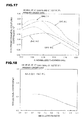
- FIG. 14 and FIG. 15 are a view illustrating the relationship, in a surface acoustic wave device in which an AI film is laminated on a piezoelectric substrate containing LN film with Euler angles (90°, 90°, 0°) / R-plane sapphire with Euler angles (0°, 122°23', 0°), between the thickness of the AI film, the thickness of the LN film, and the reflection coefficient and a view illustrating the relationship between the thickness of the Al film, the thickness of the LN film, and the electromechanical coupling coefficient k 2 , respectively.
- FIG. 14 and FIG. 15 show the results about primary order surface acoustic waves.
- the metallization ratio of the electrodes made of Al was set to 0.5.
- FIG. 14 it is found that the reflection coefficient becomes higher as the thickness of the Al film increases, in all of the cases where the thickness of the LN film is 0.15 ⁇ , 0.2 ⁇ , 0.3 ⁇ , or 0.8 ⁇ .
- FIG. 15 shows that the electromechanical coupling coefficient k 2 can be made as high as 0.08 or more when the thickness of the Al film is 0.02 ⁇ or more and 0.16 ⁇ or lower.
- the thickness of the Al film may be adjusted in the range of 0.02 ⁇ to 0.16 ⁇ . More preferably, it is found that, by adjusting the thickness of the Al film in the range of 0.04 or more and 0.14 or lower, a reflection coefficient of 0.15 or more can be achieved and an electromechanical coupling coefficient k 2 of 0.1 or more can be achieved.
- FIG. 16 and FIG. 17 are a view illustrating the relationship, in a surface acoustic wave device in which an Al film is laminated on a piezoelectric substrate containing LN film with Euler angles (0°, 90°, 0°) / R-plane sapphire with Euler angles (0°, 122°23', 0°), between the thickness of the Al film, the thickness of the LN film, and the reflection coefficient and a view illustrating the relationship between the thickness of the Al film, the thickness of the LN film, and the electromechanical coupling coefficient k 2 , respectively.
- FIG. 16 and FIG. 17 show the results about primary order surface acoustic waves.
- the metallization ratio of the electrodes made of Al was set to 0.5.
- FIG. 16 shows that the reflection coefficient becomes higher as the thickness of the Al film in all of the cases where the thickness of the LN film is 0.14 ⁇ , 0.19 ⁇ , 0.3 ⁇ , or 0.8 ⁇ .
- FIG. 17 shows that the electromechanical coupling coefficient k 2 can be made as high as 0.1 or more when the thickness of the Al film is 0.02 ⁇ or more and 0.16 ⁇ or lower.
- the thickness of the Al film may be adjusted in the range of 0.02 ⁇ to 0.16 ⁇ . More preferably, it is found that, by adjusting the thickness of the Al film in the range of 0.04 ⁇ or more and 0.13 ⁇ or lower, a reflection coefficient of 0.15 or more can be achieved and an electromechanical coupling coefficient k 2 of 0.15 or more can be achieved.
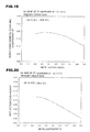
- FIG. 18 and FIG. 19 are views illustrating the relationship, in a surface acoustic wave device in which an Al film is 0.15 ⁇ and electrodes made of a 0.02 ⁇ Al film are formed on a piezoelectric substrate containing LN film with Euler angles (90°, 90°, 0°) / R-plane sapphire with Euler angles (0°, 122°23', 0°), between the metallization ratio of the electrodes and the reflection coefficient and between the metallization ratio and the electromechanical coupling coefficient k 2 , respectively.
- the reflection coefficient tends to decrease as the metallization ratio increases.
- the electromechanical coupling coefficient k 2 can be made as high as 0.16 or more while increasing the reflection coefficient to 0.06 or more. More specifically, it is found that, by adjusting the metallization ratio in the range of 0.2 to 0.7, the reflection coefficient can be increased and further a sufficient electromechanical coupling coefficient k 2 can be achieved. More preferably, the metallization ratio is in the range of 0.2 to 0.65. In such a case, it is found that the reflection coefficient can be further increased to 0.07 or more and the electromechanical coupling coefficient k 2 can be further increased to 0.17 or more.
- FIG. 20 and FIG. 21 are views illustrating the relationship, in a surface acoustic wave device in which a LN film is 0.14 ⁇ and electrodes made of a 0.019 ⁇ Al film are formed on a piezoelectric substrate containing LN film with Euler angles (0°, 90°, 0°) / R-plane sapphire with Euler angles (0°, 122°23', 0°), between the metallization ratio of the electrodes and the reflection coefficient and between the metallization ratio and the electromechanical coupling coefficient k 2 , respectively.
- the reflection coefficient tends to decrease as the metallization ratio increases.
- the electromechanical coupling coefficient k 2 can be made as high as 0.155 or more while increasing the reflection coefficient to 0.06 or more. More specifically, it is found that, by adjusting the metallization ratio in the range of 0.2 to 0.7, the reflection coefficient can be increased and further a sufficient electromechanical coupling coefficient k 2 can be achieved. More preferably, the metallization ratio is in the range of 0.2 to 0.62. In such a case, it is found that the reflection coefficient can be further increased to 0.07 or more and the electromechanical coupling coefficient k 2 can be further increased to 0.17 or more.
- FIG. 22 is a view illustrating the relationship between the thickness of a LN film of a piezoelectric substrate containing LN film with Euler angles (90°, 90°, 0°) /R-plane sapphire with Euler angles (0°, 122°23', 0°) and the temperature coefficient of frequency TCF of a primary order surface acoustic wave.
- FIG. 23 is a view illustrating the relationship between the thickness of a LN film of a piezoelectric substrate containing LN film with Euler angles (0°, 90°, 0°) /R-plane sapphire with Euler angles (0°, 122°23', 0°) and the temperature coefficient of frequency TCF of a surface acoustic wave.
- the present inventors have found that, even when an a-plane sapphire is used in place of the R-plane sapphire, an increase in the acoustic velocity of surface acoustic waves and an increase in the electromechanical coupling coefficient k 2 can be achieved by adjusting the crystal orientation of the LN film in a specific direction.
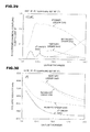
- FIG. 24 and FIG. 25 are views illustrating the relationship, in a piezoelectric substrate containing LN film with Euler angles (0°, 90°, 0°) / a-plane sapphire with Euler angles (0°, 90°, 0°), between the thickness of the LN film and the acoustic velocity of surface acoustic waves or the electromechanical coupling coefficient k 2 , respectively.
- the acoustic velocity of the surface acoustic waves can be increased regardless of the film thickness of the LN film when the film thickness of the LN film is in the range 1.6 ⁇ or lower as compared with the case of a 0th order surface acoustic wave.
- an acoustic velocity of 4500 m/second or more is obtained in the case of the primary order surface acoustic wave
- an acoustic velocity of 4800 m/second or more is obtained in the case of the secondary order surface acoustic wave
- an acoustic velocity of 5100 m/second or more is obtained in the case of the tertiary order surface acoustic wave.
- the electromechanical coupling coefficient k 2 can be increased to 0.1 or more over the range of the film thickness of the LN film of 0.1 ⁇ or more and 1.6 ⁇ or lower when the primary order surface acoustic wave is used.
- the electromechanical coupling coefficient k 2 can be increased to 0.025 or more by adjusting the film thickness of the LN film in the range of 0.5 ⁇ or more and 1.6 ⁇ or lower. It is found that when the tertiary order surface acoustic wave is used, the electromechanical coupling coefficient k 2 can be increased to 0.02 or more by adjusting the film thickness of the LN film in the range of 0.6 ⁇ or more and 1.6 ⁇ or lower.
- FIG. 26 and FIG. 27 are views illustrating the relationship, in a piezoelectric substrate containing LN film with Euler angles (90°, 90°, 0°) / a-plane sapphire with Euler angles (0°, 90°, 0°), between the thickness of the LN film and the acoustic velocity of surface acoustic waves or between the thickness and the electromechanical coupling coefficient k 2 , respectively.
- the acoustic velocity of the acoustic waves can be increased regardless of the film thickness of the LN film when the film thickness of the LN film is in the range 1.6 ⁇ or lower as compared with the case of a 0th order surface acoustic wave.
- an acoustic velocity of 4500 m/second or more is obtained in the case of the primary order surface acoustic wave
- an acoustic velocity of 4800 m/second or more is obtained in the case of the secondary order surface acoustic wave
- an acoustic velocity of 5100 m/second or more is obtained in the case of the tertiary order surface acoustic wave.
- the electromechanical coupling coefficient k 2 can be increased to 0.1 or more over the range of the film thickness of the LN film of 0.1 ⁇ or more and 1.6 ⁇ or lower. It is found that when the secondary order surface acoustic wave is used, the electromechanical coupling coefficient k 2 can be increased to 0.02 or more by adjusting the film thickness of the LN film in the range of 0.05 ⁇ or more and 1.6 ⁇ or lower.
- the electromechanical coupling coefficient k 2 can be increased to 0.02 or more by adjusting the film thickness of the LN film in range of 0.06 ⁇ or more and 1.6 ⁇ or lower
- the present inventors have found that, also in the case where a piezoelectric substrate is used in which a LN film is laminated on an m-plane sapphire, besides the R-plane sapphire or the a-plane sapphire, i.e., a sapphire substrate with Euler angles (90°, 90°, 0°), a high electromechanical coupling coefficient and a high acoustic velocity can be obtained by adjusting the crystal orientation of the LN film in a specific direction.
- FIG. 28 and FIG. 29 are views illustrating the relationship, in a piezoelectric substrate containing LN film with Euler angles (0°, 90°, 0°) / m-plane sapphire with Euler angles (90°, 90°, 0°), between the thickness of the LN film and the acoustic velocity of surface acoustic waves or between the thickness and the electromechanical coupling coefficient k 2 of surface acoustic waves, respectively.
- the acoustic velocity of the surface acoustic waves can be increased regardless of the film thickness of the LN film when the film thickness of the LN film is in the range 1.6 ⁇ or lower as compared with the case of a 0th order surface acoustic wave.
- an acoustic velocity of 4500 m/second or more is obtained in the case of the primary order surface acoustic wave
- an acoustic velocity of 4800 m/second or more is obtained in the case of the secondary order surface acoustic wave
- an acoustic velocity of 5100 m/second or more is obtained in the case of the tertiary order surface acoustic wave.
- the electromechanical coupling coefficient k 2 can be increased to 0.1 or more over the range of the film thickness of the LN film of 0.1 ⁇ or more and 1.6 ⁇ or lower when the primary order surface acoustic wave is used. Moreover, it is found that when the secondary order surface acoustic wave is used, the electromechanical coupling coefficient k 2 can be increased to 0.02 or more by adjusting the film thickness of the LN film in the range of 0.5 ⁇ or more and 1.6 ⁇ or lower.
- the electromechanical coupling coefficient k 2 can be increased to 0.015 or more by adjusting the film thickness of the LN film in the range of 0.06 ⁇ or more and 1.6 ⁇ or lower.
- FIG. 30 and FIG. 31 are views illustrating the relationship, in a piezoelectric substrate containing LN film with Euler angles (90°, 90°, 0°) / m-plane sapphire with Euler angles (90°, 90°, 0°), between the thickness of the LN film and the acoustic velocity of surface acoustic waves or between the thickness and the electromechanical coupling coefficient k 2 , respectively.
- the acoustic velocity of the surface acoustic waves can be increased regardless of the film thickness of the LN film when the film thickness of the LN film is in the range 1.6 ⁇ or lower as compared with the case of a 0th order surface acoustic wave.
- an acoustic velocity of 4500 m/second or more is obtained in the case of the primary order surface acoustic wave
- an acoustic velocity of 4800 m/second or more is obtained in the case of the secondary order surface acoustic wave
- an acoustic velocity of 5100 m/second or more is obtained in the case of the tertiary order surface acoustic wave.
- the electromechanical coupling coefficient k 2 can be increased to 0.1 or more over the range of the film thickness of the LN film of 0.1 ⁇ or more and 1.6 ⁇ or lower when the primary order surface acoustic wave is used. Moreover, it is found that when the secondary order surface acoustic wave is used, the electromechanical coupling coefficient k 2 can be increased to 0.04 or more by adjusting the film thickness of the LN film in the range of 0.5 ⁇ or more and 1.6 ⁇ or lower.
- the electromechanical coupling coefficient k 2 can be increased to 0.03 or more by adjusting the film thickness of the LN film in the range of 0.06 ⁇ or more and 1.6 ⁇ or lower.
Landscapes
- Physics & Mathematics (AREA)
- Acoustics & Sound (AREA)
- Chemical & Material Sciences (AREA)
- Engineering & Computer Science (AREA)
- Materials Engineering (AREA)
- Surface Acoustic Wave Elements And Circuit Networks Thereof (AREA)
Abstract
Description
- The present invention relates to a surface acoustic wave device for use in a resonator a band-pass filter, and the like and more specifically relates to a surface acoustic wave device employing a piezoelectric substrate in which an epitaxial LiNbO3 film is laminated on a sapphire substrate.
- In recent years, an increase in frequency has been required also in surface acoustic wave devices with an increase in frequency in communication apparatuses and the like. Moreover, in a surface acoustic wave filter and the like, an increase in band has also been strongly required.
- In order to achieve an increase in frequency and an increase in band, it has been required that the acoustic velocity and the electromechanical coupling coefficient k2 of surface acoustic waves are high.
- In order to satisfy the above-described requirements,
Patent Literature 1 discloses a surfaceacoustic wave device 1001 illustrated inFig. 32 . - The surface
acoustic wave device 1001 employs apiezoelectric substrate 1004 in which a (100) LiNbO3film 1003 is laminated on a (012)sapphire substrate 1002. On thepiezoelectric substrate 1004,input electrodes 1005 andoutput electrodes 1006 are provided. The projector direction of the c axis on thesapphire substrate 1002 and the c axis direction of the LiNbO3film 1003 are parallel to each other. Therefore, it is disclosed that the acoustic velocity and the electromechanical coupling coefficient k2 of surface acoustic waves can be increased by controlling the propagation direction of the surface acoustic waves. - In contrast,
Patent Literature 2 discloses a surface acoustic wave device employing a piezoelectric substrate in which a (012) LiNbO3 film is laminated on a (012) sapphire substrate or a piezoelectric substrate in which a (100) LiNbO3 film is laminated on a (012) sapphire substrate. -
- Patent Literature 1: Japanese Unexamined Patent Application Publication No.
10-322158 - Patent Literature 2: International Publication No.
WO98/56109 - According to the surface acoustic wave device disclosed in
Patent Literature 1 orPatent Literature 2, an increase in the velocity or an electromechanical coupling coefficient of surface acoustic waves has been achieved by the use of the piezoelectric substrate in which the (100) LiNbO3 film or the (012) LiNbO3 film is laminated on the (012) sapphire substrate, i.e., R-plane sapphire substrate. However, in recent years, a further increase in frequency or a further increase in band has been required, and thus an increase in the acoustic velocity and the electromechanical coupling coefficient k2 of surface acoustic waves has been more strongly demanded. - Moreover, in order to achieve a reduction in the size of surface acoustic wave devices, an increase in a reflection coefficient has also been strongly demanded.
- It is an object of the invention to provide a surface acoustic wave device in which the acoustic velocity and the electromechanical coupling coefficient k2 of surface acoustic waves can be further increased and moreover a reflection coefficient can be increased as compared with conventional surface acoustic wave devices in view of the present circumstances of the former techniques described above.
- The present inventors have constantly examined in order to achieve an increase in the velocity of surface acoustic waves in a surface acoustic wave device. As a result, the present inventors have found that when a sapphire substrate of a specific crystal orientation and a LiNbO3 film of a specific crystal orientation are combined in a configuration employing a piezoelectric substrate in which a LiNbO3 film is laminated on an R-plane, a-plane, or m-plane sapphire substrate, the acoustic velocity of surface acoustic waves is effectively increased, and thus have accomplished the present invention.
- More specifically, a person skilled in the art cannot imagine increasing the acoustic velocity of surface acoustic waves by the use of the above-described specific sapphire substrate and the above-described specific LiNbO3 film when the present application was filed, and the acoustic velocity of surface acoustic waves cannot be effectively increased without using the specific combination of the invention.
- According to a wide aspect of the invention, a surface acoustic wave device is provided which has: a piezoelectric substrate having an R-plane, a-plane, or m-plane sapphire substrate and a LiNbO3 film of (90°, 90°, -15° to 15°) in terms of Euler angles (φ, θ, Ψ) formed on the sapphire substrate; and electrodes formed on the piezoelectric substrate and made of metal.
- In a specific aspect of the surface acoustic wave device according to the invention, a primary order mode of a surface acoustic wave is utilized, and when the wavelength of the surface acoustic wave is defined as λ, the LiNbO3 film thickness is in the range of 0.1 λ to 1.6 λ and preferably in the range of 0.15 λ to 0.9 λ when the Euler angle Ψ is -5° or more and +5° or lower, i.e., in the range of 0° ± 5° and is in the range of 0.18 λ to 0.75 λ when Ψ is -15° or more and lower than -5° or larger than +5° and +15° or lower. Thus, the acoustic velocity of the surface acoustic waves can be further increased and the electromechanical coupling coefficient k2 can be further increased.
- In another specific aspect of the surface acoustic wave device according to the invention, a secondary order mode of a surface acoustic wave is utilized, and when the wavelength of the surface acoustic wave is defined as λ, the LiNbO3 film thickness is in the range of 0.4 λ to 1.6 λ and preferably in the range of 0.6 λ to 1.6 λ when the Euler angle Ψ is -5° to 5°.
- In another specific aspect of the surface acoustic wave device according to the invention, a tertiary order mode of a surface acoustic wave is utilized, and when the wavelength of the surface acoustic wave is defined as λ, the LiNbO3 film thickness is in the range of 0.6 λ to 1.6 λ when the Euler angle Ψ is -5° to 5°. In this case, by utilizing the tertiary order mode, a further increase in frequency can be achieved and a further increase in the acoustic velocity and the electromechanical coupling coefficient k2 of the surface acoustic waves can be achieved.
- In another specific aspect of the surface acoustic wave device according to the invention, the electrodes are made of Al, and when the wavelength of the surface acoustic waves is defined as λ, the thickness of the electrodes made of Al is in the range of 0.02 λ to 0.16 λ. In this case, the electromechanical coupling coefficient k2 can be further increased and the reflection coefficient can be increased.
- In another specific aspect of the surface acoustic wave device according to the invention, the metallization ratio of the electrodes is in the range of 0.2 to 0.7. Thus, the reflection coefficient can be further increased and the electromechanical coupling coefficient k2 can be increased.
- In another wide aspect of the invention, a surface acoustic wave device is provided which has: a piezoelectric substrate having an R-plane, a-plane, or m-plane sapphire substrate and a LiNbO3 film of (0°, 90°, -15° to 15°) in terms of Euler angles (φ, θ, Ψ) formed on the sapphire substrate; and electrodes formed on the piezoelectric substrate and made of metal.
- In a specific aspect of the surface acoustic wave device, a primary order mode of a surface acoustic wave is utilized, and when the wavelength of surface acoustic wave is defined as λ, the LiNbO3 film thickness is in the range of 0.1 λ to 1.6 λ and preferably in the range of 0.12 λ to 1.2 λ when the Euler angle Ψ is -5° or more and +5° or lower and is in the range of 0.17 λ to 0.8 λ when Ψ is -15° or more and lower than -5° or larger than +5° and +15° or lower. In this case, the acoustic velocity and the electromechanical coupling coefficient k2 of the surface acoustic waves can be further increased.
- In another specific aspect of the surface acoustic wave device according to the invention, a secondary order mode of a surface acoustic wave is utilized, and when the wavelength of the surface acoustic wave is defined as λ, the LiNbO3 film thickness is in the range of 0.4 λ to 1.6 λ when the Euler angle Ψ is -5° to 5°.
- In another specific aspect of the surface acoustic wave device according to the invention, a tertiary order mode of a surface acoustic wave is utilized, and when the wavelength of the surface acoustic wave is defined as λ, the LiNbO3 film thickness is in the range of 0.6 λ to 1.0 λ when the Euler angle Ψ is -5° to 5°.
- In another specific aspect of the surface acoustic wave device according to the invention, the electrodes are made of Al, and when the wavelength of the surface acoustic waves is defined as λ, the thickness of the electrodes made of Al is in the range of 0.02 λ to 0.16 λ and preferably in the range of 0.04 λ to 0.14 λ. In this case, the reflection coefficient can be increased and the electromechanical coupling coefficient k2 can be further increased.
- In another specific aspect of the surface acoustic wave device provided in the second aspect of the invention, the metallization ratio of the electrodes is in the range of 0.2 to 0.7. In this case, the reflection coefficient can be increased and the electromechanical coupling coefficient k2 can be further increased.
- In another specific aspect of the surface acoustic wave device according to the invention, a primary order mode of a surface acoustic wave is utilized, and the piezoelectric substrate further has a short circuit electrode between the R-plane, a-plane, or m-plane sapphire substrate and the LiNbO3 film. Thus, the acoustic velocity can be further increased.
- In another specific aspect of the surface acoustic wave device according to the invention, when the wavelength of the surface acoustic wave is defined as λ, the LiNbO3 film thickness is in the range of 0.15 λ to 1.6 λ and preferably in the range of 0.2 λ to 0.75 λ. Thus, the acoustic velocity can be further increased.
- In another specific aspect of the surface acoustic wave device according to the invention, a secondary order mode of surface acoustic wave is utilized, and the piezoelectric substrate further has a short circuit electrode between the R-plane, a-plane, or m-plane sapphire substrate and the LiNbO3 film. Thus, the acoustic velocity can be further increased.
- In another specific aspect of the surface acoustic wave device according to the invention, when the wavelength of the surface acoustic wave is defined as λ, the LiNbO3 film thickness is in the range of 0.4 λ to 1.6 λ and preferably in the range of 0.6 λ to 1.6 λ. Thus, the acoustic velocity can be further increased. Advantageous Effects of Invention
- According to the surface acoustic wave device provided in the first wide aspect, since the piezoelectric substrate in which the LiNbO3 with Euler angles (90°, 90°, -15° to 15°) is formed on the R-plane, a-plane, or m-plane sapphire substrate is employed, the acoustic velocity of the used surface acoustic waves can be increased and the electromechanical coupling coefficient k2 can be sufficiently increased. Therefore, an increase in frequency and an increase in band of the surface acoustic wave device can be achieved.
- According to the surface acoustic wave device provided in the second large aspect, since the piezoelectric substrate in which the LiNbO3 with Euler angles (0°, 90°, -15° to 15°) is formed on the R-plane, a-plane, or m-plane sapphire substrate is employed, the acoustic velocity of the used surface acoustic waves can be increased and the electromechanical coupling coefficient k2 can be sufficiently increased. Therefore, an increase in frequency and an increase in band of the surface acoustic wave device can be achieved.
- In the following description, LiNbO3 is abbreviated as LN depending on cases. Brief Description of Drawings
-
- [
FIG. 1] FIG. 1 is a front cross sectional view of a surface acoustic wave device according to one embodiment of the invention. - [
FIG. 2] FIG. 2 is a view illustrating the relationship between the thickness of a LN film in a piezoelectric substrate containing (90°, 90°, 0°) LN film / (0°, 122°23', 0°) R-plane sapphire and the acoustic velocity of surface acoustic waves. - [
FIG. 3] FIG. 3 is a view illustrating the relationship between the thickness of a LN film in a piezoelectric substrate containing (90°, 90°, 0°) LN film/ (0°, 122°23', 0°) R-plane sapphire and a piezoelectric substrate containing (90°, 90°, 0°) LN film / Short circuit electrode / (0°, 122°23', 0°) R-plane sapphire (both structures ofFIG. 1 andFIG. 33 ) and the electromechanical coupling coefficient k2. - [
FIG. 4] FIG. 4 is a view illustrating the relationship between the thickness of a LN film in a piezoelectric substrate containing (90°, 90°, 5°) LN film / (0°, 122°23', 5°) R-plane sapphire and the acoustic velocity of surface acoustic waves. - [
FIG. 5] FIG. 5 is a view illustrating the relationship between the thickness of a LN film in a piezoelectric substrate containing LN (90°, 90°, 5°) film / (0°, 122°23', 5°) R-plane sapphire (structure ofFIG. 1 ) and the electromechanical coupling coefficient k2. - [
FIG. 6] FIG. 6 is a view illustrating the relationship between the thickness of a LN film in a piezoelectric substrate containing (90°, 90°, Ψ) LN film / (0°, 122°23', Ψ) R-plane sapphire, the propagation direction Ψ, and the acoustic velocity of primary order surface acoustic waves. - [
FIG. 7] FIG. 7 is a view illustrating the relationship between the thickness of a LN film in a piezoelectric substrate containing (90°, 90°, Ψ) LN film / (0°, 122°23', Ψ) R-plane sapphire, the propagation direction Ψ, and the electromechanical coupling coefficient k2 of primary order surface acoustic waves. - [
FIG. 8] FIG. 8 is a view illustrating the relationship between the thickness of a LN film in a piezoelectric substrate containing (0°, 90°, 0°) LN film / (0°, 122°23', 0°) R-plane sapphire and the acoustic velocity of surface acoustic waves. - [
FIG. 9] FIG. 9 is a view illustrating the relationship between the thickness of a LN film in a piezoelectric substrate containing LN (0°, 90°, 0°) film / (0°, 122°23', 0°) R-plane sapphire and an electromechanical coupling coefficient k2. - [
FIG. 10] FIG. 10 is a view illustrating the relationship between the thickness of a LN film in a piezoelectric substrate containing (0°, 90°, 5°) LN film / (0°, 122°23', 5°) R-plane sapphire and the acoustic velocity of surface acoustic waves. - [
FIG. 11] FIG. 11 is a view illustrating the relationship between the thickness of a LN film in a piezoelectric substrate containing (0°, 90°, 5°) LN film / (0°, 122°23', 5°) R-plane sapphire and an electromechanical coupling coefficient k2. - [
FIG. 12] FIG. 12 is a view illustrating the relationship between the thickness of a LN film in a piezoelectric substrate containing (0°, 90°, Ψ) LN film / (0°, 122°23', Ψ) R-plane sapphire, the propagation direction Ψ, and the acoustic velocity of primary order surface acoustic waves. - [
FIG. 13] FIG. 13 is a view illustrating the relationship between the thickness of a LN film in a piezoelectric substrate containing (0°, 90°, Ψ) LN film / (0°, 122°23', Ψ) R-plane sapphire, the propagation direction Ψ, and the electromechanical coupling coefficient k2 of primary order surface acoustic waves. - [
FIG. 14] FIG. 14 is a view illustrating the relationship, in a primary order surface acoustic wave device in which AI film interdigital electrodes are laminated on a piezoelectric substrate containing (90°, 90°, 0°) LN film / (0°, 122°23', 0°) R-plane sapphire, between the thickness of the LN film, the thickness of the Al film interdigital electrodes, and the reflection coefficient. - [
FIG. 15] FIG. 15 is a view illustrating the relationship, in a primary order surface acoustic wave device in which AI film interdigital electrodes are laminated on a piezoelectric substrate containing (90°, 90°, 0°) LN film / (0°, 122°23', 0°) R-plane sapphire, between the thickness of the LN film, the thickness of the AI film interdigital electrodes, and the electromechanical coupling coefficient k2. - [
FIG. 16] FIG. 16 is a view illustrating the relationship, in a primary order surface acoustic wave device in which AI film interdigital electrodes are laminated on a piezoelectric substrate containing (0°, 90°, 0°) LN film / (0°, 122°23', 0°) R-plane sapphire, between the thickness of the LN film, the thickness of the AI film interdigital electrodes, and the reflection coefficient. - [
FIG. 17] FIG. 17 is a view illustrating the relationship, in a primary order surface acoustic wave device in which AI film interdigital electrodes are laminated on a piezoelectric substrate containing (0°, 90°, 0°) LN film / (0°, 122°23', 0°) R-plane sapphire, between the thickness of the LN film, the thickness of the AI film interdigital electrodes, and the electromechanical coupling coefficient k2. - [
FIG. 18] FIG. 18 is a view illustrating the relationship, in a surface acoustic wave device in which the thickness of a LN film is 0.15 λ in a piezoelectric substrate containing (90°, 90°, 0°) LN film / (0°, 122º23', 0°) R-plane sapphire and the thickness of AI film interdigital electrodes formed on the piezoelectric substrate is 0.02 λ, between the metallization ratio of the electrodes and the reflection coefficient. - [
FIG. 19] FIG. 19 is a view illustrating the relationship, in a surface acoustic wave device in which the thickness of a LN film is 0.15 λ in a piezoelectric substrate containing (90°, 90°, 0°) LN film / (0°, 122°23', 0°) R-plane sapphire and the thickness of Al film interdigital electrodes formed on the piezoelectric substrate is 0.02 λ, between the metallization ratio of the electrodes and the electromechanical coupling coefficient k2. - [
FIG. 20] FIG. 20 is a view illustrating the relationship, in a surface acoustic wave device in which the thickness of a LN film is 0.14 λ in a piezoelectric substrate containing (0°, 90°, 0°) LN film / (0°, 122°23', 0°) R-plane sapphire and the thickness of Al film interdigital electrodes formed on the piezoelectric substrate is 0.019 λ, between the metallization ratio of the electrodes and the reflection coefficient. - [
FIG. 21] FIG. 21 is a view illustrating the relationship, in a surface acoustic wave device in which the thickness of a LN film is 0.14 λ in a piezoelectric substrate containing (0°, 90°, 0°) LN film / (0°, 122°23', 0°) R-plane sapphire and the thickness of AI film interdigital electrodes formed on the piezoelectric substrate is 0.019 λ, between the metallization ratio of the electrodes and the electromechanical coupling coefficient k2. - [
FIG. 22] FIG. 22 is a view illustrating the relationship between the thickness of a LN film and the temperature coefficient of frequency TCF in a piezoelectric substrate containing (90°, 90°, 0°) LN film / (0°, 122°23', 0°) R-plane sapphire. - [
FIG. 23] FIG. 23 is a view illustrating the relationship between the thickness of a LN film and the temperature coefficient of frequency TCF in a piezoelectric substrate containing (0°, 90°, 0°) LN film / (0°, 122°23', 0°) R-plane sapphire. - [
FIG. 24] FIG. 24 is a view illustrating the relationship between the thickness of a LN film in a piezoelectric substrate containing (0°, 90°, 0°) LN film / (0°, 90°, 0°) a-plane sapphire and the acoustic velocity of surface acoustic waves. - [
FIG. 25] FIG. 25 is a view illustrating the relationship between the thickness of a LN film in a piezoelectric substrate containing (0°, 90°, 0°) LN film / (0°, 90°, 0°) a-plane sapphire and the electromechanical coupling coefficient k2 of surface acoustic waves. - [
FIG. 26] FIG. 26 is a view illustrating the relationship between the thickness of a LN film in a piezoelectric substrate containing (90°, 90°, 0°) LN film / (0°, 90°, 0°) a-plane sapphire and the acoustic velocity of surface acoustic waves. - [
FIG. 27] FIG. 27 is a view illustrating the relationship between the thickness of a LN film in a piezoelectric substrate containing (90°, 90°, 0°) LN film / (0°, 90°, 0°) a-plane sapphire and the electromechanical coupling coefficient k2 of surface acoustic waves. - [
FIG. 28] FIG. 28 is a view illustrating the relationship between the thickness of a LN film in a piezoelectric substrate containing (0°, 90°, 0°) LN film / (90°, 90°, 0°) m-plane sapphire and the acoustic velocity of surface acoustic waves. - [
FIG. 29] FIG. 29 is a view illustrating the relationship between the thickness of a LN film in a piezoelectric substrate containing (0°, 90°, 0°) LN film / (90°, 90°, 0°) m-plane sapphire and the electromechanical coupling coefficient k2 of surface acoustic waves. - [
FIG. 30] FIG. 30 is a view illustrating the relationship between the thickness of a LN film in a piezoelectric substrate containing (90°, 90°, 0°) LN film / (90°, 90°, 0°) m-plane sapphire and the acoustic velocity of surface acoustic waves. - [
FIG. 31] FIG. 31 is a view illustrating the relationship between the thickness of a LN film in a piezoelectric substrate containing (90°, 90°, 0°) LN film / (90°, 90°, 0°) m-plane sapphire and the electromechanical coupling coefficient k2 of surface acoustic waves. - [
FIG. 32] FIG. 32 is a perspective view illustrating a former surface acoustic wave device. - [
FIG. 33] FIG. 33 is a front cross sectional view of interdigital electrodes /LN film / short circuit electrode / sapphire structure. - Hereinafter the details of the invention are described.
-
FIG. 1 is a front cross sectional view of a surface acoustic wave device according to one embodiment of the invention. A surfaceacoustic wave device 1 has apiezoelectric substrate 2. Thepiezoelectric substrate 2 has an R-plane, a-plane, or m-plane sapphire substrate 2a and a LiNbO3 film 2b laminated on the R-plane, a-plane, or m-plane sapphire substrate 2a. When the LibO3 film 2b is represented by the Euler angles (φ, θ, Ψ, the LiNbO3 film 2b is a LiNbO3 film (90°, 90°, -15° to 15°), or (0°, 90°. -15° to 15°). - On the LiNbO3 film 2b,
electrodes 3 made of metal are formed. Theelectrodes 3 have at least one interdigital electrode for exciting surface acoustic waves. The structure of theelectrodes 3 is not particularly limited and an appropriate electrode structure is provided in accordance with the function of surface acoustic wave devices, such as a surface acoustic wave resonator or a surface acoustic wave filter. - Moreover, an appropriate metal can be used for the material of the
electrodes 3, and AI is preferably used. As described later, by adjusting the thickness or the metallization ratio of electrodes made of AI in a specific range, an increase in the acoustic velocity and/or an increase in the reflection coefficient of waves can be achieved. - the configuration and the effects of the above-described surface
acoustic wave 1 are clarified based on specific experimental examples. - In the following description, the crystal orientations of the sapphire substrate and the LiNbO3 are expressed by the Euler angles. The R-plane, sapphire is (0°, 122°23', Ψ) sapphire in terms of the Euler angles, the m-plane sapphire is (90°, 90°, Ψ) in terms of the Euler angles, and the a-plane sapphire is (0°, 90°, Ψ) in terms of the Euler angles.
- In order to express the crystal orientation of the sapphire substrate or the LiNbO3, the Miller index is usually used in addition to the Euler angles. The relationship between the Euler angles and the Miller index is as follows.
- R-plane sapphire: Euler angles (0°, 122°23', 0°) = Miller index (012) is established, and is sometimes expressed as (01-12) by the Miller index.
- Moreover, there are relationships of Euler angles (90°, 90°, 0°) = Miller index (100) and Euler angles (0°, 90°, 0°) = Miller index (010).
-
FIG. 33 is a front cross sectional view illustrating the structure of a modification in which a short circuit electrode 4 is inserted between thesapphire substrate 2a and the LiNbO3 film 2b of the structure ofFIG. 1 . Herein, the electrode material is AI but metals other than AI may be acceptable insofar as the materials can cause an electrical short circuit. -
FIG. 2 andFIG. 3 are views illustrating the relationship between the thickness of a LiNbO3 film when a piezoelectric substrate in which a LiNbO3 film with Euler angles (90°, 90°, 0°) is laminated on an R-plane sapphire substrate with Euler angles (0°, 122°23', 0°) is and the acoustic velocity of surface acoustic waves and between the thickness and the electromechanical coupling coefficient k2 of both structures ofFIG. 1 andFIG. 33 , respectively. A difference in the electromechanical coupling coefficient k2 in the structures ofFIG. 1 andFIG. 33 is not so large. - In the following description, LiNbO3 is abbreviated as a LN film as appropriate.
- In the structure in which the electrodes are formed on the piezoelectric substrate, a 0th order surface acoustic wave and primary order, secondary order, and tertiary order surface acoustic waves which are higher order mode surface acoustic waves are excited as illustrated in
FIG. 2 . As is clear fromFIG. 3 , when a primary order surface acoustic wave and a secondary order surface acoustic wave are used, a high electromechanical coupling coefficient can be obtained as compared with the case where a 0th order surface acoustic wave is used. - Usually, in a surface acoustic wave device employing a LiNbO3 substrate, the acoustic velocity is about 4000 m/second. In contrast,
FIG. 2 shows that the acoustic velocity of the primary order surface acoustic wave can be considerably increased to about 4600 m/second or more when the thickness of the LN film is below 1.6 λ or lower when (90°, 90°, 0°) LN film / (0°, 122°23', 0°) R-plane sapphire is used. Similarly, also about the secondary order surface acoustic wave, it is found that the acoustic velocity is as high as 5100 m/second or more when the film thickness of the LN film is 1.6 λ or lower, more specifically in the range of 0.4 λ to 1.6 λ. Furthermore, about the tertiary order surface acoustic wave, the acoustic velocity of the surface acoustic wave is considerably increased to 5300 m/second or more when the film thickness of the LN film is in the range of 0.6 λ to 1.6 λ. - Moreover,
FIG. 3 shows that when a primary order surface acoustic wave, a secondary order surface acoustic wave, and a tertiary order surface acoustic wave are used, the electromechanical coupling coefficient k2 can be increased as compared with the case where a 0th order surface acoustic wave is used, in such a range where the acoustic velocity is high. - Particularly in the case of the primary order surface acoustic wave, it is found that the electromechanical coupling coefficient can be increased as compared with the case of the 0th order surface acoustic wave over the range of the film thickness of the LN film of 0 to 1.6 λ. Preferably, as is understood from
FIG. 3 , by adjusting the film thickness of the LN film in the range of 0.1 λ to 1.6 λ, the electromechanical coupling coefficient k2 can be increased to 0.1 or more. More preferably, by adjusting the film thickness of the LN film in the range of 0.15 λ to 0.9 λ, the electromechanical coupling coefficient k2 of 0.15 or more can be achieved. - When the secondary order surface acoustic wave is used, the electromechanical coupling coefficient k2 of 0.025 or more can be achieved over the range of the film thickness of the LN film of 0.4 λ to 1.6 λ. More preferably, it is found that, by adjusting the thickness in the range of 0.6 λ to 1.6 λ, the electromechanical coupling coefficient k2 of 0.03 or more can be achieved.
- It is also found that when the tertiary order surface acoustic wave is used, the electromechanical coupling coefficient k2 of 0.03 or more can be achieved by adjusting the film thickness of the LN film to 0.1 λ to 1.6 λ.
-
FIG. 3 shows the electromechanical coupling coefficient k2 of both the structures of the structure ofFIG. 1 which is one embodiment of the invention andFIG. 33 which is a modification thereof. The structure ofFIG. 33 which is a modification is different from the structure ofFIG. 1 which is an embodiment in that a short circuit electrode is provided between the sapphire substrate and the LN film. - In
FIG. 3 , those represented as the primary order SAW, the secondary order SAW, and the tertiary order SAW represent the electromechanical coupling coefficients k2 of the structure ofFIG. 1 . Those represented as the primary order SAW vfm-vmm, the secondary order SAW vfm-vmm, and tertiary order SAW vfm-vmm represent the electromechanical coupling coefficients k2 of the structure ofFIG. 33 . - As is clear from
FIG. 3 , it is found that, also in the primary order, the secondary order, and the tertiary order surface acoustic waves of the structure of the modification, the electromechanical coupling coefficient k2 which is almost the same as that of the embodiment is obtained by adjusting the film thickness of the LN film to be almost the same as the film thickness of the embodiment. - In
FIG. 2 andFIG. 3 , the Euler angles of the LN film were (90°, 90°, 0°) and the Euler angles of the R-plane sapphire were (0°, 122°23', 0°). The changes in the Euler angles when the propagation direction Ψ was changed were confirmed.FIG. 4 andFIG. 5 are views illustrating the relationship between the thickness of the LN film when the Euler angles of the LN film are (90°, 90°, 5°) and the Euler angles of the R-plane sapphire are (0°, 122°23', 5°) and the acoustic velocity and between the thickness and the electromechanical coupling coefficient k2 of surface acoustic waves, respectively. - The vff in
FIG. 4 refers to the acoustic velocity of surface acoustic waves in the open state in the piezoelectric substrate of the structure ofFIG. 1 . Similarly, the vff inFIG. 6 andFIG. 7 described below refer to the acoustic velocity in the open state in the piezoelectric substrate of the structure ofFIG. 1 and the vmf refers to the acoustic velocity in the short circuit state. - Moreover, the vfm in
FIG. 3 refers to the acoustic velocity of surface acoustic waves in the open state in the piezoelectric substrate of the structure ofFIG. 33 . The vmm refers to the acoustic velocity in the short circuit state in the piezoelectric substrate of the structure ofFIG. 33 . - As is clear from
FIG. 4 andFIG. 5 , it is found that, also when the propagation direction Ψ of the Euler angles of the LN film and the R-plane sapphire is changed to 5º from 0°, there is the same tendency as those ofFIG. 2 andFIG. 3 . Similarly as inFIG. 4 andFIG. 5 , the relationship between the thickness of the LN film and the acoustic velocity of surface acoustic waves and the relationship between the thickness and the electromechanical coupling coefficient k2 of surface acoustic waves were determined by changing the propagation direction Ψ of the LN film and the propagation direction Ψ of the R-plane sapphire to 0°, 5°, 10°, 20°, 40°, or 70°. The results are shown inFIG. 6 andFIG. 7 . As illustrated inFIG. 7 , Ψ = 15° is at the midpoint between 10° and 20°. - As is clear from
FIG. 6 , the acoustic velocity of the surface acoustic waves decreases as an increase in the thickness of the LN film in all of the cases where the propagation direction Ψ is 0°, 5°, 10°, 20°, 40°, or 70°. However, it is found that when the thickness of the LN film is in the range 0.8 λ or lower, the acoustic velocity of the surface acoustic waves can be increased to 4000 m/second in all of the cases. - In particular, it is found that when the thickness of the LN film is in the rage of 0.8 λ or lower, the acoustic velocity of the surface acoustic waves can be increased to 4300 m/second or more when Ψ is lower than 20°, and preferably, by adjusting Ψ to be 10° or lower, the acoustic velocity of the surface acoustic waves can be increased to 4400 m/second or more.
- As is clear from
FIG. 7 , it is found that, by adjusting the propagation direction Ψ to be lower than 20°, a high electromechanical coupling coefficient k2 is obtained. Preferably, the propagation direction Ψ is desirably 15° or lower. Thus, the electromechanical coupling coefficient k2 can be increased. More preferably,FIG. 7 shows that, by adjusting the propagation direction Ψ to 5° or lower, a high electromechanical coupling coefficient k2 can be obtained. - Therefore, as is clear from
FIG. 4 to FIG. 7 , it is found that, in the lamination structure of the LiNbO3 with Euler angles (90°, 90°, Ψ) and the sapphire with Euler angles (0°, 122°23', Ψ), when the propagation direction Ψ is lower than 20°, preferably in the range of 15° or lower, and more preferably in the range of 5° or lower, the acoustic velocity of the surface acoustic waves can be increased and the electromechanical coupling coefficient k2 can be effectively increased. - More specifically, the electromechanical coupling coefficient k2 can be effectively increased by adjusting the film thickness of the LN film in the range of 0.1 λ to 1.6 λ when the Euler angle Ψ is -5° or more and +5° or lower and by adjusting the film thickness in the range of 0.18 λ to 0.75 λ when Ψ is -15° or more and lower than -5° or larger than +5° and +15° or lower.
- Even when the propagation direction Ψ is a negative value, the same results when the direction Ψ is a positive value are obtained. Therefore, it is found that the Euler angles of the R-plane sapphire may be in the range of (0°, 122°23', 0° ± 15°), in other words in the range of (0°, 122°23', -15° to 15°), and preferably in the range of (0°, 122°23', -5° to 5°).
-
FIG. 8 andFIG. 9 are views illustrating the relationship between the thickness of a LiNbO3 film in the case of the structure ofFIG. 1 employing a piezoelectric substrate in which a LiNbO3 film with Euler angles (0°, 90°, 0°) is formed on an R-plane sapphire substrate with Euler angles (0°, 122°23', 0°) and the acoustic velocity of surface acoustic waves and between the thickness and the electromechanical coupling coefficient k2, respectively. - In the structure in which electrodes are formed on the piezoelectric substrate, a 0th order surface acoustic wave, a primary order surface acoustic wave, a secondary order surface acoustic wave, and a tertiary order surface acoustic wave are excited as illustrated in
FIG. 8 . As is clear from the drawings, when the primary order surface acoustic wave, the secondary order surface acoustic wave, and the tertiary order surface acoustic wave are used, a high electromechanical coupling coefficient can be obtained as compared with the case where the 0th order surface acoustic wave is used. - Usually, in a surface acoustic wave device employing a LiNbO3 substrate, the acoustic velocity is about 4000 m/second. In contrast, it is found that, in the case where (0°, 90°, 0°) LN film / (0°, 122°23', 0°) R-plane sapphire is used, the acoustic velocity of the primary order surface acoustic wave can be considerably increased to about 4400 m/second or more over the range of the thickness of the LN film of 1.6 λ or lower. Similarly, also about the secondary order surface acoustic wave, it is found that when the film thickness of the LN film is in the range of 1.6 λ or lower and more specifically in the range of 0.4 λ to 1.6 λ, the acoustic velocity is as high as 5300 m/second or more. With respect to the tertiary order surface acoustic wave, when the film thickness of the LN film is in the range of 0.65 λ to 0.9 λ, the acoustic velocity of the surface acoustic wave is considerably increased to 4900 m/second or more.
-
FIG. 9 shows that when the primary order surface acoustic wave, the secondary order surface acoustic wave, and the tertiary order surface acoustic wave are used, the electromechanical coupling coefficient k2 can be increased us compared with the case where the 0th order surface acoustic wave is used in such a range where the acoustic velocity is high. Particularly in the case of the primary order surface acoustic wave, it is found that the electromechanical coupling coefficient can be increased over the range of the film thickness of the LN film of 0 to 1.6 λ as compared with the case of the 0th order surface acoustic wave. As is understood fromFIG. 9 , preferably, the electromechanical coupling coefficient k2 can be increased to 0.1 or more by adjusting the film thickness of the LN film in the range of 0.1 λ to 1.6 λ and, more preferably, the electromechanical coupling coefficient k2 of 0.15 λ or more can be achieved by adjusting the film thickness of the LN film in the range of 0.14 λ to 1.2 λ. - When the secondary order surface acoustic wave is used, the electromechanical coupling coefficient k2 can be increased to 0.025 or more by adjusting the film thickness of the LN film in the range of 0.4 λ to 1.6 λ and, more preferably, an electromechanical coupling coefficient k2 of 0.03 or more can be achieved by adjusting the film thickness of the LN film in the range of 0.6 λ to 1.6 λ.
- It is found that when the tertiary order surface acoustic wave is used, an electromechanical coupling coefficient k2 of 0.02 or more can be achieved by adjusting the film thickness of the LN film to 0.6 λ to 1.6 λ.
- In
FIG. 8 andFIG. 9 , the Euler angles of the LN film were (0°, 90°, 0°) and the Euler angles of the R-plane sapphire were (0°, 122°23', 0°). Here, it was confirmed how changes would occur when the propagation direction Ψ was changed.FIG. 10 andFIG. 11 are views illustrating the relationship between the thickness of an LN film when the Euler angles of the LN film are (0°, 90°, 5°) and the Euler angles of the R-plane sapphire are (0°, 122°23', 5°) and the acoustic velocity and between the thickness and the electromechanical coupling coefficient k2 of surface acoustic waves, respectively. - As is clear from
FIG. 10 andFIG. 11 , it is found that also when the propagation directions Ψ of the Euler angles of the LN film and the R-plane sapphire are changed to 5° from 0°, there is the same tendency as those ofFIG. 8 andFIG. 9 . Similarly as inFIG. 10 andFIG. 11 , the relationship between the thickness of the LN film and the acoustic velocity of surface acoustic waves and the relationship between the thickness and the electromechanical coupling coefficient k2 of surface acoustic waves were determined by changing the propagation direction Ψ of the LN film and the propagation direction Ψ of the R-plane sapphire to 0°, 5°, 10°, 20°, 40°, or 70°. The results are shown inFIG. 12 andFIG. 13 . - As is clear from
FIG. 12 , the acoustic velocity of the surface acoustic waves decreases as the thickness of the LN film increases, in all of the cases where the propagation direction Ψ is 0°, 5°, 10°, 20°, 40°, or 70°. However, it is found that when the thickness of the LN film is in the range 0.9 λ or lower, the acoustic velocity of the surface acoustic waves can be increased to 4000 m/second or more in all of the cases. Particularly, it is found that, over the range of the thickness of the LN film of 0.9λ or lower, the acoustic velocity of the surface acoustic waves can be increased to 4400 m/second or more when Ψ is lower than 20° and preferably, by adjusting Ψ to be 10° or lower, the acoustic velocity of the surface acoustic waves can be increased to 4500 m/second or more. - As is clear from
FIG. 13 , it is found that, by adjusting the propagation direction Ψ to be lower than 20°, a high electromechanical coupling coefficient k2 is obtained. Preferably, the propagation direction Ψ is desirably 15° or lower. Thus, the electromechanical coupling coefficient k2 can be increased. More preferably,FIG. 7 shows that, by adjusting the propagation direction Ψ to 10° or lower, a high electromechanical coupling coefficient k2 can be obtained. - Therefore, as is clear from
FIG. 10 to FIG. 13 , it is found that, in the lamination structure of the LiNbO3 with Euler angles (0°, 90°, Ψ) and the sapphire with Euler angles (0°, 122°23', Ψ), when the propagation direction Ψ is lower than 20°, preferably in the range of 15° or lower, and more preferably in the range of 10° or lower, the acoustic velocity of the surface acoustic waves can be increased and the electromechanical coupling coefficient k2 can be effectively increased. - Even when the propagation direction Ψ is a negative value, the same results are obtained as when the direction Ψ is a positive value. Therefore, it is found that the Euler angles of the R-plane sapphire may be in the range of (0°, 122°23', 0° ± 15°), in other words in the range of (0°, 122°23', -15° to 15°), and more preferably in the range of (0°, 122°23', -5° to 5°).
- More specifically, the electromechanical coupling coefficient k2 can be effectively increased by adjusting the film thickness of the LN film in the range of 0.1 λ to 1.6 λ when the Euler angle Ψ is -5° or more and +5° or lower and by adjusting the film thickness in the range of 0.18 λ to 0.75 λ when Ψ is -15° or more and lower than -5°, or larger than +5° and +15° or lower.
- As described above, the present inventors have found that when a piezoelectric substrate in which a LN film with Euler angles (90°, 90°, 0°) or (0°, 90°, 0°) is laminated on an R-plane sapphire with Euler angles (0°, 122°39', -15° to 15°) is used, an increase in the acoustic velocity and an increase in the electromechanical coupling coefficient k2 of surface acoustic waves can be achieved. Furthermore, it is found that when AI is used for the electrodes, the reflection coefficient or the electromechanical coupling coefficient k2 can be increased by adjusting the thickness of the AI film in a specific range.
-
FIG. 14 andFIG. 15 are a view illustrating the relationship, in a surface acoustic wave device in which an AI film is laminated on a piezoelectric substrate containing LN film with Euler angles (90°, 90°, 0°) / R-plane sapphire with Euler angles (0°, 122°23', 0°), between the thickness of the AI film, the thickness of the LN film, and the reflection coefficient and a view illustrating the relationship between the thickness of the Al film, the thickness of the LN film, and the electromechanical coupling coefficient k2, respectively.FIG. 14 andFIG. 15 show the results about primary order surface acoustic waves. - In
FIG. 14 andFIG. 15 , the metallization ratio of the electrodes made of Al was set to 0.5. - As is clear from
FIG. 14 , it is found that the reflection coefficient becomes higher as the thickness of the Al film increases, in all of the cases where the thickness of the LN film is 0.15 λ, 0.2 λ, 0.3 λ, or 0.8 λ. In particular,FIG. 15 shows that the electromechanical coupling coefficient k2 can be made as high as 0.08 or more when the thickness of the Al film is 0.02 λ or more and 0.16 λ or lower. - Therefore, it is found that, in order to obtain a high reflection coefficient of 0.1 or more and an electromechanical coupling coefficient k2 of 0.08 or more, the thickness of the Al film may be adjusted in the range of 0.02 λ to 0.16 λ. More preferably, it is found that, by adjusting the thickness of the Al film in the range of 0.04 or more and 0.14 or lower, a reflection coefficient of 0.15 or more can be achieved and an electromechanical coupling coefficient k2 of 0.1 or more can be achieved.
-
FIG. 16 andFIG. 17 are a view illustrating the relationship, in a surface acoustic wave device in which an Al film is laminated on a piezoelectric substrate containing LN film with Euler angles (0°, 90°, 0°) / R-plane sapphire with Euler angles (0°, 122°23', 0°), between the thickness of the Al film, the thickness of the LN film, and the reflection coefficient and a view illustrating the relationship between the thickness of the Al film, the thickness of the LN film, and the electromechanical coupling coefficient k2, respectively.FIG. 16 andFIG. 17 show the results about primary order surface acoustic waves. - In
FIG. 16 andFIG. 17 , the metallization ratio of the electrodes made of Al was set to 0.5. - As is clear from
FIG. 16 , it is found that the reflection coefficient becomes higher as the thickness of the Al film in all of the cases where the thickness of the LN film is 0.14 λ, 0.19 λ, 0.3 λ, or 0.8 λ. In particular,FIG. 17 shows that the electromechanical coupling coefficient k2 can be made as high as 0.1 or more when the thickness of the Al film is 0.02 λ or more and 0.16 λ or lower. - Therefore, it is found that, in order to obtain a high reflection coefficient of 0.1 and an electromechanical coupling coefficient k2 of 0.1 or more, the thickness of the Al film may be adjusted in the range of 0.02 λ to 0.16 λ. More preferably, it is found that, by adjusting the thickness of the Al film in the range of 0.04 λ or more and 0.13 λ or lower, a reflection coefficient of 0.15 or more can be achieved and an electromechanical coupling coefficient k2 of 0.15 or more can be achieved.
-
FIG. 18 andFIG. 19 are views illustrating the relationship, in a surface acoustic wave device in which an Al film is 0.15 λ and electrodes made of a 0.02 λ Al film are formed on a piezoelectric substrate containing LN film with Euler angles (90°, 90°, 0°) / R-plane sapphire with Euler angles (0°, 122°23', 0°), between the metallization ratio of the electrodes and the reflection coefficient and between the metallization ratio and the electromechanical coupling coefficient k2, respectively. - As is clear from
FIG. 18 , the reflection coefficient tends to decrease as the metallization ratio increases. Though, as is clear fromFIG. 19 andFIG. 18 , it is found that, when the metallization ratio is in the range of 0.2 to 0.7, the electromechanical coupling coefficient k2 can be made as high as 0.16 or more while increasing the reflection coefficient to 0.06 or more. More specifically, it is found that, by adjusting the metallization ratio in the range of 0.2 to 0.7, the reflection coefficient can be increased and further a sufficient electromechanical coupling coefficient k2 can be achieved. More preferably, the metallization ratio is in the range of 0.2 to 0.65. In such a case, it is found that the reflection coefficient can be further increased to 0.07 or more and the electromechanical coupling coefficient k2 can be further increased to 0.17 or more. -
FIG. 20 andFIG. 21 are views illustrating the relationship, in a surface acoustic wave device in which a LN film is 0.14 λ and electrodes made of a 0.019 λ Al film are formed on a piezoelectric substrate containing LN film with Euler angles (0°, 90°, 0°) / R-plane sapphire with Euler angles (0°, 122°23', 0°), between the metallization ratio of the electrodes and the reflection coefficient and between the metallization ratio and the electromechanical coupling coefficient k2, respectively. - As is clear from
FIG. 20 , the reflection coefficient tends to decrease as the metallization ratio increases. Though, as is clear fromFIG. 20 andFIG. 21 , it is found that, when the metallization ratio is in the range of 0.2 to 0.7, the electromechanical coupling coefficient k2 can be made as high as 0.155 or more while increasing the reflection coefficient to 0.06 or more. More specifically, it is found that, by adjusting the metallization ratio in the range of 0.2 to 0.7, the reflection coefficient can be increased and further a sufficient electromechanical coupling coefficient k2 can be achieved. More preferably, the metallization ratio is in the range of 0.2 to 0.62. In such a case, it is found that the reflection coefficient can be further increased to 0.07 or more and the electromechanical coupling coefficient k2 can be further increased to 0.17 or more. -
FIG. 22 is a view illustrating the relationship between the thickness of a LN film of a piezoelectric substrate containing LN film with Euler angles (90°, 90°, 0°) /R-plane sapphire with Euler angles (0°, 122°23', 0°) and the temperature coefficient of frequency TCF of a primary order surface acoustic wave. - As is clear from
FIG. 22 , it is found that, even when the film thickness of the LN film is changed in the above-described preferable film thickness range of 0.13 λ to 0.8 λ, the TCF hardly changes. Therefore, it is found that the characteristics hardly change even when the film thickness of the LN film is changed. -
FIG. 23 is a view illustrating the relationship between the thickness of a LN film of a piezoelectric substrate containing LN film with Euler angles (0°, 90°, 0°) /R-plane sapphire with Euler angles (0°, 122°23', 0°) and the temperature coefficient of frequency TCF of a surface acoustic wave. - As is clear from
FIG. 23 , it is found that, even when the film thickness of the LN film is changed in the above-described preferable film thickness range of 0.13 λ, to 0.8 λ, the TCF hardly changes. Therefore, it is found that the characteristics hardly change even when the film thickness of the LN film is changed. - The present inventors have found that, even when an a-plane sapphire is used in place of the R-plane sapphire, an increase in the acoustic velocity of surface acoustic waves and an increase in the electromechanical coupling coefficient k2 can be achieved by adjusting the crystal orientation of the LN film in a specific direction.
-
FIG. 24 andFIG. 25 are views illustrating the relationship, in a piezoelectric substrate containing LN film with Euler angles (0°, 90°, 0°) / a-plane sapphire with Euler angles (0°, 90°, 0°), between the thickness of the LN film and the acoustic velocity of surface acoustic waves or the electromechanical coupling coefficient k2, respectively. - As is clear from
FIG. 24 , when primary order, secondary and tertiary order surface acoustic waves are used, the acoustic velocity of the surface acoustic waves can be increased regardless of the film thickness of the LN film when the film thickness of the LN film is in the range 1.6 λ or lower as compared with the case of a 0th order surface acoustic wave. - Over the range of the film thickness of the LN film of 1.6 λ or lower, an acoustic velocity of 4500 m/second or more is obtained in the case of the primary order surface acoustic wave, an acoustic velocity of 4800 m/second or more is obtained in the case of the secondary order surface acoustic wave, and an acoustic velocity of 5100 m/second or more is obtained in the case of the tertiary order surface acoustic wave.
- In contrast, as is clear from
FIG. 25 , it is found that, the electromechanical coupling coefficient k2 can be increased to 0.1 or more over the range of the film thickness of the LN film of 0.1 λ or more and 1.6 λ or lower when the primary order surface acoustic wave is used. - Moreover, it is found that when the secondary order surface acoustic wave is used, the electromechanical coupling coefficient k2 can be increased to 0.025 or more by adjusting the film thickness of the LN film in the range of 0.5 λ or more and 1.6 λ or lower. It is found that when the tertiary order surface acoustic wave is used, the electromechanical coupling coefficient k2 can be increased to 0.02 or more by adjusting the film thickness of the LN film in the range of 0.6 λ or more and 1.6 λ or lower.
-
FIG. 26 andFIG. 27 are views illustrating the relationship, in a piezoelectric substrate containing LN film with Euler angles (90°, 90°, 0°) / a-plane sapphire with Euler angles (0°, 90°, 0°), between the thickness of the LN film and the acoustic velocity of surface acoustic waves or between the thickness and the electromechanical coupling coefficient k2, respectively. - As is clear from
FIG. 26 , when primary order, secondary order, and tertiary order surface acoustic waves are used, the acoustic velocity of the acoustic waves can be increased regardless of the film thickness of the LN film when the film thickness of the LN film is in the range 1.6 λ or lower as compared with the case of a 0th order surface acoustic wave. - Over the range of the film thickness of the LN film of 1.6 λ or lower, an acoustic velocity of 4500 m/second or more is obtained in the case of the primary order surface acoustic wave, an acoustic velocity of 4800 m/second or more is obtained in the case of the secondary order surface acoustic wave, and an acoustic velocity of 5100 m/second or more is obtained in the case of the tertiary order surface acoustic wave.
- In contrast, as is clear from
FIG. 27 , it is found that when the primary order surface acoustic wave is used, the electromechanical coupling coefficient k2 can be increased to 0.1 or more over the range of the film thickness of the LN film of 0.1 λ or more and 1.6 λ or lower. It is found that when the secondary order surface acoustic wave is used, the electromechanical coupling coefficient k2 can be increased to 0.02 or more by adjusting the film thickness of the LN film in the range of 0.05 λ or more and 1.6 λ or lower. It is found that when the tertiary order surface acoustic wave is used, the electromechanical coupling coefficient k2 can be increased to 0.02 or more by adjusting the film thickness of the LN film in range of 0.06 λ or more and 1.6 λ or lower - The present inventors have found that, also in the case where a piezoelectric substrate is used in which a LN film is laminated on an m-plane sapphire, besides the R-plane sapphire or the a-plane sapphire, i.e., a sapphire substrate with Euler angles (90°, 90°, 0°), a high electromechanical coupling coefficient and a high acoustic velocity can be obtained by adjusting the crystal orientation of the LN film in a specific direction.
-
FIG. 28 andFIG. 29 are views illustrating the relationship, in a piezoelectric substrate containing LN film with Euler angles (0°, 90°, 0°) / m-plane sapphire with Euler angles (90°, 90°, 0°), between the thickness of the LN film and the acoustic velocity of surface acoustic waves or between the thickness and the electromechanical coupling coefficient k2 of surface acoustic waves, respectively. - As is clear from
FIG. 28 , when primary order, secondary order, and tertiary order surface acoustic waves are used, the acoustic velocity of the surface acoustic waves can be increased regardless of the film thickness of the LN film when the film thickness of the LN film is in the range 1.6 λ or lower as compared with the case of a 0th order surface acoustic wave. - Over the range of range of the film thickness of the LN film of 1.6 λ or lower, an acoustic velocity of 4500 m/second or more is obtained in the case of the primary order surface acoustic wave, an acoustic velocity of 4800 m/second or more is obtained in the case of the secondary order surface acoustic wave, and an acoustic velocity of 5100 m/second or more is obtained in the case of the tertiary order surface acoustic wave.
- In contrast, as is clear from
FIG. 29 , it is found that the electromechanical coupling coefficient k2 can be increased to 0.1 or more over the range of the film thickness of the LN film of 0.1 λ or more and 1.6 λ or lower when the primary order surface acoustic wave is used. Moreover, it is found that when the secondary order surface acoustic wave is used, the electromechanical coupling coefficient k2 can be increased to 0.02 or more by adjusting the film thickness of the LN film in the range of 0.5 λ or more and 1.6 λ or lower. It is found that when the tertiary order surface acoustic wave is used, the electromechanical coupling coefficient k2 can be increased to 0.015 or more by adjusting the film thickness of the LN film in the range of 0.06 λ or more and 1.6 λ or lower. -
FIG. 30 andFIG. 31 are views illustrating the relationship, in a piezoelectric substrate containing LN film with Euler angles (90°, 90°, 0°) / m-plane sapphire with Euler angles (90°, 90°, 0°), between the thickness of the LN film and the acoustic velocity of surface acoustic waves or between the thickness and the electromechanical coupling coefficient k2, respectively. - As is clear from
FIG. 30 , when primary order, secondary order, and tertiary order surface acoustic waves are used, the acoustic velocity of the surface acoustic waves can be increased regardless of the film thickness of the LN film when the film thickness of the LN film is in the range 1.6 λ or lower as compared with the case of a 0th order surface acoustic wave. - Over the range of range of the film thickness of the LN film of 1.6 λ or lower, an acoustic velocity of 4500 m/second or more is obtained in the case of the primary order surface acoustic wave, an acoustic velocity of 4800 m/second or more is obtained in the case of the secondary order surface acoustic wave, and an acoustic velocity of 5100 m/second or more is obtained in the case of the tertiary order surface acoustic wave.
- In contrast, as is clear from
FIG. 31 , it is found that the electromechanical coupling coefficient k2 can be increased to 0.1 or more over the range of the film thickness of the LN film of 0.1 λ or more and 1.6 λ or lower when the primary order surface acoustic wave is used. Moreover, it is found that when the secondary order surface acoustic wave is used, the electromechanical coupling coefficient k2 can be increased to 0.04 or more by adjusting the film thickness of the LN film in the range of 0.5 λ or more and 1.6 λ or lower. It is found that when the tertiary order surface acoustic wave is used, the electromechanical coupling coefficient k2 can be increased to 0.03 or more by adjusting the film thickness of the LN film in the range of 0.06 λ or more and 1.6 λ or lower. -
- 1
- SURFACE ACOUSTIC WAVE DEVICE
- 2
- PIEZOELECTRIC SUBSTRATE
- 2a
- SAPPHIRE SUBSTRATE
- 2b
- LiNbO3 FILM
- 3
- ELECTRODE
- 4
- SHORT CIRCUIT ELECTRODE
Claims (16)
- A surface acoustic wave device, comprising:a piezoelectric substrate having an R-plane, a-plane, or m-plane sapphire substrate, anda (90°, 90°, -15° to 15°) LiNbO3 film in terms of Euler angles (φ, θ, Ψ) formed on the sapphire substrate; andelectrodes formed on the piezoelectric substrate and made of metal.
- The surface acoustic wave device according to Claim 1, wherein a primary order mode of a surface acoustic wave is utilized, and when the wavelength of the surface acoustic wave is defined as λ, the LiNbO3 film thickness is in the range of 0.1 λ to 1.6 λ when the Euler angles Ψ is -5° or more and +5° or lower and is in the range of 0.18 λ to 0.75 λ when Ψ is -15° or more and lower than -5° or larger than +5° and +15° or lower.
- The surface acoustic wave device according to Claim 1, wherein a secondary order mode of a surface acoustic wave is utilized, and when the wavelength of the surface acoustic wave is defined as λ, the LiNbO3 film thickness is in the range of 0.4 λ to 1.6 λ when the Euler angle Ψ is -5° to 5°.
- The surface acoustic wave device according to Claim 1, wherein a tertiary order mode of a surface acoustic wave is utilized, and when the wavelength of the surface acoustic wave is defined as λ, the LiNbO3 film thickness is in the range of 0.6 λ to 1.6 λ when the Euler angle Ψ is -5° to 5°.
- The surface acoustic wave device according to any one of Claims 1 to 4, wherein the electrodes are made of Al, and when the wavelength of the surface acoustic waves is defined as λ, the thickness of the electrodes made of Al is in the range of 0.02 λ to 0.16 λ.
- The surface acoustic wave device according to Claim 5, wherein the metallization ratio of the electrodes is in the range of 0.2 to 0.7.
- A surface acoustic wave device, comprising:a piezoelectric substrate having an R-plane, a-plane, or m-plane sapphire substrate, anda (0°, 90°, -15° to 15°) LiNbO3 film in terms of Euler angles (φ, θ, Ψ) formed on the sapphire substrate; andelectrodes formed on the piezoelectric substrate and made of metal.
- The surface acoustic wave device according to Claim 7, wherein a primary order mode of a surface acoustic wave is utilized, and when the wavelength of surface acoustic wave is defined as λ, the LiNbO3 film thickness is in the range of 0.1 λ to 1.6 λ when the Euler angle Ψ is -5° or more and +5° or lower and is in the range of 0.17 λ to 0.8 λ when Ψ is -15° or more and lower than -5° or larger than +5° and +15° or lower.
- The surface acoustic wave device according to Claim 7, wherein a secondary order mode of a surface acoustic wave is utilized, and when the wavelength of the surface acoustic wave is defined as λ, the LiNbO3 film thickness is in the range of 0.4 λ to 1.6 λ when the Euler angle Ψ is -5° to 5°,
- The surface acoustic wave device according to Claim 7, wherein a tertiary order mode of a surface acoustic wave is utilized, and when the wavelength of the surface acoustic wave is defined as λ, the LiNbO3 film thickness is in the range of 0.6 λ to 1.0 λ when the Euler angle Ψ is -5° to 5°.
- The surface acoustic wave device according to any one of Claims 7 to 10, wherein the electrodes are made of Al, and when the wavelength of the surface acoustic waves is defined as λ, the thickness of the electrodes made of Al is in the range of 0.02 λ to 0.16 λ.
- The surface acoustic wave device according to Claim 11, wherein the metallization ratio of the electrodes is in the oaf 0.2 to 0.7.
- The surface acoustic wave device according to Claim 1, wherein a primary order mode of a surface acoustic wave is utilized, and the piezoelectric substrate further has a short circuit electrode between the R-plane, a-plane, or m-plane sapphire substrate and the LiNbO3 film.
- The surface acoustic wave device according to Claim 13, wherein when the wavelength of the surface acoustic wave is defined as λ, the LiNbO3 film thickness is in the range of 0.15 λ to 1.6 λ
- The surface acoustic wave device according to Claim 1, wherein a secondary order mode of a surface acoustic wave is utilized, and the piezoelectric substrate further has a short circuit electrode between the R-plane, a-plane, or m-plane sapphire substrate and the LiNbO3 film.
- The surface acoustic wave device according to Claim 15, wherein when the wavelength of the surface acoustic wave is defined as λ, the LiNbO3 film thickness is in the range of 0.4 λ to 1.6 λ and preferably in the range of 0.6 λ to 1.6 λ.
Applications Claiming Priority (2)
| Application Number | Priority Date | Filing Date | Title |
|---|---|---|---|
| JP2009220910 | 2009-09-25 | ||
| PCT/JP2010/066426 WO2011037145A1 (en) | 2009-09-25 | 2010-09-22 | Surface acoustic wave device |
Publications (2)
| Publication Number | Publication Date |
|---|---|
| EP2482451A1 true EP2482451A1 (en) | 2012-08-01 |
| EP2482451A4 EP2482451A4 (en) | 2017-06-21 |
Family
ID=43795891
Family Applications (1)
| Application Number | Title | Priority Date | Filing Date |
|---|---|---|---|
| EP10818818.6A Withdrawn EP2482451A4 (en) | 2009-09-25 | 2010-09-22 | Surface acoustic wave device |
Country Status (5)
| Country | Link |
|---|---|
| US (1) | US8304959B2 (en) |
| EP (1) | EP2482451A4 (en) |
| JP (1) | JP5655787B2 (en) |
| CN (1) | CN102549923B (en) |
| WO (1) | WO2011037145A1 (en) |
Cited By (2)
| Publication number | Priority date | Publication date | Assignee | Title |
|---|---|---|---|---|
| EP2830216A4 (en) * | 2012-03-23 | 2016-04-27 | Murata Manufacturing Co | Elastic wave device and manufacturing method for same |
| US11258427B2 (en) | 2016-11-25 | 2022-02-22 | Tohoku University | Acoustic wave devices |
Families Citing this family (10)
| Publication number | Priority date | Publication date | Assignee | Title |
|---|---|---|---|---|
| JP6288760B2 (en) * | 2013-11-20 | 2018-03-07 | 日本電波工業株式会社 | Surface acoustic wave device, resonator and oscillation circuit |
| US10381998B2 (en) | 2015-07-28 | 2019-08-13 | Qorvo Us, Inc. | Methods for fabrication of bonded wafers and surface acoustic wave devices using same |
| JP6494462B2 (en) * | 2015-07-29 | 2019-04-03 | 太陽誘電株式会社 | Acoustic wave devices and modules |
| US10128814B2 (en) * | 2016-01-28 | 2018-11-13 | Qorvo Us, Inc. | Guided surface acoustic wave device providing spurious mode rejection |
| JP2018182615A (en) * | 2017-04-18 | 2018-11-15 | 株式会社村田製作所 | Elastic wave device |
| US11206007B2 (en) | 2017-10-23 | 2021-12-21 | Qorvo Us, Inc. | Quartz orientation for guided SAW devices |
| WO2019082806A1 (en) * | 2017-10-23 | 2019-05-02 | 京セラ株式会社 | Acoustic wave element |
| KR102629355B1 (en) | 2018-12-13 | 2024-01-25 | 가부시키가이샤 무라타 세이사쿠쇼 | elastic wave device |
| JP7401999B2 (en) * | 2019-09-12 | 2023-12-20 | 京セラ株式会社 | elastic wave element |
| CN118337167A (en) * | 2024-04-10 | 2024-07-12 | 无锡市好达电子股份有限公司 | Elastic wave device |
Family Cites Families (14)
| Publication number | Priority date | Publication date | Assignee | Title |
|---|---|---|---|---|
| JP3318920B2 (en) | 1994-05-10 | 2002-08-26 | 住友電気工業株式会社 | Surface acoustic wave device |
| JP3281510B2 (en) * | 1995-05-17 | 2002-05-13 | 康敬 清水 | Surface acoustic wave device |
| JPH09208399A (en) * | 1996-01-31 | 1997-08-12 | Kyocera Corp | Piezoelectric substrate and surface acoustic wave device |
| JPH10322158A (en) * | 1997-05-20 | 1998-12-04 | Asahi Chem Ind Co Ltd | Piezoelectric substrate and its production, and elastic surface acoustic wave function element using the substrate |
| AU7548998A (en) | 1997-06-02 | 1998-12-21 | Asahi Kasei Kogyo Kabushiki Kaisha | Elastic surface-wave device |
| JP2000332314A (en) * | 1999-05-25 | 2000-11-30 | Murata Mfg Co Ltd | Method of manufacturing piezoelectric substrate |
| JP3435638B2 (en) * | 2000-10-27 | 2003-08-11 | 株式会社村田製作所 | Surface acoustic wave device and method of manufacturing the same |
| JP2004186868A (en) * | 2002-12-02 | 2004-07-02 | Fujitsu Media Device Kk | Surface acoustic wave element, transmission filter and reception filter having the same, and duplexer having the same |
| JP4345328B2 (en) * | 2003-03-13 | 2009-10-14 | セイコーエプソン株式会社 | Surface acoustic wave device and manufacturing method thereof |
| JP2004297359A (en) * | 2003-03-26 | 2004-10-21 | Seiko Epson Corp | Surface acoustic wave device, frequency filter, oscillator, electronic circuit, and electronic device |
| JP2004336503A (en) * | 2003-05-09 | 2004-11-25 | Fujitsu Media Device Kk | Surface acoustic wave device and method of manufacturing the same |
| JP3774782B2 (en) * | 2003-05-14 | 2006-05-17 | 富士通メディアデバイス株式会社 | Manufacturing method of surface acoustic wave device |
| JP4657002B2 (en) * | 2005-05-12 | 2011-03-23 | 信越化学工業株式会社 | Composite piezoelectric substrate |
| JP4735840B2 (en) * | 2005-12-06 | 2011-07-27 | セイコーエプソン株式会社 | Piezoelectric laminate, surface acoustic wave device, thin film piezoelectric resonator, and piezoelectric actuator |
-
2010
- 2010-09-22 CN CN201080042556.7A patent/CN102549923B/en active Active
- 2010-09-22 WO PCT/JP2010/066426 patent/WO2011037145A1/en not_active Ceased
- 2010-09-22 EP EP10818818.6A patent/EP2482451A4/en not_active Withdrawn
- 2010-09-22 JP JP2011533008A patent/JP5655787B2/en active Active
-
2012
- 2012-03-20 US US13/424,462 patent/US8304959B2/en active Active
Non-Patent Citations (1)
| Title |
|---|
| See references of WO2011037145A1 * |
Cited By (2)
| Publication number | Priority date | Publication date | Assignee | Title |
|---|---|---|---|---|
| EP2830216A4 (en) * | 2012-03-23 | 2016-04-27 | Murata Manufacturing Co | Elastic wave device and manufacturing method for same |
| US11258427B2 (en) | 2016-11-25 | 2022-02-22 | Tohoku University | Acoustic wave devices |
Also Published As
| Publication number | Publication date |
|---|---|
| WO2011037145A1 (en) | 2011-03-31 |
| EP2482451A4 (en) | 2017-06-21 |
| US20120176001A1 (en) | 2012-07-12 |
| CN102549923A (en) | 2012-07-04 |
| JPWO2011037145A1 (en) | 2013-02-21 |
| US8304959B2 (en) | 2012-11-06 |
| JP5655787B2 (en) | 2015-01-21 |
| CN102549923B (en) | 2014-10-22 |
Similar Documents
| Publication | Publication Date | Title |
|---|---|---|
| EP2482451A1 (en) | Surface acoustic wave device | |
| US10439585B2 (en) | Acoustic wave device including multiple dielectric films | |
| US9640750B2 (en) | Acoustic wave device with suppressed higher order transverse modes | |
| CN104935288B (en) | Notch diplexer | |
| CN110999080B (en) | Elastic wave device, multiplexer, high frequency front-end circuit, and communication device | |
| US20030080831A1 (en) | Surface acoustic wave devices using optimized cuts of lithium niobate (LiNbO3) | |
| KR102722448B1 (en) | Elastic wave device | |
| JP3391309B2 (en) | Surface wave device and communication device | |
| CN105978524A (en) | Accoustic wave elements, antenna duplexers and electronic devices | |
| CN110383683B (en) | Multiplexer, high-frequency front-end circuit and communication device | |
| JP6624337B2 (en) | Elastic wave device, multiplexer, high-frequency front-end circuit, and communication device | |
| CN110383685B (en) | elastic wave device | |
| US20220029600A1 (en) | Acoustic wave device | |
| WO2019031201A1 (en) | Multiplexer, high-frequency front end circuit, and communication device | |
| US20220393665A1 (en) | Acoustic wave device | |
| US20240380377A1 (en) | Acoustic wave device | |
| CN112655150B (en) | Elastic wave device, high-frequency front-end circuit, and communication device | |
| US10574211B2 (en) | Composite filter device | |
| US12537508B2 (en) | Acoustic wave device | |
| WO2025241430A1 (en) | Elastic wave device | |
| JP2020129787A (en) | Acoustic wave resonator, filter and multiplexer | |
| WO2020050402A1 (en) | Elastic wave device, elastic wave filter and composite filter device | |
| JP2007251710A (en) | Surface acoustic wave device | |
| JP4310928B2 (en) | Surface acoustic wave device | |
| JPH1041777A (en) | Surface acoustic wave device |
Legal Events
| Date | Code | Title | Description |
|---|---|---|---|
| PUAI | Public reference made under article 153(3) epc to a published international application that has entered the european phase |
Free format text: ORIGINAL CODE: 0009012 |
|
| 17P | Request for examination filed |
Effective date: 20120323 |
|
| AK | Designated contracting states |
Kind code of ref document: A1 Designated state(s): AL AT BE BG CH CY CZ DE DK EE ES FI FR GB GR HR HU IE IS IT LI LT LU LV MC MK MT NL NO PL PT RO SE SI SK SM TR |
|
| DAX | Request for extension of the european patent (deleted) | ||
| RIC1 | Information provided on ipc code assigned before grant |
Ipc: H03H 9/145 20060101AFI20170104BHEP Ipc: H03H 9/02 20060101ALI20170104BHEP Ipc: H03H 9/25 20060101ALI20170104BHEP Ipc: H03H 9/64 20060101ALI20170104BHEP Ipc: H01L 41/08 20060101ALN20170104BHEP Ipc: H01L 41/09 20060101ALN20170104BHEP |
|
| RA4 | Supplementary search report drawn up and despatched (corrected) |
Effective date: 20170522 |
|
| RIC1 | Information provided on ipc code assigned before grant |
Ipc: H03H 9/145 20060101AFI20170516BHEP Ipc: H01L 41/09 20060101ALN20170516BHEP Ipc: H01L 41/08 20060101ALN20170516BHEP Ipc: H03H 9/02 20060101ALI20170516BHEP Ipc: H03H 9/25 20060101ALI20170516BHEP Ipc: H03H 9/64 20060101ALI20170516BHEP |
|
| STAA | Information on the status of an ep patent application or granted ep patent |
Free format text: STATUS: EXAMINATION IS IN PROGRESS |
|
| 17Q | First examination report despatched |
Effective date: 20180712 |
|
| GRAP | Despatch of communication of intention to grant a patent |
Free format text: ORIGINAL CODE: EPIDOSNIGR1 |
|
| STAA | Information on the status of an ep patent application or granted ep patent |
Free format text: STATUS: GRANT OF PATENT IS INTENDED |
|
| RIC1 | Information provided on ipc code assigned before grant |
Ipc: H01L 41/09 20060101ALN20200220BHEP Ipc: H03H 9/64 20060101ALI20200220BHEP Ipc: H03H 9/02 20060101ALI20200220BHEP Ipc: H01L 41/08 20060101ALN20200220BHEP Ipc: H03H 9/25 20060101ALI20200220BHEP Ipc: H03H 9/145 20060101AFI20200220BHEP |
|
| INTG | Intention to grant announced |
Effective date: 20200318 |
|
| STAA | Information on the status of an ep patent application or granted ep patent |
Free format text: STATUS: THE APPLICATION IS DEEMED TO BE WITHDRAWN |
|
| 18D | Application deemed to be withdrawn |
Effective date: 20200729 |