EP2482040A2 - Optical Encoder with Misalignment Detection and Adjustment Method Associated Therewith - Google Patents
Optical Encoder with Misalignment Detection and Adjustment Method Associated Therewith Download PDFInfo
- Publication number
- EP2482040A2 EP2482040A2 EP12152700A EP12152700A EP2482040A2 EP 2482040 A2 EP2482040 A2 EP 2482040A2 EP 12152700 A EP12152700 A EP 12152700A EP 12152700 A EP12152700 A EP 12152700A EP 2482040 A2 EP2482040 A2 EP 2482040A2
- Authority
- EP
- European Patent Office
- Prior art keywords
- scale
- detection head
- signal
- phase
- optical encoder
- Prior art date
- Legal status (The legal status is an assumption and is not a legal conclusion. Google has not performed a legal analysis and makes no representation as to the accuracy of the status listed.)
- Granted
Links
- 238000001514 detection method Methods 0.000 title claims abstract description 73
- 230000003287 optical effect Effects 0.000 title claims abstract description 43
- 238000000034 method Methods 0.000 title claims description 21
- 239000011295 pitch Substances 0.000 claims abstract description 19
- 238000005259 measurement Methods 0.000 claims abstract description 6
- 238000010586 diagram Methods 0.000 description 13
- 239000013307 optical fiber Substances 0.000 description 10
- 230000005540 biological transmission Effects 0.000 description 3
- 238000006243 chemical reaction Methods 0.000 description 3
- 230000001427 coherent effect Effects 0.000 description 3
- 238000010606 normalization Methods 0.000 description 3
- 230000015572 biosynthetic process Effects 0.000 description 2
- 230000008602 contraction Effects 0.000 description 2
- 230000006866 deterioration Effects 0.000 description 2
- 238000006073 displacement reaction Methods 0.000 description 2
- 239000000835 fiber Substances 0.000 description 2
- 230000000284 resting effect Effects 0.000 description 2
- 238000003786 synthesis reaction Methods 0.000 description 2
- 238000004364 calculation method Methods 0.000 description 1
- 238000007796 conventional method Methods 0.000 description 1
- 238000004088 simulation Methods 0.000 description 1
Images







Classifications
-
- G—PHYSICS
- G01—MEASURING; TESTING
- G01D—MEASURING NOT SPECIALLY ADAPTED FOR A SPECIFIC VARIABLE; ARRANGEMENTS FOR MEASURING TWO OR MORE VARIABLES NOT COVERED IN A SINGLE OTHER SUBCLASS; TARIFF METERING APPARATUS; MEASURING OR TESTING NOT OTHERWISE PROVIDED FOR
- G01D5/00—Mechanical means for transferring the output of a sensing member; Means for converting the output of a sensing member to another variable where the form or nature of the sensing member does not constrain the means for converting; Transducers not specially adapted for a specific variable
- G01D5/12—Mechanical means for transferring the output of a sensing member; Means for converting the output of a sensing member to another variable where the form or nature of the sensing member does not constrain the means for converting; Transducers not specially adapted for a specific variable using electric or magnetic means
- G01D5/244—Mechanical means for transferring the output of a sensing member; Means for converting the output of a sensing member to another variable where the form or nature of the sensing member does not constrain the means for converting; Transducers not specially adapted for a specific variable using electric or magnetic means influencing characteristics of pulses or pulse trains; generating pulses or pulse trains
- G01D5/24457—Failure detection
-
- G—PHYSICS
- G01—MEASURING; TESTING
- G01D—MEASURING NOT SPECIALLY ADAPTED FOR A SPECIFIC VARIABLE; ARRANGEMENTS FOR MEASURING TWO OR MORE VARIABLES NOT COVERED IN A SINGLE OTHER SUBCLASS; TARIFF METERING APPARATUS; MEASURING OR TESTING NOT OTHERWISE PROVIDED FOR
- G01D5/00—Mechanical means for transferring the output of a sensing member; Means for converting the output of a sensing member to another variable where the form or nature of the sensing member does not constrain the means for converting; Transducers not specially adapted for a specific variable
- G01D5/26—Mechanical means for transferring the output of a sensing member; Means for converting the output of a sensing member to another variable where the form or nature of the sensing member does not constrain the means for converting; Transducers not specially adapted for a specific variable characterised by optical transfer means, i.e. using infrared, visible, or ultraviolet light
- G01D5/32—Mechanical means for transferring the output of a sensing member; Means for converting the output of a sensing member to another variable where the form or nature of the sensing member does not constrain the means for converting; Transducers not specially adapted for a specific variable characterised by optical transfer means, i.e. using infrared, visible, or ultraviolet light with attenuation or whole or partial obturation of beams of light
- G01D5/34—Mechanical means for transferring the output of a sensing member; Means for converting the output of a sensing member to another variable where the form or nature of the sensing member does not constrain the means for converting; Transducers not specially adapted for a specific variable characterised by optical transfer means, i.e. using infrared, visible, or ultraviolet light with attenuation or whole or partial obturation of beams of light the beams of light being detected by photocells
- G01D5/36—Forming the light into pulses
- G01D5/38—Forming the light into pulses by diffraction gratings
Definitions
- the present invention described herein relates to the field of optical encoders, and a misalignment detection and an adjustment method associated therewith.
- optical encoders of this kind As one of optical encoders of this kind, is known an optical encoder which uses a linear scale having diffraction gratings. In such an optical encoder, coherent light emitted from the Light source is diffracted by the linear scale, and an interference fringe having position information is generated. When the interference fringe is phase detected, a length in the direction along the scale can be measured (see Patent Reference 1).
- adjustment of misalignment of a detection head is performed by adjusting the relative positional relationship between the detection head and the scale while moving the detection head along the scale and viewing an output Lissajous signal.
- a mechanical reference for the scale can be easily set, and, when the detection head is to be mounted, the best alignment state can be ensured to some extent.
- a detection head having a relatively small size Patent References 1 and 2
- a mechanical reference is hardly set, and, when the detection head is to be mounted, a work of adjusting misalignment is necessary.
- Patent Reference 3 a method of performing adjustment of misalignment in a resting state (i.e., without moving a detection head along a scale) has been proposed.
- Patent Reference 3 proposes a method in which signals produced based on light received by a plurality of light receiving sections that are disposed in a detection head are compared with each other, thereby detecting the rotation amounts of the detection head in Pitch and Roll directions.
- detection of the rotation amount in Yaw direction in a resting state is not proposed.
- the detection of the rotation amount in Yaw direction remains to be performed in a conventional method.
- Exemplary embodiments of the invention provide an optical encoder and a method of adjusting misalignment of a detection head in which misalignment of the detection head can be easily adjusted.
- An optical encoder comprises:
- the Lissajous radius can be obtained and the rotation angle of the detection head in the Yaw direction can be detected without moving the detection head or the scale.
- the plurality of receiver portions may be four receiver portions placed respectively in upper left, upper right, lower left, and lower tight places centered at the light source portion, the four receiver portions being configured to receive light reflected by or transmitted through diffraction gratings of the scale that are different in spatial phase by 90° from each other, and the signal processing device may be configured to perform an arithmetic process to the light reception signals output from the four receiver portions to produce the quadrature differential signals.
- a method of adjusting misalignment comprises:
- the signal processing device may be configured to approximate the Lissajous radius or a squaring value of the Lissajous radius to a characteristic function, and to obtain an inverse function or differential function of the characteristic function, as a monitor signal.
- a method of adjusting misalignment according to the other embodiment of the invention comprises:
- Fig. 1 is a view showing the configuration of the optical encoder of the first embodiment of the invention.
- the optical encoder of the first embodiment of the invention includes: a scale 1 in which reflection type diffraction gratings are formed at predetermined pitches in the measurement axis direction; and a detection head 2 that is opposed to the surface of the scale 1 in which the diffraction gratings are formed, through a predetermined gap, and that is relatively movable with respect to the scale 1.
- the detection head 2 is connected to a signal processing device 4 through a cable 3.
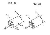
- Figs. 2A and 2B are schematic views showing the detection head 2 in the above-described optical encoder.
- the cable 3 is configured by bundling a plurality of optical fibers.
- the cable 3 is configured by bundling six receiver optical fibers 221 around a light source optical fiber 211. Tip end portions of the cables 3 are covered by a ferrule 25 to configure the detection head 2.
- a single-mode fiber is used as the light source optical fiber 211
- multi-mode fibers are used as the receiver optical fibers 221.
- the tip end of the light source optical fiber 211 configures a light source portion 21, and the tip ends of the receiver optical fibers 221 configure receiver portions 22, respectively.
- a mask 23 having transmission type diffraction gratings is attached to the front surfaces of the light source portion 21 and the receiver portions 22.
- Fig. 3 is a view showing in detail the mask 23.
- the four receiver portions 22 are placed respectively in upper left, upper right, lower left, and lower right places centered at the light source portion 21.
- the four receiver portions 22 are formed as a phase detection receiver portion 222 which detects phase of displacement.
- Two receiver portions 22 which are placed respectively in upper center and lower center places are formed as a posture monitor receiver portion 223 which also has a function of detecting the origin (zero).
- the mask 23 includes four transmission type phase detection diffraction gratings 231 and two posture monitor windows 232.
- the four transmission type phase detection diffraction gratings 231 and two posture monitor windows 232 are disposed so as to be located on the front surfaces of the phase detection receiver portion 222 and the posture monitor receiver portion 223, respectively.
- a central portion of the mask 23 which is located on the front surface of the light source portion 21 is configured so that light emitted from the light source portion 21 transmits therethrough as it is.
- the upper left, upper right, lower left, and lower right phase detection diffraction gratings 231 form phase gratings of a-, b-, ab-, and bb-phase having spatial phase relationships of 0°, 90°, 180°, and 270° at equal pitches, respectively.
- the phase detection receiver portions 222 are referred to as receiver portions 222A, 222B, 222AB, 222BB, respectively.
- the portion which is disposed in the positive direction of the Y-axis is denoted by 223Z, and that which is disposed in the negative direction of the Y-axis is denoted by 223ZB.
- the posture monitor receiver portions 223Z, 223ZB function also as a zero-point detecting portions.
- Fig. 4 is a view showing the attachment posture of the detection head 2 of the optical encoder of the first embodiment of the invention.
- the relative moving direction of the detection head 2 with respect to the scale 1 is indicated as the X direction (measurement axis direction)
- the direction which is parallel to the surface of the scale 1, and which is perpendicular to the X direction is indicated as the Y direction
- the direction which is perpendicular to the X and Y directions, i.e., that which is perpendicular to the surface of the scale 1 is indicated as the Z direction.
- the inclination between the scale 1 and the detection head 2 in the X-Z plane is indicated as the Pitch direction
- that in the Y-Z plane is indicated as the Roll direction
- that in the X-Y plane is indicated as the Yaw direction.
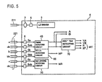
- FIG. 5 is a block diagram showing the configuration of the signal processing device 4 of the optical encoder of the first embodiment of the invention.
- the signal processing device 4 has, for example, an LD 6 as a light source to which a basal end portion of the light source optical fiber 211 is connected via an optical system 7.
- the LD 6 is driven by a LD driver 5 to emit coherent light.
- the coherent light is guided to the core of the light source optical fiber 211 via an optical system 7, and then irradiated from the light source portion 21 toward the scale 1.
- the signal processing device 4 further has six light receiving elements 8 to which basal end portions of the receiver optical fibers 221 are connected.
- the six light receiving elements 8 output phase signals Sa, Sab, Sb, Sbb having phases of 0°, 90°, 180°, and 270°, and posture monitor signals Sz, Szb, respectively.
- the phase signals Sa, Sab, Sb, Sbb are input to a phase detecting circuit 40 and a Pitch detecting circuit 60, and the posture monitor signals Sz, Szb are input to a Roll detecting circuit 50 which also has a function of detecting the origin.
- the phase detecting circuit 40 performs an arithmetic process to the phase signals Sa, Sab, Sb, Sbb to output quadrature differential signals A, B indicating the displacement of the detection head 2 with respect to the scale 1,
- the Pitch detecting circuit 60 performs an arithmetic process to the phase signals Sa, Sab, Sb, Sbb to output a posture monitor signal MP of the Pitch direction.
- the Roll detecting circuit 50 performs an arithmetic process to the posture monitor signals Sz, Szb to output a posture monitor signal MR of the Roll direction or output an origin signal corresponding to the origin position.
- An AGC/Yaw detecting circuit 70 performs an arithmetic process to the quadrature differential signals' A, B which are output from the phase detecting circuit 40, to output normalized quadrature differential signals VA, VB, and the Lissajous radius R of the quadrature differential signals A, B or a squaring value R 2 of the Lissajous radius as a posture monitor signal MY of the Yaw direction.
- Fig. 6 is a circuit diagram showing the configuration of the phase detecting circuit 40.
- the phase detecting circuit 40 has a current/voltage converter 41, a three-phase signal producer 42, and a quadrature differential signal producer 43,
- the current/voltage converter 41 is configured by current/voltage converting circuits 41A, 41B, 41AB, 41BB.
- the phase signals Sa, Sb, Sab, Sbb are supplied to the circuits, respectively.
- the three-phase signal producer 42 is configured by differential amplifying circuits 42A to 42C.
- the differential amplifying circuit 42A amplifies the difference between the phase signals Sa, Sab, and outputs a first differential signal DSa.
- the first differential signal DSa is obtained by taking the difference between the phase signal Sa having the phase of 0 degree and the phase signal Sab having the phase of 180 degrees.
- the first differential signal DSa is a signal which, when there is no phase deviation between the phase signals Sa, Sab, has the phase of 0 degree that is identical with a reference phase.
- the differential amplifying circuit 42B amplifies the difference between the phase signals Sb, Sbb, and outputs a second differential signal DSb.
- the second differential signal DSb is obtained by taking the difference between the phase signal Sb having the phase of 90 degrees and the phase signal Sbb having the phase of 270 degrees.
- the second differential signal DSb is a signal which, when there is no phase deviation between the phase signals Sb, Sbb, has the phase of 90 degrees with respect to the reference phase.
- the differential amplifying circuit 42C amplifies the difference between the phase signals Sb, Sbb, and outputs an inverted differential signal DSo.
- the inverted differential signal DSc is obtained as an inverted differential signal which is different in phase from the second differential signal DSb by 180 degrees.
- the inverted differential signal DSc is a signal having a phase or 270 degrees (i.e., -90 degrees) with respect to the reference phase. From the above, the three-phase differential signals DSa, DSb, DSc which are obtained in the three-phase signal producer 42 have a phase difference of 90 degrees with respect to each other.
- the quadrature differential signal producer 43 has differential amplifying circuit 43A, 43B and a gain adjusting section 44 which adjusts the gains of their outputs.
- the first differential signal DSa and the second differential signal DSb are input to the differential amplifying circuit 43A.
- the differential amplifying circuit 43A performs vector synthesis of the two input signals DSa, DSb to produce an A-phase signal. Since the signal DSa having a phase of 0 degree and the signal DSb having a phase of 90 degrees are vector synthesized, the A-phase signal is a signal having a phase difference of 45 degrees with respect to the reference phase.
- the first differential signal DSa and the inverted differential signal DSc are input to the differential amplifying circuit 43B.
- the differential amplifying circuit 43B performs vector synthesis of the two input signals DSa, DSc to produce a B-phase signal.
- the B-phase signal is a signal having a phase difference of 315 degrees (i.e., -45 degrees) with respect to the reference phase. In this way, the obtained A- and B-phase signals have a phase difference of 90 degrees.
- Fig. 7 is a circuit diagram showing the configuration of the Roll (and the origin) detecting circuit 50.
- the Roll detecting circuit 50 includes current/voltage converting circuits 51 and a differential amplifying circuit 52.
- the current/voltage converting circuits 51A, 51B amplify the posture monitor signals Sz, Szb which are obtained from light reception signals received by the posture monitor receiver portions 223Z, 223ZB respectively.
- the differential amplifying circuit 52 amplifies the difference between the amplified posture monitor signals Sz, Szb. When the intensities of the posture monitor signals Sz, Szb are equal to each other (at a position other than the origin), therefore, no signal is output from the differential amplifying circuit 52.
- the differential amplifying circuit 52 outputs the posture monitor signal MR corresponding to the rotation angle of the detection head 2 in the Roll direction.
- the posture monitor windows 232 have a large width, and the posture monitor signals Sz, Szb have a constant output value independent of the phase relationships of the detection head 2 and the gratings of the scare 1. Therefore, the rotation of the detection head 2 in the Roll direction can be detected without moving the detection head 2 with respect to the scale 1.
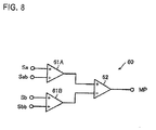
- Fig. 8 is a circuit diagram showing the configuration of the Pitch detecting circuit 60.
- the Pitch detecting circuit 60 includes adder circuits 61A, 61B and a differential amplifying circuit 62.
- the adder circuit 61A receives the phase signals Sa, Sab, and adds the signals together.
- the adder circuit 61B receives the phase signals Sb, Sbb, and adds the signals together.
- the differential amplifying circuit 62 amplifies the difference between the output of the adder circuit 61B and that of the adder circuit 61A, and outputs the posture monitor signal MP of the Pitch direction.
- the phase signals Sa, Sab are opposite in phase to each other, and hence a DC current is output from the adder circuit 61A. Similarly, a DC current is output also from the adder circuit 61B.
- the sum of the phase signals Sa, Sab is equal to that of the phase signals Sb, Sbb, therefore, no signal is output from the differential amplifying circuit 62.
- the receiver portions 222A, 222AB are disposed in the -X direction as viewed from the light source portion 21, and the receiver portions 222B, 222BB are disposed in the X direction as viewed from the light source portion 21.
- FIG. 9 is a circuit diagram showing the configuration of the AGC/Yaw detecting circuit 70.
- the AGC/Yaw detecting circuit 70 includes signal squaring blocks 71, 72, an adder circuit 73, a squaring root calculating block 74, divider circuits 75, 77, and amplifying circuits 76, 78.
- the quadrature differential signal A which is produced in the phase detecting circuit 40 is input to the signal squaring block 71.
- the quadrature differential signal B is input to the signal squaring block 72.
- the output signals of the signal squaring blocks 71, 72 are added together by the adder circuit 73.
- the squaring value R 2 of the Lissajous radius of the quadrature differential signals A, B is obtained.
- the squaring value is converted to the squaring root by the squaring root calculating block 74, whereby the Lissajous radius R of the quadrature differential signals A, B is obtained.
- the Lissajous radius R or the squaring value R 2 thereof is output as the posture monitor signal MY of the Yaw direction.
- the quadrature differential signal A is normalized by the Lissajous radius R, amplified by the amplifying circuit 76, and output as the normalized quadrature differential signal VA.
- the quadrature differential signal B is normalized by the Lissajous radius R, amplified by the amplifying circuit 78, and output as the normalized quadrature differential signal VB.
- the optical encoder of the embodiment detects the contraction of the Lissajous radius due to the rotation of the detection head 2 in the Yaw direction, and detects the Yaw rotation angle ⁇ yaw.
- the rotation in the Yaw direction may be adjusted so that the size of the Lissajous radius has the maximum value, or the Yaw rotation angle ⁇ yaw may be adjusted by previously detecting the size of the Lissajous radius in the best alignment state, setting the detected size as a reference value, and comparing the obtained Lissajous radius with the reference value.
- Fig. 10 shows the manner of contraction of the Lissajous radius in accordance with the rotation of the detection head 2 in the Yaw direction.
- Fig. 10 is a graph showing relationships between the rotation angle in the Yaw direction and the size of the Lissajous radius. In the figure, the ordinate indicates the size of the Lissajous radius, and the abscissa indicates the rotation angle in the Yaw direction.
- Fig. 10 shows the manner of contraction of the Lissajous radius in accordance with the rotation of the detection head 2 in the Yaw direction.
- Fig. 10 is a graph showing relationships between the rotation angle in the Yaw direction and the size of the Lissajous radius. In the figure, the ordinate indicates the size of the Lissajous radius, and the abscissa indicates the rotation angle in the Yaw direction.
- the 10 shows results of simulations in the case where the distance h between the scale 1 and the detection head 2 is 200 ⁇ m, and the pitches P of the optical grating of the scale 1 and the phase detection diffraction gratings 231 are 4 ⁇ m the center-to-center distance of the receiver portions 22 is 200 ⁇ m, and the detection head 2 is rotated about the light source portion 21 in the Yaw direction.
- the intensity I A of the A-phase signal and the intensity I B of the B-phase signal at the length measuring position x are vindicated as follows:
- I A X F ⁇ yaw ⁇ sin 2 ⁇ ⁇ ⁇ x ⁇ 2 P + ⁇
- I B X F ⁇ yaw ⁇ cos 2 ⁇ ⁇ ⁇ x ⁇ 2 P + ⁇
- H( ⁇ yaw) indicates deterioration of the signal intensity of each receiver portion due to the rotation of the detection head 2 in the Yaw direction, and depends on the distance h between the scale 1 and the detection head 2, and the interference fringe period P
- G( ⁇ yaw) indicates deterioration of the signal intensity of the differential signal in opposite phase, and depends on the phase difference of phase signals S detected from a combination of receiver portions which are designed so as to receive the phase signals S in opposite phase, such as receiver portions 222A, 222AB, or the receiver portions 222B, 222BB.
- the maximum value of the posture monitor signal MY is detected, thereby enabling the adjustment of misalignment in the Yaw direction to be performed.
- the Lissajous radius R of the quadrature differential signals A, B or a squaring value R 2 of the radius is used as the posture monitor signal MY of the Yaw direction.
- the Lissajous radius R is approximated to a characteristic function, and an inverse function or differential function of the characteristic function is used. This can improve the adjustment resolution.
- the relationship between the rotation angle and the size of the Lissajous radius can be Gaussian approximated.
- the logarithm of the inverse function is used, therefore, the adjustment resolution in the region of the vicinity of 0.0° of the Yaw rotation angle (the vicinity of the best alignment) is improved.
- an inverse function converting block 79 which performs the inverse function conversion to the Lissajous radius R is disposed in the AGC/Yaw detecting circuit 70, and the output of the block is set as a posture monitor signal MY' of the Yaw direction.
- the Yaw rotation is adjusted by using the posture monitor signal MY', the adjustment work is further facilitated.
- MY' is calculated in the following manner. Namely, the relationship between the Yaw rotation angle ⁇ and the size of the Lissajous radius such as shown in Fig. 10 is obtained. Next, normalization is performed on the characteristics, and the maximum value of the characteristics is set to 1. The size of the normalized radius is indicated by y( ⁇ ), and the following calculation is performed.
- MY ⁇ Value of allowable level - Y ⁇
- Fig. 12 shows relationships between MY' calculated by using Exps. 4 and 5 above, and the Yaw rotation angle ⁇ .
- the example of Fig. 12 is set so that MY' has a positive value in a predetermined alignment allowable region.
- MY' uniformly changes also in a range where the Yaw rotation angle is in the vicinity of 0°, and therefore more accurate detection of the Yaw rotation angle, and an easy adjusting work can be performed.
- the Yaw adjustment may be performed in the final step.
- Fig. 13 is a diagram showing an example in which the arithmetic process is realized by software using a microcomputer or a PC.
- the signal processing device 4 includes an A/D converter 80 and a calculating circuit 90, in place of the phase detecting circuit 40, the Pitch detecting circuit 60, the Roll detecting circuit 50, and the AGC/Yaw detecting circuit 70.
- the calculating circuit 90 is connected to an external PC 10.
- the A/D converter 80 converts the phase signals Sa, Sab, Sb, Sbb, and the posture monitor signals Sz, Szb to digital signals, and supplies the digital signals to the calculating circuit 90.
- the calculating circuit 90 calculates the quadrature differential signals A, B, the posture monitor signals MP. MR, the normalized quadrature differential signals VA, VB, the Lissajous radius R, and the like from the phase signals and posture monitor signals which are converted to digital signals, and supplies them to the PC 10.
- the phase signals and the posture monitor signals may be directly transmitted to the PC 10, and the PC 10 may calculate the posture monitor signals and the like.
- the arithmetic process is realized by software.
- software can be mounted with firmware or the like. It is possible to very economically provide an optical encoder in which misalignment detection and misalignment adjustment of the detection head is easily performed.
Landscapes
- Physics & Mathematics (AREA)
- General Physics & Mathematics (AREA)
- Optical Transform (AREA)
Abstract
Description
- The present invention described herein relates to the field of optical encoders, and a misalignment detection and an adjustment method associated therewith.
- As one of optical encoders of this kind, is known an optical encoder which uses a linear scale having diffraction gratings. In such an optical encoder, coherent light emitted from the Light source is diffracted by the linear scale, and an interference fringe having position information is generated. When the interference fringe is phase detected, a length in the direction along the scale can be measured (see Patent Reference 1). In an optical encoder of this kind, conventionally, adjustment of misalignment of a detection head is performed by adjusting the relative positional relationship between the detection head and the scale while moving the detection head along the scale and viewing an output Lissajous signal. In this case, with respect to a detection head having a relatively large size, a mechanical reference for the scale can be easily set, and, when the detection head is to be mounted, the best alignment state can be ensured to some extent. With respect to a detection head having a relatively small size (
Patent References 1 and 2), however, a mechanical reference is hardly set, and, when the detection head is to be mounted, a work of adjusting misalignment is necessary. - In the case where a space for performing adjustment of misalignment cannot be easily ensured, such as the case where an optical encoder is to be incorporated into a stage of a three-dimensional measuring apparatus, the above-discussed method is hardly performed. In order to comply with such a case, a method of performing adjustment of misalignment in a resting state (i.e., without moving a detection head along a scale) has been proposed (Patent Reference 3).
-
- [Patent Reference 1]
JP-A-2004-53605 - [Patent Reference 2]
JP-A-2008-39602 - [Patent Reference 3]
JP-A-2007-232681 -
Patent Reference 3 proposes a method in which signals produced based on light received by a plurality of light receiving sections that are disposed in a detection head are compared with each other, thereby detecting the rotation amounts of the detection head in Pitch and Roll directions. In the patent reference, however, detection of the rotation amount in Yaw direction in a resting state is not proposed. The detection of the rotation amount in Yaw direction remains to be performed in a conventional method. - Exemplary embodiments of the invention provide an optical encoder and a method of adjusting misalignment of a detection head in which misalignment of the detection head can be easily adjusted.
- An optical encoder according to the invention comprises:
- a scale having diffraction gratings formed at predetermined pitches in a measurement axis direction;
- a detection head relatively movable with respect to the scale, the detection head including a light source portion configured to irradiate the scale with light, and a plurality of receiver portions configured to receive light reflected by or transmitted through the diffraction gratings of the scale, at different phases; and
- a signal processing device configured to perform signal processing to light reception signals output from the receiver portions of the detection head, to produce quadrature differential signals, wherein
- the signal processing device is configured to calculate posture monitor signals corresponding to a Lissajous radius of the quadrature differential signals in order to detect misalignment of the detection head with respect to the scale.
- According to the invention, the Lissajous radius can be obtained and the rotation angle of the detection head in the Yaw direction can be detected without moving the detection head or the scale.
- In the optical encoder according to one embodiment of the invention, the plurality of receiver portions may be four receiver portions placed respectively in upper left, upper right, lower left, and lower tight places centered at the light source portion, the four receiver portions being configured to receive light reflected by or transmitted through diffraction gratings of the scale that are different in spatial phase by 90° from each other, and the signal processing device may be configured to perform an arithmetic process to the light reception signals output from the four receiver portions to produce the quadrature differential signals.
- A method of adjusting misalignment according to one embodiment of the invention, comprises:
- adjusting misalignment of the detection head in a Yaw direction with respect to the scale so that a monitor signal has a maximum value, the monitor signal being the Lissajous radius of the quadrature differential signals output from the signal processing device, or a squaring value of the Lissajous radius.
- Alternatively, in the optical encoder according to another embodiment of the invention, the signal processing device may be configured to approximate the Lissajous radius or a squaring value of the Lissajous radius to a characteristic function, and to obtain an inverse function or differential function of the characteristic function, as a monitor signal.
- A method of adjusting misalignment according to the other embodiment of the invention, comprises:
- adjusting misalignment of the detection head in a Yaw direction with respect to the scale so that the monitor signal is within an allowable range.
- According to the invention, it is possible to provide an optical encoder and a method of adjusting misalignment of a detection head in which misalignment of the detection head can be easily adjusted.
-
-
Fig. 1 is a view showing a configuration of an optical encoder of a first embodiment of the invention; -
Figs. 2A and 2B are schematic views each showing a detection head of the optical encoder; -
Fig. 3 is a view showing a mask of the optical encoder; -
Fig. 4 is a view showing an attachment posture of the detection head of the optical encoder; -
Fig. 5 is a block diagram showing a configuration of a signal professing device of the optical encoder;' -
Fig. 6 is a circuit diagram showing a phase detecting circuit of the optical encoder; -
Fig. 7 is a circuit diagram showing a Roll detecting circuit of the optical encoder; -
Fig. 8 is a circuit diagram showing a Pitch detecting circuit of the optical encoder; -
Fig. 9 is a circuit diagram showing a AGC/Yaw detecting circuit of the optical encoder; -
Fig. 10 is a graph showing a relationship between a size of the Lissajous radius and a rotation angle in a Yaw direction of the optical encoder, -
Fig. 11 is a block diagram showing a configuration of a part of a signal processing device in an optical encoder according to a second embodiment of the invention. -
Fig. 12 is a graph showing a relationship between a posture monitor signal and a Yaw rotation angle θ; and -
Fig. 13 is a block diagram showing a configuration of a signal processing device in an optical encoder according to a third embodiment of the invention. - Next, an optical encoder of a first embodiment of the invention will be described in detail with reference to the drawings.
-
Fig. 1 is a view showing the configuration of the optical encoder of the first embodiment of the invention. The optical encoder of the first embodiment of the invention includes: ascale 1 in which reflection type diffraction gratings are formed at predetermined pitches in the measurement axis direction; and adetection head 2 that is opposed to the surface of thescale 1 in which the diffraction gratings are formed, through a predetermined gap, and that is relatively movable with respect to thescale 1. Thedetection head 2 is connected to a signal processing device 4 through acable 3. -
Figs. 2A and 2B are schematic views showing thedetection head 2 in the above-described optical encoder. In the embodiment, thecable 3 is configured by bundling a plurality of optical fibers. Thecable 3 is configured by bundling six receiveroptical fibers 221 around a light sourceoptical fiber 211. Tip end portions of thecables 3 are covered by aferrule 25 to configure thedetection head 2. For example, a single-mode fiber is used as the light sourceoptical fiber 211, and multi-mode fibers are used as the receiveroptical fibers 221. As shown inFig. 2A , the tip end of the light sourceoptical fiber 211 configures alight source portion 21, and the tip ends of the receiveroptical fibers 221 configurereceiver portions 22, respectively. As shown inFig. 2B , amask 23 having transmission type diffraction gratings is attached to the front surfaces of thelight source portion 21 and thereceiver portions 22. -
Fig. 3 is a view showing in detail themask 23. Namely, fourreceiver portions 22 are placed respectively in upper left, upper right, lower left, and lower right places centered at thelight source portion 21. The fourreceiver portions 22 are formed as a phase detection receiver portion 222 which detects phase of displacement. Tworeceiver portions 22 which are placed respectively in upper center and lower center places are formed as a posture monitor receiver portion 223 which also has a function of detecting the origin (zero). Themask 23 includes four transmission type phasedetection diffraction gratings 231 and twoposture monitor windows 232. The four transmission type phasedetection diffraction gratings 231 and twoposture monitor windows 232 are disposed so as to be located on the front surfaces of the phase detection receiver portion 222 and the posture monitor receiver portion 223, respectively. A central portion of themask 23 which is located on the front surface of thelight source portion 21 is configured so that light emitted from thelight source portion 21 transmits therethrough as it is. - The upper left, upper right, lower left, and lower right phase
detection diffraction gratings 231 form phase gratings of a-, b-, ab-, and bb-phase having spatial phase relationships of 0°, 90°, 180°, and 270° at equal pitches, respectively. Hereinafter, the phase detection receiver portions 222 are referred to asreceiver portions monitor receiver portions 223Z, 223ZB function also as a zero-point detecting portions. -
Fig. 4 is a view showing the attachment posture of thedetection head 2 of the optical encoder of the first embodiment of the invention. In the description, the relative moving direction of thedetection head 2 with respect to thescale 1 is indicated as the X direction (measurement axis direction), the direction which is parallel to the surface of thescale 1, and which is perpendicular to the X direction is indicated as the Y direction, and the direction which is perpendicular to the X and Y directions, i.e., that which is perpendicular to the surface of thescale 1 is indicated as the Z direction. The inclination between thescale 1 and thedetection head 2 in the X-Z plane is indicated as the Pitch direction, that in the Y-Z plane is indicated as the Roll direction, and that in the X-Y plane is indicated as the Yaw direction. - Next, the signal processing device 4 of the optical encoder will be described.
Fig. 5 is a block diagram showing the configuration of the signal processing device 4 of the optical encoder of the first embodiment of the invention. - The signal processing device 4 has, for example, an
LD 6 as a light source to which a basal end portion of the light sourceoptical fiber 211 is connected via anoptical system 7. TheLD 6 is driven by aLD driver 5 to emit coherent light. The coherent light is guided to the core of the light sourceoptical fiber 211 via anoptical system 7, and then irradiated from thelight source portion 21 toward thescale 1. - The signal processing device 4 further has six light receiving elements 8 to which basal end portions of the receiver
optical fibers 221 are connected. The six light receiving elements 8 output phase signals Sa, Sab, Sb, Sbb having phases of 0°, 90°, 180°, and 270°, and posture monitor signals Sz, Szb, respectively. The phase signals Sa, Sab, Sb, Sbb are input to aphase detecting circuit 40 and aPitch detecting circuit 60, and the posture monitor signals Sz, Szb are input to aRoll detecting circuit 50 which also has a function of detecting the origin. Thephase detecting circuit 40 performs an arithmetic process to the phase signals Sa, Sab, Sb, Sbb to output quadrature differential signals A, B indicating the displacement of thedetection head 2 with respect to thescale 1, ThePitch detecting circuit 60 performs an arithmetic process to the phase signals Sa, Sab, Sb, Sbb to output a posture monitor signal MP of the Pitch direction. TheRoll detecting circuit 50 performs an arithmetic process to the posture monitor signals Sz, Szb to output a posture monitor signal MR of the Roll direction or output an origin signal corresponding to the origin position. An AGC/Yaw detecting circuit 70 performs an arithmetic process to the quadrature differential signals' A, B which are output from thephase detecting circuit 40, to output normalized quadrature differential signals VA, VB, and the Lissajous radius R of the quadrature differential signals A, B or a squaring value R2 of the Lissajous radius as a posture monitor signal MY of the Yaw direction. -
Fig. 6 is a circuit diagram showing the configuration of thephase detecting circuit 40. - The
phase detecting circuit 40 has a current/voltage converter 41, a three-phase signal producer 42, and a quadraturedifferential signal producer 43, - The current/
voltage converter 41 is configured by current/voltage converting circuits 41A, 41B, 41AB, 41BB. The phase signals Sa, Sb, Sab, Sbb are supplied to the circuits, respectively. The three-phase signal producer 42 is configured bydifferential amplifying circuits 42A to 42C. - The
differential amplifying circuit 42A amplifies the difference between the phase signals Sa, Sab, and outputs a first differential signal DSa. The first differential signal DSa is obtained by taking the difference between the phase signal Sa having the phase of 0 degree and the phase signal Sab having the phase of 180 degrees. The first differential signal DSa is a signal which, when there is no phase deviation between the phase signals Sa, Sab, has the phase of 0 degree that is identical with a reference phase. - Similarly, the
differential amplifying circuit 42B amplifies the difference between the phase signals Sb, Sbb, and outputs a second differential signal DSb. The second differential signal DSb is obtained by taking the difference between the phase signal Sb having the phase of 90 degrees and the phase signal Sbb having the phase of 270 degrees. The second differential signal DSb is a signal which, when there is no phase deviation between the phase signals Sb, Sbb, has the phase of 90 degrees with respect to the reference phase. - In a same manner as the
differential amplifying circuit 42B, the differential amplifying circuit 42C amplifies the difference between the phase signals Sb, Sbb, and outputs an inverted differential signal DSo. The inverted differential signal DSc is obtained as an inverted differential signal which is different in phase from the second differential signal DSb by 180 degrees. Namely, the inverted differential signal DSc is a signal having a phase or 270 degrees (i.e., -90 degrees) with respect to the reference phase. From the above, the three-phase differential signals DSa, DSb, DSc which are obtained in the three-phase signal producer 42 have a phase difference of 90 degrees with respect to each other. - The quadrature
differential signal producer 43 hasdifferential amplifying circuit gain adjusting section 44 which adjusts the gains of their outputs. The first differential signal DSa and the second differential signal DSb are input to thedifferential amplifying circuit 43A. Thedifferential amplifying circuit 43A performs vector synthesis of the two input signals DSa, DSb to produce an A-phase signal. Since the signal DSa having a phase of 0 degree and the signal DSb having a phase of 90 degrees are vector synthesized, the A-phase signal is a signal having a phase difference of 45 degrees with respect to the reference phase. - Similarly, the first differential signal DSa and the inverted differential signal DSc are input to the
differential amplifying circuit 43B. Thedifferential amplifying circuit 43B performs vector synthesis of the two input signals DSa, DSc to produce a B-phase signal. Similarly with the A-phase signal, since the signal DSa having a phase of 0 degree and the signal DSc having a phase of 270 degrees (-90 degrees) are vector synthesized, the B-phase signal is a signal having a phase difference of 315 degrees (i.e., -45 degrees) with respect to the reference phase. In this way, the obtained A- and B-phase signals have a phase difference of 90 degrees. -
Fig. 7 is a circuit diagram showing the configuration of the Roll (and the origin) detectingcircuit 50. TheRoll detecting circuit 50 includes current/voltage converting circuits 51 and adifferential amplifying circuit 52. The current/voltage converting circuits monitor receiver portions 223Z, 223ZB respectively. Thedifferential amplifying circuit 52 amplifies the difference between the amplified posture monitor signals Sz, Szb. When the intensities of the posture monitor signals Sz, Szb are equal to each other (at a position other than the origin), therefore, no signal is output from thedifferential amplifying circuit 52. In this configuration, in the case where thedetection head 2 is rotated in the Roll direction, there is a difference between the distance between the posturemonitor receiver portion 223Z and thescale 1, and that between the posture monitor receiver portion 223ZB and thescale 1. and hence an intensity difference is produced between the posture monitor signals Sz, Szb. Therefore, thedifferential amplifying circuit 52 outputs the posture monitor signal MR corresponding to the rotation angle of thedetection head 2 in the Roll direction. The posture monitorwindows 232 have a large width, and the posture monitor signals Sz, Szb have a constant output value independent of the phase relationships of thedetection head 2 and the gratings of thescare 1. Therefore, the rotation of thedetection head 2 in the Roll direction can be detected without moving thedetection head 2 with respect to thescale 1. -
Fig. 8 is a circuit diagram showing the configuration of thePitch detecting circuit 60. ThePitch detecting circuit 60 includesadder circuits differential amplifying circuit 62. Theadder circuit 61A receives the phase signals Sa, Sab, and adds the signals together. Theadder circuit 61B receives the phase signals Sb, Sbb, and adds the signals together. Thedifferential amplifying circuit 62 amplifies the difference between the output of theadder circuit 61B and that of theadder circuit 61A, and outputs the posture monitor signal MP of the Pitch direction. - In the configuration, the phase signals Sa, Sab are opposite in phase to each other, and hence a DC current is output from the
adder circuit 61A. Similarly, a DC current is output also from theadder circuit 61B. In the case where the sum of the phase signals Sa, Sab is equal to that of the phase signals Sb, Sbb, therefore, no signal is output from thedifferential amplifying circuit 62. In the embodiment, thereceiver portions 222A, 222AB are disposed in the -X direction as viewed from thelight source portion 21, and thereceiver portions 222B, 222BB are disposed in the X direction as viewed from thelight source portion 21. When the rotation in the Pitch direction is produced, therefore, a DC current corresponding to the rotation angle in the Pitch direction is output between the output of theadder circuit 61A and that of the adder circuit 61 B. Also in this case, it is not necessary to change (move) the positional relationship between thedetection head 2 and thescale 1. - Next, the AGC/
Yaw detecting circuit 70 will be described.Fig. 9 is a circuit diagram showing the configuration of the AGC/Yaw detecting circuit 70. The AGC/Yaw detecting circuit 70 includes signal squaring blocks 71, 72, anadder circuit 73, a squaringroot calculating block 74,divider circuits circuits phase detecting circuit 40 is input to thesignal squaring block 71. Similarly, the quadrature differential signal B is input to thesignal squaring block 72. The output signals of the signal squaring blocks 71, 72 are added together by theadder circuit 73. As a result, the squaring value R2 of the Lissajous radius of the quadrature differential signals A, B is obtained. The squaring value is converted to the squaring root by the squaringroot calculating block 74, whereby the Lissajous radius R of the quadrature differential signals A, B is obtained. The Lissajous radius R or the squaring value R2 thereof is output as the posture monitor signal MY of the Yaw direction. In thedivider circuit 75, the quadrature differential signal A is normalized by the Lissajous radius R, amplified by the amplifyingcircuit 76, and output as the normalized quadrature differential signal VA. In thedivider circuit 77, similarly, the quadrature differential signal B is normalized by the Lissajous radius R, amplified by the amplifyingcircuit 78, and output as the normalized quadrature differential signal VB. - In the configuration, when the
detection head 2 is rotated in the Yaw direction, the signals which are received by thereceiver portions 22 are deteriorated, and the Lissajous radius is contracted. The optical encoder of the embodiment detects the contraction of the Lissajous radius due to the rotation of thedetection head 2 in the Yaw direction, and detects the Yaw rotation angle θyaw. In the configuration, the rotation in the Yaw direction may be adjusted so that the size of the Lissajous radius has the maximum value, or the Yaw rotation angle θyaw may be adjusted by previously detecting the size of the Lissajous radius in the best alignment state, setting the detected size as a reference value, and comparing the obtained Lissajous radius with the reference value. -
Fig. 10 shows the manner of contraction of the Lissajous radius in accordance with the rotation of thedetection head 2 in the Yaw direction.Fig. 10 is a graph showing relationships between the rotation angle in the Yaw direction and the size of the Lissajous radius. In the figure, the ordinate indicates the size of the Lissajous radius, and the abscissa indicates the rotation angle in the Yaw direction.Fig. 10 shows results of simulations in the case where the distance h between thescale 1 and thedetection head 2 is 200 µm, and the pitches P of the optical grating of thescale 1 and the phasedetection diffraction gratings 231 are 4 µm the center-to-center distance of thereceiver portions 22 is 200 µm, and thedetection head 2 is rotated about thelight source portion 21 in the Yaw direction. - When the scale period is indicated by P, the signal period due to diffraction interference is indicated by P/2, and the initial phase is Φ, the intensity IA of the A-phase signal and the intensity IB of the B-phase signal at the length measuring position x are vindicated as follows:
-

-

- where F(θyaw) indicates the signal amplitude, and can be expressed in the following manner:
-

where H(θyaw) indicates deterioration of the signal intensity of each receiver portion due to the rotation of thedetection head 2 in the Yaw direction, and depends on the distance h between thescale 1 and thedetection head 2, and the interference fringe period P, and G(θyaw) indicates deterioration of the signal intensity of the differential signal in opposite phase, and depends on the phase difference of phase signals S detected from a combination of receiver portions which are designed so as to receive the phase signals S in opposite phase, such asreceiver portions 222A, 222AB, or thereceiver portions 222B, 222BB. - From
Fig. 10 , it is seen that, as the rotation angle in the Yaw direction is lager, the size of the Lissajous radius R is more reduced. When the Yaw rotation angle is increase from 0.1° to 0.3°, particularly, the size of the Lissajous radius R is reduced to about one forth. In the range of the Yaw rotation angle from 0.0° to 0.1°, the change of the Lissajous radius R is relatively small, but sufficiently large as a signal, and hence can be used as the posture monitor signal MY. - According to the configuration, while the
detection head 2 is rotated in the Yaw direction without relatively moving thescale 1 and thedetection head 2 in the direction of the measurement axis, the maximum value of the posture monitor signal MY is detected, thereby enabling the adjustment of misalignment in the Yaw direction to be performed. - In the first embodiment, the Lissajous radius R of the quadrature differential signals A, B or a squaring value R2 of the radius is used as the posture monitor signal MY of the Yaw direction. In the second embodiment, for example, the Lissajous radius R is approximated to a characteristic function, and an inverse function or differential function of the characteristic function is used. This can improve the adjustment resolution.
- As shown in
Fig. 10 , for example, the relationship between the rotation angle and the size of the Lissajous radius can be Gaussian approximated. When the logarithm of the inverse function is used, therefore, the adjustment resolution in the region of the vicinity of 0.0° of the Yaw rotation angle (the vicinity of the best alignment) is improved. - As shown in
Fig. 11 , therefore, an inversefunction converting block 79 which performs the inverse function conversion to the Lissajous radius R is disposed in the AGC/Yaw detecting circuit 70, and the output of the block is set as a posture monitor signal MY' of the Yaw direction. When the Yaw rotation is adjusted by using the posture monitor signal MY', the adjustment work is further facilitated. - Hereinafter, taking the logarithmic conversion as an example of the inverse function conversion, the adjustment work in the embodiment will be described. In the example, MY' is calculated in the following manner. Namely, the relationship between the Yaw rotation angle θ and the size of the Lissajous radius such as shown in
Fig. 10 is obtained. Next, normalization is performed on the characteristics, and the maximum value of the characteristics is set to 1. The size of the normalized radius is indicated by y(θ), and the following calculation is performed. -

-

-
Fig. 12 shows relationships between MY' calculated by using Exps. 4 and 5 above, and the Yaw rotation angle θ. The example ofFig. 12 is set so that MY' has a positive value in a predetermined alignment allowable region. In the configuration, as shown inFig. 12 , MY' uniformly changes also in a range where the Yaw rotation angle is in the vicinity of 0°, and therefore more accurate detection of the Yaw rotation angle, and an easy adjusting work can be performed. - In the adjustment method in which, as in the embodiment, an alignment allowable region is set and then it is determined whether the posture is within the alignment allowable region or not, unlike in the adjusting method in which the squaring value R2 of the quadrature differential signals A, B is determined, normalization must be performed on the Lissajous radius. This is because, when normalization is not performed on the Lissajous radius, the alignment allowable region changes in accordance with the sizes of the
receiver portions 22 and the distance between thelight source portion 21 and thescale 1. - In this case, after the Roll adjustment and the Pitch adjustment (either of which may be first performed) are ended, the Yaw adjustment may be performed in the final step.
-
Fig. 13 is a diagram showing an example in which the arithmetic process is realized by software using a microcomputer or a PC. - Namely, the signal processing device 4 includes an A/
D converter 80 and a calculatingcircuit 90, in place of thephase detecting circuit 40, thePitch detecting circuit 60, theRoll detecting circuit 50, and the AGC/Yaw detecting circuit 70. The calculatingcircuit 90 is connected to anexternal PC 10. - The A/
D converter 80 converts the phase signals Sa, Sab, Sb, Sbb, and the posture monitor signals Sz, Szb to digital signals, and supplies the digital signals to the calculatingcircuit 90. The calculatingcircuit 90 calculates the quadrature differential signals A, B, the posture monitor signals MP. MR, the normalized quadrature differential signals VA, VB, the Lissajous radius R, and the like from the phase signals and posture monitor signals which are converted to digital signals, and supplies them to thePC 10. Alternatively, the phase signals and the posture monitor signals may be directly transmitted to thePC 10, and thePC 10 may calculate the posture monitor signals and the like. - In the embodiment, the arithmetic process is realized by software. With respect to an optical encoder in which a microcomputer is used in the signal processing device 4, or that in which the phase signals and the posture monitor signals are supplied to the
PC 10, therefore, such software can be mounted with firmware or the like. It is possible to very economically provide an optical encoder in which misalignment detection and misalignment adjustment of the detection head is easily performed.
Claims (5)
- An optical encoder comprising:a scale having diffraction gratings formed at predetermined pitches in a measurement axis direction;a detection head relatively movable with respect to the scale, the detection head including a light source portion configured to irradiate the scale with light, and a plurality of receiver portions configured to receive light reflected by or transmitted through the diffraction gratings of the scale, at different phases; anda signal processing device configured to perform signal processing to light reception signals output from the receiver portions of the detection head, to produce quadrature differential signals, whereinthe signal processing device is configured to calculate posture monitor signals corresponding to a Lissajous radius of the quadrature differential signals in order to detect misalignment of the detection head with respect to the scale.
- The optical encoder according to claim 1, wherein
the plurality of receiver portions are four receiver portions placed respectively in upper left, upper right, lower left, and lower right places centered at the light source portion, the four receiver portions being configured to receive light reflected by or transmitted through diffraction gratings of the scale that are different in spatial phase by 90° from each other, and
the signal processing device is configured to performs an arithmetic process to the light reception signals output from the four receiver portions to produce the quadrature differential signals. - The optical encoder according to claim 1 or 2, wherein
the signal processing device is configured to approximate the Lissajous radius or a squaring value of the Lissajous radius to a characteristic function, and to obtain an inverse function or differential function of the characteristic function, as a monitor signal. - A method of adjusting misalignment of a detection head of an optical encoder according to claim 1 or 2, comprising:adjusting misalignment of the detection head in a Yaw direction with respect to the scale so that a monitor signal has a maximum value, the monitor signal being the Lissajous radius of the quadrature differential signals output from the signal processing device, or a squaring value of the Lissajous radius.
- A method of adjusting misalignment of a detection head of an optical encoder according to claim 3, comprising:adjusting misalignment of the detection head in a Yaw direction with respect to the scale so that the monitor signal is within an allowable range.
Applications Claiming Priority (1)
| Application Number | Priority Date | Filing Date | Title |
|---|---|---|---|
| JP2011014897 | 2011-01-27 |
Publications (3)
| Publication Number | Publication Date |
|---|---|
| EP2482040A2 true EP2482040A2 (en) | 2012-08-01 |
| EP2482040A3 EP2482040A3 (en) | 2014-08-27 |
| EP2482040B1 EP2482040B1 (en) | 2019-06-05 |
Family
ID=45524438
Family Applications (1)
| Application Number | Title | Priority Date | Filing Date |
|---|---|---|---|
| EP12152700.6A Active EP2482040B1 (en) | 2011-01-27 | 2012-01-26 | Optical Encoder with Misalignment Detection and Adjustment Method Associated Therewith |
Country Status (4)
| Country | Link |
|---|---|
| US (1) | US8895911B2 (en) |
| EP (1) | EP2482040B1 (en) |
| JP (2) | JP6069653B2 (en) |
| CN (1) | CN102620762B (en) |
Cited By (2)
| Publication number | Priority date | Publication date | Assignee | Title |
|---|---|---|---|---|
| CN104482949A (en) * | 2014-12-29 | 2015-04-01 | 哈尔滨工业大学 | Precise code zero offset and amplitude self-adaptation compensation method of optical-electricity encoder |
| US10197589B2 (en) | 2014-02-28 | 2019-02-05 | Pgs Geophysical As | Displacement sensor device and system |
Families Citing this family (40)
| Publication number | Priority date | Publication date | Assignee | Title |
|---|---|---|---|---|
| JP6069653B2 (en) * | 2011-01-27 | 2017-02-01 | 株式会社ミツトヨ | Photoelectric encoder and alignment adjustment method thereof |
| US9542016B2 (en) | 2012-09-13 | 2017-01-10 | Apple Inc. | Optical sensing mechanisms for input devices |
| US9753436B2 (en) | 2013-06-11 | 2017-09-05 | Apple Inc. | Rotary input mechanism for an electronic device |
| CN109634447B (en) | 2013-08-09 | 2022-04-19 | 苹果公司 | Tactile switch for electronic devices |
| JP6369042B2 (en) * | 2013-11-05 | 2018-08-08 | 日本精工株式会社 | Optical encoder unit and optical encoder |
| WO2015122885A1 (en) | 2014-02-12 | 2015-08-20 | Bodhi Technology Ventures Llc | Rejection of false turns of rotary inputs for electronic devices |
| US9797752B1 (en) | 2014-07-16 | 2017-10-24 | Apple Inc. | Optical encoder with axially aligned sensor |
| US10190891B1 (en) | 2014-07-16 | 2019-01-29 | Apple Inc. | Optical encoder for detecting rotational and axial movement |
| US9797753B1 (en) * | 2014-08-27 | 2017-10-24 | Apple Inc. | Spatial phase estimation for optical encoders |
| US10066970B2 (en) | 2014-08-27 | 2018-09-04 | Apple Inc. | Dynamic range control for optical encoders |
| US10599101B2 (en) | 2014-09-02 | 2020-03-24 | Apple Inc. | Wearable electronic device |
| KR101940943B1 (en) | 2015-03-05 | 2019-01-21 | 애플 인크. | Optical encoder with direction dependent optical properties |
| WO2016144919A1 (en) | 2015-03-08 | 2016-09-15 | Apple Inc. | Compressible seal for rotatable and translatable input mechanisms |
| US9952682B2 (en) | 2015-04-15 | 2018-04-24 | Apple Inc. | Depressible keys with decoupled electrical and mechanical functionality |
| DE112016001860T5 (en) | 2015-04-22 | 2018-01-18 | Faro Technologies, Inc. | Indexed optical encoder |
| US10018966B2 (en) | 2015-04-24 | 2018-07-10 | Apple Inc. | Cover member for an input mechanism of an electronic device |
| US9891651B2 (en) | 2016-02-27 | 2018-02-13 | Apple Inc. | Rotatable input mechanism having adjustable output |
| US10551798B1 (en) | 2016-05-17 | 2020-02-04 | Apple Inc. | Rotatable crown for an electronic device |
| US10061399B2 (en) | 2016-07-15 | 2018-08-28 | Apple Inc. | Capacitive gap sensor ring for an input device |
| US10019097B2 (en) | 2016-07-25 | 2018-07-10 | Apple Inc. | Force-detecting input structure |
| US10664074B2 (en) | 2017-06-19 | 2020-05-26 | Apple Inc. | Contact-sensitive crown for an electronic watch |
| JP2017161553A (en) * | 2017-06-22 | 2017-09-14 | 株式会社リコー | Rotation angle detector, motor system, image processing device, and rotation angle detection method |
| US10962935B1 (en) | 2017-07-18 | 2021-03-30 | Apple Inc. | Tri-axis force sensor |
| US11360440B2 (en) | 2018-06-25 | 2022-06-14 | Apple Inc. | Crown for an electronic watch |
| US11561515B2 (en) | 2018-08-02 | 2023-01-24 | Apple Inc. | Crown for an electronic watch |
| US12259690B2 (en) | 2018-08-24 | 2025-03-25 | Apple Inc. | Watch crown having a conductive surface |
| CN209560398U (en) | 2018-08-24 | 2019-10-29 | 苹果公司 | digital watch |
| US11181863B2 (en) | 2018-08-24 | 2021-11-23 | Apple Inc. | Conductive cap for watch crown |
| US11194298B2 (en) | 2018-08-30 | 2021-12-07 | Apple Inc. | Crown assembly for an electronic watch |
| CN209625187U (en) | 2018-08-30 | 2019-11-12 | 苹果公司 | Electronic Watches and Electronic Devices |
| US10886932B2 (en) * | 2018-09-11 | 2021-01-05 | Tt Electronics Plc | Method and apparatus for alignment adjustment of encoder systems |
| US11194299B1 (en) | 2019-02-12 | 2021-12-07 | Apple Inc. | Variable frictional feedback device for a digital crown of an electronic watch |
| RU2725030C1 (en) * | 2020-01-09 | 2020-06-29 | Федеральное государственное бюджетное образовательное учреждение высшего образования "Тверской государственный технический университет" | Device for measuring shape of arbitrary reflecting surface of antenna system |
| US11550268B2 (en) | 2020-06-02 | 2023-01-10 | Apple Inc. | Switch module for electronic crown assembly |
| US11983035B2 (en) | 2020-06-11 | 2024-05-14 | Apple Inc. | Electronic device |
| JP7748829B2 (en) * | 2020-12-11 | 2025-10-03 | Dmg森精機株式会社 | Automatic correction method |
| US12092996B2 (en) | 2021-07-16 | 2024-09-17 | Apple Inc. | Laser-based rotation sensor for a crown of an electronic watch |
| US12189347B2 (en) | 2022-06-14 | 2025-01-07 | Apple Inc. | Rotation sensor for a crown of an electronic watch |
| US12596334B2 (en) | 2023-02-07 | 2026-04-07 | Apple Inc. | Crown for an electronic watch |
| CN116182928A (en) * | 2023-02-23 | 2023-05-30 | 杭州唯精医疗机器人有限公司 | Encoder assembly accuracy detection device and detection method |
Citations (3)
| Publication number | Priority date | Publication date | Assignee | Title |
|---|---|---|---|---|
| JP2004053605A (en) | 2002-07-16 | 2004-02-19 | Mitsutoyo Corp | Diffraction grating encoder and displacement measuring apparatus using optical fiber receiver channel |
| JP2007232681A (en) | 2006-03-03 | 2007-09-13 | Mitsutoyo Corp | Photoelectric encoder |
| JP2008039602A (en) | 2006-08-07 | 2008-02-21 | Mitsutoyo Corp | Bundle fiber and photoelectric encoder |
Family Cites Families (35)
| Publication number | Priority date | Publication date | Assignee | Title |
|---|---|---|---|---|
| US3757126A (en) * | 1972-08-28 | 1973-09-04 | Bendix Corp | Input stage amplifier gain and balance method of setting moire fringe transducer reading head skew angle and |
| US4360730A (en) * | 1980-10-16 | 1982-11-23 | Itek Corporation | Encoder alignment method and apparatus |
| US4542989A (en) * | 1981-03-02 | 1985-09-24 | Randwal Instrument Co., Inc. | Apparatus for position encoding |
| US4912322A (en) * | 1986-08-15 | 1990-03-27 | Mitutoyo Mfg. Co., Ltd. | Optical type displacement detecting device |
| JPS63179420A (en) * | 1987-01-20 | 1988-07-23 | Pioneer Electronic Corp | Diffraction grating direction detector for three-beam system optical pickup device |
| US4883955A (en) * | 1987-02-25 | 1989-11-28 | Asahi Kogaku Kogyo K.K. | Optical encoder with converging means |
| US5005089A (en) * | 1988-05-10 | 1991-04-02 | Quantum Corp. | High performance, high capacity micro-winchester disk drive |
| GB8820778D0 (en) * | 1988-09-02 | 1988-10-05 | Renishaw Plc | Setting up of quadrature signals |
| GB9110598D0 (en) * | 1991-05-16 | 1991-07-03 | Renishaw Transducer Syst | Setting up of quadrature signals |
| JPH0735576A (en) * | 1993-07-23 | 1995-02-07 | Yaskawa Electric Corp | Optical reflective linear sensor and its phase error adjustment method |
| DE4415208A1 (en) * | 1994-04-30 | 1995-11-02 | Thomson Brandt Gmbh | Methods for the analysis and equalization of signals |
| DE19642200A1 (en) * | 1996-10-12 | 1998-04-16 | Heidenhain Gmbh Dr Johannes | Control device and method for testing position-dependent scanning signals |
| DE19642199A1 (en) * | 1996-10-12 | 1998-04-16 | Heidenhain Gmbh Dr Johannes | Control device and method for testing position-dependent scanning signals |
| US6220099B1 (en) * | 1998-02-17 | 2001-04-24 | Ce Nuclear Power Llc | Apparatus and method for performing non-destructive inspections of large area aircraft structures |
| DE10050392A1 (en) * | 2000-10-12 | 2002-04-18 | Heidenhain Gmbh Dr Johannes | Position measurement device converts mutually phase shifted analog sensing signals from scale sensing elements into multi-position amplitude-proportional code word applied to output unit |
| GB0127491D0 (en) * | 2001-11-16 | 2002-01-09 | Trw Lucas Varity Electric | Angular position sensor |
| DE10157112A1 (en) * | 2001-11-21 | 2003-06-05 | Heidenhain Gmbh Dr Johannes | Control device of a position measuring device |
| US6900793B2 (en) * | 2002-09-30 | 2005-05-31 | Microsoft Corporation | High resolution input detection |
| JP4658452B2 (en) * | 2003-02-07 | 2011-03-23 | オリンパス株式会社 | Optical encoder |
| US7053362B2 (en) * | 2003-05-02 | 2006-05-30 | Mitutoyo Corporation | Absolute position miniature grating encoder readhead using fiber optic receiver channels |
| US7091475B2 (en) * | 2003-05-07 | 2006-08-15 | Mitutoyo Corporation | Miniature 2-dimensional encoder readhead using fiber optic receiver channels |
| US7211782B2 (en) * | 2004-04-09 | 2007-05-01 | Mitutoyo Corporation | Precision measuring gauges with optical fiber output channels |
| JP2005308547A (en) * | 2004-04-21 | 2005-11-04 | Mitsutoyo Corp | Encoder, its signal confirmation device, and signal confirmation program |
| GB0413827D0 (en) * | 2004-06-21 | 2004-07-21 | Renishaw Plc | Scale reading apparatus |
| US7067797B1 (en) * | 2004-09-15 | 2006-06-27 | Gsi Group Corporation | Optical position encoder having alignment indicators providing quantitative alignment indications |
| JP4768248B2 (en) * | 2004-10-13 | 2011-09-07 | 株式会社ミツトヨ | Encoder output signal correction apparatus and method |
| GB0523273D0 (en) * | 2005-11-16 | 2005-12-21 | Renishaw Plc | Scale and readhead apparatus and method |
| JP4119460B2 (en) * | 2006-06-21 | 2008-07-16 | ファナック株式会社 | Encoder output signal amplitude calculation device and encoder output signal amplitude calculation program |
| JP2008232705A (en) * | 2007-03-19 | 2008-10-02 | Mitsutoyo Corp | Photoelectric encoder |
| JP2009085816A (en) * | 2007-10-01 | 2009-04-23 | Olympus Corp | Optical encoder and method of mounting the optical encoder |
| US20100057392A1 (en) * | 2008-08-28 | 2010-03-04 | Faro Technologies, Inc. | Indexed optical encoder, method for indexing an optical encoder, and method for dynamically adjusting gain and offset in an optical encoder |
| JP5113000B2 (en) * | 2008-09-19 | 2013-01-09 | 株式会社ミツトヨ | Photoelectric encoder |
| JP2010243323A (en) * | 2009-04-06 | 2010-10-28 | Olympus Corp | Optical encoder |
| JP5489538B2 (en) * | 2009-06-03 | 2014-05-14 | キヤノン株式会社 | Force sensor |
| JP6069653B2 (en) * | 2011-01-27 | 2017-02-01 | 株式会社ミツトヨ | Photoelectric encoder and alignment adjustment method thereof |
-
2012
- 2012-01-18 JP JP2012008098A patent/JP6069653B2/en active Active
- 2012-01-26 EP EP12152700.6A patent/EP2482040B1/en active Active
- 2012-01-27 US US13/359,789 patent/US8895911B2/en active Active
- 2012-01-29 CN CN201210020249.XA patent/CN102620762B/en not_active Expired - Fee Related
-
2016
- 2016-07-26 JP JP2016145996A patent/JP6166436B2/en not_active Expired - Fee Related
Patent Citations (3)
| Publication number | Priority date | Publication date | Assignee | Title |
|---|---|---|---|---|
| JP2004053605A (en) | 2002-07-16 | 2004-02-19 | Mitsutoyo Corp | Diffraction grating encoder and displacement measuring apparatus using optical fiber receiver channel |
| JP2007232681A (en) | 2006-03-03 | 2007-09-13 | Mitsutoyo Corp | Photoelectric encoder |
| JP2008039602A (en) | 2006-08-07 | 2008-02-21 | Mitsutoyo Corp | Bundle fiber and photoelectric encoder |
Cited By (4)
| Publication number | Priority date | Publication date | Assignee | Title |
|---|---|---|---|---|
| US10197589B2 (en) | 2014-02-28 | 2019-02-05 | Pgs Geophysical As | Displacement sensor device and system |
| EP3447450A1 (en) | 2014-02-28 | 2019-02-27 | PGS Geophysical AS | Displacement sensor device and system |
| US10670622B2 (en) | 2014-02-28 | 2020-06-02 | Pgs Geophysical As | Displacement sensor device and system |
| CN104482949A (en) * | 2014-12-29 | 2015-04-01 | 哈尔滨工业大学 | Precise code zero offset and amplitude self-adaptation compensation method of optical-electricity encoder |
Also Published As
| Publication number | Publication date |
|---|---|
| US8895911B2 (en) | 2014-11-25 |
| EP2482040B1 (en) | 2019-06-05 |
| JP6069653B2 (en) | 2017-02-01 |
| CN102620762B (en) | 2017-03-01 |
| JP2012168167A (en) | 2012-09-06 |
| JP6166436B2 (en) | 2017-07-19 |
| US20120193523A1 (en) | 2012-08-02 |
| JP2016183981A (en) | 2016-10-20 |
| EP2482040A3 (en) | 2014-08-27 |
| CN102620762A (en) | 2012-08-01 |
Similar Documents
| Publication | Publication Date | Title |
|---|---|---|
| EP2482040B1 (en) | Optical Encoder with Misalignment Detection and Adjustment Method Associated Therewith | |
| US6922899B2 (en) | Rotary encoder | |
| US11579001B2 (en) | Calibrator, encoder, driving device, stage device, robot, encoder manufacturing method, and calibration program | |
| JPH02291908A (en) | Inspection of tandem-layout shaft | |
| US20160209246A1 (en) | Encoder | |
| JP2018515799A (en) | Interferometric alignment of multi-core optical fibers to be connected | |
| EP3353501B1 (en) | Light guide clamping device, fibre optic sensor and production method | |
| KR101813144B1 (en) | 2-dimensional displacement measuring sensor using FBG | |
| US4433585A (en) | Device for measurement of the torsional angular deviation of a loaded rotating or static shaft | |
| EP1766335B1 (en) | Scale and readhead apparatus | |
| EP3575740A1 (en) | Measuring device and processing device | |
| EP3450927B1 (en) | Optical fiber sensor measuring apparatus | |
| EP3012591A1 (en) | Optical encoder | |
| KR20210108469A (en) | Measuring device and measuring method | |
| EP2990755B1 (en) | Strain sensor | |
| US9255788B1 (en) | Measuring method for linear stage | |
| US20120097843A1 (en) | Photoelectric encoder and photoelectric encoder system | |
| EP3353500B1 (en) | Sensor patch, and method for producing a sensor patch | |
| JP2016109457A (en) | Three-dimensional tilt sensor and method of measuring angular displacement of measured object on three axes using the same | |
| EP1972902A1 (en) | Photoelectric encoder | |
| EP2112464B1 (en) | Tracking type laser interferometer | |
| JP3239682B2 (en) | Segment position measurement method | |
| US20140217271A1 (en) | Separate linear encoder | |
| CN106706001B (en) | A kind of positioning and detection method of polarization-maintaining fiber coil light path central point | |
| KR101497939B1 (en) | Apparatus and method for calculating straightness of structure |
Legal Events
| Date | Code | Title | Description |
|---|---|---|---|
| PUAI | Public reference made under article 153(3) epc to a published international application that has entered the european phase |
Free format text: ORIGINAL CODE: 0009012 |
|
| AK | Designated contracting states |
Kind code of ref document: A2 Designated state(s): AL AT BE BG CH CY CZ DE DK EE ES FI FR GB GR HR HU IE IS IT LI LT LU LV MC MK MT NL NO PL PT RO RS SE SI SK SM TR |
|
| AX | Request for extension of the european patent |
Extension state: BA ME |
|
| PUAL | Search report despatched |
Free format text: ORIGINAL CODE: 0009013 |
|
| AK | Designated contracting states |
Kind code of ref document: A3 Designated state(s): AL AT BE BG CH CY CZ DE DK EE ES FI FR GB GR HR HU IE IS IT LI LT LU LV MC MK MT NL NO PL PT RO RS SE SI SK SM TR |
|
| AX | Request for extension of the european patent |
Extension state: BA ME |
|
| RIC1 | Information provided on ipc code assigned before grant |
Ipc: G01D 5/244 20060101ALI20140722BHEP Ipc: G01D 5/38 20060101AFI20140722BHEP |
|
| 17P | Request for examination filed |
Effective date: 20150217 |
|
| RBV | Designated contracting states (corrected) |
Designated state(s): AL AT BE BG CH CY CZ DE DK EE ES FI FR GB GR HR HU IE IS IT LI LT LU LV MC MK MT NL NO PL PT RO RS SE SI SK SM TR |
|
| STAA | Information on the status of an ep patent application or granted ep patent |
Free format text: STATUS: EXAMINATION IS IN PROGRESS |
|
| 17Q | First examination report despatched |
Effective date: 20180704 |
|
| GRAP | Despatch of communication of intention to grant a patent |
Free format text: ORIGINAL CODE: EPIDOSNIGR1 |
|
| STAA | Information on the status of an ep patent application or granted ep patent |
Free format text: STATUS: GRANT OF PATENT IS INTENDED |
|
| INTG | Intention to grant announced |
Effective date: 20190104 |
|
| GRAS | Grant fee paid |
Free format text: ORIGINAL CODE: EPIDOSNIGR3 |
|
| GRAA | (expected) grant |
Free format text: ORIGINAL CODE: 0009210 |
|
| STAA | Information on the status of an ep patent application or granted ep patent |
Free format text: STATUS: THE PATENT HAS BEEN GRANTED |
|
| AK | Designated contracting states |
Kind code of ref document: B1 Designated state(s): AL AT BE BG CH CY CZ DE DK EE ES FI FR GB GR HR HU IE IS IT LI LT LU LV MC MK MT NL NO PL PT RO RS SE SI SK SM TR |
|
| REG | Reference to a national code |
Ref country code: GB Ref legal event code: FG4D |
|
| REG | Reference to a national code |
Ref country code: CH Ref legal event code: EP |
|
| REG | Reference to a national code |
Ref country code: AT Ref legal event code: REF Ref document number: 1140482 Country of ref document: AT Kind code of ref document: T Effective date: 20190615 |
|
| REG | Reference to a national code |
Ref country code: DE Ref legal event code: R096 Ref document number: 602012060658 Country of ref document: DE |
|
| REG | Reference to a national code |
Ref country code: IE Ref legal event code: FG4D |
|
| REG | Reference to a national code |
Ref country code: NL Ref legal event code: MP Effective date: 20190605 |
|
| REG | Reference to a national code |
Ref country code: LT Ref legal event code: MG4D |
|
| PG25 | Lapsed in a contracting state [announced via postgrant information from national office to epo] |
Ref country code: NO Free format text: LAPSE BECAUSE OF FAILURE TO SUBMIT A TRANSLATION OF THE DESCRIPTION OR TO PAY THE FEE WITHIN THE PRESCRIBED TIME-LIMIT Effective date: 20190905 Ref country code: ES Free format text: LAPSE BECAUSE OF FAILURE TO SUBMIT A TRANSLATION OF THE DESCRIPTION OR TO PAY THE FEE WITHIN THE PRESCRIBED TIME-LIMIT Effective date: 20190605 Ref country code: LT Free format text: LAPSE BECAUSE OF FAILURE TO SUBMIT A TRANSLATION OF THE DESCRIPTION OR TO PAY THE FEE WITHIN THE PRESCRIBED TIME-LIMIT Effective date: 20190605 Ref country code: HR Free format text: LAPSE BECAUSE OF FAILURE TO SUBMIT A TRANSLATION OF THE DESCRIPTION OR TO PAY THE FEE WITHIN THE PRESCRIBED TIME-LIMIT Effective date: 20190605 Ref country code: SE Free format text: LAPSE BECAUSE OF FAILURE TO SUBMIT A TRANSLATION OF THE DESCRIPTION OR TO PAY THE FEE WITHIN THE PRESCRIBED TIME-LIMIT Effective date: 20190605 Ref country code: AL Free format text: LAPSE BECAUSE OF FAILURE TO SUBMIT A TRANSLATION OF THE DESCRIPTION OR TO PAY THE FEE WITHIN THE PRESCRIBED TIME-LIMIT Effective date: 20190605 Ref country code: FI Free format text: LAPSE BECAUSE OF FAILURE TO SUBMIT A TRANSLATION OF THE DESCRIPTION OR TO PAY THE FEE WITHIN THE PRESCRIBED TIME-LIMIT Effective date: 20190605 |
|
| PG25 | Lapsed in a contracting state [announced via postgrant information from national office to epo] |
Ref country code: RS Free format text: LAPSE BECAUSE OF FAILURE TO SUBMIT A TRANSLATION OF THE DESCRIPTION OR TO PAY THE FEE WITHIN THE PRESCRIBED TIME-LIMIT Effective date: 20190605 Ref country code: LV Free format text: LAPSE BECAUSE OF FAILURE TO SUBMIT A TRANSLATION OF THE DESCRIPTION OR TO PAY THE FEE WITHIN THE PRESCRIBED TIME-LIMIT Effective date: 20190605 Ref country code: GR Free format text: LAPSE BECAUSE OF FAILURE TO SUBMIT A TRANSLATION OF THE DESCRIPTION OR TO PAY THE FEE WITHIN THE PRESCRIBED TIME-LIMIT Effective date: 20190906 Ref country code: BG Free format text: LAPSE BECAUSE OF FAILURE TO SUBMIT A TRANSLATION OF THE DESCRIPTION OR TO PAY THE FEE WITHIN THE PRESCRIBED TIME-LIMIT Effective date: 20190905 |
|
| REG | Reference to a national code |
Ref country code: AT Ref legal event code: MK05 Ref document number: 1140482 Country of ref document: AT Kind code of ref document: T Effective date: 20190605 |
|
| PG25 | Lapsed in a contracting state [announced via postgrant information from national office to epo] |
Ref country code: CZ Free format text: LAPSE BECAUSE OF FAILURE TO SUBMIT A TRANSLATION OF THE DESCRIPTION OR TO PAY THE FEE WITHIN THE PRESCRIBED TIME-LIMIT Effective date: 20190605 Ref country code: RO Free format text: LAPSE BECAUSE OF FAILURE TO SUBMIT A TRANSLATION OF THE DESCRIPTION OR TO PAY THE FEE WITHIN THE PRESCRIBED TIME-LIMIT Effective date: 20190605 Ref country code: SK Free format text: LAPSE BECAUSE OF FAILURE TO SUBMIT A TRANSLATION OF THE DESCRIPTION OR TO PAY THE FEE WITHIN THE PRESCRIBED TIME-LIMIT Effective date: 20190605 Ref country code: PT Free format text: LAPSE BECAUSE OF FAILURE TO SUBMIT A TRANSLATION OF THE DESCRIPTION OR TO PAY THE FEE WITHIN THE PRESCRIBED TIME-LIMIT Effective date: 20191007 Ref country code: NL Free format text: LAPSE BECAUSE OF FAILURE TO SUBMIT A TRANSLATION OF THE DESCRIPTION OR TO PAY THE FEE WITHIN THE PRESCRIBED TIME-LIMIT Effective date: 20190605 Ref country code: EE Free format text: LAPSE BECAUSE OF FAILURE TO SUBMIT A TRANSLATION OF THE DESCRIPTION OR TO PAY THE FEE WITHIN THE PRESCRIBED TIME-LIMIT Effective date: 20190605 Ref country code: AT Free format text: LAPSE BECAUSE OF FAILURE TO SUBMIT A TRANSLATION OF THE DESCRIPTION OR TO PAY THE FEE WITHIN THE PRESCRIBED TIME-LIMIT Effective date: 20190605 |
|
| PG25 | Lapsed in a contracting state [announced via postgrant information from national office to epo] |
Ref country code: IS Free format text: LAPSE BECAUSE OF FAILURE TO SUBMIT A TRANSLATION OF THE DESCRIPTION OR TO PAY THE FEE WITHIN THE PRESCRIBED TIME-LIMIT Effective date: 20191005 Ref country code: SM Free format text: LAPSE BECAUSE OF FAILURE TO SUBMIT A TRANSLATION OF THE DESCRIPTION OR TO PAY THE FEE WITHIN THE PRESCRIBED TIME-LIMIT Effective date: 20190605 Ref country code: IT Free format text: LAPSE BECAUSE OF FAILURE TO SUBMIT A TRANSLATION OF THE DESCRIPTION OR TO PAY THE FEE WITHIN THE PRESCRIBED TIME-LIMIT Effective date: 20190605 |
|
| REG | Reference to a national code |
Ref country code: DE Ref legal event code: R097 Ref document number: 602012060658 Country of ref document: DE |
|
| PG25 | Lapsed in a contracting state [announced via postgrant information from national office to epo] |
Ref country code: TR Free format text: LAPSE BECAUSE OF FAILURE TO SUBMIT A TRANSLATION OF THE DESCRIPTION OR TO PAY THE FEE WITHIN THE PRESCRIBED TIME-LIMIT Effective date: 20190605 |
|
| PLBE | No opposition filed within time limit |
Free format text: ORIGINAL CODE: 0009261 |
|
| STAA | Information on the status of an ep patent application or granted ep patent |
Free format text: STATUS: NO OPPOSITION FILED WITHIN TIME LIMIT |
|
| PG25 | Lapsed in a contracting state [announced via postgrant information from national office to epo] |
Ref country code: PL Free format text: LAPSE BECAUSE OF FAILURE TO SUBMIT A TRANSLATION OF THE DESCRIPTION OR TO PAY THE FEE WITHIN THE PRESCRIBED TIME-LIMIT Effective date: 20190605 Ref country code: DK Free format text: LAPSE BECAUSE OF FAILURE TO SUBMIT A TRANSLATION OF THE DESCRIPTION OR TO PAY THE FEE WITHIN THE PRESCRIBED TIME-LIMIT Effective date: 20190605 |
|
| 26N | No opposition filed |
Effective date: 20200306 |
|
| PG25 | Lapsed in a contracting state [announced via postgrant information from national office to epo] |
Ref country code: SI Free format text: LAPSE BECAUSE OF FAILURE TO SUBMIT A TRANSLATION OF THE DESCRIPTION OR TO PAY THE FEE WITHIN THE PRESCRIBED TIME-LIMIT Effective date: 20190605 |
|
| PG25 | Lapsed in a contracting state [announced via postgrant information from national office to epo] |
Ref country code: MC Free format text: LAPSE BECAUSE OF FAILURE TO SUBMIT A TRANSLATION OF THE DESCRIPTION OR TO PAY THE FEE WITHIN THE PRESCRIBED TIME-LIMIT Effective date: 20190605 |
|
| REG | Reference to a national code |
Ref country code: CH Ref legal event code: PL |
|
| REG | Reference to a national code |
Ref country code: BE Ref legal event code: MM Effective date: 20200131 |
|
| PG25 | Lapsed in a contracting state [announced via postgrant information from national office to epo] |
Ref country code: LU Free format text: LAPSE BECAUSE OF NON-PAYMENT OF DUE FEES Effective date: 20200126 Ref country code: FR Free format text: LAPSE BECAUSE OF NON-PAYMENT OF DUE FEES Effective date: 20200131 |
|
| PG25 | Lapsed in a contracting state [announced via postgrant information from national office to epo] |
Ref country code: LI Free format text: LAPSE BECAUSE OF NON-PAYMENT OF DUE FEES Effective date: 20200131 Ref country code: CH Free format text: LAPSE BECAUSE OF NON-PAYMENT OF DUE FEES Effective date: 20200131 Ref country code: BE Free format text: LAPSE BECAUSE OF NON-PAYMENT OF DUE FEES Effective date: 20200131 |
|
| PG25 | Lapsed in a contracting state [announced via postgrant information from national office to epo] |
Ref country code: IE Free format text: LAPSE BECAUSE OF NON-PAYMENT OF DUE FEES Effective date: 20200126 |
|
| PG25 | Lapsed in a contracting state [announced via postgrant information from national office to epo] |
Ref country code: MT Free format text: LAPSE BECAUSE OF FAILURE TO SUBMIT A TRANSLATION OF THE DESCRIPTION OR TO PAY THE FEE WITHIN THE PRESCRIBED TIME-LIMIT Effective date: 20190605 Ref country code: CY Free format text: LAPSE BECAUSE OF FAILURE TO SUBMIT A TRANSLATION OF THE DESCRIPTION OR TO PAY THE FEE WITHIN THE PRESCRIBED TIME-LIMIT Effective date: 20190605 |
|
| PG25 | Lapsed in a contracting state [announced via postgrant information from national office to epo] |
Ref country code: MK Free format text: LAPSE BECAUSE OF FAILURE TO SUBMIT A TRANSLATION OF THE DESCRIPTION OR TO PAY THE FEE WITHIN THE PRESCRIBED TIME-LIMIT Effective date: 20190605 |
|
| PGFP | Annual fee paid to national office [announced via postgrant information from national office to epo] |
Ref country code: GB Payment date: 20230119 Year of fee payment: 12 Ref country code: DE Payment date: 20220620 Year of fee payment: 12 |
|
| REG | Reference to a national code |
Ref country code: DE Ref legal event code: R119 Ref document number: 602012060658 Country of ref document: DE |
|
| GBPC | Gb: european patent ceased through non-payment of renewal fee |
Effective date: 20240126 |
|
| PG25 | Lapsed in a contracting state [announced via postgrant information from national office to epo] |
Ref country code: DE Free format text: LAPSE BECAUSE OF NON-PAYMENT OF DUE FEES Effective date: 20240801 |
|
| PG25 | Lapsed in a contracting state [announced via postgrant information from national office to epo] |
Ref country code: GB Free format text: LAPSE BECAUSE OF NON-PAYMENT OF DUE FEES Effective date: 20240126 |
|
| PG25 | Lapsed in a contracting state [announced via postgrant information from national office to epo] |
Ref country code: GB Free format text: LAPSE BECAUSE OF NON-PAYMENT OF DUE FEES Effective date: 20240126 Ref country code: DE Free format text: LAPSE BECAUSE OF NON-PAYMENT OF DUE FEES Effective date: 20240801 |