EP2481820B1 - Apparatus for drying sugar cubes with microwave radiation - Google Patents
Apparatus for drying sugar cubes with microwave radiation Download PDFInfo
- Publication number
- EP2481820B1 EP2481820B1 EP20110000703 EP11000703A EP2481820B1 EP 2481820 B1 EP2481820 B1 EP 2481820B1 EP 20110000703 EP20110000703 EP 20110000703 EP 11000703 A EP11000703 A EP 11000703A EP 2481820 B1 EP2481820 B1 EP 2481820B1
- Authority
- EP
- European Patent Office
- Prior art keywords
- sugar
- radiation
- heating
- isolator
- drying apparatus
- Prior art date
- Legal status (The legal status is an assumption and is not a legal conclusion. Google has not performed a legal analysis and makes no representation as to the accuracy of the status listed.)
- Not-in-force
Links
- 230000005855 radiation Effects 0.000 title claims description 50
- 238000001035 drying Methods 0.000 title claims description 37
- 238000010438 heat treatment Methods 0.000 claims description 43
- XLYOFNOQVPJJNP-UHFFFAOYSA-N water Substances O XLYOFNOQVPJJNP-UHFFFAOYSA-N 0.000 claims description 35
- 238000001816 cooling Methods 0.000 claims description 22
- 230000003750 conditioning effect Effects 0.000 claims description 9
- 238000005259 measurement Methods 0.000 claims description 6
- 230000005540 biological transmission Effects 0.000 claims description 4
- 230000010355 oscillation Effects 0.000 claims description 3
- 238000007493 shaping process Methods 0.000 claims description 3
- 239000002184 metal Substances 0.000 claims description 2
- 238000006386 neutralization reaction Methods 0.000 description 5
- 238000011144 upstream manufacturing Methods 0.000 description 5
- 230000007812 deficiency Effects 0.000 description 2
- 238000000034 method Methods 0.000 description 2
- 238000004806 packaging method and process Methods 0.000 description 2
- 229910001220 stainless steel Inorganic materials 0.000 description 2
- 239000010935 stainless steel Substances 0.000 description 2
- 230000005611 electricity Effects 0.000 description 1
- 239000002245 particle Substances 0.000 description 1
- 230000000306 recurrent effect Effects 0.000 description 1
- 229920002994 synthetic fiber Polymers 0.000 description 1
- 230000032258 transport Effects 0.000 description 1
- 238000009423 ventilation Methods 0.000 description 1
Images

Classifications
-
- C—CHEMISTRY; METALLURGY
- C13—SUGAR INDUSTRY
- C13B—PRODUCTION OF SUCROSE; APPARATUS SPECIALLY ADAPTED THEREFOR
- C13B40/00—Drying sugar
- C13B40/007—Drying sugar in compacted form, e.g. cubes
Definitions
- the present invention relates to a sugar cube production- and drying apparatus comprising:
- a sugar cube production- and drying apparatus comprising:
- the present invention relates to a sugar cube production- and drying apparatus.
- sugar particles are mixed with water and this sugar mass is then formed in a press in sugar cubes.
- These sugar cubes are subsequently discharged on a transportation means, for example a transportation belt, which transports the sugar cubes to a heating apparatus for heating the sugar cubes in a drying chamber, in order to evaporated the water content of the sugar cubes at least partially.
- the water vapor is removed from the drying chamber, for example, by ventilation of the drying chamber.
- a conditioning apparatus is positioned for cooling and dehumidifying the sugar cubes.
- the sugar cubes are packaged for example in boxes.
- the heating apparatus comprises a multitude of heating devices, whereas each heating device has a microwave source, a magnetron, which emits microwave radiation.
- a wave guide preferably a rectangular wave guide
- the microwave radiation is guided from the microwave source to the drying chamber in which the sugar cubes are heated and consequently, in which the water content of the sugar cubes vaporizes at least partially.
- the water vapor is intermittently or continuously removed from the drying chamber.
- the microwave radiation is not absorbed entirely by the water molecules in the sugar cubes, but reflected, at least partially, back into the wave guide.
- the amount reflected depends on the amount of radiation and the amount of water introduced into the drying chamber per time unit.
- the inventive apparatus comprises an isolator in the wave guide that allows the transmission of the radiation only in the direction from the source to the drying chamber.
- back radiation will not be guided beyond this isolator in the wave guide. Consequently, even if the load of sugar cubes to be dried and thus the back radiation alters, this does not influence the inventive apparatus, which is consequently much more flexible than the apparatus according to the state of the art. Furthermore the lifetime of the microwave source can be increased.
- the isolator is connected to a water cooling, preferably a water cooling circuit, whereas the isolator redirects back radiation reflected from the drying chamber into the water cooling, preferably the water cooling circuit, where the back radiation is absorbed by the water.
- the inventive apparatus comprises a heat sink in the water cooling circuit, where the heat, transferred to the water circuit, is removed and the water is then circulated to the isolator.
- the heat that is removed from the water circuit in the heat sink is preferably reused for example in the inventive process to heat air that flows, for example, through the drying chamber. Additionally or alternatively, the heat can be used in a different process and/or in order to heat for example a building or to drive a generator.
- the cooling circuit also cools the microwave source, whereas the microwave source is located in the cooling circuit, preferably upstream from the isolator.
- the inventive apparatus comprises in the wave guide, preferably between the isolator and the drying chamber, means to neutralize the back radiation at least partially, so that the back radiation load, which has to be absorbed in the isolator is reduced.
- the neutralization of the back radiation is achieved by modulating the oscillation of the back radiation, so that the generated radiation at least partially neutralizes the energy of the back radiation.
- the inventive apparatus comprises measurement means to measure the amount of back radiation. This signal is preferably used to adjust the neutralization means.
- the means to neutralize the back radiation is a multitude, preferably three metal rods, which extend into the wave guide, whereas their extension into the wave guide is adjustable. By adjusting the extension of the rods into the wave guide, the wave's length and/or preferably the phase of the back radiation can be altered.
- the inventive apparatus comprises one energy supply for each microwave source, whereas the power supplies are located separate from the inventive apparatus.
- This embodiment of the present invention has the advantage, that the microwave sources and/or the wave guides are accessible more easily and that an additional heat source, the power supply, is removed from the microwave sources, which increases the lifetime of the microwave sources.
- Figure 1 shows the heating apparatus 17, which is part of the inventive apparatus 1 to produce sugar cubes.
- sugar and water are supplied in the usual way to a press, in which the sugar and the water are mixed and in which the sugar cubes are pressed into the correct shape, size and weight. From the press the sugar cubes are conveyed by transportation means 2 to the heating apparatus 17.
- the heating apparatus 17 contains a multimode heating devices 18 (compare figure 2 ).
- the conveying apparatus 2 conveys the wet sugar cubes 4 through a drying chamber, where the sugar cubes 4 are heated by microwave energy to a temperature of approximately 75 °C and most of the humidity in the sugar cubes 4 is evaporated.
- the sugar cubes 4 absorb enough latent energy to arrive at the desired final humidity content in a conditioning apparatus.
- the sugar cubes After the sugar cubes have been conveyed through the conditioning apparatus 4, they are conveyed to a usual packaging apparatus by the transportation means 2, where the sugar cubes are packed in boxes or the like.
- the press, the transportation means 2 and the packaging apparatus are electrically driven in the known manner, the drives being adapted to one another.
- the transportation means 2 is preferably a conveyor belt made of synthetic material, the dielectric characteristics of which being such, that the conveyor belt takes up as little energy as possible.
- the heating apparatus 17 of the inventive apparatus 1 comprises a multitude of heating devices 18 (compare figure 2 ), whereas only one heating device is depicted in figure 1 .
- the heating device 18 comprises a wave guide 10 which is connected to a support 6, here a stainless steel plate, which is, for example, part of the frame of the apparatus 1, by, for example, a flange 8.
- the support 6 comprises an opening 9 through which the microwave radiation 19 can be transferred into the drying chamber 5.
- a microwave source 14 a magnetron, is located, which emits microwave radiation into the wave guide 10. This wave guide 10 then directs the radiation, as depicted by the arrows 19, in the direction of the drying chamber 5.
- an isolator 15 is located, which allows only the transmission of microwaves as indicated by the arrows 19. Back radiation 20 cannot get passed this isolator.
- This isolator is for example a device that transfers the back radiation 20 into a water load 13 where it is absorbed.
- the isolator for example, comprises a permanent magnet to redirect the back radiation 20 into the water load 13.
- a measurement device 16 islocated, which measures the amount of back radiation 20.
- the signal of this measurement is preferably used to adjust or control back radiation neutralization means 12, which are also located upstream to the isolator.
- These back radiation neutralization means 12 are, in the present case, a multitude, here three rods 12, whose extension into the wave guide 10 can be adjusted. By adjusting the extension of these rods, the bandwidth and/or the phase of the back radiation 20 can be altered such, that its energy is neutralized by the radiation 19, while the radiation 19 remains as emitted.
- the inventive heating apparatus 17 further comprises a water cooling circuit 13, which is connected to the isolator 15 to provide a continuous or intermittent water flow, which absorbs the back radiation energy directed from the isolator into the water cooling circuit 13.
- the water circuit 13 coming from the isolator 15 preferably also cools the microwave source 14, whereas, preferably, the microwave source is located upstream from the isolator.
- the heated water is then cooled in a heat sink 7 and the cooled water is then recirculated to the isolator and/or the microwave source 14.
- the heat removed from the water circuit 13 in the heat sink 7 can be utilized by the inventive apparatus for example for heating air ventilated through the drying chamber 5 and/or to preheat the sugar. Additionally or alternatively the heat can be used to heat a building or to generate electricity.
- each microwave source 14 there is one individual energy source 11 for each microwave source 14. Furthermore, it can be seen, that this energy source 11 is located removed from the inventive apparatus.
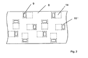
- FIG. 2 shows a top view of the heating apparatus. It can be clearly seen, that below the drying chamber 5, a multitude of heating devices 18 are located. Here, always five heating devices 18 are arranged in a recurrent pattern. Each of the heating devices 18 is designed as described according to figure 1 , whereas one individual energy supply, which each located removed from the inventive apparatus, provides the power to one microwave source 14.
- the cooling circuit comprises preferably one branch per heating device 18, whereas the branches are operated in parallel. All branches are connected to one heat sink 7.
Landscapes
- Chemical & Material Sciences (AREA)
- Life Sciences & Earth Sciences (AREA)
- Biochemistry (AREA)
- Organic Chemistry (AREA)
- Drying Of Solid Materials (AREA)
Description
- The present invention relates to a sugar cube production- and drying apparatus comprising:
- a press for shaping a sugar mass in sugar cubes,
- a heating apparatus for heating and dehumidifying the sugar cubes,
- a conditioning apparatus for cooling and dehumidifying the sugar cubes and
- transportation means for transporting the sugar cubes from the press to the heating apparatus and from there to the conditioning apparatus,
- Such an apparatus is for example known from
EP0894871 B1 . The apparatus described in this patent has however the deficiency, that the amount of sugar cubes which are produced per time unit, has to be relatively constant. - It was therefore the objective of the present invention to provide a sugar cube production-and drying apparatus which does not comprise the deficiencies according to the state of the art.
- This problem is attained by a sugar cube production- and drying apparatus comprising:
- a press for shaping a sugar mass in sugar cubes,
- a heating apparatus for heating and dehumidifying the sugar cubes,
- a conditioning apparatus for cooling and dehumidifying the sugar cubes,
- transportation means for transporting the sugar cubes from the press to the heating apparatus and from there to the conditioning apparatus,
- The present invention relates to a sugar cube production- and drying apparatus. In this apparatus, sugar particles are mixed with water and this sugar mass is then formed in a press in sugar cubes. These sugar cubes are subsequently discharged on a transportation means, for example a transportation belt, which transports the sugar cubes to a heating apparatus for heating the sugar cubes in a drying chamber, in order to evaporated the water content of the sugar cubes at least partially. The water vapor is removed from the drying chamber, for example, by ventilation of the drying chamber. Downstream from the heating apparatus a conditioning apparatus is positioned for cooling and dehumidifying the sugar cubes. Finally, the sugar cubes are packaged for example in boxes.
- The heating apparatus according to the present invention comprises a multitude of heating devices, whereas each heating device has a microwave source, a magnetron, which emits microwave radiation. In a wave guide preferably a rectangular wave guide, the microwave radiation is guided from the microwave source to the drying chamber in which the sugar cubes are heated and consequently, in which the water content of the sugar cubes vaporizes at least partially. The water vapor is intermittently or continuously removed from the drying chamber.
- In most cases, the microwave radiation is not absorbed entirely by the water molecules in the sugar cubes, but reflected, at least partially, back into the wave guide. The amount reflected depends on the amount of radiation and the amount of water introduced into the drying chamber per time unit.
- According to the present invention, the inventive apparatus comprises an isolator in the wave guide that allows the transmission of the radiation only in the direction from the source to the drying chamber. Thus, back radiation will not be guided beyond this isolator in the wave guide. Consequently, even if the load of sugar cubes to be dried and thus the back radiation alters, this does not influence the inventive apparatus, which is consequently much more flexible than the apparatus according to the state of the art. Furthermore the lifetime of the microwave source can be increased.
- Preferably, the isolator is connected to a water cooling, preferably a water cooling circuit, whereas the isolator redirects back radiation reflected from the drying chamber into the water cooling, preferably the water cooling circuit, where the back radiation is absorbed by the water. More preferably, the inventive apparatus comprises a heat sink in the water cooling circuit, where the heat, transferred to the water circuit, is removed and the water is then circulated to the isolator. The heat that is removed from the water circuit in the heat sink is preferably reused for example in the inventive process to heat air that flows, for example, through the drying chamber. Additionally or alternatively, the heat can be used in a different process and/or in order to heat for example a building or to drive a generator.
- In another preferred embodiment, the cooling circuit also cools the microwave source, whereas the microwave source is located in the cooling circuit, preferably upstream from the isolator.
- Preferably, the inventive apparatus comprises in the wave guide, preferably between the isolator and the drying chamber, means to neutralize the back radiation at least partially, so that the back radiation load, which has to be absorbed in the isolator is reduced. In a preferred embodiment, the neutralization of the back radiation is achieved by modulating the oscillation of the back radiation, so that the generated radiation at least partially neutralizes the energy of the back radiation.
- In a preferred embodiment the inventive apparatus comprises measurement means to measure the amount of back radiation. This signal is preferably used to adjust the neutralization means.
- Preferably the means to neutralize the back radiation is a multitude, preferably three metal rods, which extend into the wave guide, whereas their extension into the wave guide is adjustable. By adjusting the extension of the rods into the wave guide, the wave's length and/or preferably the phase of the back radiation can be altered.
- According to a preferred or to another inventive embodiment of the present invention the inventive apparatus comprises one energy supply for each microwave source, whereas the power supplies are located separate from the inventive apparatus. This embodiment of the present invention has the advantage, that the microwave sources and/or the wave guides are accessible more easily and that an additional heat source, the power supply, is removed from the microwave sources, which increases the lifetime of the microwave sources.
- The present invention is now explained according to
figures 1 and2 . -
Figure 1 shows a side view of the inventive apparatus. -
Figure 2 shows a top view of the inventive apparatus. -
Figure 1 shows theheating apparatus 17, which is part of the inventive apparatus 1 to produce sugar cubes. In this apparatus 1, sugar and water are supplied in the usual way to a press, in which the sugar and the water are mixed and in which the sugar cubes are pressed into the correct shape, size and weight. From the press the sugar cubes are conveyed by transportation means 2 to theheating apparatus 17. Theheating apparatus 17 contains a multimode heating devices 18 (comparefigure 2 ). The conveyingapparatus 2 conveys the wet sugar cubes 4 through a drying chamber, where the sugar cubes 4 are heated by microwave energy to a temperature of approximately 75 °C and most of the humidity in the sugar cubes 4 is evaporated. Thus, the sugar cubes 4 absorb enough latent energy to arrive at the desired final humidity content in a conditioning apparatus. After the sugar cubes have been conveyed through the conditioning apparatus 4, they are conveyed to a usual packaging apparatus by the transportation means 2, where the sugar cubes are packed in boxes or the like. The press, the transportation means 2 and the packaging apparatus are electrically driven in the known manner, the drives being adapted to one another. In order to lose as little microwave energy as possible, the transportation means 2 is preferably a conveyor belt made of synthetic material, the dielectric characteristics of which being such, that the conveyor belt takes up as little energy as possible. - The
heating apparatus 17 of the inventive apparatus 1 comprises a multitude of heating devices 18 (comparefigure 2 ), whereas only one heating device is depicted infigure 1 . Theheating device 18 comprises awave guide 10 which is connected to asupport 6, here a stainless steel plate, which is, for example, part of the frame of the apparatus 1, by, for example, aflange 8. Thesupport 6 comprises anopening 9 through which themicrowave radiation 19 can be transferred into thedrying chamber 5. At the bottom of the wave guide amicrowave source 14, a magnetron, is located, which emits microwave radiation into thewave guide 10. Thiswave guide 10 then directs the radiation, as depicted by thearrows 19, in the direction of thedrying chamber 5. Relative to theradiation direction 19, upstream of themicrowave source 14, anisolator 15 is located, which allows only the transmission of microwaves as indicated by thearrows 19.Back radiation 20 cannot get passed this isolator. This isolator is for example a device that transfers theback radiation 20 into awater load 13 where it is absorbed. The isolator, for example, comprises a permanent magnet to redirect theback radiation 20 into thewater load 13. - Further upstream from the
isolator 15 in thewave guide 10 or on the isolator, ameasurement device 16 islocated, which measures the amount ofback radiation 20. The signal of this measurement is preferably used to adjust or control back radiation neutralization means 12, which are also located upstream to the isolator. These back radiation neutralization means 12 are, in the present case, a multitude, here threerods 12, whose extension into thewave guide 10 can be adjusted. By adjusting the extension of these rods, the bandwidth and/or the phase of theback radiation 20 can be altered such, that its energy is neutralized by theradiation 19, while theradiation 19 remains as emitted. - The
inventive heating apparatus 17 further comprises awater cooling circuit 13, which is connected to theisolator 15 to provide a continuous or intermittent water flow, which absorbs the back radiation energy directed from the isolator into thewater cooling circuit 13. Thewater circuit 13 coming from theisolator 15 preferably also cools themicrowave source 14, whereas, preferably, the microwave source is located upstream from the isolator. The heated water is then cooled in aheat sink 7 and the cooled water is then recirculated to the isolator and/or themicrowave source 14. The heat removed from thewater circuit 13 in theheat sink 7 can be utilized by the inventive apparatus for example for heating air ventilated through the dryingchamber 5 and/or to preheat the sugar. Additionally or alternatively the heat can be used to heat a building or to generate electricity. - As can be also seen from
figure 1 , there is oneindividual energy source 11 for eachmicrowave source 14. Furthermore, it can be seen, that thisenergy source 11 is located removed from the inventive apparatus. -
Figure 2 shows a top view of the heating apparatus. It can be clearly seen, that below the dryingchamber 5, a multitude ofheating devices 18 are located. Here, always fiveheating devices 18 are arranged in a recurrent pattern. Each of theheating devices 18 is designed as described according tofigure 1 , whereas one individual energy supply, which each located removed from the inventive apparatus, provides the power to onemicrowave source 14. The cooling circuit comprises preferably one branch perheating device 18, whereas the branches are operated in parallel. All branches are connected to oneheat sink 7. -
- 1
- apparatus to produce sugar cubes
- 2
- transportation means, transportation belt
- 3
- anti friction means
- 4
- sugar cube
- 5
- drying chamber
- 6
- support, stainless steel plate
- 7
- heat sink
- 8
- flange
- 9
- opening in the support
- 10
- wave guide
- 11
- power supply
- 12
- back radiation neutralization means to influence oscillation of the back radiation
- 13
- water cooling, water cooling circuit
- 14
- magnetron, microwave source
- 15
- isolator
- 16
- measurement device, preferably located on the
isolator 15 - 17
- heating apparatus
- 18
- heating device
- 19
- radiation
- 20
- back radiation
Claims (9)
- Sugar cube production- and drying apparatus (1) comprising:- a press for shaping a sugar mass in sugar cubes (4),- a heating apparatus (17) for heating and dehumidifying the sugar cubes (4),- a conditioning apparatus for cooling and dehumidifying the sugar cubes (4)- transportation means (2) for transporting the sugar cubes (4) from the press to the heating apparatus (17) and from there to the conditioning apparatus,whereas the heating apparatus (17) comprises a multitude of heating devices (18), each heating device (18) having a microwave source (14) emitting microwave radiation and a wave guide (10) to guide the microwave radiation (19) from the microwave source (14) to a drying chamber (5) in which the sugar cubes are heated, characterized in, that each heating device (18) comprises an isolator (15) located in the wave guide (10) that allows the transmission of radiation only in the direction from the source (14) to the drying chamber (5).
- Sugar cube production- and drying apparatus (1), according to claim 1, characterized in, that isolator (15) is connected to a water cooling (13), preferably a water cooling circuit, whereas the isolator (15) redirects back radiation (20), reflected from the drying chamber (5), into the water cooling (13), preferably the water cooling circuit (13), where the back radiation is absorbed.
- Sugar cube production- and drying apparatus (1) according to claim 2, characterized in, that a heat sink (7) is part of the water cooling circuit (13).
- Sugar cube production- and drying apparatus (1) according to claim 3, characterized in, that the heat that is recovered in the heat sink (7) is reused.
- Sugar cube production- and drying apparatus (1) according to one of claims 2 - 4, characterized in, that the water cooling circuit (13) cools the microwave source (14).
- Sugar cube production- and drying apparatus (1) according to one of the preceding claims, characterized in, that it comprises in the wave guide (10) downstream from the isolator (15) means (12) to neutralize the back radiation (20) at least partially, preferably by modulating the oscillation of the back radiation (20).
- Sugar cube production- and drying apparatus (1) according to claim 6, characterized in, that it comprises measurement means (16) to measure the back radiation (20) and that means (12) are adjusted based on a signal from the measurement means (16).
- Sugar cube production- and drying apparatus (1) according to claims 6 or 7, characterized in, that the means (12) is a multitude of metal rods which extend into the wave guide (10), whereas their extension into the wave guide (10) is adjustable.
- Sugar cube production- and drying apparatus (1), preferably according to one of the preceding claims, characterized in, that it comprises multiple central power supplies (11), which is separated from the sugar cube production- and drying apparatus (1).
Priority Applications (2)
| Application Number | Priority Date | Filing Date | Title |
|---|---|---|---|
| EP20110000703 EP2481820B1 (en) | 2011-01-28 | 2011-01-28 | Apparatus for drying sugar cubes with microwave radiation |
| RU2012103037/13A RU2587569C2 (en) | 2011-01-28 | 2012-01-30 | Apparatus for drying sugar cubes with microwave radiation |
Applications Claiming Priority (1)
| Application Number | Priority Date | Filing Date | Title |
|---|---|---|---|
| EP20110000703 EP2481820B1 (en) | 2011-01-28 | 2011-01-28 | Apparatus for drying sugar cubes with microwave radiation |
Publications (2)
| Publication Number | Publication Date |
|---|---|
| EP2481820A1 EP2481820A1 (en) | 2012-08-01 |
| EP2481820B1 true EP2481820B1 (en) | 2013-10-16 |
Family
ID=44209630
Family Applications (1)
| Application Number | Title | Priority Date | Filing Date |
|---|---|---|---|
| EP20110000703 Not-in-force EP2481820B1 (en) | 2011-01-28 | 2011-01-28 | Apparatus for drying sugar cubes with microwave radiation |
Country Status (2)
| Country | Link |
|---|---|
| EP (1) | EP2481820B1 (en) |
| RU (1) | RU2587569C2 (en) |
Family Cites Families (5)
| Publication number | Priority date | Publication date | Assignee | Title |
|---|---|---|---|---|
| DE924860C (en) * | 1952-12-31 | 1955-03-07 | Rudolf Carl Bremer | Method and device for drying sugar in body form by means of high frequency |
| FR1432082A (en) * | 1964-04-18 | 1966-03-18 | Buckau Wolf Maschf R | Process for drying sugar lumps |
| US4294624A (en) * | 1980-03-14 | 1981-10-13 | Veltman Preston Leonard | Drying co-mingled carbohydrate solution and recycled product by dielectric heating |
| NL8001629A (en) * | 1980-03-19 | 1981-10-16 | Stork Bepak Bv | METHOD AND APPARATUS FOR TRANSPORTING BLOCKS FROM A FORMING MACHINE FOR CONDITIONING |
| NL1006216C2 (en) | 1997-06-03 | 1998-12-04 | Aquarius Bv | Device for drying sugar cubes. |
-
2011
- 2011-01-28 EP EP20110000703 patent/EP2481820B1/en not_active Not-in-force
-
2012
- 2012-01-30 RU RU2012103037/13A patent/RU2587569C2/en not_active IP Right Cessation
Also Published As
| Publication number | Publication date |
|---|---|
| RU2012103037A (en) | 2013-08-10 |
| EP2481820A1 (en) | 2012-08-01 |
| RU2587569C2 (en) | 2016-06-20 |
Similar Documents
| Publication | Publication Date | Title |
|---|---|---|
| KR100507447B1 (en) | Dehydration Plant and Method of Operating the Same | |
| CA2888921C (en) | Apparatus and method for dehydration using microwave radiation | |
| JP3844306B2 (en) | Equipment for heat-treating screw conveyor bulk material | |
| US3277580A (en) | Method and apparatus for drying | |
| US9073253B2 (en) | Apparatus and method for heating containers | |
| US11435141B2 (en) | Radiant conveyor drying system and method | |
| JPH1089846A (en) | Drying and / or crystallization equipment | |
| US20140298851A1 (en) | Combined Impingement/Plate Freezer | |
| CN102160585B (en) | Multi-layered tunnel type tea infrared fragrance extracting machine | |
| US20080104857A1 (en) | Multistage Continuous Microwave Dryer For Plate-Shaped Products, Especially Fiber Boards | |
| KR100755384B1 (en) | Continuous Agriculture & Livestock Drying System | |
| EP2481820A1 (en) | Apparatus for drying sugar cubes with microwave radiation | |
| JP4658995B2 (en) | Microwave continuous heating device | |
| US3027442A (en) | High-frequency furnaces | |
| RU2556899C1 (en) | Device for heat treatment of grain | |
| KR950012436B1 (en) | Continuous Microwave Sterilizer for Food | |
| EP0512259A2 (en) | Method for pasteurizing food products and pasteurizing machine suited to realize said method | |
| RU2171079C2 (en) | Drying method (versions) | |
| NO309210B1 (en) | Appliance for heating and drying | |
| RU2650011C1 (en) | Conveyor dryer | |
| JP2009100675A (en) | Continuous and uniform heating equipment for food by circular polarization | |
| EP0894871B1 (en) | Apparatus for drying sugar cubes | |
| RU2479954C1 (en) | Plant for microwave treatment of loose products or materials | |
| SU1752331A1 (en) | Plant for shf energy drying of carrot | |
| RU2854007C1 (en) | Installation for mw processing of dielectric materials |
Legal Events
| Date | Code | Title | Description |
|---|---|---|---|
| PUAI | Public reference made under article 153(3) epc to a published international application that has entered the european phase |
Free format text: ORIGINAL CODE: 0009012 |
|
| AK | Designated contracting states |
Kind code of ref document: A1 Designated state(s): AL AT BE BG CH CY CZ DE DK EE ES FI FR GB GR HR HU IE IS IT LI LT LU LV MC MK MT NL NO PL PT RO RS SE SI SK SM TR |
|
| AX | Request for extension of the european patent |
Extension state: BA ME |
|
| 17P | Request for examination filed |
Effective date: 20130130 |
|
| GRAP | Despatch of communication of intention to grant a patent |
Free format text: ORIGINAL CODE: EPIDOSNIGR1 |
|
| INTG | Intention to grant announced |
Effective date: 20130326 |
|
| GRAS | Grant fee paid |
Free format text: ORIGINAL CODE: EPIDOSNIGR3 |
|
| GRAA | (expected) grant |
Free format text: ORIGINAL CODE: 0009210 |
|
| AK | Designated contracting states |
Kind code of ref document: B1 Designated state(s): AL AT BE BG CH CY CZ DE DK EE ES FI FR GB GR HR HU IE IS IT LI LT LU LV MC MK MT NL NO PL PT RO RS SE SI SK SM TR |
|
| REG | Reference to a national code |
Ref country code: GB Ref legal event code: FG4D |
|
| REG | Reference to a national code |
Ref country code: CH Ref legal event code: EP |
|
| REG | Reference to a national code |
Ref country code: IE Ref legal event code: FG4D |
|
| REG | Reference to a national code |
Ref country code: AT Ref legal event code: REF Ref document number: 636566 Country of ref document: AT Kind code of ref document: T Effective date: 20131115 |
|
| REG | Reference to a national code |
Ref country code: DE Ref legal event code: R096 Ref document number: 602011003347 Country of ref document: DE Effective date: 20131212 |
|
| REG | Reference to a national code |
Ref country code: NL Ref legal event code: T3 |
|
| REG | Reference to a national code |
Ref country code: AT Ref legal event code: MK05 Ref document number: 636566 Country of ref document: AT Kind code of ref document: T Effective date: 20131016 |
|
| REG | Reference to a national code |
Ref country code: LT Ref legal event code: MG4D |
|
| PG25 | Lapsed in a contracting state [announced via postgrant information from national office to epo] |
Ref country code: IS Free format text: LAPSE BECAUSE OF FAILURE TO SUBMIT A TRANSLATION OF THE DESCRIPTION OR TO PAY THE FEE WITHIN THE PRESCRIBED TIME-LIMIT Effective date: 20140216 Ref country code: HR Free format text: LAPSE BECAUSE OF FAILURE TO SUBMIT A TRANSLATION OF THE DESCRIPTION OR TO PAY THE FEE WITHIN THE PRESCRIBED TIME-LIMIT Effective date: 20131016 Ref country code: NO Free format text: LAPSE BECAUSE OF FAILURE TO SUBMIT A TRANSLATION OF THE DESCRIPTION OR TO PAY THE FEE WITHIN THE PRESCRIBED TIME-LIMIT Effective date: 20140116 Ref country code: LT Free format text: LAPSE BECAUSE OF FAILURE TO SUBMIT A TRANSLATION OF THE DESCRIPTION OR TO PAY THE FEE WITHIN THE PRESCRIBED TIME-LIMIT Effective date: 20131016 Ref country code: SE Free format text: LAPSE BECAUSE OF FAILURE TO SUBMIT A TRANSLATION OF THE DESCRIPTION OR TO PAY THE FEE WITHIN THE PRESCRIBED TIME-LIMIT Effective date: 20131016 Ref country code: FI Free format text: LAPSE BECAUSE OF FAILURE TO SUBMIT A TRANSLATION OF THE DESCRIPTION OR TO PAY THE FEE WITHIN THE PRESCRIBED TIME-LIMIT Effective date: 20131016 |
|
| PG25 | Lapsed in a contracting state [announced via postgrant information from national office to epo] |
Ref country code: AT Free format text: LAPSE BECAUSE OF FAILURE TO SUBMIT A TRANSLATION OF THE DESCRIPTION OR TO PAY THE FEE WITHIN THE PRESCRIBED TIME-LIMIT Effective date: 20131016 Ref country code: LV Free format text: LAPSE BECAUSE OF FAILURE TO SUBMIT A TRANSLATION OF THE DESCRIPTION OR TO PAY THE FEE WITHIN THE PRESCRIBED TIME-LIMIT Effective date: 20131016 Ref country code: RS Free format text: LAPSE BECAUSE OF FAILURE TO SUBMIT A TRANSLATION OF THE DESCRIPTION OR TO PAY THE FEE WITHIN THE PRESCRIBED TIME-LIMIT Effective date: 20131016 Ref country code: CY Free format text: LAPSE BECAUSE OF FAILURE TO SUBMIT A TRANSLATION OF THE DESCRIPTION OR TO PAY THE FEE WITHIN THE PRESCRIBED TIME-LIMIT Effective date: 20131016 Ref country code: ES Free format text: LAPSE BECAUSE OF FAILURE TO SUBMIT A TRANSLATION OF THE DESCRIPTION OR TO PAY THE FEE WITHIN THE PRESCRIBED TIME-LIMIT Effective date: 20131016 |
|
| PG25 | Lapsed in a contracting state [announced via postgrant information from national office to epo] |
Ref country code: PT Free format text: LAPSE BECAUSE OF FAILURE TO SUBMIT A TRANSLATION OF THE DESCRIPTION OR TO PAY THE FEE WITHIN THE PRESCRIBED TIME-LIMIT Effective date: 20140217 |
|
| REG | Reference to a national code |
Ref country code: DE Ref legal event code: R097 Ref document number: 602011003347 Country of ref document: DE |
|
| PG25 | Lapsed in a contracting state [announced via postgrant information from national office to epo] |
Ref country code: EE Free format text: LAPSE BECAUSE OF FAILURE TO SUBMIT A TRANSLATION OF THE DESCRIPTION OR TO PAY THE FEE WITHIN THE PRESCRIBED TIME-LIMIT Effective date: 20131016 |
|
| PLBE | No opposition filed within time limit |
Free format text: ORIGINAL CODE: 0009261 |
|
| STAA | Information on the status of an ep patent application or granted ep patent |
Free format text: STATUS: NO OPPOSITION FILED WITHIN TIME LIMIT |
|
| PG25 | Lapsed in a contracting state [announced via postgrant information from national office to epo] |
Ref country code: LU Free format text: LAPSE BECAUSE OF FAILURE TO SUBMIT A TRANSLATION OF THE DESCRIPTION OR TO PAY THE FEE WITHIN THE PRESCRIBED TIME-LIMIT Effective date: 20140128 Ref country code: PL Free format text: LAPSE BECAUSE OF FAILURE TO SUBMIT A TRANSLATION OF THE DESCRIPTION OR TO PAY THE FEE WITHIN THE PRESCRIBED TIME-LIMIT Effective date: 20131016 Ref country code: IT Free format text: LAPSE BECAUSE OF FAILURE TO SUBMIT A TRANSLATION OF THE DESCRIPTION OR TO PAY THE FEE WITHIN THE PRESCRIBED TIME-LIMIT Effective date: 20131016 Ref country code: SK Free format text: LAPSE BECAUSE OF FAILURE TO SUBMIT A TRANSLATION OF THE DESCRIPTION OR TO PAY THE FEE WITHIN THE PRESCRIBED TIME-LIMIT Effective date: 20131016 Ref country code: RO Free format text: LAPSE BECAUSE OF FAILURE TO SUBMIT A TRANSLATION OF THE DESCRIPTION OR TO PAY THE FEE WITHIN THE PRESCRIBED TIME-LIMIT Effective date: 20131016 |
|
| REG | Reference to a national code |
Ref country code: CH Ref legal event code: PL |
|
| 26N | No opposition filed |
Effective date: 20140717 |
|
| PG25 | Lapsed in a contracting state [announced via postgrant information from national office to epo] |
Ref country code: DK Free format text: LAPSE BECAUSE OF FAILURE TO SUBMIT A TRANSLATION OF THE DESCRIPTION OR TO PAY THE FEE WITHIN THE PRESCRIBED TIME-LIMIT Effective date: 20131016 |
|
| REG | Reference to a national code |
Ref country code: DE Ref legal event code: R097 Ref document number: 602011003347 Country of ref document: DE Effective date: 20140717 |
|
| PG25 | Lapsed in a contracting state [announced via postgrant information from national office to epo] |
Ref country code: LI Free format text: LAPSE BECAUSE OF NON-PAYMENT OF DUE FEES Effective date: 20140131 Ref country code: CH Free format text: LAPSE BECAUSE OF NON-PAYMENT OF DUE FEES Effective date: 20140131 |
|
| REG | Reference to a national code |
Ref country code: IE Ref legal event code: MM4A |
|
| PG25 | Lapsed in a contracting state [announced via postgrant information from national office to epo] |
Ref country code: IE Free format text: LAPSE BECAUSE OF NON-PAYMENT OF DUE FEES Effective date: 20140128 |
|
| PG25 | Lapsed in a contracting state [announced via postgrant information from national office to epo] |
Ref country code: SI Free format text: LAPSE BECAUSE OF FAILURE TO SUBMIT A TRANSLATION OF THE DESCRIPTION OR TO PAY THE FEE WITHIN THE PRESCRIBED TIME-LIMIT Effective date: 20131016 |
|
| PG25 | Lapsed in a contracting state [announced via postgrant information from national office to epo] |
Ref country code: MC Free format text: LAPSE BECAUSE OF FAILURE TO SUBMIT A TRANSLATION OF THE DESCRIPTION OR TO PAY THE FEE WITHIN THE PRESCRIBED TIME-LIMIT Effective date: 20131016 |
|
| GBPC | Gb: european patent ceased through non-payment of renewal fee |
Effective date: 20150128 |
|
| PG25 | Lapsed in a contracting state [announced via postgrant information from national office to epo] |
Ref country code: GB Free format text: LAPSE BECAUSE OF NON-PAYMENT OF DUE FEES Effective date: 20150128 |
|
| REG | Reference to a national code |
Ref country code: FR Ref legal event code: PLFP Year of fee payment: 6 |
|
| PG25 | Lapsed in a contracting state [announced via postgrant information from national office to epo] |
Ref country code: MT Free format text: LAPSE BECAUSE OF FAILURE TO SUBMIT A TRANSLATION OF THE DESCRIPTION OR TO PAY THE FEE WITHIN THE PRESCRIBED TIME-LIMIT Effective date: 20131016 |
|
| PG25 | Lapsed in a contracting state [announced via postgrant information from national office to epo] |
Ref country code: SM Free format text: LAPSE BECAUSE OF FAILURE TO SUBMIT A TRANSLATION OF THE DESCRIPTION OR TO PAY THE FEE WITHIN THE PRESCRIBED TIME-LIMIT Effective date: 20131016 |
|
| PG25 | Lapsed in a contracting state [announced via postgrant information from national office to epo] |
Ref country code: GR Free format text: LAPSE BECAUSE OF FAILURE TO SUBMIT A TRANSLATION OF THE DESCRIPTION OR TO PAY THE FEE WITHIN THE PRESCRIBED TIME-LIMIT Effective date: 20140117 Ref country code: BG Free format text: LAPSE BECAUSE OF FAILURE TO SUBMIT A TRANSLATION OF THE DESCRIPTION OR TO PAY THE FEE WITHIN THE PRESCRIBED TIME-LIMIT Effective date: 20131016 |
|
| PG25 | Lapsed in a contracting state [announced via postgrant information from national office to epo] |
Ref country code: HU Free format text: LAPSE BECAUSE OF FAILURE TO SUBMIT A TRANSLATION OF THE DESCRIPTION OR TO PAY THE FEE WITHIN THE PRESCRIBED TIME-LIMIT; INVALID AB INITIO Effective date: 20110128 |
|
| REG | Reference to a national code |
Ref country code: FR Ref legal event code: PLFP Year of fee payment: 7 |
|
| REG | Reference to a national code |
Ref country code: FR Ref legal event code: PLFP Year of fee payment: 8 |
|
| PG25 | Lapsed in a contracting state [announced via postgrant information from national office to epo] |
Ref country code: MK Free format text: LAPSE BECAUSE OF FAILURE TO SUBMIT A TRANSLATION OF THE DESCRIPTION OR TO PAY THE FEE WITHIN THE PRESCRIBED TIME-LIMIT Effective date: 20131016 |
|
| PG25 | Lapsed in a contracting state [announced via postgrant information from national office to epo] |
Ref country code: AL Free format text: LAPSE BECAUSE OF FAILURE TO SUBMIT A TRANSLATION OF THE DESCRIPTION OR TO PAY THE FEE WITHIN THE PRESCRIBED TIME-LIMIT Effective date: 20131016 |
|
| PGFP | Annual fee paid to national office [announced via postgrant information from national office to epo] |
Ref country code: NL Payment date: 20200122 Year of fee payment: 10 Ref country code: DE Payment date: 20200123 Year of fee payment: 10 |
|
| PGFP | Annual fee paid to national office [announced via postgrant information from national office to epo] |
Ref country code: BE Payment date: 20200122 Year of fee payment: 10 Ref country code: CZ Payment date: 20200116 Year of fee payment: 10 |
|
| PGFP | Annual fee paid to national office [announced via postgrant information from national office to epo] |
Ref country code: FR Payment date: 20200123 Year of fee payment: 10 Ref country code: TR Payment date: 20200124 Year of fee payment: 10 |
|
| REG | Reference to a national code |
Ref country code: DE Ref legal event code: R119 Ref document number: 602011003347 Country of ref document: DE |
|
| REG | Reference to a national code |
Ref country code: NL Ref legal event code: MM Effective date: 20210201 |
|
| REG | Reference to a national code |
Ref country code: BE Ref legal event code: MM Effective date: 20210131 |
|
| PG25 | Lapsed in a contracting state [announced via postgrant information from national office to epo] |
Ref country code: NL Free format text: LAPSE BECAUSE OF NON-PAYMENT OF DUE FEES Effective date: 20210201 Ref country code: FR Free format text: LAPSE BECAUSE OF NON-PAYMENT OF DUE FEES Effective date: 20210131 Ref country code: CZ Free format text: LAPSE BECAUSE OF NON-PAYMENT OF DUE FEES Effective date: 20210128 |
|
| PG25 | Lapsed in a contracting state [announced via postgrant information from national office to epo] |
Ref country code: DE Free format text: LAPSE BECAUSE OF NON-PAYMENT OF DUE FEES Effective date: 20210803 |
|
| PG25 | Lapsed in a contracting state [announced via postgrant information from national office to epo] |
Ref country code: BE Free format text: LAPSE BECAUSE OF NON-PAYMENT OF DUE FEES Effective date: 20210131 |
|
| PG25 | Lapsed in a contracting state [announced via postgrant information from national office to epo] |
Ref country code: TR Free format text: LAPSE BECAUSE OF NON-PAYMENT OF DUE FEES Effective date: 20210128 |