EP2481594A2 - Liquid storage container mounted on liquid ejecting apparatus - Google Patents
Liquid storage container mounted on liquid ejecting apparatus Download PDFInfo
- Publication number
- EP2481594A2 EP2481594A2 EP12152265A EP12152265A EP2481594A2 EP 2481594 A2 EP2481594 A2 EP 2481594A2 EP 12152265 A EP12152265 A EP 12152265A EP 12152265 A EP12152265 A EP 12152265A EP 2481594 A2 EP2481594 A2 EP 2481594A2
- Authority
- EP
- European Patent Office
- Prior art keywords
- chamber
- liquid
- ink
- liquid storage
- storage container
- Prior art date
- Legal status (The legal status is an assumption and is not a legal conclusion. Google has not performed a legal analysis and makes no representation as to the accuracy of the status listed.)
- Withdrawn
Links
- 239000007788 liquid Substances 0.000 title claims abstract description 104
- 230000037361 pathway Effects 0.000 claims abstract description 6
- 230000005484 gravity Effects 0.000 claims description 8
- 238000005192 partition Methods 0.000 claims description 8
- 238000007789 sealing Methods 0.000 description 10
- 239000000758 substrate Substances 0.000 description 9
- 238000004519 manufacturing process Methods 0.000 description 3
- 238000000926 separation method Methods 0.000 description 3
- 238000011144 upstream manufacturing Methods 0.000 description 3
- 230000003247 decreasing effect Effects 0.000 description 2
- 238000005516 engineering process Methods 0.000 description 1
- 230000006870 function Effects 0.000 description 1
- 239000000463 material Substances 0.000 description 1
- 239000012528 membrane Substances 0.000 description 1
- 239000011347 resin Substances 0.000 description 1
- 229920005989 resin Polymers 0.000 description 1
Images



Classifications
-
- B—PERFORMING OPERATIONS; TRANSPORTING
- B41—PRINTING; LINING MACHINES; TYPEWRITERS; STAMPS
- B41J—TYPEWRITERS; SELECTIVE PRINTING MECHANISMS, i.e. MECHANISMS PRINTING OTHERWISE THAN FROM A FORME; CORRECTION OF TYPOGRAPHICAL ERRORS
- B41J2/00—Typewriters or selective printing mechanisms characterised by the printing or marking process for which they are designed
- B41J2/005—Typewriters or selective printing mechanisms characterised by the printing or marking process for which they are designed characterised by bringing liquid or particles selectively into contact with a printing material
- B41J2/01—Ink jet
- B41J2/17—Ink jet characterised by ink handling
- B41J2/175—Ink supply systems ; Circuit parts therefor
- B41J2/17503—Ink cartridges
- B41J2/17556—Means for regulating the pressure in the cartridge
-
- B—PERFORMING OPERATIONS; TRANSPORTING
- B41—PRINTING; LINING MACHINES; TYPEWRITERS; STAMPS
- B41J—TYPEWRITERS; SELECTIVE PRINTING MECHANISMS, i.e. MECHANISMS PRINTING OTHERWISE THAN FROM A FORME; CORRECTION OF TYPOGRAPHICAL ERRORS
- B41J2/00—Typewriters or selective printing mechanisms characterised by the printing or marking process for which they are designed
- B41J2/005—Typewriters or selective printing mechanisms characterised by the printing or marking process for which they are designed characterised by bringing liquid or particles selectively into contact with a printing material
- B41J2/01—Ink jet
- B41J2/17—Ink jet characterised by ink handling
- B41J2/175—Ink supply systems ; Circuit parts therefor
- B41J2/17503—Ink cartridges
- B41J2/17513—Inner structure
-
- B—PERFORMING OPERATIONS; TRANSPORTING
- B41—PRINTING; LINING MACHINES; TYPEWRITERS; STAMPS
- B41J—TYPEWRITERS; SELECTIVE PRINTING MECHANISMS, i.e. MECHANISMS PRINTING OTHERWISE THAN FROM A FORME; CORRECTION OF TYPOGRAPHICAL ERRORS
- B41J2/00—Typewriters or selective printing mechanisms characterised by the printing or marking process for which they are designed
- B41J2/005—Typewriters or selective printing mechanisms characterised by the printing or marking process for which they are designed characterised by bringing liquid or particles selectively into contact with a printing material
- B41J2/01—Ink jet
- B41J2/17—Ink jet characterised by ink handling
- B41J2/175—Ink supply systems ; Circuit parts therefor
- B41J2/17566—Ink level or ink residue control
Definitions
- the present invention relates to a liquid storage container which is applied to a liquid ejecting apparatus ejecting a liquid such as ink and stores the liquid therein.
- a printing apparatus which prints an image by ejecting ink onto a printing medium is widely used.
- the image is printed by ejecting the ink from an ejecting head while reciprocating a carriage on which the ejecting head is provided on the printing medium.
- the ejected ink is stored in an exclusive storage container referred to as an ink cartridge and mounted on the carriage.
- the ink cartridge may include predetermined devices.
- the predetermined devices there is a residual quantity sensor for detecting the residual ink quantity of the ink cartridge.
- the residual quantity sensor is disposed in a chamber referred to as a sensor chamber in which the periphery is surrounded by walls.
- the sensor chamber is configured so as to be filled with ink while the ink remains in the ink cartridge. Accordingly, the residual quantity sensor detects whether or not the sensor chamber is filled with the ink, and therefore, the residual quantity sensor detects the residual ink quantity in the ink cartridge.
- a circuit substrate is provided in the vicinity of a device chamber into which devices such as a sensor are accommodated, and the devices are electrically connected to the circuit substrate.
- the ink cartridge is mounted on the printing apparatus, and therefore, the devices such as the residual quantity sensor are electrically connected to the printing apparatus via the circuit substrate.
- a memory for storing various information such as the ink type or the date of manufacture, and the like are also mounted on the circuit substrate.
- the ink cartridge described in JP-A-2009-285889 is known.
- the sensor chamber is separated from the walls and adjacent to a bubble separation chamber.
- the sensor chamber and the bubble separation chamber are filled with ink in a state where the ink is stored in the ink cartridge.
- impact due to the ink in the adjacent bubble separation chambers is transmitted to the sensor chamber via the walls when the ink cartridge collides with a floor. Therefore, there is a concern that damage may be applied to the residual quantity sensor installed in the sensor chamber or the memory provided in the vicinity of the sensor chamber, or the like.
- the above-described problem is similarly generated in a cartridge which includes devices other than the sensor.
- An advantage of some aspects of the invention is to provide a technology capable of avoiding damage to a device such as a residual quantity sensor even when impact is applied to a liquid storage container such as dropping of the liquid storage container.
- a liquid storage container which is mounted on a liquid ejecting apparatus ejecting a liquid from an ejecting head and supplies the liquid to the ejecting head including a liquid storage chamber that stores the liquid therein, a liquid supply portion that supplies the liquid to the ejecting head, a device chamber that is provided in a pathway supplying the liquid from the liquid storage chamber to the liquid supply portion and includes a device in the inner portion thereof, and an air chamber that is provided in a pathway supplying air from the outside to the liquid storage chamber according to a decrease of the liquid in the liquid storage chamber, is filled with air in the inner portion, and prevents the liquid from being leaked to the outside by trapping the liquid when the liquid flows backward from the liquid storage chamber, wherein among walls which surround the device chamber, at least one wall is adjacent to the air chamber.
- the liquid storage container of the aspect of the invention among walls which surround the device chamber, at least one wall is adjacent to the air chamber.
- a wall other than walls which partition the device chamber from the outside may be adjacent to the air chamber.
- the device may be a sensor. In this way, since the device is a sensor, it is also possible to detect a residual quantity of the stored liquid.
- At least one wall may be adjacent to another device. According to the configuration, even when the liquid storage container is dropped and impact is applied to the liquid storage container, as described above, since the impact is not applied to the device chamber from the air chamber, it is difficult for the impact to be applied to the other device which is separated from the walls and adjacent to the device chamber. Thereby, damage to the other device can be also avoided.
- the other device may be a memory.
- the other device is the memory, it is possible to store information such as the kind of the stored liquid and the date of manufacture.
- the center of gravity of the liquid storage container exists in the liquid storage chamber when the liquid storage chamber stores the liquid, and a portion in which the liquid storage chamber exists is larger than a portion in which the air chamber exists in a circumference of the center of gravity.
- a fixing lever that fixes the liquid storage container to the liquid ejecting apparatus may be provided at a side wall close to the device chamber.
- the fixing lever is disposed so as to be close to the device chamber adjacent to the air chamber, the impact applied to the fixing lever can be decreased when the liquid storage container collides with a floor.
- Fig. 1 is an explanatory view exemplifying a state where an ink cartridge is mounted on a carriage of an ink jet printer in a first embodiment of the invention.
- Figs. 2A and 2B are perspective views showing an appearance configuration of the ink cartridge which is mounted on the carriage.
- Fig. 3 is a plan view showing an inner structure of the ink cartridge by peeling a sealing film which is stuck to a rear side of a cartridge main body.
- Fig. 4 is a plan view showing the inner structure of the ink cartridge by peeling a display label which is stuck to a front side of the cartridge main body.
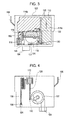
- Figs. 5A to 5D are structure views showing a simplified inner structure of the ink cartridge.
- Figs. 6A to 6D are structure views showing a simplified inner structure of the ink cartridge in a second embodiment of the invention.
- Fig. 1 is an explanatory view exemplifying a state where an ink cartridge 100 is mounted on a carriage 10 of an ink jet printer 1 in a first embodiment of the invention.
- the carriage 10 which reciprocates on a printing medium 2 is provided on the ink jet printer 1, and the ink cartridge 100 is mounted on the carriage 10.
- An ejecting head 20 which ejects the ink is provided in a lower surface side (side facing the printing medium 2) of the carriage 10 for each ink cartridge 100, and the ink stored in the ink cartridge 100 is supplied to the ejecting head 20 and ejected from the ejecting head 20 toward the printing medium 2.
- the illustrated ink jet printer 1 prints an image by using cyan ink (C ink), magenta ink (M ink), yellow ink (Y ink), and black ink (K ink).
- C ink cyan ink
- M ink magenta ink
- Y ink yellow ink
- K ink black ink
- four ink cartridges 100 of the ink cartridge 100 which stores the C ink, the ink cartridge 100 which stores the M ink, the ink cartridge 100 which stores the Y ink, and the ink cartridge 100 which stores the K ink are mounted on the carriage 10.
- Figs. 2A and 2B are perspective views showing an appearance configuration of the ink cartridge 100 which is mounted on the carriage 10 in Fig. 1 .
- the ink cartridge 100 is mainly configured by a cartridge main body 102 having an approximately rectangular shape.
- the cartridge main body 102 is formed of a hard resin material.
- a display label 160 is stuck so as to be bent from the front side surface to the upper surface.
- a sealing film 170 is stuck to the rear side surface of the cartridge main body 102.
- the rear side surface of the cartridge main body 102 is opened, and the ink can be stored in the ink cartridge 100 for the first time by sticking the sealing film 170 on the opening and sealing the ink.
- an ink supply portion 104 for supplying the ink toward the ejecting head 20 of the carriage 10 is provided on the bottom surface of the cartridge main body 102.
- a fixing lever 106 for fixing the ink cartridge 100 to the carriage 10 when mounting the ink cartridge 100 on the carriage 10 is provided in one side surface of the sides of the cartridge main body 102.
- Fig. 3 is a plan view showing the inner structure of the ink cartridge 100 in Figs. 2A and 2B by peeling the sealing film 170 which is stuck to the rear side surface of the cartridge main body 102.
- the sealing film 170 which is stuck to the rear side of the cartridge main body 102 is peeled, a largely opened concave portion 110 appears.
- the concave portion 110 is mainly divided into five regions by a plurality of walls 120 which are vertically and horizontally provided.
- five chambers are formed between the concave portion 110 and the sealing film 170 by sticking the sealing film 170 onto the rear side of the cartridge main body 102 and sealing the concave portion 110.
- a first ink storage chamber 116a is provided at the right side of Fig. 3
- a second ink storage chamber 116b is provided at the upper left of Fig. 3
- a sensor chamber 118 shown by a fine oblique line is provided at the lower left in Fig. 3 with respect to the second ink storage chamber 116b.
- a residual quantity sensor (not shown) is provided in the sensor chamber 118.
- a buffer chamber 119 is obliquely provided to the upper right of the sensor chamber 118.
- the buffer chamber 119 communicates with a pressure regulation chamber 107 by a small round communicating hole 152.
- a membrane valve, a spring (all not shown), and the like are housed in the pressure regulation chamber 107, and the pressure regulation chamber includes a function which regulates pressure of the ink supplied to the carriage 10.
- first ink storage chamber 116a and the second ink storage chamber 116b are connected to each other by an ink passage 150
- the sensor chamber 118 and the buffer chamber 119 are connected to each other by an ink passage 146. Accordingly, when the ink is ejected from the ejecting head 20, after the ink flows from the communicating hole 152 into the pressure regulation chamber 107 via the second ink storage chamber 119, the sensor chamber 118, and the buffer chamber 116b from the first ink storage chamber 116a, the ink is supplied from the ink supply portion 104 to the ejecting head 20.
- an air chamber 114 is also provided at the lower left in Fig. 3 with respect to the first ink storage chamber 116a.
- a communicating hole 130 is provided at the air chamber 114, and as described hereinafter, the communicating hole is connected to a hole open to the atmosphere via an air passage which is provided at the front side of the cartridge main body 102.
- the air chamber 114 is connected to the above-described first ink storage chamber 116a by an air passage 134.
- the air chamber 114 traps the ink in the inner portion and prevents the ink from moving further upward and being leaked from the ink cartridge 100.
- Fig. 4 is a plan view showing the inner structure of the ink cartridge 100 in Fig. 2A and 2B by peeling the display label 160 which is stuck to the front side of the cartridge main body 102.
- a plurality of grooves appear if the display label 160 attached to the front side of the cartridge main body 102 is peeled.
- the grooves are indicated by oblique lines. Passages are formed between each groove and the display label 160 by sticking the display label 160 onto the front side of the cartridge main body 102 and sealing the grooves.
- the passages include a communicating hole 154 which communicates with a hole open to the atmosphere 124 opened to the bottom surface of the cartridge main body 102, as the starting end; an upstream side elongated air passage 128 which meanders while changing direction several times; a downstream side elongated air passage 156 which has the communicating hole 130 described by Fig. 3 as the termination; and an approximately rectangular air reservoir 112 which is provided between the upstream side air passage 156 and the downstream side air passage 128 and formed in a shallow concave shape, or the like.
- the surface configuration of the pressure regulation chamber 107 is shown in the vicinity (right side in Fig. 4 ) of the communicating hole 130.
- the explanation is performed based on the configuration which simplifies the entire structure and changes a portion of the structure.
- Figs. 5A to 5D are structure views showing a simplified inner structure of the ink cartridge 100 shown in Figs. 3 and 4 .
- Fig. 5A is a top view of the cartridge main body 102 when viewed from the upper side
- Fig. 5B is a rear view of the cartridge main body 102 when viewed from the rear side
- Fig. 5C is a side view of the cartridge main body 102 when viewed from the side
- Fig. 5D is a front view of the cartridge main body 102 when viewed from the front side.
- the hole open to the atmosphere 124 is provided on not the bottom surface of the cartridge main body 102 but the upper surface thereof.
- the air reservoir 112 is provided at the upper left corner in the rear side of the cartridge main body 102.
- the air chamber 114 is provided at the lower portion of the cartridge main body 102 and occupies a large portion of the lower portion.
- the ink storage chamber 116 is configured of a single chamber, provided on the upper portion of the cartridge main body 102, and occupies a large portion of the upper portion.
- the sensor chamber 118 is provided at the lower left side of the cartridge main body 102. Accordingly, among walls which surround the sensor chamber 118, a wall 120a is adjacent to the air chamber 114, and a wall 120b is adjacent to the ink storage chamber 116. The other walls are the walls which partition the sensor chamber from the outside. Among the walls which partition the sensor chamber 118 from the outside, a wall 120c is adjacent to a circuit substrate 122 which is provided in the outer portion of the cartridge main body 102. A residual quantity sensor (not shown) in the sensor chamber 118 is electrically connected to the circuit substrate 122 via the wall 120c. Memory (not shown) for storing various information such as the ink type or the date of manufacture, and the like are mounted on the circuit substrate 122. The circuit substrate 122 is electrically connected to the ink jet printer 1 in a state where the ink cartridge 100 is mounted on the carriage 10.
- the fixing lever 106 is provided at the side surface near to the sensor chamber 118 among the surfaces of the sides of the carriage main body 102.
- the air reservoir 112 communicates with the hole open to the atmosphere 124.
- a communicating hole 126 is provided in the air reservoir 112, and as shown in Fig. 5D , the air reservoir communicates with the front side of the carriage main body 102.
- the communicating hole 126 is connected to the communicating hole 130 via the air passage 128.
- the communicating hole 130 communicates with the air chamber 114 in the rear side of the cartridge main body 102.
- a communicating hole 132 is provided in the air chamber 114 and communicates with the front side of the cartridge main body 102.
- the communicating hole 132 is connected to a communicating hole 136 via the air passage 134.
- the communicating hole 136 communicates with the ink storage chamber 116 which is positioned at the rear side of the cartridge main body 102.
- a communicating hole 138 is provided in the ink storage chamber 116 and communicates with the front side of the cartridge main body 102.
- the communicating hole 138 is connected to a communicating hole 142 via an ink passage 140.
- the communicating hole 142 communicates with the sensor chamber 118 in the rear side of the cartridge main body 102.
- a communicating hole 144 is provided in the sensor chamber 118 in addition to the communicating hole 142 and communicates with the front side of the cartridge main body 102.
- the communicating hole 144 is connected to the communicating hole 148 via an ink passage 146.
- the communicating hole 142 communicates with the ink supply portion 104.
- a buffer chamber 119, the pressure regulation chamber 107, and the like are omitted.
- the ink storage chamber 116 is connected to the air chamber 114 via the air passage 134, and the air chamber 114 is opened to the atmosphere via the communicating hole 130, the air passage 128, the communicating hole 126, the air reservoir 112, and the hole open to the atmosphere 124.
- the air chamber 114 traps the ink in the inner portion. Therefore, the ink is prevented from moving further to the upstream side and being leaked from the ink cartridge 100.
- the sensor chamber 118 which is positioned further downstream from the ink storage chamber 116, is filled with ink in a state where the ink exists in the ink storage chamber 116. Accordingly, the residual quantity sensor (not shown), which is installed in the sensor chamber 118, detects the residual ink quantity in the ink cartridge 100 according to detecting whether or not the sensor chamber 118 is filled with ink. The detected result is transmitted to the ink jet printer 1 via the circuit substrate 122.
- the right wall 120a is adjacent to the air chamber 114 as described above while the upper wall 120b is adjacent to the ink storage chamber 116. That is, the chamber which stores the ink is adjacent to the upside of the sensor chamber 118, but the chamber which is filled with air is adjacent to the right side of the sensor chamber 118.
- the impact due to the stored ink is transmitted to the sensor chamber 118 via the wall 120b from the ink storage chamber 116.
- the inner portion of the air chamber 114 is air, the impact from the air chamber 114 is not applied to the sensor chamber. Therefore, the impact which is applied to the residual quantity sensor, the memory, and the like is absorbed to that extent. As a result, damage to the devices can be avoided.
- the center of gravity of the ink cartridge 100 when considering the center of gravity of the ink cartridge 100, the center of gravity does not exist at the air chamber 114 side which is filled with air, but exists at the ink storage chamber 116 side which stores the ink.
- the volume of the portion in which the ink storage chamber 116 exists is larger than the volume of the portion in which the air chamber 114 exists.
- the fixing lever 106 is provided at the side wall which is close to the sensor chamber 118 adjacent to the air chamber 114. Accordingly, when the ink cartridge 100 collides with a floor, the impact of the collision which is applied to the fixing lever 106 can be decreased.
- Figs. 6A to 6D are structure views showing a simplified inner structure of the ink cartridge in a second embodiment of the invention.
- Fig. 6A is a top view of a cartridge main body 202 when viewed from the upper side
- Fig. 6B is a rear view of the cartridge main body 202 when viewed from the rear side
- Fig. 6C is a side view of the cartridge main body 202 when viewed from the side
- Fig. 6D is a front view of the cartridge main body 202 when viewed from the front side.
- an air reservoir 212 is provided so as to be near to the left side of the upper portion of the cartridge main body 202.
- the air chamber 214 is provided at the left side of the cartridge main body 202 and occupies a large portion of the left side portion.
- An ink storage chamber 216 is provided at the right side of the cartridge main body 202 and occupies a great portion of the right side portion.
- the sensor chamber 218 is provided at the left side of the lower portion of the cartridge main body 202, and as described above, is positioned so as to be adjacent to the air chamber 214 via the walls 220a and 220b. Accordingly, in the second embodiment, the upper portion and the right portion of the sensor chamber 218 is adjacent to the chamber which is filled with air, but is not adjacent to the chamber which stores the ink at all.
Landscapes
- Ink Jet (AREA)
Abstract
Description
- The present invention relates to a liquid storage container which is applied to a liquid ejecting apparatus ejecting a liquid such as ink and stores the liquid therein.
- A printing apparatus which prints an image by ejecting ink onto a printing medium is widely used. In the printing apparatus, the image is printed by ejecting the ink from an ejecting head while reciprocating a carriage on which the ejecting head is provided on the printing medium. Moreover, the ejected ink is stored in an exclusive storage container referred to as an ink cartridge and mounted on the carriage.
- The ink cartridge may include predetermined devices. As an example of the predetermined devices, there is a residual quantity sensor for detecting the residual ink quantity of the ink cartridge. The residual quantity sensor is disposed in a chamber referred to as a sensor chamber in which the periphery is surrounded by walls. The sensor chamber is configured so as to be filled with ink while the ink remains in the ink cartridge. Accordingly, the residual quantity sensor detects whether or not the sensor chamber is filled with the ink, and therefore, the residual quantity sensor detects the residual ink quantity in the ink cartridge.
- In addition, a circuit substrate is provided in the vicinity of a device chamber into which devices such as a sensor are accommodated, and the devices are electrically connected to the circuit substrate. Moreover, the ink cartridge is mounted on the printing apparatus, and therefore, the devices such as the residual quantity sensor are electrically connected to the printing apparatus via the circuit substrate. In addition, a memory for storing various information such as the ink type or the date of manufacture, and the like are also mounted on the circuit substrate. For example, as this kind of ink cartridge, the ink cartridge described in
JP-A-2009-285889 - In the ink cartridge described in
JP-A-2009-285889 - An advantage of some aspects of the invention is to provide a technology capable of avoiding damage to a device such as a residual quantity sensor even when impact is applied to a liquid storage container such as dropping of the liquid storage container.
- According to an aspect of the invention, there is provided a liquid storage container which is mounted on a liquid ejecting apparatus ejecting a liquid from an ejecting head and supplies the liquid to the ejecting head including a liquid storage chamber that stores the liquid therein, a liquid supply portion that supplies the liquid to the ejecting head, a device chamber that is provided in a pathway supplying the liquid from the liquid storage chamber to the liquid supply portion and includes a device in the inner portion thereof, and an air chamber that is provided in a pathway supplying air from the outside to the liquid storage chamber according to a decrease of the liquid in the liquid storage chamber, is filled with air in the inner portion, and prevents the liquid from being leaked to the outside by trapping the liquid when the liquid flows backward from the liquid storage chamber, wherein among walls which surround the device chamber, at least one wall is adjacent to the air chamber.
- In this way, in the liquid storage container of the aspect of the invention, among walls which surround the device chamber, at least one wall is adjacent to the air chamber. Thereby, even when the liquid storage container is dropped and impact is applied to the liquid storage container, since the inner portion of the air chamber is filled with air, the impact is not applied to the device chamber from the air chamber. Therefore, compared to the case where the device chamber comes in contact with the chamber which stores liquid, since the impact applied to the device provided in the device chamber is absorbed, damage to the device can be avoided.
- In the liquid storage container of the aspect of the invention, among the walls which surround the device chamber, a wall other than walls which partition the device chamber from the outside may be adjacent to the air chamber.
- In this way, due to the fact that the wall other than walls which partition the device chamber from the outside is adjacent to the air chamber, since the device chamber is not adjacent to the chamber which stores the ink, even when the liquid storage container is dropped and impact is applied to the liquid storage container, impact due to the liquid is not applied to the device chamber from the adjacent chamber. Thereby, since the impact, which is applied to the device provided in the device chamber, is further absorbed, damage to the device can be further avoided.
- In the liquid storage container of the aspect of the invention, the device may be a sensor. In this way, since the device is a sensor, it is also possible to detect a residual quantity of the stored liquid.
- In the liquid storage container of the aspect of the invention, among walls which partition the device chamber from the outside in the walls which surround the device chamber, at least one wall may be adjacent to another device. According to the configuration, even when the liquid storage container is dropped and impact is applied to the liquid storage container, as described above, since the impact is not applied to the device chamber from the air chamber, it is difficult for the impact to be applied to the other device which is separated from the walls and adjacent to the device chamber. Thereby, damage to the other device can be also avoided.
- In the liquid storage container of the aspect of the invention, the other device may be a memory. In this way, due to the fact that the other device is the memory, it is possible to store information such as the kind of the stored liquid and the date of manufacture.
- In the liquid storage container of the aspect of the invention, the center of gravity of the liquid storage container exists in the liquid storage chamber when the liquid storage chamber stores the liquid, and a portion in which the liquid storage chamber exists is larger than a portion in which the air chamber exists in a circumference of the center of gravity.
- When the liquid storage container is dropped, since it is highly possible that the liquid storage container drops in the state where the air chamber side faces upward if considering the center of gravity of the liquid storage container, it is possible to suppress the air chamber from being directly subjected to the impact at the time of the dropping according to the configuration.
- In the liquid storage container of the aspect of the invention, a fixing lever that fixes the liquid storage container to the liquid ejecting apparatus may be provided at a side wall close to the device chamber.
- In the case where the liquid storage container is dropped, since the fixing lever is disposed so as to be close to the device chamber adjacent to the air chamber, the impact applied to the fixing lever can be decreased when the liquid storage container collides with a floor.
- The invention will be described with reference to the accompanying drawings, wherein like numbers reference like elements.
-
Fig. 1 is an explanatory view exemplifying a state where an ink cartridge is mounted on a carriage of an ink jet printer in a first embodiment of the invention. -
Figs. 2A and 2B are perspective views showing an appearance configuration of the ink cartridge which is mounted on the carriage. -
Fig. 3 is a plan view showing an inner structure of the ink cartridge by peeling a sealing film which is stuck to a rear side of a cartridge main body. -
Fig. 4 is a plan view showing the inner structure of the ink cartridge by peeling a display label which is stuck to a front side of the cartridge main body. -
Figs. 5A to 5D are structure views showing a simplified inner structure of the ink cartridge. -
Figs. 6A to 6D are structure views showing a simplified inner structure of the ink cartridge in a second embodiment of the invention. - Hereinafter, in order to explain the contents of the above-described invention, embodiments will be explained according to the following order.
-
Fig. 1 is an explanatory view exemplifying a state where anink cartridge 100 is mounted on acarriage 10 of anink jet printer 1 in a first embodiment of the invention. As shown inFig. 1 , thecarriage 10 which reciprocates on aprinting medium 2 is provided on theink jet printer 1, and theink cartridge 100 is mounted on thecarriage 10. An ejectinghead 20 which ejects the ink is provided in a lower surface side (side facing the printing medium 2) of thecarriage 10 for eachink cartridge 100, and the ink stored in theink cartridge 100 is supplied to the ejectinghead 20 and ejected from the ejectinghead 20 toward theprinting medium 2. Moreover, the illustratedink jet printer 1 prints an image by using cyan ink (C ink), magenta ink (M ink), yellow ink (Y ink), and black ink (K ink). According to this, fourink cartridges 100 of theink cartridge 100 which stores the C ink, theink cartridge 100 which stores the M ink, theink cartridge 100 which stores the Y ink, and theink cartridge 100 which stores the K ink are mounted on thecarriage 10. -
Figs. 2A and 2B are perspective views showing an appearance configuration of theink cartridge 100 which is mounted on thecarriage 10 inFig. 1 . As shown inFigs. 2A and 2B , theink cartridge 100 is mainly configured by a cartridgemain body 102 having an approximately rectangular shape. The cartridgemain body 102 is formed of a hard resin material. As shown inFig. 2A , in the cartridgemain body 102, adisplay label 160 is stuck so as to be bent from the front side surface to the upper surface. - In addition, as shown in
Fig. 2B , a sealingfilm 170 is stuck to the rear side surface of the cartridgemain body 102. As described below, the rear side surface of the cartridgemain body 102 is opened, and the ink can be stored in theink cartridge 100 for the first time by sticking the sealingfilm 170 on the opening and sealing the ink. Moreover, anink supply portion 104 for supplying the ink toward the ejectinghead 20 of thecarriage 10 is provided on the bottom surface of the cartridgemain body 102. - In addition, as shown in
Fig. 2A and 2B , a fixinglever 106 for fixing theink cartridge 100 to thecarriage 10 when mounting theink cartridge 100 on thecarriage 10 is provided in one side surface of the sides of the cartridgemain body 102. -
Fig. 3 is a plan view showing the inner structure of theink cartridge 100 inFigs. 2A and 2B by peeling the sealingfilm 170 which is stuck to the rear side surface of the cartridgemain body 102. As shown inFig. 3 , if the sealingfilm 170 which is stuck to the rear side of the cartridgemain body 102 is peeled, a largely openedconcave portion 110 appears. In addition, theconcave portion 110 is mainly divided into five regions by a plurality ofwalls 120 which are vertically and horizontally provided. Moreover, five chambers are formed between theconcave portion 110 and thesealing film 170 by sticking the sealingfilm 170 onto the rear side of the cartridgemain body 102 and sealing theconcave portion 110. - Among the five chambers, as shown by an oblique line in
Fig. 3 , a firstink storage chamber 116a is provided at the right side ofFig. 3 , and a secondink storage chamber 116b is provided at the upper left ofFig. 3 . Asensor chamber 118 shown by a fine oblique line is provided at the lower left inFig. 3 with respect to the secondink storage chamber 116b. A residual quantity sensor (not shown) is provided in thesensor chamber 118. In addition, abuffer chamber 119 is obliquely provided to the upper right of thesensor chamber 118. Moreover, thebuffer chamber 119 communicates with apressure regulation chamber 107 by a smallround communicating hole 152. A membrane valve, a spring (all not shown), and the like are housed in thepressure regulation chamber 107, and the pressure regulation chamber includes a function which regulates pressure of the ink supplied to thecarriage 10. - Moreover, the first
ink storage chamber 116a and the secondink storage chamber 116b are connected to each other by anink passage 150, and thesensor chamber 118 and thebuffer chamber 119 are connected to each other by anink passage 146. Accordingly, when the ink is ejected from the ejectinghead 20, after the ink flows from the communicatinghole 152 into thepressure regulation chamber 107 via the secondink storage chamber 119, thesensor chamber 118, and thebuffer chamber 116b from the firstink storage chamber 116a, the ink is supplied from theink supply portion 104 to the ejectinghead 20. - In addition, as shown in
Fig. 3 , anair chamber 114 is also provided at the lower left inFig. 3 with respect to the firstink storage chamber 116a. A communicatinghole 130 is provided at theair chamber 114, and as described hereinafter, the communicating hole is connected to a hole open to the atmosphere via an air passage which is provided at the front side of the cartridgemain body 102. In addition, theair chamber 114 is connected to the above-described firstink storage chamber 116a by anair passage 134. When the ink flows backward from the firstink storage chamber 116a due to an ambient temperature change, a posture change of theink cartridge 100, or the like, theair chamber 114 traps the ink in the inner portion and prevents the ink from moving further upward and being leaked from theink cartridge 100. -
Fig. 4 is a plan view showing the inner structure of theink cartridge 100 inFig. 2A and 2B by peeling thedisplay label 160 which is stuck to the front side of the cartridgemain body 102. As shown inFig. 4 , a plurality of grooves appear if thedisplay label 160 attached to the front side of the cartridgemain body 102 is peeled. InFig. 4 , the grooves are indicated by oblique lines. Passages are formed between each groove and thedisplay label 160 by sticking thedisplay label 160 onto the front side of the cartridgemain body 102 and sealing the grooves. - The passages include a communicating
hole 154 which communicates with a hole open to theatmosphere 124 opened to the bottom surface of the cartridgemain body 102, as the starting end; an upstream side elongatedair passage 128 which meanders while changing direction several times; a downstream side elongatedair passage 156 which has the communicatinghole 130 described byFig. 3 as the termination; and an approximatelyrectangular air reservoir 112 which is provided between the upstreamside air passage 156 and the downstreamside air passage 128 and formed in a shallow concave shape, or the like. Moreover, the surface configuration of thepressure regulation chamber 107 is shown in the vicinity (right side inFig. 4 ) of the communicatinghole 130. - Here, for the easy understanding of the inner structure of the
ink cartridge 100 in the embodiment, the explanation is performed based on the configuration which simplifies the entire structure and changes a portion of the structure. -
Figs. 5A to 5D are structure views showing a simplified inner structure of theink cartridge 100 shown inFigs. 3 and 4 . InFigs. 5A to 5D, Fig. 5A is a top view of the cartridgemain body 102 when viewed from the upper side,Fig. 5B is a rear view of the cartridgemain body 102 when viewed from the rear side,Fig. 5C is a side view of the cartridgemain body 102 when viewed from the side, andFig. 5D is a front view of the cartridgemain body 102 when viewed from the front side. - In
Figs. 5A to 5D , as shown inFig. 5A , the hole open to theatmosphere 124 is provided on not the bottom surface of the cartridgemain body 102 but the upper surface thereof. Moreover, as shown inFig. 5B , theair reservoir 112 is provided at the upper left corner in the rear side of the cartridgemain body 102. Theair chamber 114 is provided at the lower portion of the cartridgemain body 102 and occupies a large portion of the lower portion. On the other hand, theink storage chamber 116 is configured of a single chamber, provided on the upper portion of the cartridgemain body 102, and occupies a large portion of the upper portion. - The
sensor chamber 118 is provided at the lower left side of the cartridgemain body 102. Accordingly, among walls which surround thesensor chamber 118, awall 120a is adjacent to theair chamber 114, and awall 120b is adjacent to theink storage chamber 116. The other walls are the walls which partition the sensor chamber from the outside. Among the walls which partition thesensor chamber 118 from the outside, awall 120c is adjacent to acircuit substrate 122 which is provided in the outer portion of the cartridgemain body 102. A residual quantity sensor (not shown) in thesensor chamber 118 is electrically connected to thecircuit substrate 122 via thewall 120c. Memory (not shown) for storing various information such as the ink type or the date of manufacture, and the like are mounted on thecircuit substrate 122. Thecircuit substrate 122 is electrically connected to theink jet printer 1 in a state where theink cartridge 100 is mounted on thecarriage 10. - Moreover, the fixing
lever 106 is provided at the side surface near to thesensor chamber 118 among the surfaces of the sides of the carriagemain body 102. - The
air reservoir 112 communicates with the hole open to theatmosphere 124. A communicatinghole 126 is provided in theair reservoir 112, and as shown inFig. 5D , the air reservoir communicates with the front side of the carriagemain body 102. - In the rear side of the cartridge
main body 102, the communicatinghole 126 is connected to the communicatinghole 130 via theair passage 128. As described above, the communicatinghole 130 communicates with theair chamber 114 in the rear side of the cartridgemain body 102. Moreover, a communicatinghole 132 is provided in theair chamber 114 and communicates with the front side of the cartridgemain body 102. In the front side, the communicatinghole 132 is connected to a communicatinghole 136 via theair passage 134. The communicatinghole 136 communicates with theink storage chamber 116 which is positioned at the rear side of the cartridgemain body 102. - In addition, a communicating
hole 138 is provided in theink storage chamber 116 and communicates with the front side of the cartridgemain body 102. In the front side, the communicatinghole 138 is connected to a communicatinghole 142 via anink passage 140. The communicatinghole 142 communicates with thesensor chamber 118 in the rear side of the cartridgemain body 102. A communicatinghole 144 is provided in thesensor chamber 118 in addition to the communicatinghole 142 and communicates with the front side of the cartridgemain body 102. In the front side, the communicatinghole 144 is connected to the communicatinghole 148 via anink passage 146. The communicatinghole 142 communicates with theink supply portion 104. Moreover, inFigs. 5A to 5D , for simplicity, abuffer chamber 119, thepressure regulation chamber 107, and the like are omitted. - Accordingly, in
Figs. 5A to 5D , when ink is ejected from the ejectinghead 20, the ink is supplied from theink storage chamber 116 to the ejectinghead 20 via the communicatinghole 138, theink passage 140, the communicatinghole 142, thesensor chamber 118, the communicatinghole 144, and theink supply portion 104. - In addition, the
ink storage chamber 116 is connected to theair chamber 114 via theair passage 134, and theair chamber 114 is opened to the atmosphere via the communicatinghole 130, theair passage 128, the communicatinghole 126, theair reservoir 112, and the hole open to theatmosphere 124. As described above, even in the case where the ink flows backward from theink storage chamber 116 according to the temperature change, the posture change, or the like, theair chamber 114 traps the ink in the inner portion. Therefore, the ink is prevented from moving further to the upstream side and being leaked from theink cartridge 100. - On the other hand, the
sensor chamber 118, which is positioned further downstream from theink storage chamber 116, is filled with ink in a state where the ink exists in theink storage chamber 116. Accordingly, the residual quantity sensor (not shown), which is installed in thesensor chamber 118, detects the residual ink quantity in theink cartridge 100 according to detecting whether or not thesensor chamber 118 is filled with ink. The detected result is transmitted to theink jet printer 1 via thecircuit substrate 122. - In the embodiment, as shown in
Fig. 5B , among the walls which surround thesensor chamber 118 in which the residual quantity sensor (not shown) is positioned, theright wall 120a is adjacent to theair chamber 114 as described above while theupper wall 120b is adjacent to theink storage chamber 116. That is, the chamber which stores the ink is adjacent to the upside of thesensor chamber 118, but the chamber which is filled with air is adjacent to the right side of thesensor chamber 118. - Thereby, even in the case where the user accidentally drops the
ink cartridge 100 containing ink, according to the following cause, damage to the residual quantity sensor (not shown) installed in thesensor chamber 118 or the memory (not shown) provided to be adjacent to thesensor chamber 118 can be avoided. - That is, when the
ink cartridge 100 collides with a floor, the impact due to the stored ink is transmitted to thesensor chamber 118 via thewall 120b from theink storage chamber 116. However, since the inner portion of theair chamber 114 is air, the impact from theair chamber 114 is not applied to the sensor chamber. Therefore, the impact which is applied to the residual quantity sensor, the memory, and the like is absorbed to that extent. As a result, damage to the devices can be avoided. - Moreover, in the embodiment, when considering the center of gravity of the
ink cartridge 100, the center of gravity does not exist at theair chamber 114 side which is filled with air, but exists at theink storage chamber 116 side which stores the ink. In addition, with respect to the circumference of the center of gravity, the volume of the portion in which theink storage chamber 116 exists is larger than the volume of the portion in which theair chamber 114 exists. Thereby, when the user drops theink cartridge 100 by mistake, it is highly possible that theink cartridge 100 drops in the state where theair chamber 114 side faces upward. - On the other hand, the fixing
lever 106 is provided at the side wall which is close to thesensor chamber 118 adjacent to theair chamber 114. Accordingly, when theink cartridge 100 collides with a floor, the impact of the collision which is applied to the fixinglever 106 can be decreased. -
Figs. 6A to 6D are structure views showing a simplified inner structure of the ink cartridge in a second embodiment of the invention. InFigs. 6A to 6D, Fig. 6A is a top view of a cartridgemain body 202 when viewed from the upper side,Fig. 6B is a rear view of the cartridgemain body 202 when viewed from the rear side,Fig. 6C is a side view of the cartridgemain body 202 when viewed from the side, andFig. 6D is a front view of the cartridgemain body 202 when viewed from the front side. - The differences between the present embodiment and the above-described first embodiment are the following. That is, in the first embodiment, among walls which surround the
sensor chamber 118, theupper wall 120b is adjacent to theink storage chamber 116 while theright wall 120a is adjacent to theair chamber 114. In contrast, in the second embodiment, among walls which surround a sensor chamber 218, aright wall 220a and anupper wall 220b are all configured so as to be adjacent to anair chamber 214. In other words, all walls other than the walls which partition the sensor chamber from the outside are configured so as to be adjacent to theair chamber 214. - That is, in the second embodiment, an
air reservoir 212 is provided so as to be near to the left side of the upper portion of the cartridgemain body 202. Theair chamber 214 is provided at the left side of the cartridgemain body 202 and occupies a large portion of the left side portion. Anink storage chamber 216 is provided at the right side of the cartridgemain body 202 and occupies a great portion of the right side portion. The sensor chamber 218 is provided at the left side of the lower portion of the cartridgemain body 202, and as described above, is positioned so as to be adjacent to theair chamber 214 via thewalls - Thereby, even when the user drops accidentally the ink cartridge containing ink, according to the following cause, damage to the residual quantity sensor (not shown) installed in the sensor chamber 218 or the memory (not shown) provided to be adjacent to the sensor chamber 218 can be avoided. That is, when the ink cartridge collides with a floor, since the impact due to the ink is not transmitted to the sensor chamber 218 from the adjacent chambers, the impact which is applied to the residual quantity sensor, the memory, and the like is greatly absorbed, and damage to the devices can be avoided.
- Moreover, in the second embodiment, since the other configurations and operations are similar to those of the first embodiment, the descriptions are omitted.
- As described above, various embodiments are described. However, the invention is not limited to all the above-described embodiments and can be performed as various aspects within the scope which does not depart the gist.
Claims (7)
- A liquid storage container which is mounted on a liquid ejecting apparatus ejecting a liquid from an ejecting head and supplies the liquid to the ejecting head comprising:a liquid storage chamber that stores the liquid therein;a liquid supply portion that supplies the liquid to the ejecting head;a device chamber that is provided in a pathway supplying the liquid from the liquid storage chamber to the liquid supply portion and includes a device in the inner portion thereof; andan air chamber that is provided in a pathway supplying air from the outside to the liquid storage chamber according to a decrease of the liquid in the liquid storage chamber, is filled with air in the inner portion, and prevents the liquid from being leaked to the outside by trapping the liquid when the liquid flows backward from the liquid storage chamber,wherein among walls which surround the device chamber, at least one wall is adjacent to the air chamber.
- The liquid storage container according to claim 1,
wherein among the walls which surround the device chamber, a wall other than walls which partition the device chamber from the outside is adjacent to the air chamber. - The liquid storage container according to claim 1 or 2,
wherein the device is a sensor. - The liquid storage container according to any one of the preceding claims,
wherein among walls which partition the device chamber from the outside in the walls which surround the device chamber, at least one wall is adjacent to another device. - The liquid storage container according to any one of the preceding claims,
wherein the other device is a memory. - The liquid storage container according to any one of the preceding claims,
wherein a fixing lever that fixes the liquid storage container to the liquid ejecting apparatus is provided at a side wall close to the device chamber. - The liquid storage container according to any one of the preceding claims,
wherein the center of gravity of the liquid storage container exists in the liquid storage chamber when the liquid storage chamber stores the liquid, and a portion in which the liquid storage chamber exists is larger than a portion in which the air chamber exists in a circumference of the center of gravity.
Applications Claiming Priority (1)
| Application Number | Priority Date | Filing Date | Title |
|---|---|---|---|
| JP2011013762A JP5565329B2 (en) | 2011-01-26 | 2011-01-26 | Liquid container to be mounted on liquid ejecting apparatus |
Publications (2)
| Publication Number | Publication Date |
|---|---|
| EP2481594A2 true EP2481594A2 (en) | 2012-08-01 |
| EP2481594A3 EP2481594A3 (en) | 2012-11-07 |
Family
ID=45524373
Family Applications (1)
| Application Number | Title | Priority Date | Filing Date |
|---|---|---|---|
| EP12152265A Withdrawn EP2481594A3 (en) | 2011-01-26 | 2012-01-24 | Liquid storage container mounted on liquid ejecting apparatus |
Country Status (4)
| Country | Link |
|---|---|
| US (2) | US8678572B2 (en) |
| EP (1) | EP2481594A3 (en) |
| JP (1) | JP5565329B2 (en) |
| CN (3) | CN202753589U (en) |
Families Citing this family (13)
| Publication number | Priority date | Publication date | Assignee | Title |
|---|---|---|---|---|
| JP2012000866A (en) * | 2010-06-17 | 2012-01-05 | Brother Industries Ltd | Liquid cartridge |
| JP5565329B2 (en) * | 2011-01-26 | 2014-08-06 | セイコーエプソン株式会社 | Liquid container to be mounted on liquid ejecting apparatus |
| JP5944731B2 (en) * | 2012-04-25 | 2016-07-05 | 倉田 幸晴 | ink cartridge |
| TW201544354A (en) * | 2013-03-01 | 2015-12-01 | Seiko Epson Corp | Liquid storage container |
| EP2783862B1 (en) | 2013-03-28 | 2019-05-08 | Brother Kogyo Kabushiki Kaisha | Liquid cartridge |
| JP6136453B2 (en) * | 2013-03-28 | 2017-05-31 | ブラザー工業株式会社 | Ink cartridge and method of manufacturing ink cartridge |
| CN103448375B (en) * | 2013-09-30 | 2016-03-09 | 珠海天威飞马打印耗材有限公司 | Print cartridge |
| US9522776B2 (en) * | 2014-03-14 | 2016-12-20 | Seiko Epson Corporation | Fluid container |
| JP6498098B2 (en) | 2015-10-30 | 2019-04-10 | キヤノン株式会社 | Recording apparatus and liquid storage member |
| US10183495B2 (en) * | 2016-02-29 | 2019-01-22 | Seiko Epson Corporation | Liquid supply device, printing apparatus and liquid ejection system |
| JP6821972B2 (en) * | 2016-06-30 | 2021-01-27 | ブラザー工業株式会社 | tank |
| CN113147180A (en) * | 2016-07-27 | 2021-07-23 | 惠普发展公司,有限责任合伙企业 | Horizontal interface for fluid supply cartridge with digital fluid level sensor |
| JP7251561B2 (en) * | 2021-01-06 | 2023-04-04 | ブラザー工業株式会社 | tank |
Citations (1)
| Publication number | Priority date | Publication date | Assignee | Title |
|---|---|---|---|---|
| JP2009285889A (en) | 2008-05-27 | 2009-12-10 | Seiko Epson Corp | Liquid container |
Family Cites Families (25)
| Publication number | Priority date | Publication date | Assignee | Title |
|---|---|---|---|---|
| US6082851A (en) * | 1997-11-14 | 2000-07-04 | Canon Kabushiki Kaisha | Liquid ejection printing apparatus and liquid supply method to be employed in the same |
| US6270207B1 (en) * | 1998-03-30 | 2001-08-07 | Brother Kogyo Kabushiki Kaisha | Ink cartridge and remaining ink volume detection method |
| EP1300249B1 (en) * | 1998-03-30 | 2008-10-22 | Brother Kogyo Kabushiki Kaisha | Ink cartridge and remaining ink volume detection method |
| JP2001187459A (en) * | 1999-12-28 | 2001-07-10 | Fuji Xerox Co Ltd | Ink jet recorder |
| US6685296B2 (en) * | 2000-06-16 | 2004-02-03 | Canon Kabushiki Kaisha | Ink tank and ink jet recording apparatus provided with the same |
| ES2369557T3 (en) * | 2000-10-20 | 2011-12-01 | Seiko Epson Corporation | INK CARTRIDGE FOR INK RECORDING DEVICE DEVICE. |
| ES2275603T5 (en) * | 2000-10-20 | 2010-07-07 | Seiko Epson Corporation | INJECTION RECORD DEVICE FOR INK AND INK CARTRIDGE. |
| CN2587643Y (en) * | 2001-11-26 | 2003-11-26 | 精工爱普生株式会社 | Ink cartridge and ink-jet recording apparatus using same |
| ES2242108T3 (en) * | 2002-02-14 | 2005-11-01 | Seiko Epson Corporation | INK DEPOSIT AND INK JET PRINTER. |
| CA2461959C (en) * | 2003-03-26 | 2012-07-24 | Seiko Epson Corporation | Liquid container |
| CN100467277C (en) * | 2005-03-31 | 2009-03-11 | 精工爱普生株式会社 | Liquid container and liquid filling method |
| JP4682862B2 (en) * | 2005-03-31 | 2011-05-11 | セイコーエプソン株式会社 | Liquid container and liquid filling method thereof |
| JP4898147B2 (en) * | 2005-06-01 | 2012-03-14 | キヤノン株式会社 | Ink tank |
| ATE404377T1 (en) * | 2005-09-29 | 2008-08-15 | Brother Ind Ltd | INK CARTRIDGE |
| JP4539517B2 (en) * | 2005-09-29 | 2010-09-08 | ブラザー工業株式会社 | ink cartridge |
| CN101432144B (en) * | 2006-03-24 | 2011-04-27 | 精工爱普生株式会社 | Liquid container |
| JP5126187B2 (en) * | 2006-08-12 | 2013-01-23 | セイコーエプソン株式会社 | Liquid container |
| JP4321565B2 (en) * | 2006-08-12 | 2009-08-26 | セイコーエプソン株式会社 | Liquid container |
| JP2009073096A (en) * | 2007-09-21 | 2009-04-09 | Seiko Epson Corp | Liquid container and liquid ejecting apparatus |
| CN101559674A (en) * | 2008-04-18 | 2009-10-21 | 株式会社御牧工程 | Ink replenisher and inkjet printer equipped with the ink replenisher |
| JP2010036457A (en) * | 2008-08-05 | 2010-02-18 | Seiko Epson Corp | Liquid container, packed liquid container, and method for manufacturing the same |
| JP2010089336A (en) * | 2008-10-07 | 2010-04-22 | Brother Ind Ltd | Ink liquid level detecting system |
| JP5245958B2 (en) * | 2009-03-19 | 2013-07-24 | セイコーエプソン株式会社 | Liquid container |
| JP5338415B2 (en) * | 2009-03-23 | 2013-11-13 | セイコーエプソン株式会社 | Liquid container and method for producing liquid container |
| JP5565329B2 (en) * | 2011-01-26 | 2014-08-06 | セイコーエプソン株式会社 | Liquid container to be mounted on liquid ejecting apparatus |
-
2011
- 2011-01-26 JP JP2011013762A patent/JP5565329B2/en not_active Expired - Fee Related
-
2012
- 2012-01-24 EP EP12152265A patent/EP2481594A3/en not_active Withdrawn
- 2012-01-26 US US13/359,470 patent/US8678572B2/en not_active Expired - Fee Related
- 2012-01-29 CN CN2012200315667U patent/CN202753589U/en not_active Expired - Fee Related
- 2012-01-29 CN CN201410232077.1A patent/CN104085197A/en active Pending
- 2012-01-29 CN CN201210024673.1A patent/CN102615986B/en active Active
-
2014
- 2014-02-14 US US14/181,555 patent/US9033479B2/en active Active
Patent Citations (1)
| Publication number | Priority date | Publication date | Assignee | Title |
|---|---|---|---|---|
| JP2009285889A (en) | 2008-05-27 | 2009-12-10 | Seiko Epson Corp | Liquid container |
Also Published As
| Publication number | Publication date |
|---|---|
| CN102615986A (en) | 2012-08-01 |
| US20140160210A1 (en) | 2014-06-12 |
| EP2481594A3 (en) | 2012-11-07 |
| US9033479B2 (en) | 2015-05-19 |
| JP2012152998A (en) | 2012-08-16 |
| US8678572B2 (en) | 2014-03-25 |
| JP5565329B2 (en) | 2014-08-06 |
| CN104085197A (en) | 2014-10-08 |
| US20120188315A1 (en) | 2012-07-26 |
| CN102615986B (en) | 2015-05-27 |
| CN202753589U (en) | 2013-02-27 |
Similar Documents
| Publication | Publication Date | Title |
|---|---|---|
| US9033479B2 (en) | Liquid storage container mounted on liquid ejecting apparatus | |
| KR102493321B1 (en) | Printing apparatus | |
| JP6922219B2 (en) | Printing fluid cartridges and systems | |
| US9821558B2 (en) | Liquid cartridge provided with protection protrusion | |
| JP6852272B2 (en) | Liquid cartridge | |
| US20150375514A1 (en) | Liquid storage container and liquid ejection apparatus | |
| JP4341688B2 (en) | Liquid container | |
| JP7019948B2 (en) | Printing fluid cartridges and systems | |
| JP2018103593A (en) | Printing fluid cartridge, printing fluid cartridge set, and system | |
| JP2020168823A (en) | Set of liquid storage tank and liquid replenishment container, and liquid discharge device | |
| JP2017177734A (en) | Liquid cartridge | |
| JP2019025794A (en) | Liquid consumption device | |
| JP6962114B2 (en) | Liquid cartridges and systems | |
| JP5617731B2 (en) | Fluid cartridge | |
| JP6098291B2 (en) | Liquid cartridge | |
| US10328707B2 (en) | Liquid container | |
| JP6961918B2 (en) | Printing fluid containment device, printing fluid supply device, and adapter | |
| JP4189690B2 (en) | Liquid container | |
| JP7030409B2 (en) | Ink tanks, ink bottles and inkjet recorders | |
| JP5804135B2 (en) | Liquid container | |
| JP7035417B2 (en) | Liquid cartridges and systems | |
| US10336084B2 (en) | Liquid cartridge and image forming apparatus using the same | |
| JP7327538B2 (en) | Printing fluid cartridge and system | |
| JP4337583B2 (en) | Method for removing liquid cartridge and protective member | |
| JP2007038505A (en) | Liquid cartridge |
Legal Events
| Date | Code | Title | Description |
|---|---|---|---|
| PUAI | Public reference made under article 153(3) epc to a published international application that has entered the european phase |
Free format text: ORIGINAL CODE: 0009012 |
|
| AK | Designated contracting states |
Kind code of ref document: A2 Designated state(s): AL AT BE BG CH CY CZ DE DK EE ES FI FR GB GR HR HU IE IS IT LI LT LU LV MC MK MT NL NO PL PT RO RS SE SI SK SM TR |
|
| AX | Request for extension of the european patent |
Extension state: BA ME |
|
| PUAL | Search report despatched |
Free format text: ORIGINAL CODE: 0009013 |
|
| AK | Designated contracting states |
Kind code of ref document: A3 Designated state(s): AL AT BE BG CH CY CZ DE DK EE ES FI FR GB GR HR HU IE IS IT LI LT LU LV MC MK MT NL NO PL PT RO RS SE SI SK SM TR |
|
| AX | Request for extension of the european patent |
Extension state: BA ME |
|
| RIC1 | Information provided on ipc code assigned before grant |
Ipc: B41J 2/175 20060101AFI20121003BHEP |
|
| STAA | Information on the status of an ep patent application or granted ep patent |
Free format text: STATUS: THE APPLICATION IS DEEMED TO BE WITHDRAWN |
|
| 18D | Application deemed to be withdrawn |
Effective date: 20130508 |