EP2480910B1 - Method and device for measuring a profile of the ground - Google Patents
Method and device for measuring a profile of the ground Download PDFInfo
- Publication number
- EP2480910B1 EP2480910B1 EP10744950.6A EP10744950A EP2480910B1 EP 2480910 B1 EP2480910 B1 EP 2480910B1 EP 10744950 A EP10744950 A EP 10744950A EP 2480910 B1 EP2480910 B1 EP 2480910B1
- Authority
- EP
- European Patent Office
- Prior art keywords
- received
- receiving
- transducers
- frequencies
- arrangement
- Prior art date
- Legal status (The legal status is an assumption and is not a legal conclusion. Google has not performed a legal analysis and makes no representation as to the accuracy of the status listed.)
- Active
Links
Images


Classifications
-
- G—PHYSICS
- G01—MEASURING; TESTING
- G01S—RADIO DIRECTION-FINDING; RADIO NAVIGATION; DETERMINING DISTANCE OR VELOCITY BY USE OF RADIO WAVES; LOCATING OR PRESENCE-DETECTING BY USE OF THE REFLECTION OR RERADIATION OF RADIO WAVES; ANALOGOUS ARRANGEMENTS USING OTHER WAVES
- G01S7/00—Details of systems according to groups G01S13/00, G01S15/00, G01S17/00
- G01S7/52—Details of systems according to groups G01S13/00, G01S15/00, G01S17/00 of systems according to group G01S15/00
- G01S7/52003—Techniques for enhancing spatial resolution of targets
-
- G—PHYSICS
- G01—MEASURING; TESTING
- G01S—RADIO DIRECTION-FINDING; RADIO NAVIGATION; DETERMINING DISTANCE OR VELOCITY BY USE OF RADIO WAVES; LOCATING OR PRESENCE-DETECTING BY USE OF THE REFLECTION OR RERADIATION OF RADIO WAVES; ANALOGOUS ARRANGEMENTS USING OTHER WAVES
- G01S15/00—Systems using the reflection or reradiation of acoustic waves, e.g. sonar systems
- G01S15/88—Sonar systems specially adapted for specific applications
-
- G—PHYSICS
- G01—MEASURING; TESTING
- G01S—RADIO DIRECTION-FINDING; RADIO NAVIGATION; DETERMINING DISTANCE OR VELOCITY BY USE OF RADIO WAVES; LOCATING OR PRESENCE-DETECTING BY USE OF THE REFLECTION OR RERADIATION OF RADIO WAVES; ANALOGOUS ARRANGEMENTS USING OTHER WAVES
- G01S7/00—Details of systems according to groups G01S13/00, G01S15/00, G01S17/00
- G01S7/52—Details of systems according to groups G01S13/00, G01S15/00, G01S17/00 of systems according to group G01S15/00
- G01S7/54—Details of systems according to groups G01S13/00, G01S15/00, G01S17/00 of systems according to group G01S15/00 with receivers spaced apart
Definitions
- the invention relates to a method for measuring a soil profile by means of a mounted on a vessel acoustic transmission and reception arrangement referred to in the preamble of claim 1 and a device for carrying out the method according to claim 4.
- the invention is primarily applied to surveying a soil profile within a predetermined underwater area.
- so-called fan plating systems are used for the measurement of a soil profile within a predetermined underwater area. They usually capture an angle sector up to 150 degrees across the direction of travel and measure it essentially simultaneously.
- sound pulses are emitted which are received in a directionally selective manner as reflections on an object or the bottom of the water as echoes by means of the receiving arrangement.
- High resolution method for angle determination are also known. These methods include, among others, the MUSIC (Multiple Signal Classification) method.
- MUSIC Multiple Signal Classification
- the accuracy of the results is also dependent on the number of transducers of the receiving arrangement in these methods. The more transducers the receiving arrangement has and the longer the processing signal block is, the more accurate the results.
- the disadvantage of these methods is also their computational complexity, which makes it difficult to use in real-time systems.
- sonar systems with interferometric technology are known to increase the resolution in the measurement of the soil profile. They use an interferometric signal processing with, for example, a differential phase measurement.
- an interferometric signal processing with, for example, a differential phase measurement.
- a differential phase measurement is described in more detail.
- a second, independent of the first working receiving antenna is needed. This provides a further received signal, which provides a time-delayed signal to the first antenna through the different distances to the object.
- a measured phase shift between the received signals of the different antennas is ambiguous. Only at a distance of the antennas smaller than ⁇ / 2, the measured phase difference is unique
- GB 2 197 952 shows an echosounder for surveying a body of water, in which an area of the riverbed illuminated with an acoustic signal whose energy is received by two transducers. A relative phase of the two transducer output signals indicates a direction of the bottom point from which the echo is received.
- ambiguity arises in such a direction determination as a function of the distance of the transducer.
- transmit signals with two or more frequencies this ambiguity is resolved, because when using, for example, two different frequencies, two different characteristic lobe patterns also arise.
- only the main lobes of the respective patterns coincide, which allows the aforementioned ambiguities in the angle determination to be resolved.
- EP 1 793 243 A1 shows another method for resolving phase ambiguities.
- a signal with at least two different wavelengths is emitted to determine distance information by means of a phase measurement principle and receive their reflection and determines the associated phases.
- an ambiguity interval is discretized into cells of defined width. Each cell is assigned a counter and a distance. For the cells which are assigned to a possible target distance, the counter reading is incremented. From the distribution of the meter readings, an absolute phase or a true target distance to at least one target object is determined.
- the invention is after all the problem of providing a cost-effective method for measuring a soil profile.
- a sound signal is radiated successively by means of a transmission arrangement having a plurality N predetermined, mutually different frequencies in the underwater area and the portions thereof which are reflected by the ground profile are received by means of a receiving arrangement, the receiving arrangement having at least two transducers which respectively generate an electrical received signal from the received sound waves and are arranged at a distance greater than half the wavelength of the received signal. From the received signals are the N different Frequencies of the transmission signal can be filtered out. The measurement of the soil profile is based on these filtered received signals using a pure phase evaluation and a subsequent density analysis.
- a phase difference between two received signals at a plurality of predetermined sampling times and at each frequency of the radiated sound signal depends on the distance of the transducers of the receiving arrangement several ambiguous gait differences and to these gait associated receiving angle.
- incidence coordinates (x, y, z) are determined for these sampling times and for the frequencies.
- a data density within a predetermined area element containing the incidence coordinate (x, y, z) is determined for the incidence coordinates (x, y, z), wherein the data density represents a measure of the number of previously determined incidence coordinates within this area element.
- the method according to the invention thus provides a method for determining which is the true incident coordinate (x, y, z) of the sound signal. From this, a soil profile can be determined.
- the inventive method has the advantage that despite an aforementioned ambiguity of the angle determination when using a receiving arrangement with only two transducers unique measurement results can be achieved by the measurement of the soil profile is carried out with different frequencies and then a density analysis is performed.
- the data density is not collected via the incidence coordinates (x, y, z) but via the angle of incidence calculated from the path difference.
- the device according to the invention has the advantage that it can be produced using a receiving arrangement with two individual transducers having very small dimensions.
- the method according to the invention utilizes a receiving arrangement for receiving the sound waves reflected by the soil profile, which has at least two individual electroacoustic or optoacoustic transducers which can be arranged at any desired distance.
- a transducer array is used as receiving device.
- a directional generator downstream of the receiving arrangement which generates a fan of a multiplicity of directional characteristics which are pivoted relative to one another in the underwater area, has the advantage of increasing the resolution of the sonar system in accordance with the width of the directional characteristic.
- Fig. 1 shows a schematic representation of a moving in a sea area watercraft 2 with a transmitting and receiving device 4.
- a lateral radiation of directed sound signals measured data of a soil profile 6 are collected.
- the method according to the invention is not limited to lateral sound radiation, for example by using a so-called side-scan sonar system.
- the transmitting and receiving arrangement 4 may also be designed according to a so-called forward-looking sonar system and illuminate an underwater area in front of the vehicle.
- a measurement geometry according to an embodiment is shown.
- the distance r of a ground point (x, y, z) to the transmitting and receiving arrangement 4 can be determined from a measured signal propagation time ⁇ .
- a sonic pulse takes a certain time until it reaches the ground, is reflected and arrives at the receiving arrangement after a further transit time. Because of this measurable total transit time ⁇ , the distance r of the ground point (x, y, z) can be determined by means of a known sound velocity.
- pulse-shaped sound signals are directed emitted from the transmitting and receiving device in an underwater area 8 and the reflected sound waves 10 individual ground points (x, y, z) received.
- the transmitting and receiving arrangement 4 transversely to the direction of travel on a very wide directional characteristic and in the vehicle longitudinal direction a highly concentrated sound radiation. As a result, only the echoes of a narrow strip of ground are received.
- the extent of the illuminated underwater area 8 is dependent on the transmitting and receiving arrangement 4, which in Fig. 2 is shown in detail.
- Fig. 2A-B show a schematic representation of the transmitting and receiving arrangement 4.
- Fig. 2A is a side view and shown in Fig. 2B a plan view of the same arrangement.
- the transmitting arrangement 20 has a multiplicity of transducers arranged on an antenna carrier, which transmit directed sound signals in the form of a transmitting team 22 into a predetermined underwater area 8.
- the resulting transmission beam 22 in the form of an ellipse has a length 24 and a width 26, the shape and dimensions of which depend on the number and arrangement of the transducers of the transmission arrangement 20.
- a sound signal is sent to the underwater area 8 in quick succession with a plurality N predetermined frequencies different from each other.
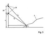
- the portions of the sound signal reflected by the bottom profile 6 within the underwater area 8 are received via the receiving arrangement 28, which in Fig. 3 is shown in detail.
- Fig. 3 shows a schematic representation of the receiving arrangement 28th
- a receiving arrangement 28 with at least two mutually spaced transducers is required.
- the Invention consists of the receiving arrangement 28 of two individual transducers A and B, as in Fig. 3 are shown. They have a distance 30 from one another, which is greater than half the wavelength ⁇ of the output from the transmitting device 20 sound signal.
- the received signals of the transducers A and B are evaluated according to the method according to the invention. You have a path difference ⁇ for ⁇ r proportional phase difference ⁇ on.
- Fig. 4 shows a block diagram of the method according to the invention.
- the received electrical signals 40 and 42 of the transducers A and B are respectively sampled and digitized in processing blocks 44 and 46 at predetermined sampling instants. Further, the N become different from each other Frequencies of the transmission signal from the received signals 40 and 42 filtered out.
- the processing blocks 44 and 46 thus provide N signals: 48 1 , 48 2 , ..., 48 N and 50 1 , 50 2 , 50 3 , ..., 50 N , respectively, which process in parallel for the N different frequencies become.
- the calculation unit 52 both the phase difference ⁇ ⁇ between the signals 48 1 and 50 1 as well as the transit times ⁇ of these signals are determined for a plurality of sampling instants. This is likewise done in the calculation unit 52 2 for the signals 48 2 and 50 2 and in the calculation unit 52 3 for the signals 48 3 and 50 3 , up to the calculation unit 52 N for the signals 48 N and 50 N.
- phase differences ⁇ ⁇ for a variety of sampling and for the N frequencies and the running times ⁇ of the received signals of the transducers A and B determined.
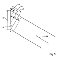
- ⁇ at the determined phase differences ⁇ of the distance 30 the two transducers This is in Fig. 5 shown in detail.
- Fig. 5 shows a schematic representation of an incident on the transducers A and B sound wave front 64. If the distance 30 of the two transducers A and B is greater than half the wavelength ⁇ of the received sound wavefront 64, it comes to ambiguities in the determined phase differences ⁇ ⁇ .
- the phase difference ⁇ calculated ⁇ of the received signals between the transducers A and B is modulo 2 measured ⁇ , thus providing a number of ambiguous path differences ⁇ x 1, ⁇ x 2 ⁇ x 3 depending on the distance 30 of the converters A and B as shown in Fig. 5 exemplified.
- the path difference ⁇ x 3 corresponds, in this exemplary embodiment, the true path difference of the reception signals between the transducers A and B.
- This path difference ⁇ x 3 provides in connection with the spacing 30 of the transducer an associated receiving angle 66 as defined by the sine of an angle at the right-angled triangle , Since the path differences and thus the reception angle 66 are dependent on the wavelength ⁇ of received sound wave front 64, different path differences or receiving angle 66 are determined for each of the N frequencies of the transmission signal.
- the block diagram off Fig. 4 show in a next method step, the calculation unit 54 in the block 54 1 ... 5 4 N for a plurality of sampling times and for the N frequencies by means of the previously determined phase differences ⁇ ⁇ the ambiguous gait differences are determined. These are transferred to the sampling times and for the N frequencies of a further calculation unit 56, which determines therefrom a data density of the path differences.
- the data density represents a measure of the number of data collected and is based on Fig. 6 explained in more detail.
- Fig. 6 shows a schematic representation of the ambiguous gait differences exemplary of four different wavelengths or four different frequencies.
- the path difference is indicated.
- the true retardation is that retardation that belongs to the unique phase difference ⁇ ⁇ of the received signals, which describes the actual path difference ⁇ r of the sound signals of both converters A and B.
- the markings 74 indicate the ambiguous path differences which result from the different phase differences ⁇ ⁇ of different frequencies or wavelengths 76, 78, 80 and 82nd At these points 74, the individual path differences of the four frequencies are slightly offset. To obtain clear results in the measurement of the soil profile, it is necessary to determine the unique phase difference ⁇ ⁇ or the true path difference of the received signals.
- the further calculation unit 56 from Fig. 4 also includes a maximum detector to determine the maximum data density for the sampling instants. For each sampling time at which a path difference has been determined, the one path difference whose associated interval 84 has the greatest data density is marked as valid for the further method. The other ambiguous gait differences associated with this sample time are marked invalid.
- Based on the valid path difference can be in a processing block 58 for the sampling times an associated signal delay time ⁇ of the corresponding received signal and an associated receiving angle 66, respectively Fig. 5 , determine. From these data, an angle of incidence associated with the valid path difference on the soil profile is determined for the sampling times. This is done using known laws of trigonometry of the measurement geometry.
- an associated incidence coordinate (x, y, z) of the soil profile 6 is determined in a processing block 60 at the sampling instants.
- the x-coordinate can be determined at each sampling time by means of the laws of trigonometry, the y-coordinate is dependent on the width 26 of the transmitting team 22 and the z-coordinate corresponds to a height determined from the determined true retardation of the received signals of the transducers A and B. H.
- the coordinate system is related to the watercraft 2 in this embodiment. However, it is also possible to use an absolute coordinate system for carrying out the method if it is taken into account accordingly in the signal processing.
- the above-described method for measuring a soil profile 6 can be modified in such a way that the data density is not raised via the path differences, but from a variable derived from the path difference. This can be, for example, an angle of incidence or an incidence coordinate.
- the size of the area element is determined as a function of the computational effort and is the same for all impact coordinates.
- the incident coordinate whose associated area element has a maximum data density is marked as valid and thus corresponds to the true ground point (x, y, z).
- the other ambiguous landing coordinates are marked as invalid.
- the method described above may be modified such that a transducer array is used instead of two individual transducers as receiving arrangement 28.
- the receiver assembly 28 is followed by a direction generator, which generates in the underwater area 8 a plurality of fan-shaped directional characteristics whose horizontal width is determined by the horizontal opening angle of the directional characteristic. This allows a higher resolution of the survey of the soil profile 6 according to the width of the directional characteristics.
- the underwater area 8 can be spanned on the control and port side of the watercraft 2. As a result, at the same time underwater areas 8 are scanned on both sides in the direction of travel. Furthermore, an underwater area 8 can be illuminated in advance.
Description
Die Erfindung betrifft ein Verfahren zum Vermessen eines Bodenprofils mittels einer an einem Wasserfahrzeug angebrachten akustischen Sende- und Empfangsanordnung der im Oberbegriff des Anspruchs 1 genannten Art sowie eine Vorrichtung zum Ausführen des Verfahrens gemäß Anspruch 4.The invention relates to a method for measuring a soil profile by means of a mounted on a vessel acoustic transmission and reception arrangement referred to in the preamble of claim 1 and a device for carrying out the method according to
Die Erfindung wir primär zur Vermessung eines Bodenprofils innerhalb eines vorbestimmten Unterwasserareals angewandt. Herkömmlicherweise werden zur Vermessung eines Bodenprofils innerhalb eines vorbestimmten Unterwasserareals sog, Fächerlotsysteme eingesetzt. Sie erfassen meist einen bis zu 150 Grad großen Winkelsektor quer zur Fahrtrichtung und vermessen diesen im Wesentlichen gleichzeitig. Dazu werden Schallimpulse ausgesendet, welche nach Reflexion an einem Objekt bzw. dem Gewässergrund als Echos mittels der Empfangsanordnung richtungsselektiv empfangen werden. Durch eine im Rahmen einer sog. Richtungsbildung durchgeführten elektronischen Signalverarbeitung einzelner Empfangssignale der Wandler der Empfangsanordnung wird erreicht, dass die Empfangsanordnung in dem vorbestimmten Unterwasserareal einen Fächer von einer Vielzahl gegeneinander verschwenkter Richtcharakteristiken aufweist.The invention is primarily applied to surveying a soil profile within a predetermined underwater area. Conventionally, for the measurement of a soil profile within a predetermined underwater area, so-called fan plating systems are used. They usually capture an angle sector up to 150 degrees across the direction of travel and measure it essentially simultaneously. For this purpose, sound pulses are emitted which are received in a directionally selective manner as reflections on an object or the bottom of the water as echoes by means of the receiving arrangement. By an electronic signal processing of individual received signals of the transducers of the receiving arrangement carried out as part of a so-called directional formation, it is achieved that the receiving arrangement has a fan of a multiplicity of directional characteristics which are pivoted relative to one another in the predetermined underwater area.
Um bei der Vermessung des Bodenprofils genaue Details der Bodenstruktur oder versunkener Objekte sichtbar zu machen, wird eine hohe Winkelauflösung gefordert. Herkömmlicherweise wird eine hohe Winkelauflösung durch Bündelung der Richtcharakteristik beim Senden und/oder Empfangen erreicht. Eine übliche Maßnahme besteht darin, die Abmessung der Sende- und/oder Empfangsanordnung zu vergrößern, um den Öffnungswinkel ihrer Richtcharakteristik zu verkleinern. Diese Methode setzt jedoch große Wandlerbasen voraus und ist daher sehr kostenintensiv.In order to make precise details of the soil structure or sunken objects visible when measuring the soil profile, a high angular resolution is required. Conventionally, a high angular resolution is achieved by focusing the directional characteristic during transmission and / or reception. A common measure is to increase the size of the transmitting and / or receiving arrangement in order to reduce the opening angle of their directional characteristic. However, this method requires large transducer bases and is therefore very expensive.
Neben dem o.g. Verfahren mittels großer Wandlerbasen als Empfangsanordnung, deren Auflösung durch ihre Bauart beschränkt ist, sind auch sog. hochauflösende Verfahren zur Winkelbestimmung bekannt. Zu diesen Verfahren zählt unter anderem das MUSIC (Multiple Signal Classification)-Verfahren. Die Genauigkeit der Ergebnisse ist jedoch auch bei diesen Verfahren abhängig von der Wandleranzahl der Empfangsanordnung. Je mehr Wandler die Empfangsanordnung besitzt und je länger der verarbeitende Signalblock ist, desto genauer sind die Ergebnisse. Der Nachteil dieser Verfahren liegt zudem in ihrem Rechenaufwand, der einen Einsatz in Echtzeitsystemen erschwert.In addition to the o.g. Method by means of large converter bases as receiving arrangement whose resolution is limited by their design, so-called. High resolution method for angle determination are also known. These methods include, among others, the MUSIC (Multiple Signal Classification) method. However, the accuracy of the results is also dependent on the number of transducers of the receiving arrangement in these methods. The more transducers the receiving arrangement has and the longer the processing signal block is, the more accurate the results. The disadvantage of these methods is also their computational complexity, which makes it difficult to use in real-time systems.
Alternativ sind Sonarsysteme mit interferometrischer Technik bekannt, um die Auflösung bei der Vermessung des Bodenprofils zu erhöhen Sie verwenden eine interferometrische Signalverarbeitung mit bspw. einer Differenzphasenmessung. In dem Artikel "
Herkömmlicherweise wird bei direkter Phasendifferenzmessung ein Sonarsystem mit 3 bis 4 Empfangsantennen verwendet. Damit stehen drei Phasendifferenzen zur Verfügung, die dazu verwendet werden, die gemessenen Phasen zu korrigieren. Der Nachteil dieses Verfahrens ist der ebenfalls hohe Aufwand an Antennen.Conventionally, in direct phase difference measurement, a sonar system having 3 to 4 receiving antennas is used. This provides three phase differences that are used to correct the measured phases. The disadvantage of this method is also the high cost of antennas.
Der Erfindung liegt nach alledem das Problem zugrunde, ein kostengünstiges Verfahren zum Vermessen eines Bodenprofils zu schaffen.The invention is after all the problem of providing a cost-effective method for measuring a soil profile.
Die Erfindung löst dieses Problem durch die Merkmale eines Verfahrens zum Vermessen eines Bodenprofils gemäß Anspruch 1 sowie durch eine entsprechende Vorrichtung mit den Merkmalen des Anspruchs 4. Dabei wird nacheinander mittels einer Sendeanordnung mit einer Mehrzahl N vorbestimmten, voneinander verschiedenen Frequenzen ein Schallsignal in das Unterwasserareal abgestrahlt und dessen vom Bodenprofil reflektierten Anteile mittels einer Empfangsanordnung empfangen, wobei die Empfangsanordnung wenigstens zwei Wandler aufweist, die aus den empfangenen Schallwellen jeweils ein elektrisches Empfangssignal erzeugen und in einem Abstand größer als die halbe Wellenlänge des Empfangssignals angeordnet ist. Aus den Empfangssignalen sind die N verschiedenen Frequenzen des Sendesignals herausfilterbar. Die Vermessung des Bodenprofils erfolgt anhand dieser gefilterten Empfangssignale unter Verwendung einer reinen Phasenauswertung und einer anschließenden Dichteanalyse.The invention solves this problem by the features of a method for measuring a soil profile according to claim 1 and by a corresponding device with the features of
Abhängig von dem Abstand der Wandler der Empfangsanordnung und der Frequenz bzw. der Wellenlänge des ausgesendeten Schallsignals liefert eine reine Phasenauswertung möglicherweise vieldeutige Ergebnisse. Das erfindungsgemäße Verfahren berücksichtigt jedoch zunächst diese Vieldeutigkeit bei der Winkelbestimmung nicht.Depending on the distance of the transducers of the receiving arrangement and the frequency or the wavelength of the emitted sound signal, a pure phase evaluation may yield ambiguous results. However, the method according to the invention initially does not consider this ambiguity in the determination of the angle.
Die durch die vieldeutigen Ergebnisse entstehende Mehrfachmessung mit unterschiedlichen Frequenzen des abgestrahlten Schallsignals wird zur eindeutigen Bestimmung des Bodenprofils unter Verwendung einer Dichteanalyse ausgenutzt. Dabei liefert eine Phasendifferenz zwischen zwei Empfangssignalen zu einer Vielzahl vorbestimmter Abtastzeitpunkte und zu jeder Frequenz des abgestrahlten Schallsignals abhängig von dem Abstand der Wandler der Empfangsanordnung mehrere vieldeutige Gangunterschiede sowie zu diesen Gangunterschieden zugehörige Empfangswinkel. Mithilfe der Laufzeiten und der Empfangswinkel werden für diese Abtastzeitpunkte und für die Frequenzen Auftreffkoordinaten (x, y, z) ermittelt. Anschließend wird für die Auftreffkoordinaten (x, y, z) eine Datendichte innerhalb eines vorbestimmten, die Auftreffkoordinate (x, y, z) beinhaltendes Flächenelementes ermittelt, wobei die Datendichte ein Maß für die Anzahl der zuvor ermittelten Auftreffkoordinaten innerhalb dieses Flächenelementes darstellt.The multiple measurement resulting from the ambiguous results with different frequencies of the radiated sound signal is exploited for unambiguous determination of the soil profile using a density analysis. In this case, a phase difference between two received signals at a plurality of predetermined sampling times and at each frequency of the radiated sound signal depends on the distance of the transducers of the receiving arrangement several ambiguous gait differences and to these gait associated receiving angle. Using the propagation times and the reception angles, incidence coordinates (x, y, z) are determined for these sampling times and for the frequencies. Subsequently, a data density within a predetermined area element containing the incidence coordinate (x, y, z) is determined for the incidence coordinates (x, y, z), wherein the data density represents a measure of the number of previously determined incidence coordinates within this area element.
An der Stelle, an der sich die wahre Auftreffkoordinate (x, y, z) befindet, erhöht sich die Dichte der Messwerte. Die Stellen der weiteren Auftreffkoordinaten, die sich aufgrund der Phasenauswertung ergeben, weisen eine geringere Datendichte auf. Das erfindungsgemäße Verfahren liefert somit eine Methode um festzustellen, welches die wahre Auftreffkoordinate (x, y, z) des Schallsignals ist. Daraus lässt sich ein Bodenprofil ermitteln.At the point where the true incidence coordinate (x, y, z) is located, the density of the measured values increases. The locations of the further impact coordinates, which result from the phase evaluation, have a lower data density. The method according to the invention thus provides a method for determining which is the true incident coordinate (x, y, z) of the sound signal. From this, a soil profile can be determined.
Das erfindungsgemäße Verfahren hat den Vorteil, dass trotz einer zuvor erwähnten Vieldeutigkeit der Winkelbestimmung bei Verwendung einer Empfangsanordnung mit nur zwei Wandlern eindeutige Messergebnisse erzielt werden können, indem die Vermessung des Bodenprofils mit unterschiedlichen Frequenzen erfolgt und anschließend eine Dichteanalyse durchgeführt wird.The inventive method has the advantage that despite an aforementioned ambiguity of the angle determination when using a receiving arrangement with only two transducers unique measurement results can be achieved by the measurement of the soil profile is carried out with different frequencies and then a density analysis is performed.
In einer weiteren Ausführungsform der Erfindung wird die Datendichte nicht über die Auftreffkoordinaten (x, y, z) erhoben, sondern über die aus dem Gangunterschied berechneten Auftreffwinkel.In a further embodiment of the invention, the data density is not collected via the incidence coordinates (x, y, z) but via the angle of incidence calculated from the path difference.
In einer weiteren Ausführungsform der Erfindung besitzt die erfindungsgemäße Vorrichtung den Vorteil, dass sie sich unter Verwendung einer Empfangsanordnung mit zwei einzelnen Wandlern mit sehr kleinen Abmessungen herstellen lässt. Sie kann beispielsweise auch von kleinen, autonomen agierenden oder ferngesteuerten Unterwasserfahrzeugen getragen werden. Das erfindungsgemäße Verfahren nutzt zum Empfangen der von dem Bodenprofil reflektierten Schallwellen eine Empfangsanordnung, welche wenigstens zwei einzelne elektroakustische oder optoakustische Wandler aufweist, die in einem beliebigen Abstand angeordnet sein können.In a further embodiment of the invention, the device according to the invention has the advantage that it can be produced using a receiving arrangement with two individual transducers having very small dimensions. For example, it can also be carried by small, autonomous or remote-controlled underwater vehicles. The method according to the invention utilizes a receiving arrangement for receiving the sound waves reflected by the soil profile, which has at least two individual electroacoustic or optoacoustic transducers which can be arranged at any desired distance.
In einer weiteren Ausführungsform der Erfindung wird als Empfangsvorrichtung ein Wandler-Array verwendet. Ein der Empfangsanordnung nachgeschalteter Richtungsbildner, der in dem Unterwasserareal einen Fächer von einer Vielzahl gegeneinander verschwenkter Richtcharakteristiken erzeugt, hat den Vorteil, die Auflösung des Sonarsystems entsprechend der Breite der Richtcharakteristik zu erhöhen.In a further embodiment of the invention, a transducer array is used as receiving device. A directional generator downstream of the receiving arrangement, which generates a fan of a multiplicity of directional characteristics which are pivoted relative to one another in the underwater area, has the advantage of increasing the resolution of the sonar system in accordance with the width of the directional characteristic.
Weitere vorteilhafte Ausführungsformen ergeben sich aus den Unteransprüchen sowie aus den anhand der anliegenden Zeichnung näher erläuterten Ausführungsbeispielen. In der Zeichnung zeigen:
- Fig. 1
- eine schematische Darstellung eines Wasserfahrzeugs mit dem zu erfassenden Unterwasserareal;
- Fig. 2A-B
- eine schematische Darstellung der Sende- und Empfangsanordnung;
- Fig. 3
- eine schematische Darstellung der Empfangsanordnung;
- Fig. 4
- ein Blockschaltbild des erfindungsgemäßen Verfahrens;
- Fig. 5
- eine schematische Darstellung einer auf die Wandler treffenden Schallwellenfront;
- Fig. 6
- eine schematische Darstellung von vieldeutigen Gangunterschieden.
- Fig. 1
- a schematic representation of a watercraft with the underwater area to be detected;
- Fig. 2A-B
- a schematic representation of the transmitting and receiving arrangement;
- Fig. 3
- a schematic representation of the receiving arrangement;
- Fig. 4
- a block diagram of the method according to the invention;
- Fig. 5
- a schematic representation of an incident on the transducer sound wave front;
- Fig. 6
- a schematic representation of ambiguous gait differences.
In
Ferner ist eine Höhe H in Lotrichtung zu der Sende- und Empfangsanordnung 4 über eine Bezugsebene angegeben.Furthermore, a height H in the perpendicular direction to the transmitting and receiving
Zur Vermessung des Bodenprofils 6 werden von der Sende- und Empfangsanordnung 4 impulsförmige Schallsignale gerichtet in ein Unterwasserareal 8 abgestrahlt und die reflektierten Schallwellen 10 einzelner Bodenpunkte (x, y, z) empfangen. Dabei weist die Sende- und Empfangsanordnung 4 quer zur Fahrtrichtung eine sehr weite Richtcharakteristik und in Fahrzeuglängsrichtung eine stark gebündelte Schallabstrahlung auf. Dadurch werden nur die Echos eines schmalen Bodenstreifens empfangen.To measure the
Die Ausdehnung des beleuchteten Unterwasserareals 8 ist abhängig von der Sende- und Empfangsanordnung 4, welche in
Die Sendeanordnung 20 weist eine Vielzahl auf einem Antennenträger angeordneter Wandler auf, welche gerichtete Schallsignale in Form eines Sendebeams 22 in ein vorbestimmtes Unterwasserareal 8 aussenden. Der so entstehende Sendebeam 22 in Form einer Ellipse hat eine Länge 24 und eine Breite 26, wobei die Form und die Maße abhängig sind von der Anzahl und der Anordnung der Wandler der Sendeanordnung 20.The transmitting
Von dieser Sendeanordnung 20 wird kurz nacheinander mit einer Mehrzahl N vorbestimmten, voneinander verschiedenen Frequenzen ein Schallsignal in das Unterwasserareal 8 gesendet. Die von dem Bodenprofil 6 innerhalb des Unterwasserareals 8 reflektierten Anteile des Schallsignals werden über die Empfangsanordnung 28 empfangen, welche in
Um zusätzlich zu der Entfernung r auch eine Höhe h des Bodenprofils 6 zu ermitteln, wird eine Empfangsanordnung 28, mit wenigstens zwei voneinander beabstandeten Wandlern benötigt. In dieser beispielhaften Ausführungsform der Erfindung besteht die Empfangsanordnung 28 aus zwei einzelnen Wandlern A und B, wie sie in
Es ist jedoch gleichwohl möglich eine vorhandene Wandlerbasis zu nutzen, aus der zwei Wandler herausgegriffen werden. Ebenso ist das erfindungsgemäße Verfahren mit zwei Wandler-Arrays, welche übereinander gemäß
Der Wandler A liefert ein Empfangssignal, welches durch die unterschiedlichen Entfernungen rA und rB zum Bodenpunkt x 0 gegenüber dem Wandler B zeitverzögert ist. Die vom Punkt x 0 reflektierten Anteile des gesendeten Schallsignals erreichen zuerst den Wandler B und um Δt verzögert den Wandler A. Dadurch lässt sich eine Höhe h ermitteln, die bezogen ist auf eine Höhe H der Bezugsebene in Lotrichtung unter der Empfangsanordnung 28.The converter A supplies a received signal, which is delayed in time by the different distances r A and r B to the ground point x 0 with respect to the transducer B. The portions of the transmitted sound signal reflected from the point x 0 first reach the transducer B and Δ t delay the transducer A. As a result, a height h can be determined which is related to a height H of the reference plane in the vertical direction below the receiving
Die Empfangssignale der Wandler A und B werden entsprechend dem erfindungsgemäßen Verfahren ausgewertet. Sie weisen eine zur Wegdifferenz Δr proportionale Phasendifferenz Δϕ auf.The received signals of the transducers A and B are evaluated according to the method according to the invention. You have a path difference φ for Δ r proportional phase difference Δ on.
Die elektrischen Empfangssignale 40 und 42 der Wandler A und B werden jeweils in einem Verarbeitungsblock 44 bzw. 46 zu vorbestimmten Abtastzeitpunkten abgetastet und digitalisiert. Ferner werden die N voneinander verschiedenen Frequenzen des Sendesignals aus den Empfangssignalen 40 und 42 herausgefiltert.The received
Die Verarbeitungsblöcke 44 bzw. 46 liefern somit jeweils N Signale: 481, 482, ...,48N bzw. 501, 502, 503, ..., 50N, die parallel für die N verschiedenen Frequenzen weiterverarbeitet werden. In der Berechnungseinheit 521 werden für eine Vielzahl der Abtastzeitpunkte sowohl die Phasendifferenz Δϕ zwischen den Signalen 481 und 501 als auch die Laufzeiten τ dieser Signale ermittelt. Dies erfolgt ebenso in der Berechnungseinheit 522 für die Signale 482 und 502 sowie in der Berechnungseinheit 523 für die Signale 483 und 503, bis zu der Berechnungseinheit 52N für die Signale 48N und 50N. Auf diese Weise werden für eine Vielzahl der Abtastzeitpunkte und für die N Frequenzen die Phasendifferenzen Δϕ und die Laufzeiten τ der Empfangssignale der Wandler A und B ermittelt. Abhängig von dem Abstand 30 der beiden Wandler sind jedoch Vieldeutigkeiten bei den ermittelten Phasendifferenzen Δϕ möglich. Dies ist in
Der Gangunterschied Δx3 entspricht bei dieser beispielhaften Ausführungsform dem wahren Gangunterschied der Empfangssignale zwischen den Wandlern A und B. Dieser Gangunterschied Δx3 liefert im Zusammenhang mit dem Abstand 30 der Wandler einen zugehörigen Empfangswinkel 66 gemäß der Definition des Sinus eines Winkels am rechtwinkligen Dreieck. Da die Gangunterschiede und damit auch der Empfangswinkel 66 abhängig sind von der Wellenlänge λ der empfangenen Schallwellenfront 64, werden zu jeder der N Frequenzen des Sendesignals verschiedene Gangunterschiede bzw. Empfangswinkel 66 ermittelt.The path difference Δ x 3 corresponds, in this exemplary embodiment, the true path difference of the reception signals between the transducers A and B. This path difference Δ x 3 provides in connection with the spacing 30 of the transducer an associated receiving
Das Blockschaltbild aus
Auf einer horizontal verlaufenden Achse 70 wird der Gangunterschied angegeben. An einer Stelle 72 auf dieser Achse 70 befindet sich der wahre Gangunterschied. Der wahre Gangunterschied ist derjenige Gangunterschied, der zu derjenigen eindeutigen Phasendifferenz Δϕ der Empfangssignale gehört, welcher die tatsächliche Wegdifferenz Δr der Schallsignale beider Wandler A und B beschreibt. An dieser Stelle 72 liegen die einzelnen Gangunterschiede der vier Frequenzen übereinander. Die Markierungen 74 geben die vieldeutigen Gangunterschiede an, welche sich aus den unterschiedlichen Phasendifferenzen Δϕ der unterschiedlichen Frequenzen bzw. Wellenlängen 76, 78, 80 und 82 ergeben. An diesen Stellen 74 sind die einzelnen Gangunterschiede der vier Frequenzen etwas versetzt. Um eindeutige Ergebnisse bei der Vermessung des Bodenprofils zu erhalten, ist es notwendig, die eindeutige Phasendifferenz Δϕ bzw. den wahren Gangunterschied der Empfangssignale zu ermitteln.On a
Dazu wird die Achse 70 in eine Mehrzahl gleichgroßer Intervalle 84 mit einer vorbestimmten, ausreichend kleinen Länge aufgeteilt. Die Länge der Intervalle 84 ist dabei abhängig, wie weit die einzelnen Gangunterschiede minimal versetzt sind. Die Länge der Intervalle 84 darf nicht größer sein, als die geringste Versetzung der Gangunterschiede der kleinsten Wellenlänge zur größten Wellenlänge. Es wird für jedes Intervall 84 eine Datendichte der Gangunterschiede berechnet. Sie ist ein Maß für die Anzahl der Gangunterschiede innerhalb dieses Intervalls. Dasjenige Intervall 84, in dem sich der wahre Gangunterschied befindet, enthält eine maximale Datendichte, da dieses Intervall 84 die Gangunterschiede aller vier Frequenzen beinhaltet.For this purpose, the
Die weitere Berechnungseinheit 56 aus
Anhand des gültigen Gangunterschiedes lässt sich in einem Verarbeitungsblock 58 für die Abtastzeitpunkte eine zugehörige Signallaufzeit τ des entsprechenden, empfangenen Signals und ein zugehöriger Empfangswinkel 66, entsprechend
Aus den zuvor ermittelten Auftreffwinkeln wird in einem Verarbeitungsblock 60 zu den Abtastzeitpunkten eine zugehörige Auftreffkoordinate (x, y, z) des Bodenprofils 6 bestimmt. Die x-Koordinate lässt sich zu jedem Abtastzeitpunkt mittels der Gesetze der Trigonometrie ermitteln, die y-Koordinate ist abhängig von der Breite 26 des Sendebeams 22 und die z-Koordinate entspricht einer aus dem ermittelten wahren Gangunterschied der Empfangssignale der Wandler A und B ermittelten Höhe h.From the previously determined impact angles, an associated incidence coordinate (x, y, z) of the
Das Koordinatensystem ist in diesem Ausführungsbeispiel auf das Wasserfahrzeug 2 bezogen. Es ist jedoch ferner möglich ein absolutes Koordinatensystem für die Durchführung des Verfahrens heranzuziehen, wenn es in der Signalverarbeitung entsprechend berücksichtigt wird.The coordinate system is related to the
Das vorstehend beschriebene Verfahren zur Vermessung eines Bodenprofils 6 kann dahingehend abgewandelt werden, dass die Datendichte nicht über die Gangunterschiede erhoben wird, sondern aus einer aus dem Gangunterschied abgeleiteten Größe. Dies kann bspw. ein Auftreffwinkel oder eine Auftreffkoordinate sein.The above-described method for measuring a
Dazu werden zu den Abtastzeitpunkten, zu denen eine Phasendifferenz Δϕ der Empfangssignale ermittelt wurde, und für die N Frequenzen zunächst zu den vieldeutigen Gangunterschieden die zugehörigen Auftreffwinkel und dann die Auftreffkoordinaten bestimmt. Dies liefert für jede der N Frequenzen vieldeutige Bodenprofile. Die vorhergehenden Schritte des vorstehend beschriebenen Verfahrens bleiben unverändert.For this purpose, at the sampling times at which a phase difference .DELTA..phi. Of the received signals has been determined, and for the N frequencies, first the ambiguous gait differences, the associated angles of incidence and then the incidence coordinates are determined. This provides ambiguous soil profiles for each of the N frequencies. The previous steps of the method described above remain unchanged.
Diese Daten über die vieldeutigen Bodenprofile für die N Frequenzen werden für die Abtastzeitpunkte gesammelt, um mittels einer Dichteanalyse das eindeutige Bodenprofil 6 zu ermitteln. Es werden jedoch nicht, wie zuvor beschrieben, einzelne Intervalle 84 betrachtet, sondern einzelne sog. Flächenelemente. Für die Abtastzeitpunkte, für die N Frequenzen und für jede vieldeutige Auftreffkoordinate wird die Datendichte innerhalb desjenigen Flächenelementes berechnet, welches die Auftreffkoordinate beinhaltet. Dabei ist die Datendichte ein Maß für die Anzahl der erhobenen Daten innerhalb des Flächenelements. Die Auftreffkoordinaten der gleichen Frequenz werden jedoch nicht mit berücksichtigt bei der Ermittlung der Dichte.These data on the ambiguous soil profiles for the N frequencies are collected for the sampling times in order to determine the
Die Größe des Flächenelements wird in Abhängigkeit von dem Rechenaufwand festgelegt und ist für alle Auftreffkoordinaten gleich groß.The size of the area element is determined as a function of the computational effort and is the same for all impact coordinates.
Zu jedem Abtastzeitpunkt wird diejenige Auftreffkoordinate, dessen zugehöriges Flächenelement eine maximale Datendichte besitzt, als gültig gekennzeichnet und entspricht somit dem wahren Bodenpunkt (x, y, z). Die anderen vieldeutigen Auftreffkoordinaten werden als ungültig gekennzeichnet.At each sampling instant, the incident coordinate whose associated area element has a maximum data density is marked as valid and thus corresponds to the true ground point (x, y, z). The other ambiguous landing coordinates are marked as invalid.
Eine derartige Dichteanalyse, wie vorstehend beschrieben, ist ebenso unter Verwendung der Auftreffwinkel möglich.Such a density analysis as described above is also possible using the incident angles.
Das vorstehend beschriebene Verfahren kann dahingehend abgewandelt werden, dass anstelle von zwei einzelnen Wandlern als Empfangsanordnung 28 ein Wandler-Array verwendet wird. Der Empfangsanordnung 28 wird ein Richtungsbildner nachgeschaltet, der in dem Unterwasserareal 8 eine Vielzahl von fächerartig aufgespannten Richtcharakteristiken erzeugt, deren horizontale Breite durch den horizontalen Öffnungswinkel der Richtcharakteristik bestimmt ist. Dies ermöglicht eine höhere Auflösung der Vermessung des Bodenprofils 6 entsprechend der Breite der Richtcharakteristiken.The method described above may be modified such that a transducer array is used instead of two individual transducers as receiving
In Abwandlung des beschriebenen Verfahrens kann das Unterwasserareal 8 auf der Steuer- und Backbordseite des Wasserfahrzeugs 2 aufgespannt werden. Dadurch werden gleichzeitig Unterwasserareale 8 auf beiden Seiten in Fahrtrichtung abgetastet. Ferner kann ein Unterwasserareal 8 in Vorausrichtung beleuchtet werden.In a modification of the described method, the
Alle in der vorgenannten Figurenbeschreibung, in den Ansprüchen und in der Beschreibungseinleitung genannten Merkmale sind sowohl einzeln als auch in beliebiger Kombination miteinander einsetzbar. Die Erfindung ist somit nicht auf die beschriebenen bzw. beanspruchten Merkmalskombinationen beschränkt. Vielmehr sind alle Merkmalskombinationen als offenbart zu betrachten.All mentioned in the above description of the figures, in the claims and in the introduction of the description features can be used individually as well as in any combination with each other. The invention is thus not limited to the described or claimed feature combinations. Rather, all feature combinations are to be regarded as disclosed.
Claims (6)
- Method for measuring a ground profile (6) by means of a transmitting arrangement (20) mounted on a watercraft (2) for the directed emission of acoustic signals into an underwater area (8) and by means of a receiving arrangement (28) mounted on said watercraft (2), which arrangement comprises at least two electroacoustic or optoacoustic transducers for receiving sound waves reflected by the ground profile (6) within the underwater area (8), from which sound waves the transducers respectively produce a received signal (40; 42), which is sampled, digitised and stored at predetermined sampling times, and wherein an acoustic signal is emitted successively into the underwater area (8) by means of the transmitting arrangement (20) with a plurality N of predetermined frequencies that are different from one another, and parts of said signal reflected by the ground profile (6) are received by means of the receiving arrangement (28) and the N different frequencies are filtered out of the received signal (40; 42) and wherein, for a plurality of sampling times and for the N frequencies of the received signals (481, 482, 483, ..., 48 N ; 501, 502, 503, ..., 50 N ) both a phase difference (Δϕ) and a runtime (τ) of these received signals are determined, characterised in that
the electroacoustic or optoacoustic transducers of the receiving arrangement (28) are arranged having a distance (30) greater than half the wavelength (λ) of the received signal (40; 42),
the phase differences (Δϕ) are used to determine path differences resulting therefrom of the received sound waves between two transducers of the receiving arrangement (28) and related receiving angles (66),
incident coordinates (x, y, z) are determined for these sampling times and for the N frequencies by means of the runtimes (τ) and the receiving angles (66),
a data density within a predetermined region containing the incident coordinates (x, y, z) is determined for the incident coordinates (x, y, z), wherein the data density represents a measure for the number of previously determined incident coordinates (x, y, z) within this region,
the region is selected in which the data density is maximal and the incident coordinate (x, y, z) belonging to this region is determined as the true incident coordinate (x, y, z) of the ground profile (6). - Method according to claim 1, characterised in that angles of incidence are calculated from the respective path differences and a data density of the angles of incidence of the reflected sound waves on the ground profile (6) is determined for the plurality of sampling times and for the respective N frequencies in a predetermined area (84).
- Method according to claim 1 or 2, characterised in that the receiving arrangement (28) consists of a plurality of electroacoustic or optoacoustic transducers, whereby the sound waves are received directionally selectively.
- Device for measuring a ground profile (6) by means of a transmitting arrangement (20) mounted on a water craft (2) for the directed emission of acoustic signals into an underwater area (8) and by means of a receiving arrangement (28) mounted on this water craft (2) with at least two transducers for receiving the sound waves reflected from the ground profile (6) within the underwater area (8), from which sound waves the transducers respectively produce a received signal (40; 42) which can be sampled, digitised and stored at predetermined sampling times and wherein an acoustic signal can be emitted successively into the underwater area (8) by means of the transmitting arrangement (20) with a plurality N of predetermined frequencies that are different from one another and parts of said signal reflected by the ground profile (6) can be received by means of the receiving arrangement (28) and the N different frequencies can be filtered out of the received signal (40; 42) and wherein both a phase difference (Δϕ) and a runtime (τ) of these received signals can be determined for a plurality of sampling times and for the N frequencies of the received signals (481, 482, 483, ..., 48 N ; 501, 502, 503, ..., 50 N ), characterised in that
an arrangement of the electroacoustic and/or optoacoustic transducers of the receiving arrangement (28) having a distance (30) greater than half the wavelength (λ) of the received signal (40; 42),
a further calculation unit (54) for determining the path differences of the received sound waves between two transducers of the receiving arrangement (28) resulting from the phase differences (Δϕ),
a further calculation unit (58) for determining a receiving angle (66) related to the path difference,
a further calculation unit (60) for determining incident coordinates (x, y, z) by means of the runtimes (τ) and the receiving angles (66) for these sampling times and for the N frequencies,
a further calculation unit (56) for determining a data density within a predetermined region containing the incident coordinate, wherein the data density represents a measure for the number of previously determined incident coordinates (x, y, z) within this region,
a maximum detector (56) for selecting that region in which the data density is maximal and for determining an incident coordinate (x, y, z) of the ground profile (6) belonging to this region. - Device according to claim 4, characterised in that
a further calculation unit (56) for determining a data density of the angles of incidence of the reflected sound waves by the ground profile (6) for these sampling times and for the respective N frequencies in a predetermined area (84). - Device according to one of claims 4 to 5, characterised in that the receiving arrangement (28) consists of a plurality of electroacoustic or optoacoustic transducers, whereby the sound waves can be received directionally selectively.
Priority Applications (1)
| Application Number | Priority Date | Filing Date | Title |
|---|---|---|---|
| PL10744950T PL2480910T3 (en) | 2009-09-24 | 2010-08-24 | Method and device for measuring a profile of the ground |
Applications Claiming Priority (2)
| Application Number | Priority Date | Filing Date | Title |
|---|---|---|---|
| DE102009042970A DE102009042970A1 (en) | 2009-09-24 | 2009-09-24 | Method and device for measuring a soil profile |
| PCT/EP2010/062346 WO2011036012A1 (en) | 2009-09-24 | 2010-08-24 | Method and device for measuring a profile of the ground |
Publications (2)
| Publication Number | Publication Date |
|---|---|
| EP2480910A1 EP2480910A1 (en) | 2012-08-01 |
| EP2480910B1 true EP2480910B1 (en) | 2014-01-01 |
Family
ID=43064383
Family Applications (1)
| Application Number | Title | Priority Date | Filing Date |
|---|---|---|---|
| EP10744950.6A Active EP2480910B1 (en) | 2009-09-24 | 2010-08-24 | Method and device for measuring a profile of the ground |
Country Status (11)
| Country | Link |
|---|---|
| US (1) | US8730765B2 (en) |
| EP (1) | EP2480910B1 (en) |
| JP (1) | JP5496338B2 (en) |
| KR (1) | KR101331333B1 (en) |
| AU (1) | AU2010297455B2 (en) |
| CA (1) | CA2774758C (en) |
| DE (1) | DE102009042970A1 (en) |
| DK (1) | DK2480910T3 (en) |
| IL (1) | IL218602A0 (en) |
| PL (1) | PL2480910T3 (en) |
| WO (1) | WO2011036012A1 (en) |
Families Citing this family (4)
| Publication number | Priority date | Publication date | Assignee | Title |
|---|---|---|---|---|
| DE102009042970A1 (en) * | 2009-09-24 | 2011-04-07 | Atlas Elektronik Gmbh | Method and device for measuring a soil profile |
| KR101392221B1 (en) * | 2013-01-22 | 2014-05-20 | 국방과학연구소 | Target motion analysis method using geometric constraints |
| KR101978186B1 (en) * | 2017-11-06 | 2019-05-14 | 소나테크 주식회사 | Method for Arranging Array Sensors of Towed Synthetic Aperture Sonar to Gain Interferometric Data |
| KR102421285B1 (en) * | 2021-03-22 | 2022-07-15 | 레드원테크놀러지 주식회사 | 3D visualization method of mud deposition layer in underwater facilities using underwater vehicle and SONAR, and observation system |
Family Cites Families (10)
| Publication number | Priority date | Publication date | Assignee | Title |
|---|---|---|---|---|
| JPS61254879A (en) * | 1985-05-07 | 1986-11-12 | Nec Corp | Sea-bottom prospecting sonic device |
| GB2197952A (en) * | 1986-11-22 | 1988-06-02 | Marconi Co Ltd | Acoustic echo-sounding system |
| US5200931A (en) | 1991-06-18 | 1993-04-06 | Alliant Techsystems Inc. | Volumetric and terrain imaging sonar |
| JP4079251B2 (en) * | 2002-06-27 | 2008-04-23 | 株式会社光電製作所 | Ultrasonic probe |
| JP2004184341A (en) * | 2002-12-05 | 2004-07-02 | Furuno Electric Co Ltd | Azimuth detection device |
| JP4829487B2 (en) * | 2004-08-10 | 2011-12-07 | 古野電気株式会社 | Forward detection sonar and underwater image display device |
| EP1793243A1 (en) | 2005-12-05 | 2007-06-06 | Leica Geosystems AG | Method for resolving a phase ambiguity |
| JP2008076095A (en) * | 2006-09-19 | 2008-04-03 | Denso Corp | Azimuth detecting method, azimuth detection device, and program |
| DE102009042970A1 (en) * | 2009-09-24 | 2011-04-07 | Atlas Elektronik Gmbh | Method and device for measuring a soil profile |
| DE102009042968B4 (en) * | 2009-09-24 | 2011-07-07 | ATLAS ELEKTRONIK GmbH, 28309 | Method and device for measuring a soil profile |
-
2009
- 2009-09-24 DE DE102009042970A patent/DE102009042970A1/en not_active Withdrawn
-
2010
- 2010-08-24 US US13/498,083 patent/US8730765B2/en not_active Expired - Fee Related
- 2010-08-24 DK DK10744950.6T patent/DK2480910T3/en active
- 2010-08-24 CA CA2774758A patent/CA2774758C/en not_active Expired - Fee Related
- 2010-08-24 WO PCT/EP2010/062346 patent/WO2011036012A1/en active Application Filing
- 2010-08-24 PL PL10744950T patent/PL2480910T3/en unknown
- 2010-08-24 JP JP2012530199A patent/JP5496338B2/en not_active Expired - Fee Related
- 2010-08-24 KR KR1020127009789A patent/KR101331333B1/en active IP Right Grant
- 2010-08-24 EP EP10744950.6A patent/EP2480910B1/en active Active
- 2010-08-24 AU AU2010297455A patent/AU2010297455B2/en not_active Ceased
-
2012
- 2012-03-13 IL IL218602A patent/IL218602A0/en active IP Right Grant
Also Published As
| Publication number | Publication date |
|---|---|
| DE102009042970A1 (en) | 2011-04-07 |
| CA2774758C (en) | 2015-04-14 |
| IL218602A0 (en) | 2012-05-31 |
| DK2480910T3 (en) | 2014-02-10 |
| CA2774758A1 (en) | 2011-03-31 |
| AU2010297455B2 (en) | 2014-02-20 |
| JP2013506117A (en) | 2013-02-21 |
| US20120269036A1 (en) | 2012-10-25 |
| US8730765B2 (en) | 2014-05-20 |
| KR20120054653A (en) | 2012-05-30 |
| AU2010297455A1 (en) | 2012-04-12 |
| PL2480910T3 (en) | 2014-04-30 |
| JP5496338B2 (en) | 2014-05-21 |
| WO2011036012A1 (en) | 2011-03-31 |
| EP2480910A1 (en) | 2012-08-01 |
| KR101331333B1 (en) | 2013-11-20 |
Similar Documents
| Publication | Publication Date | Title |
|---|---|---|
| EP2480911B1 (en) | Method and device for measuring a contour of the ground | |
| EP3803454B1 (en) | Synthetic-aperture radar method and synthetic-aperture radar device | |
| DE19633813C2 (en) | Process for the non-destructive three-dimensional detection of structures in buildings | |
| EP1920269B1 (en) | Method for producing a sonar image | |
| DE102012203172A1 (en) | Radar device for calculating angle of incidence of received signals, has storage unit for storing measured mode vector, where angle of incidence of received signals is calculated under utilization of measured mode vector | |
| DE4344509B4 (en) | Method for measuring the acoustic backscattering property of water bodies | |
| EP2480910B1 (en) | Method and device for measuring a profile of the ground | |
| EP1393025B1 (en) | Method for determining the mean speed of sound in a body of water | |
| EP2577348B1 (en) | Method and device for measuring a ground profile | |
| EP2589977B1 (en) | Method and apparatus for correcting systematic DF errors | |
| DE3623521A1 (en) | PASSIVE METHOD FOR ESTIMATING TARGET DATA OF A TARGET EMITTING TIME-CONTINUOUS WATER SOUND SIGNALS | |
| EP2480907B1 (en) | Method and device for locating sound-emitting targets | |
| DE19825271C1 (en) | Procedure for the passive determination of target data | |
| EP1984752B1 (en) | Method for generating a sonar image | |
| DE102004057547B4 (en) | Method and device for the automatic classification of echo signals caused by underwater sound sources | |
| EP2594958B1 (en) | Device and method for acoustic measurement of the bed of a body of water | |
| DE102005061149B4 (en) | Method for generating a sonar image | |
| CN110196426B (en) | Steady three-subarray passive ranging method based on frequency component correction and diagonal loading | |
| EP2333574A2 (en) | Method and device for improving measurement accuracy and sonar assembly | |
| EP1160584B1 (en) | Method for determining direction and/or distance to reflecting targets | |
| DE102021213495A1 (en) | radar measurement method | |
| WO2014117767A1 (en) | Underwater sound signal, underwater transmitter or underwater receiver, underwater sonar, underwater vehicle and retrofitting kit | |
| DD240825A3 (en) | LOCATION PROCESS WITH DIRECTIONS, ESPECIALLY FOR THE PANORAMIC PRESENTATION OF ROOMED AND / OR LIGHTED ROOMS, PREFERABLY OF UNDERWATER ROOMS |
Legal Events
| Date | Code | Title | Description |
|---|---|---|---|
| PUAI | Public reference made under article 153(3) epc to a published international application that has entered the european phase |
Free format text: ORIGINAL CODE: 0009012 |
|
| 17P | Request for examination filed |
Effective date: 20120320 |
|
| AK | Designated contracting states |
Kind code of ref document: A1 Designated state(s): AL AT BE BG CH CY CZ DE DK EE ES FI FR GB GR HR HU IE IS IT LI LT LU LV MC MK MT NL NO PL PT RO SE SI SK SM TR |
|
| DAX | Request for extension of the european patent (deleted) | ||
| GRAP | Despatch of communication of intention to grant a patent |
Free format text: ORIGINAL CODE: EPIDOSNIGR1 |
|
| INTG | Intention to grant announced |
Effective date: 20130913 |
|
| GRAS | Grant fee paid |
Free format text: ORIGINAL CODE: EPIDOSNIGR3 |
|
| GRAA | (expected) grant |
Free format text: ORIGINAL CODE: 0009210 |
|
| AK | Designated contracting states |
Kind code of ref document: B1 Designated state(s): AL AT BE BG CH CY CZ DE DK EE ES FI FR GB GR HR HU IE IS IT LI LT LU LV MC MK MT NL NO PL PT RO SE SI SK SM TR |
|
| REG | Reference to a national code |
Ref country code: GB Ref legal event code: FG4D Free format text: NOT ENGLISH |
|
| REG | Reference to a national code |
Ref country code: CH Ref legal event code: EP |
|
| REG | Reference to a national code |
Ref country code: IE Ref legal event code: FG4D Free format text: LANGUAGE OF EP DOCUMENT: GERMAN |
|
| REG | Reference to a national code |
Ref country code: DK Ref legal event code: T3 Effective date: 20140206 |
|
| REG | Reference to a national code |
Ref country code: AT Ref legal event code: REF Ref document number: 647819 Country of ref document: AT Kind code of ref document: T Effective date: 20140215 |
|
| REG | Reference to a national code |
Ref country code: DE Ref legal event code: R096 Ref document number: 502010005844 Country of ref document: DE Effective date: 20140220 |
|
| REG | Reference to a national code |
Ref country code: SE Ref legal event code: TRGR |
|
| REG | Reference to a national code |
Ref country code: NL Ref legal event code: T3 |
|
| REG | Reference to a national code |
Ref country code: PL Ref legal event code: T3 |
|
| REG | Reference to a national code |
Ref country code: NO Ref legal event code: T2 Effective date: 20140101 |
|
| REG | Reference to a national code |
Ref country code: LT Ref legal event code: MG4D |
|
| PG25 | Lapsed in a contracting state [announced via postgrant information from national office to epo] |
Ref country code: IS Free format text: LAPSE BECAUSE OF FAILURE TO SUBMIT A TRANSLATION OF THE DESCRIPTION OR TO PAY THE FEE WITHIN THE PRESCRIBED TIME-LIMIT Effective date: 20140501 Ref country code: LT Free format text: LAPSE BECAUSE OF FAILURE TO SUBMIT A TRANSLATION OF THE DESCRIPTION OR TO PAY THE FEE WITHIN THE PRESCRIBED TIME-LIMIT Effective date: 20140101 |
|
| PG25 | Lapsed in a contracting state [announced via postgrant information from national office to epo] |
Ref country code: FI Free format text: LAPSE BECAUSE OF FAILURE TO SUBMIT A TRANSLATION OF THE DESCRIPTION OR TO PAY THE FEE WITHIN THE PRESCRIBED TIME-LIMIT Effective date: 20140101 Ref country code: ES Free format text: LAPSE BECAUSE OF FAILURE TO SUBMIT A TRANSLATION OF THE DESCRIPTION OR TO PAY THE FEE WITHIN THE PRESCRIBED TIME-LIMIT Effective date: 20140101 Ref country code: CY Free format text: LAPSE BECAUSE OF FAILURE TO SUBMIT A TRANSLATION OF THE DESCRIPTION OR TO PAY THE FEE WITHIN THE PRESCRIBED TIME-LIMIT Effective date: 20140101 Ref country code: PT Free format text: LAPSE BECAUSE OF FAILURE TO SUBMIT A TRANSLATION OF THE DESCRIPTION OR TO PAY THE FEE WITHIN THE PRESCRIBED TIME-LIMIT Effective date: 20140502 |
|
| PG25 | Lapsed in a contracting state [announced via postgrant information from national office to epo] |
Ref country code: LV Free format text: LAPSE BECAUSE OF FAILURE TO SUBMIT A TRANSLATION OF THE DESCRIPTION OR TO PAY THE FEE WITHIN THE PRESCRIBED TIME-LIMIT Effective date: 20140101 Ref country code: HR Free format text: LAPSE BECAUSE OF FAILURE TO SUBMIT A TRANSLATION OF THE DESCRIPTION OR TO PAY THE FEE WITHIN THE PRESCRIBED TIME-LIMIT Effective date: 20140101 |
|
| REG | Reference to a national code |
Ref country code: DE Ref legal event code: R097 Ref document number: 502010005844 Country of ref document: DE |
|
| PG25 | Lapsed in a contracting state [announced via postgrant information from national office to epo] |
Ref country code: RO Free format text: LAPSE BECAUSE OF FAILURE TO SUBMIT A TRANSLATION OF THE DESCRIPTION OR TO PAY THE FEE WITHIN THE PRESCRIBED TIME-LIMIT Effective date: 20140101 Ref country code: EE Free format text: LAPSE BECAUSE OF FAILURE TO SUBMIT A TRANSLATION OF THE DESCRIPTION OR TO PAY THE FEE WITHIN THE PRESCRIBED TIME-LIMIT Effective date: 20140101 Ref country code: CZ Free format text: LAPSE BECAUSE OF FAILURE TO SUBMIT A TRANSLATION OF THE DESCRIPTION OR TO PAY THE FEE WITHIN THE PRESCRIBED TIME-LIMIT Effective date: 20140101 |
|
| PLBE | No opposition filed within time limit |
Free format text: ORIGINAL CODE: 0009261 |
|
| STAA | Information on the status of an ep patent application or granted ep patent |
Free format text: STATUS: NO OPPOSITION FILED WITHIN TIME LIMIT |
|
| PG25 | Lapsed in a contracting state [announced via postgrant information from national office to epo] |
Ref country code: SK Free format text: LAPSE BECAUSE OF FAILURE TO SUBMIT A TRANSLATION OF THE DESCRIPTION OR TO PAY THE FEE WITHIN THE PRESCRIBED TIME-LIMIT Effective date: 20140101 |
|
| 26N | No opposition filed |
Effective date: 20141002 |
|
| REG | Reference to a national code |
Ref country code: DE Ref legal event code: R097 Ref document number: 502010005844 Country of ref document: DE Effective date: 20141002 |
|
| PG25 | Lapsed in a contracting state [announced via postgrant information from national office to epo] |
Ref country code: LU Free format text: LAPSE BECAUSE OF FAILURE TO SUBMIT A TRANSLATION OF THE DESCRIPTION OR TO PAY THE FEE WITHIN THE PRESCRIBED TIME-LIMIT Effective date: 20140824 Ref country code: MC Free format text: LAPSE BECAUSE OF FAILURE TO SUBMIT A TRANSLATION OF THE DESCRIPTION OR TO PAY THE FEE WITHIN THE PRESCRIBED TIME-LIMIT Effective date: 20140101 |
|
| REG | Reference to a national code |
Ref country code: CH Ref legal event code: PL |
|
| PG25 | Lapsed in a contracting state [announced via postgrant information from national office to epo] |
Ref country code: LI Free format text: LAPSE BECAUSE OF NON-PAYMENT OF DUE FEES Effective date: 20140831 Ref country code: CH Free format text: LAPSE BECAUSE OF NON-PAYMENT OF DUE FEES Effective date: 20140831 Ref country code: BE Free format text: LAPSE BECAUSE OF NON-PAYMENT OF DUE FEES Effective date: 20140831 |
|
| REG | Reference to a national code |
Ref country code: IE Ref legal event code: MM4A |
|
| PG25 | Lapsed in a contracting state [announced via postgrant information from national office to epo] |
Ref country code: SI Free format text: LAPSE BECAUSE OF FAILURE TO SUBMIT A TRANSLATION OF THE DESCRIPTION OR TO PAY THE FEE WITHIN THE PRESCRIBED TIME-LIMIT Effective date: 20140101 |
|
| PG25 | Lapsed in a contracting state [announced via postgrant information from national office to epo] |
Ref country code: IE Free format text: LAPSE BECAUSE OF NON-PAYMENT OF DUE FEES Effective date: 20140824 |
|
| PG25 | Lapsed in a contracting state [announced via postgrant information from national office to epo] |
Ref country code: SM Free format text: LAPSE BECAUSE OF FAILURE TO SUBMIT A TRANSLATION OF THE DESCRIPTION OR TO PAY THE FEE WITHIN THE PRESCRIBED TIME-LIMIT Effective date: 20140101 |
|
| PG25 | Lapsed in a contracting state [announced via postgrant information from national office to epo] |
Ref country code: BG Free format text: LAPSE BECAUSE OF FAILURE TO SUBMIT A TRANSLATION OF THE DESCRIPTION OR TO PAY THE FEE WITHIN THE PRESCRIBED TIME-LIMIT Effective date: 20140101 Ref country code: MT Free format text: LAPSE BECAUSE OF FAILURE TO SUBMIT A TRANSLATION OF THE DESCRIPTION OR TO PAY THE FEE WITHIN THE PRESCRIBED TIME-LIMIT Effective date: 20140101 Ref country code: IT Free format text: LAPSE BECAUSE OF FAILURE TO SUBMIT A TRANSLATION OF THE DESCRIPTION OR TO PAY THE FEE WITHIN THE PRESCRIBED TIME-LIMIT Effective date: 20140101 Ref country code: GR Free format text: LAPSE BECAUSE OF FAILURE TO SUBMIT A TRANSLATION OF THE DESCRIPTION OR TO PAY THE FEE WITHIN THE PRESCRIBED TIME-LIMIT Effective date: 20140402 |
|
| PG25 | Lapsed in a contracting state [announced via postgrant information from national office to epo] |
Ref country code: HU Free format text: LAPSE BECAUSE OF FAILURE TO SUBMIT A TRANSLATION OF THE DESCRIPTION OR TO PAY THE FEE WITHIN THE PRESCRIBED TIME-LIMIT; INVALID AB INITIO Effective date: 20100824 |
|
| REG | Reference to a national code |
Ref country code: FR Ref legal event code: PLFP Year of fee payment: 7 |
|
| REG | Reference to a national code |
Ref country code: AT Ref legal event code: MM01 Ref document number: 647819 Country of ref document: AT Kind code of ref document: T Effective date: 20150824 |
|
| PG25 | Lapsed in a contracting state [announced via postgrant information from national office to epo] |
Ref country code: AT Free format text: LAPSE BECAUSE OF NON-PAYMENT OF DUE FEES Effective date: 20150824 |
|
| REG | Reference to a national code |
Ref country code: FR Ref legal event code: PLFP Year of fee payment: 8 |
|
| PG25 | Lapsed in a contracting state [announced via postgrant information from national office to epo] |
Ref country code: MK Free format text: LAPSE BECAUSE OF FAILURE TO SUBMIT A TRANSLATION OF THE DESCRIPTION OR TO PAY THE FEE WITHIN THE PRESCRIBED TIME-LIMIT Effective date: 20140101 |
|
| REG | Reference to a national code |
Ref country code: FR Ref legal event code: PLFP Year of fee payment: 9 |
|
| PG25 | Lapsed in a contracting state [announced via postgrant information from national office to epo] |
Ref country code: AL Free format text: LAPSE BECAUSE OF FAILURE TO SUBMIT A TRANSLATION OF THE DESCRIPTION OR TO PAY THE FEE WITHIN THE PRESCRIBED TIME-LIMIT Effective date: 20140101 |
|
| PGFP | Annual fee paid to national office [announced via postgrant information from national office to epo] |
Ref country code: DE Payment date: 20200819 Year of fee payment: 11 Ref country code: FR Payment date: 20200821 Year of fee payment: 11 Ref country code: TR Payment date: 20200819 Year of fee payment: 11 Ref country code: NL Payment date: 20200826 Year of fee payment: 11 Ref country code: GB Payment date: 20200826 Year of fee payment: 11 Ref country code: DK Payment date: 20200821 Year of fee payment: 11 Ref country code: NO Payment date: 20200821 Year of fee payment: 11 |
|
| PGFP | Annual fee paid to national office [announced via postgrant information from national office to epo] |
Ref country code: SE Payment date: 20200826 Year of fee payment: 11 Ref country code: PL Payment date: 20200814 Year of fee payment: 11 |
|
| REG | Reference to a national code |
Ref country code: DE Ref legal event code: R119 Ref document number: 502010005844 Country of ref document: DE |
|
| REG | Reference to a national code |
Ref country code: DK Ref legal event code: EBP Effective date: 20210831 |
|
| REG | Reference to a national code |
Ref country code: NO Ref legal event code: MMEP |
|
| REG | Reference to a national code |
Ref country code: SE Ref legal event code: EUG |
|
| REG | Reference to a national code |
Ref country code: NL Ref legal event code: MM Effective date: 20210901 |
|
| GBPC | Gb: european patent ceased through non-payment of renewal fee |
Effective date: 20210824 |
|
| PG25 | Lapsed in a contracting state [announced via postgrant information from national office to epo] |
Ref country code: SE Free format text: LAPSE BECAUSE OF NON-PAYMENT OF DUE FEES Effective date: 20210825 Ref country code: NO Free format text: LAPSE BECAUSE OF NON-PAYMENT OF DUE FEES Effective date: 20210831 |
|
| PG25 | Lapsed in a contracting state [announced via postgrant information from national office to epo] |
Ref country code: NL Free format text: LAPSE BECAUSE OF NON-PAYMENT OF DUE FEES Effective date: 20210901 |
|
| PG25 | Lapsed in a contracting state [announced via postgrant information from national office to epo] |
Ref country code: GB Free format text: LAPSE BECAUSE OF NON-PAYMENT OF DUE FEES Effective date: 20210824 Ref country code: FR Free format text: LAPSE BECAUSE OF NON-PAYMENT OF DUE FEES Effective date: 20210831 Ref country code: DK Free format text: LAPSE BECAUSE OF NON-PAYMENT OF DUE FEES Effective date: 20210831 Ref country code: DE Free format text: LAPSE BECAUSE OF NON-PAYMENT OF DUE FEES Effective date: 20220301 |