EP2480865B1 - Strömungsmessung mit nahfeld-mikrowellen - Google Patents
Strömungsmessung mit nahfeld-mikrowellen Download PDFInfo
- Publication number
- EP2480865B1 EP2480865B1 EP10760851.5A EP10760851A EP2480865B1 EP 2480865 B1 EP2480865 B1 EP 2480865B1 EP 10760851 A EP10760851 A EP 10760851A EP 2480865 B1 EP2480865 B1 EP 2480865B1
- Authority
- EP
- European Patent Office
- Prior art keywords
- process fluid
- microwave signal
- microwave
- near field
- flow rate
- Prior art date
- Legal status (The legal status is an assumption and is not a legal conclusion. Google has not performed a legal analysis and makes no representation as to the accuracy of the status listed.)
- Active
Links
Images

Classifications
-
- G—PHYSICS
- G01—MEASURING; TESTING
- G01F—MEASURING VOLUME, VOLUME FLOW, MASS FLOW OR LIQUID LEVEL; METERING BY VOLUME
- G01F1/00—Measuring the volume flow or mass flow of fluid or fluent solid material wherein the fluid passes through a meter in a continuous flow
- G01F1/74—Devices for measuring flow of a fluid or flow of a fluent solid material in suspension in another fluid
-
- G—PHYSICS
- G01—MEASURING; TESTING
- G01F—MEASURING VOLUME, VOLUME FLOW, MASS FLOW OR LIQUID LEVEL; METERING BY VOLUME
- G01F1/00—Measuring the volume flow or mass flow of fluid or fluent solid material wherein the fluid passes through a meter in a continuous flow
- G01F1/66—Measuring the volume flow or mass flow of fluid or fluent solid material wherein the fluid passes through a meter in a continuous flow by measuring frequency, phase shift or propagation time of electromagnetic or other waves, e.g. using ultrasonic flowmeters
-
- G—PHYSICS
- G01—MEASURING; TESTING
- G01F—MEASURING VOLUME, VOLUME FLOW, MASS FLOW OR LIQUID LEVEL; METERING BY VOLUME
- G01F1/00—Measuring the volume flow or mass flow of fluid or fluent solid material wherein the fluid passes through a meter in a continuous flow
- G01F1/66—Measuring the volume flow or mass flow of fluid or fluent solid material wherein the fluid passes through a meter in a continuous flow by measuring frequency, phase shift or propagation time of electromagnetic or other waves, e.g. using ultrasonic flowmeters
- G01F1/667—Arrangements of transducers for ultrasonic flowmeters; Circuits for operating ultrasonic flowmeters
Definitions
- the present invention relates to industrial process controlled monitoring systems. More particularly, the particular invention relates to measurement of flow of multiphase in industrial processes.
- WO 2008/085065 A describes a sensor for measuring a flow of a liquid.
- a dielectric resonator sensor is applying a fringing electromagnetic field.
- a resulting resonance frequency is measured.
- Based on the measured resonance frequency a flow of the liquid is determined.
- US 5,900,618 describes a microwave microscope. A conductivity of a probe and a capacity between the probe and a sample are measured in order to determine properties of the probe.
- Oil production from such wells is characterized by a multiphase mixture of water, oil, natural gas and sand.
- To monitor the flow rate of such wells there are a number of multiphase flow measurement techniques using gamma ray, IR, microwave and ultrasonic sensors, often in combination with a mechanical separation system that creates a bulky and expensive installation.
- Radioactive sources are frequently not attractive due to their handling in production. Further, disposal at end-of-life creates a potential hazard.
- Optical/IR methods may suffer from the sensitivity of optical parts to a dirty environment. Ultrasonic sensors, while having attractive resolution properties, may suffer similarly from sand and dirt, leading to high losses. or high power requirements. While each of the methods also has their merits, microwaves may be used more effectively to characterize multiphase flows.
- the present invention includes the use of a local statistical measurement to characterize the flow.
- Near field microwave microscopy can be used to determine the structure of dielectric materials at resolutions comparable to lateral extension of a transmission line (TL) tip that scans a surface area.
- TL transmission line
- such instruments can be achieved with micromachined probe tips to cover a length typical for the minimal feature size in multiphase flow, for example, a few millimeters.
- Mechanical scanning is not necessary because the fluid flow itself moves thereby providing a "scanning" of the mixture as it moves by the probe.
- the modulation properties of the reflected microwave signal can be used as a measure and discriminator of the local constituents of the flow, i.e. the passage of a certain droplet volume will induce a modulation of the field typical for size of the droplet.
- the concentration and nature of the embedded features can be measured in approximately the same way as shot noise of an electric current can be used to determine the typical size of the charges that are transported.
- statistics of the dynamic changes at a local point are used to estimate volumetric information.
- a statistical sampling technique is used to determine flow rate by extrapolating a local measurement to thereby infer the flow rate and composition of the total volume of fluid.
- FIG. 1 is a simplified diagram of an industrial process 10 including a flowmeter or process device coupled to process piping 14.
- Process piping 14 carries a process fluid 16 which flows therethrough in the direction indicated.
- Flowmeter 12 can be of any particular configuration or design and is configured to measure flow of fluid 16, such as a multiphase fluid, through process piping 14.
- the flowmeter 12 is shown as being coupled to a remote control room 20 by a process control loop 22.
- the process control loop 22 can be in accordance with any configuration such as a two-wire control loop based upon the HART® communication protocol, a 4-20 mA process control loop, a FieldBus based protocol, a wireless communication protocol, or others.
- Flowmeter 12 includes a near field microwave probe 30 arranged to interact in the near field with process fluid 16. As discussed herein, near field microwave measurements are used to determine the flow rate of process fluid 16 through process piping 14.
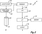
- FIG. 2 is a simplified block diagram of flow measurement device 12 illustrating one example configuration.
- flow measurement device 12 includes a microwave source 100 which is configured to generate microwave signals provided to directional coupler 102.
- a coaxial cable 104 couples to a microwave probe tip 30 which is immersed in process fluid 16.
- Probe 30 interacts with the process fluid 30 in the near field through process fluid 16 in the near field with respect to the frequency of the microwaves generated by microwave source 100.
- the near field can be defined as measurements occurring within a distance which is much less than the wavelength of the microwaves.
- the microwave near field interaction with process fluid 16 provides a microwave reflection signal back through probe 30, and coaxial cable 104 to directional coupler 102.
- This reflection signal is related to the size, shape, consistency, permeability, area, volume, and other features of components in a multiphase process fluid such as fluid 16.
- the "reflected signal” may be an electrical signal carried by probe 30 or may be an electrical characteristic of probe 30 which is measured with appropriate equipment.
- Directional coupler 102 provides the reflective signal to feedback circuitry 106.
- Feedback circuitry 106 is used to control microwave source 100 in accordance with known techniques.
- An output 108 from feedback circuitry 106 is provided to an analog to digital converter 110.
- the output 108 can comprise, for example, a voltage signal which is related to the near field reflection from the process fluid 16.
- a microprocessor 112 is configured to analyze the output from the analog to digital converter 110.
- Microprocessor 112 operates in accordance with instructions stored in a memory 114.
- the memory 114 can also be used for temporary or permanent storage of other data or information including configuration data.
- Microprocessor 112 performs a statistical analysis on the output from analog to digital converter 112. For example, the frequency of peaks in the signal, the width of peaks in the output signal, the duration of peaks or other variations in the signal can be monitored and statistically analyzed. Statistics include average, median, variance, and spatial and temporal correlation coefficients etc. This data can be correlated with the flow rate of the process fluid 16.
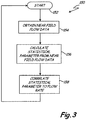
- FIG 3 is a simplified flowchart showing steps in accordance with the present invention. These steps can be performed, for example, by device 12 shown above.
- the flowchart 150 begins at start block 152.
- near field based flow data is obtained, for example, using the circuitry illustrated in Figure 2 .
- a statistical parameter is calculated from the near field based flow data. This statistical parameter is then correlated to a flow rate at block 158.
- a statistical parameter which identifies the average number of data peaks over a period of time can be used and correlated to a flow rate of the process fluid 16. This correlation can be determined experimentally and can be performed using known techniques such as through a polynomial curve field.
- a near field probe is the ability to achieve a resolution that is suitable to characterize the features of the multi-phase flow, i.e. the ability to resolve the actual constituents at a given point in time. For some fluids, this cannot be achieved with the centimeter or larger wavelengths using the propagating modes used in current microwave multiphase flow sensors. While the propagating/resonant modes used typically require a certain geometry and/or metallic pipe walls, a near field probe is only dependent on the electromagnetic response in an area comparable to the probe lateral extension. The probe can be shaped to contain the complete circumference of the pipe, or several sensors may be used to obtain more accurate measurements. The local near field can be made significantly larger than the propagating field strength with the power restrictions applicable for industrial sensors.
- the use of several near field sensors may be used to measure typical relaxation effects that can further be used to characterize the fluid properties (e.g. Doppler of transmitted/reflected field as a function of polarizing field) giving additional information on the fluid at the point of measurement.
- This idea builds on the polarizability of the natural gas phase (methane), which has a measurable polarizability.
- An intense, pulsed electric field could therefore induce an electric dipole moment, which then decay and respond/reflect to microwave probing fields in an anisotropic pattern and with a certain Doppler shift, i.e. like a small moving microwave antenna.
- Electric and magnetic susceptibility is usually quenched in the liquid phase, where the molecular interactions dominate over external electromagnetic field effects.
- a microwave detector is used to measure the reflected near field signal.
- this detector is formed by the directional coupler 102, feedback circuit 106, analog to digital converter 110.
- the present invention is not limited to this particular type of near field microwave detector and other circuits and configurations may be employed. This embodiment is provided for exemplary purposes only.
- the microprocessor provides a flow calculation circuit for use in determining the flow rate.
- the microwaves discussed herein can be of a frequency range between about 0.3 GHz and about 3 GHz. Although only a single probe is shown, the invention may be implemented with multiple probes or through other techniques.
Landscapes
- Physics & Mathematics (AREA)
- Fluid Mechanics (AREA)
- General Physics & Mathematics (AREA)
- Electromagnetism (AREA)
- Measuring Volume Flow (AREA)
Claims (15)
- Strömungsmesser zum Messen der Strömungsrate eines Prozessfluids (16), umfassend:eine Mikrowellenquelle (100), die dafür ausgebildet ist, ein Mikrowellensignal zu generieren;eine Sondenspitze (30), die mit der Mikrowellenquelle (100) gekoppelt ist, in das Prozessfluid (16) eingetaucht ist, sich in Nahbereichsnähe zu dem Prozessfluid (16) befindet und dafür ausgebildet ist, das Mikrowellensignal an das Prozessfluid (16) anzulegen;einen Mikrowellendetektor, der mit der Sondenspitze (30) gekoppelt ist, die dafür ausgebildet ist, ein reflektiertes Nahbereichs-Mikrowellensignal von dem Prozessfluid (16) in Reaktion auf das angelegte Mikrowellensignal zu detektieren; undeine Strömungsberechnungsschaltung, die dafür ausgebildet ist, eine Strömungsrate und/oder eine Strömungszusammensetzung des Prozessfluids (16) als eine Funktion des detektierten Mikrowellensignals zu bestimmen;wobei die Strömungsberechnungsschaltung einen statistischen Parameter des reflektierten Nahbereichs-Mikrowellensignals berechnet und den berechneten statistischen Parameter mit einer Strömungsrate korreliert.
- Vorrichtung nach Anspruch 1, die einen Richtungskoppler (102) umfasst, die mit der Sondenspitze gekoppelt sind.
- Vorrichtung nach Anspruch 1, die eine Rückkopplungsschaltung (106) umfasst, die dafür ausgebildet ist, ein Ausgangssignal auf der Basis des reflektierten Mikrowellensignals bereitzustellen.
- Vorrichtung nach Anspruch 3, die einen Analog-Digital-Wandler (110) umfasst, der dafür ausgebildet ist, ein digitales Ausgangssignal auf der Basis eines Ausgangssignals von der Rückkopplungsschaltung (106), das zu dem reflektierten Mikrowellensignal in Beziehung steht, bereitzustellen.
- Vorrichtung nach Anspruch 1, wobei die Strömungsberechnungsschaltung einen Mikroprozessor (112) umfasst.
- Vorrichtung nach Anspruch 1, wobei der statistische Parameter einen Durchschnitt umfasst.
- Vorrichtung nach Anspruch 1, die ein Koaxialkabel (104) umfasst, das die Mikrowellenquelle (100) mit der Sondenspitze (30) koppelt.
- Vorrichtung nach Anspruch 1, wobei das Prozessfluid (16) ein Multiphasen-Prozessfluid umfasst.
- Verfahren zum Messen der Strömungsrate eines Prozessfluids (16), umfassend:Generieren eines Mikrowellensignals aus einer Mikrowellenquelle (100);Anlegen eines Mikrowellensignals an das Prozessfluid (16) mit einer Sondenspitze (30), die in das Prozessfluid (16) eingetaucht ist und sich in Nahbereichsnähe zu dem Prozessfluid (16) befindet;Detektieren eines reflektierten Nahbereichs-Mikrowellensignals von der Sondenspitze (30), das in Reaktion auf das angelegte Mikrowellensignal generiert wird; undBestimmen einer Strömungsrate des Prozessfluids (16) als eine Funktion des detektierten Mikrowellensignals;wobei das Bestimmen einer Strömungsrate das Berechnen eines statistischen Parameters des reflektierten Nahbereichs-Mikrowellensignals und das Korrelieren des berechneten statistischen Parameters mit einer Strömungsrate umfasst.
- Verfahren nach Anspruch 9, welches das Bereitstellen eines Richtungskopplers (102) umfasst, der mit der Sondenspitze (30) gekoppelt ist.
- Verfahren nach Anspruch 9, welches das Bereitstellen einer Rückkopplungsschaltung (106) umfasst, die dafür ausgebildet ist, ein Ausgangssignal auf der Basis des reflektierten Mikrowellensignals bereitzustellen.
- Verfahren nach Anspruch 11, welches das Umwandeln eines Ausgangssignals von der Rückkopplungsschaltung (106), das zu dem reflektierten Mikrowellensignal in Beziehung steht, zu einem digitalen Signal umfasst.
- Verfahren nach Anspruch 9, wobei der statistische Parameter einen Durchschnitt umfasst.
- Verfahren nach Anspruch 9, welches das Bereitstellen eines Koaxialkabels (104) umfasst, das die Mikrowellenquelle (100) mit der Sondenspitze (30) koppelt.
- Verfahren nach Anspruch 9, wobei das Prozessfluid (16) ein Multiphasen-Prozessfluid enthält.
Applications Claiming Priority (2)
| Application Number | Priority Date | Filing Date | Title |
|---|---|---|---|
| US12/566,996 US8028588B2 (en) | 2009-09-25 | 2009-09-25 | Flow measurement using near field microwaves |
| PCT/US2010/049585 WO2011037887A2 (en) | 2009-09-25 | 2010-09-21 | Flow measurement using near field microwaves |
Publications (2)
| Publication Number | Publication Date |
|---|---|
| EP2480865A2 EP2480865A2 (de) | 2012-08-01 |
| EP2480865B1 true EP2480865B1 (de) | 2017-12-20 |
Family
ID=43778809
Family Applications (1)
| Application Number | Title | Priority Date | Filing Date |
|---|---|---|---|
| EP10760851.5A Active EP2480865B1 (de) | 2009-09-25 | 2010-09-21 | Strömungsmessung mit nahfeld-mikrowellen |
Country Status (6)
| Country | Link |
|---|---|
| US (1) | US8028588B2 (de) |
| EP (1) | EP2480865B1 (de) |
| JP (1) | JP5485401B2 (de) |
| CN (1) | CN102369417B (de) |
| CA (1) | CA2775069C (de) |
| WO (1) | WO2011037887A2 (de) |
Families Citing this family (8)
| Publication number | Priority date | Publication date | Assignee | Title |
|---|---|---|---|---|
| JP6066551B2 (ja) * | 2011-12-01 | 2017-01-25 | 株式会社Wadeco | 管内を流れる粉体または流体の濃度または流量の測定方法、並びにそのための測定装置 |
| CN103336273B (zh) * | 2013-05-24 | 2015-11-25 | 中国电子科技集团公司第四十一研究所 | 一种基于波谱域补偿的探头耦合消除方法 |
| DE102013018386A1 (de) * | 2013-11-04 | 2015-05-07 | Krohne Messtechnik Gmbh | Verfahren und Vorrichtung zur Bestimmung der Geschwindigkeit eines Mediums |
| CN105738956B (zh) * | 2016-04-01 | 2017-12-01 | 北京天凯华尊科技有限公司 | 微波流量探测器 |
| WO2018148756A1 (en) | 2017-02-13 | 2018-08-16 | The Regents Of The University Of California | Apparatus and methods for digital droplet flowmetry |
| CN112082638B (zh) * | 2020-10-14 | 2022-03-29 | 西安电子科技大学 | 一种基于近场微波的非接触高频微小振动信号测量方法 |
| US11418235B2 (en) | 2020-11-10 | 2022-08-16 | Nxp B.V. | Variable ratio near field wireless device |
| CN119413242B (zh) * | 2025-01-02 | 2025-03-28 | 大庆亿莱检验检测技术服务有限公司 | 粒子能量式高频在线三相流计量方法 |
Family Cites Families (16)
| Publication number | Priority date | Publication date | Assignee | Title |
|---|---|---|---|---|
| DE8021131U1 (de) | 1980-08-07 | 1981-01-29 | Automation Fuer Grafische Technik Ag, 4005 Meerbusch | Vorrichtung zur herstellung von papiermehrfachsaetzen |
| US5103181A (en) * | 1988-10-05 | 1992-04-07 | Den Norske Oljeselskap A. S. | Composition monitor and monitoring process using impedance measurements |
| US5006500A (en) | 1988-10-27 | 1991-04-09 | Exxon Chemical Patents Inc. | Olefin polymerization catalyst from trialkylaluminum mixture, silica gel and a metallocene |
| MX173811B (es) | 1989-10-04 | 1994-03-29 | Agar Corp Ltd | Mejoras a medicion de aceite/agua |
| US5821410A (en) | 1996-09-20 | 1998-10-13 | Regents Of The University Of California | Scanning tip microwave near field microscope |
| US5900618A (en) | 1997-08-26 | 1999-05-04 | University Of Maryland | Near-field scanning microwave microscope having a transmission line with an open end |
| DE60034811T2 (de) * | 1999-11-19 | 2008-01-24 | Rhino Analytics, Llc, Austin | Interferometrischer mikrowellensensor |
| NO313647B1 (no) | 2000-05-15 | 2002-11-04 | Roxar Asa | Anordning for måling av egenskaper til en strömmende fluidblanding |
| US6538454B1 (en) | 2000-09-08 | 2003-03-25 | Yissum Research Development Company Of The Hebrew University Jerusalem | Near field microwave resistivity microscope including a dielectric resonator |
| NO315584B1 (no) | 2001-10-19 | 2003-09-22 | Roxar Flow Measurement As | Kompakt stromningsmaler |
| NO323247B1 (no) | 2003-12-09 | 2007-02-12 | Multi Phase Meters As | Fremgangsmåte og strømningsmåler for å bestemme strømningsratene til en flerfaseblanding |
| US7040168B1 (en) * | 2004-11-12 | 2006-05-09 | Frigoscandia Equipment Ab | Apparatus for determining physical parameters in an object using simultaneous microwave and ultrasound radiation and measurement |
| US7190175B1 (en) * | 2005-05-27 | 2007-03-13 | Stanford University | Orthogonal microwave imaging probe |
| US9116104B2 (en) | 2006-03-22 | 2015-08-25 | Agar Corporation, Ltd. | Method and apparatus for detecting water in a fluid media |
| US7520667B2 (en) * | 2006-05-11 | 2009-04-21 | John Bean Technologies Ab | Method and system for determining process parameters |
| NO328801B1 (no) | 2007-01-12 | 2010-05-18 | Roxar Flow Measurement As | System og fremgangsmate for bestemmelse av egenskaper under transport av hydrokarbon-fluider i en rorledning |
-
2009
- 2009-09-25 US US12/566,996 patent/US8028588B2/en active Active
-
2010
- 2010-09-21 CN CN2010800143804A patent/CN102369417B/zh active Active
- 2010-09-21 JP JP2012530961A patent/JP5485401B2/ja not_active Expired - Fee Related
- 2010-09-21 WO PCT/US2010/049585 patent/WO2011037887A2/en not_active Ceased
- 2010-09-21 CA CA2775069A patent/CA2775069C/en not_active Expired - Fee Related
- 2010-09-21 EP EP10760851.5A patent/EP2480865B1/de active Active
Also Published As
| Publication number | Publication date |
|---|---|
| WO2011037887A3 (en) | 2011-08-18 |
| CA2775069C (en) | 2014-03-18 |
| EP2480865A2 (de) | 2012-08-01 |
| WO2011037887A2 (en) | 2011-03-31 |
| US20110072909A1 (en) | 2011-03-31 |
| CN102369417A (zh) | 2012-03-07 |
| WO2011037887A4 (en) | 2011-10-06 |
| CA2775069A1 (en) | 2011-03-31 |
| JP2013506134A (ja) | 2013-02-21 |
| JP5485401B2 (ja) | 2014-05-07 |
| US8028588B2 (en) | 2011-10-04 |
| CN102369417B (zh) | 2013-03-13 |
Similar Documents
| Publication | Publication Date | Title |
|---|---|---|
| EP2480865B1 (de) | Strömungsmessung mit nahfeld-mikrowellen | |
| Sharma et al. | A microwave cavity resonator sensor for water-in-oil measurements | |
| EP2104837B1 (de) | Flussmessung | |
| Shi et al. | Flow rate measurement of oil-gas-water wavy flow through a combined electrical and ultrasonic sensor | |
| CN104704351B (zh) | 微波空腔传感器 | |
| KR101810722B1 (ko) | 음향 상분리기 및 다상 유체의 조성 모니터링이 일체화된 장치 및 방법 | |
| CN111912885B (zh) | 一种含水率监测装置及方法 | |
| US9772206B2 (en) | Apparatus and method for accurately measuring flow of a multi-component mixture having scale buildup | |
| US20090088985A1 (en) | Method and Apparatus for Measuring the Conductivity of the Water Fraction of a Wet Gas | |
| US20170038311A1 (en) | Radio frequency material analysis utilizing phase | |
| Cataldo et al. | A TDR method for real-time monitoring of liquids | |
| CN104220696A (zh) | 结合晶体谐振器的测量的系统和方法 | |
| EP2620741A1 (de) | Verfahren zum Messen der Dicke einer Beschichtung | |
| Penirschke et al. | Microwave mass flow detector for particulate solids based on spatial filtering velocimetry | |
| Al-Hajeri et al. | Real time EM waves monitoring system for oil industry three phase flow measurement | |
| RU2350901C1 (ru) | Способ определения толщины диэлектрического покрытия | |
| Beck et al. | On-line measurement of oil/gas/water mixtures, using a capacitance sensor | |
| Libert et al. | Capacitive Probe for Gas-Liquid Flow Characterization | |
| Domański et al. | An optical fiber loop sensor for vibration monitoring | |
| Meribout et al. | Design and implementation of a new non-radioactive remote oil tank monitoring system | |
| Amar et al. | Regular paper Open-ended Coaxial Sensor Simulation for NDT applications | |
| Mikhnev et al. | An advanced method for determining the wall thickness in buildings | |
| Ge et al. | Distributed Flexible Strip-Type Soil Moisture Sensing and Detection System |
Legal Events
| Date | Code | Title | Description |
|---|---|---|---|
| PUAI | Public reference made under article 153(3) epc to a published international application that has entered the european phase |
Free format text: ORIGINAL CODE: 0009012 |
|
| 17P | Request for examination filed |
Effective date: 20120302 |
|
| AK | Designated contracting states |
Kind code of ref document: A2 Designated state(s): AL AT BE BG CH CY CZ DE DK EE ES FI FR GB GR HR HU IE IS IT LI LT LU LV MC MK MT NL NO PL PT RO SE SI SK SM TR |
|
| DAX | Request for extension of the european patent (deleted) | ||
| RAP1 | Party data changed (applicant data changed or rights of an application transferred) |
Owner name: ROSEMOUNT, INC. |
|
| RAP1 | Party data changed (applicant data changed or rights of an application transferred) |
Owner name: ROSEMOUNT INC. |
|
| STAA | Information on the status of an ep patent application or granted ep patent |
Free format text: STATUS: EXAMINATION IS IN PROGRESS |
|
| 17Q | First examination report despatched |
Effective date: 20170223 |
|
| GRAP | Despatch of communication of intention to grant a patent |
Free format text: ORIGINAL CODE: EPIDOSNIGR1 |
|
| STAA | Information on the status of an ep patent application or granted ep patent |
Free format text: STATUS: GRANT OF PATENT IS INTENDED |
|
| INTG | Intention to grant announced |
Effective date: 20170808 |
|
| RIN1 | Information on inventor provided before grant (corrected) |
Inventor name: WENGER, FABIAN |
|
| GRAS | Grant fee paid |
Free format text: ORIGINAL CODE: EPIDOSNIGR3 |
|
| GRAA | (expected) grant |
Free format text: ORIGINAL CODE: 0009210 |
|
| STAA | Information on the status of an ep patent application or granted ep patent |
Free format text: STATUS: THE PATENT HAS BEEN GRANTED |
|
| AK | Designated contracting states |
Kind code of ref document: B1 Designated state(s): AL AT BE BG CH CY CZ DE DK EE ES FI FR GB GR HR HU IE IS IT LI LT LU LV MC MK MT NL NO PL PT RO SE SI SK SM TR |
|
| REG | Reference to a national code |
Ref country code: GB Ref legal event code: FG4D |
|
| REG | Reference to a national code |
Ref country code: CH Ref legal event code: EP |
|
| REG | Reference to a national code |
Ref country code: IE Ref legal event code: FG4D |
|
| REG | Reference to a national code |
Ref country code: CH Ref legal event code: NV Representative=s name: HEPP WENGER RYFFEL AG, CH Ref country code: AT Ref legal event code: REF Ref document number: 956792 Country of ref document: AT Kind code of ref document: T Effective date: 20180115 |
|
| REG | Reference to a national code |
Ref country code: DE Ref legal event code: R096 Ref document number: 602010047509 Country of ref document: DE |
|
| REG | Reference to a national code |
Ref country code: NL Ref legal event code: MP Effective date: 20171220 |
|
| PG25 | Lapsed in a contracting state [announced via postgrant information from national office to epo] |
Ref country code: LT Free format text: LAPSE BECAUSE OF FAILURE TO SUBMIT A TRANSLATION OF THE DESCRIPTION OR TO PAY THE FEE WITHIN THE PRESCRIBED TIME-LIMIT Effective date: 20171220 Ref country code: SE Free format text: LAPSE BECAUSE OF FAILURE TO SUBMIT A TRANSLATION OF THE DESCRIPTION OR TO PAY THE FEE WITHIN THE PRESCRIBED TIME-LIMIT Effective date: 20171220 Ref country code: NO Free format text: LAPSE BECAUSE OF FAILURE TO SUBMIT A TRANSLATION OF THE DESCRIPTION OR TO PAY THE FEE WITHIN THE PRESCRIBED TIME-LIMIT Effective date: 20180320 Ref country code: FI Free format text: LAPSE BECAUSE OF FAILURE TO SUBMIT A TRANSLATION OF THE DESCRIPTION OR TO PAY THE FEE WITHIN THE PRESCRIBED TIME-LIMIT Effective date: 20171220 |
|
| REG | Reference to a national code |
Ref country code: LT Ref legal event code: MG4D |
|
| REG | Reference to a national code |
Ref country code: AT Ref legal event code: MK05 Ref document number: 956792 Country of ref document: AT Kind code of ref document: T Effective date: 20171220 |
|
| PG25 | Lapsed in a contracting state [announced via postgrant information from national office to epo] |
Ref country code: GR Free format text: LAPSE BECAUSE OF FAILURE TO SUBMIT A TRANSLATION OF THE DESCRIPTION OR TO PAY THE FEE WITHIN THE PRESCRIBED TIME-LIMIT Effective date: 20180321 Ref country code: BG Free format text: LAPSE BECAUSE OF FAILURE TO SUBMIT A TRANSLATION OF THE DESCRIPTION OR TO PAY THE FEE WITHIN THE PRESCRIBED TIME-LIMIT Effective date: 20180320 Ref country code: HR Free format text: LAPSE BECAUSE OF FAILURE TO SUBMIT A TRANSLATION OF THE DESCRIPTION OR TO PAY THE FEE WITHIN THE PRESCRIBED TIME-LIMIT Effective date: 20171220 Ref country code: LV Free format text: LAPSE BECAUSE OF FAILURE TO SUBMIT A TRANSLATION OF THE DESCRIPTION OR TO PAY THE FEE WITHIN THE PRESCRIBED TIME-LIMIT Effective date: 20171220 |
|
| PG25 | Lapsed in a contracting state [announced via postgrant information from national office to epo] |
Ref country code: NL Free format text: LAPSE BECAUSE OF FAILURE TO SUBMIT A TRANSLATION OF THE DESCRIPTION OR TO PAY THE FEE WITHIN THE PRESCRIBED TIME-LIMIT Effective date: 20171220 |
|
| PG25 | Lapsed in a contracting state [announced via postgrant information from national office to epo] |
Ref country code: CZ Free format text: LAPSE BECAUSE OF FAILURE TO SUBMIT A TRANSLATION OF THE DESCRIPTION OR TO PAY THE FEE WITHIN THE PRESCRIBED TIME-LIMIT Effective date: 20171220 Ref country code: EE Free format text: LAPSE BECAUSE OF FAILURE TO SUBMIT A TRANSLATION OF THE DESCRIPTION OR TO PAY THE FEE WITHIN THE PRESCRIBED TIME-LIMIT Effective date: 20171220 Ref country code: CY Free format text: LAPSE BECAUSE OF FAILURE TO SUBMIT A TRANSLATION OF THE DESCRIPTION OR TO PAY THE FEE WITHIN THE PRESCRIBED TIME-LIMIT Effective date: 20171220 Ref country code: ES Free format text: LAPSE BECAUSE OF FAILURE TO SUBMIT A TRANSLATION OF THE DESCRIPTION OR TO PAY THE FEE WITHIN THE PRESCRIBED TIME-LIMIT Effective date: 20171220 Ref country code: SK Free format text: LAPSE BECAUSE OF FAILURE TO SUBMIT A TRANSLATION OF THE DESCRIPTION OR TO PAY THE FEE WITHIN THE PRESCRIBED TIME-LIMIT Effective date: 20171220 |
|
| PG25 | Lapsed in a contracting state [announced via postgrant information from national office to epo] |
Ref country code: RO Free format text: LAPSE BECAUSE OF FAILURE TO SUBMIT A TRANSLATION OF THE DESCRIPTION OR TO PAY THE FEE WITHIN THE PRESCRIBED TIME-LIMIT Effective date: 20171220 Ref country code: IT Free format text: LAPSE BECAUSE OF FAILURE TO SUBMIT A TRANSLATION OF THE DESCRIPTION OR TO PAY THE FEE WITHIN THE PRESCRIBED TIME-LIMIT Effective date: 20171220 Ref country code: IS Free format text: LAPSE BECAUSE OF FAILURE TO SUBMIT A TRANSLATION OF THE DESCRIPTION OR TO PAY THE FEE WITHIN THE PRESCRIBED TIME-LIMIT Effective date: 20180420 Ref country code: SM Free format text: LAPSE BECAUSE OF FAILURE TO SUBMIT A TRANSLATION OF THE DESCRIPTION OR TO PAY THE FEE WITHIN THE PRESCRIBED TIME-LIMIT Effective date: 20171220 Ref country code: AT Free format text: LAPSE BECAUSE OF FAILURE TO SUBMIT A TRANSLATION OF THE DESCRIPTION OR TO PAY THE FEE WITHIN THE PRESCRIBED TIME-LIMIT Effective date: 20171220 Ref country code: PL Free format text: LAPSE BECAUSE OF FAILURE TO SUBMIT A TRANSLATION OF THE DESCRIPTION OR TO PAY THE FEE WITHIN THE PRESCRIBED TIME-LIMIT Effective date: 20171220 |
|
| REG | Reference to a national code |
Ref country code: DE Ref legal event code: R097 Ref document number: 602010047509 Country of ref document: DE |
|
| PLBE | No opposition filed within time limit |
Free format text: ORIGINAL CODE: 0009261 |
|
| STAA | Information on the status of an ep patent application or granted ep patent |
Free format text: STATUS: NO OPPOSITION FILED WITHIN TIME LIMIT |
|
| 26N | No opposition filed |
Effective date: 20180921 |
|
| PG25 | Lapsed in a contracting state [announced via postgrant information from national office to epo] |
Ref country code: DK Free format text: LAPSE BECAUSE OF FAILURE TO SUBMIT A TRANSLATION OF THE DESCRIPTION OR TO PAY THE FEE WITHIN THE PRESCRIBED TIME-LIMIT Effective date: 20171220 |
|
| PG25 | Lapsed in a contracting state [announced via postgrant information from national office to epo] |
Ref country code: SI Free format text: LAPSE BECAUSE OF FAILURE TO SUBMIT A TRANSLATION OF THE DESCRIPTION OR TO PAY THE FEE WITHIN THE PRESCRIBED TIME-LIMIT Effective date: 20171220 |
|
| PG25 | Lapsed in a contracting state [announced via postgrant information from national office to epo] |
Ref country code: MC Free format text: LAPSE BECAUSE OF FAILURE TO SUBMIT A TRANSLATION OF THE DESCRIPTION OR TO PAY THE FEE WITHIN THE PRESCRIBED TIME-LIMIT Effective date: 20171220 |
|
| GBPC | Gb: european patent ceased through non-payment of renewal fee |
Effective date: 20180921 |
|
| REG | Reference to a national code |
Ref country code: BE Ref legal event code: MM Effective date: 20180930 |
|
| REG | Reference to a national code |
Ref country code: IE Ref legal event code: MM4A |
|
| PG25 | Lapsed in a contracting state [announced via postgrant information from national office to epo] |
Ref country code: LU Free format text: LAPSE BECAUSE OF NON-PAYMENT OF DUE FEES Effective date: 20180921 |
|
| PG25 | Lapsed in a contracting state [announced via postgrant information from national office to epo] |
Ref country code: IE Free format text: LAPSE BECAUSE OF NON-PAYMENT OF DUE FEES Effective date: 20180921 |
|
| PG25 | Lapsed in a contracting state [announced via postgrant information from national office to epo] |
Ref country code: BE Free format text: LAPSE BECAUSE OF NON-PAYMENT OF DUE FEES Effective date: 20180930 Ref country code: FR Free format text: LAPSE BECAUSE OF NON-PAYMENT OF DUE FEES Effective date: 20180930 |
|
| PG25 | Lapsed in a contracting state [announced via postgrant information from national office to epo] |
Ref country code: GB Free format text: LAPSE BECAUSE OF NON-PAYMENT OF DUE FEES Effective date: 20180921 |
|
| PG25 | Lapsed in a contracting state [announced via postgrant information from national office to epo] |
Ref country code: MT Free format text: LAPSE BECAUSE OF NON-PAYMENT OF DUE FEES Effective date: 20180921 |
|
| PG25 | Lapsed in a contracting state [announced via postgrant information from national office to epo] |
Ref country code: TR Free format text: LAPSE BECAUSE OF FAILURE TO SUBMIT A TRANSLATION OF THE DESCRIPTION OR TO PAY THE FEE WITHIN THE PRESCRIBED TIME-LIMIT Effective date: 20171220 |
|
| PGFP | Annual fee paid to national office [announced via postgrant information from national office to epo] |
Ref country code: CH Payment date: 20191002 Year of fee payment: 10 |
|
| PG25 | Lapsed in a contracting state [announced via postgrant information from national office to epo] |
Ref country code: PT Free format text: LAPSE BECAUSE OF FAILURE TO SUBMIT A TRANSLATION OF THE DESCRIPTION OR TO PAY THE FEE WITHIN THE PRESCRIBED TIME-LIMIT Effective date: 20171220 Ref country code: HU Free format text: LAPSE BECAUSE OF FAILURE TO SUBMIT A TRANSLATION OF THE DESCRIPTION OR TO PAY THE FEE WITHIN THE PRESCRIBED TIME-LIMIT; INVALID AB INITIO Effective date: 20100921 |
|
| PG25 | Lapsed in a contracting state [announced via postgrant information from national office to epo] |
Ref country code: MK Free format text: LAPSE BECAUSE OF NON-PAYMENT OF DUE FEES Effective date: 20171220 |
|
| PG25 | Lapsed in a contracting state [announced via postgrant information from national office to epo] |
Ref country code: AL Free format text: LAPSE BECAUSE OF FAILURE TO SUBMIT A TRANSLATION OF THE DESCRIPTION OR TO PAY THE FEE WITHIN THE PRESCRIBED TIME-LIMIT Effective date: 20171220 |
|
| REG | Reference to a national code |
Ref country code: CH Ref legal event code: PL |
|
| PG25 | Lapsed in a contracting state [announced via postgrant information from national office to epo] |
Ref country code: LI Free format text: LAPSE BECAUSE OF NON-PAYMENT OF DUE FEES Effective date: 20200930 Ref country code: CH Free format text: LAPSE BECAUSE OF NON-PAYMENT OF DUE FEES Effective date: 20200930 |
|
| PGFP | Annual fee paid to national office [announced via postgrant information from national office to epo] |
Ref country code: DE Payment date: 20250820 Year of fee payment: 16 |