EP2480792B1 - Radiallager für tauchpumpen für tiefe bohrlöcher - Google Patents
Radiallager für tauchpumpen für tiefe bohrlöcher Download PDFInfo
- Publication number
- EP2480792B1 EP2480792B1 EP10752965.3A EP10752965A EP2480792B1 EP 2480792 B1 EP2480792 B1 EP 2480792B1 EP 10752965 A EP10752965 A EP 10752965A EP 2480792 B1 EP2480792 B1 EP 2480792B1
- Authority
- EP
- European Patent Office
- Prior art keywords
- fluid
- pump
- bushing
- motor
- shaft
- Prior art date
- Legal status (The legal status is an assumption and is not a legal conclusion. Google has not performed a legal analysis and makes no representation as to the accuracy of the status listed.)
- Active
Links
Images


Classifications
-
- F—MECHANICAL ENGINEERING; LIGHTING; HEATING; WEAPONS; BLASTING
- F04—POSITIVE - DISPLACEMENT MACHINES FOR LIQUIDS; PUMPS FOR LIQUIDS OR ELASTIC FLUIDS
- F04D—NON-POSITIVE-DISPLACEMENT PUMPS
- F04D13/00—Pumping installations or systems
- F04D13/02—Units comprising pumps and their driving means
- F04D13/06—Units comprising pumps and their driving means the pump being electrically driven
- F04D13/08—Units comprising pumps and their driving means the pump being electrically driven for submerged use
-
- F—MECHANICAL ENGINEERING; LIGHTING; HEATING; WEAPONS; BLASTING
- F04—POSITIVE - DISPLACEMENT MACHINES FOR LIQUIDS; PUMPS FOR LIQUIDS OR ELASTIC FLUIDS
- F04D—NON-POSITIVE-DISPLACEMENT PUMPS
- F04D29/00—Details, component parts, or accessories
- F04D29/04—Shafts or bearings, or assemblies thereof
- F04D29/046—Bearings
- F04D29/047—Bearings hydrostatic; hydrodynamic
-
- F—MECHANICAL ENGINEERING; LIGHTING; HEATING; WEAPONS; BLASTING
- F04—POSITIVE - DISPLACEMENT MACHINES FOR LIQUIDS; PUMPS FOR LIQUIDS OR ELASTIC FLUIDS
- F04D—NON-POSITIVE-DISPLACEMENT PUMPS
- F04D29/00—Details, component parts, or accessories
- F04D29/06—Lubrication
- F04D29/061—Lubrication especially adapted for liquid pumps
Definitions
- the present invention relates generally to bearings for use in deep well submersible pump systems, and more particularly to such bearings used to transmit radial loads and that are exposed to high temperature fluids being pumped by submersible pump systems.
- Deep-well submersible (DWS) pumping systems are especially useful in extracting valuable resources such as oil, gas and water from deep well geological formations.
- a DWS pump unit can be used to retrieve geothermal resources, such as hot water, from significant subterranean depths.
- a generally centrifugal pump section and a motor section that powers the pump section are axially aligned with one another and oriented vertically in the well. More particularly, the motor section is situated at the lower end of the unit, and drives one or more pump section stages mounted above.
- DWS pumping systems are relatively inaccessible (often completely submerged at distances between about 400 and 700 meters beneath the earth's surface), they must be able to run for extended periods without requiring maintenance. Such extended operating times are especially hard on the bearings that must absorb radial and axial forces of the rotor that is used to transmit power from the motor section to the impellers of the pump section.
- Radial bearings are one form of bearings employed in DWS systems, and are often spaced along the length of the rotor, particularly in a region where two axially adjacent rotor sections (such as between adjacent pump bowls in a serial multi-bowl assembly) are joined.
- bearings are generally configured as sleeve-like sliding surfaces that are hydro dynamically lubricated between the surfaces by a contacting liquid.
- radial bearings in the pump section are situated in bowls that are lubricated by the fluid being pumped, while radial bearings in the motor section are lubricated by a coolant used to fill portions of the motor housing.
- the motor section lubricant is typically oil.
- An example of a DWS pumping system is shown in GB 546 223 .
- the problem is also particularly acute in the motor section, where radial bearing are generally not configured to guide or otherwise introduce sufficient motor cooling fluid into the bearing contact surface to promote adequate lubrication, especially at the elevated temperatures experienced inside the DWS motor section. That the hydrodynamic properties of the bearing need to be maintained not only in high temperature environments where the lubricating liquid has low viscosity, but also during start-up and shut-down phases of motor operation when the lubricating liquid generally is highly viscous (or not even present) exacerbates the design challenges. As such, there exists a desire for a bearing suitable for operation in deep well environments.
- a bearing assembly for use in a DWS pump includes a bearing housing that can be attached to or formed as part of the pump, a sliding bearing positioned within the housing and a fluid conveying mechanism, where at least the bearing is rotatably positioned within the housing.
- the fluid conveying mechanism is configured to deliver a lubricant between a multilayer bushing and a bearing sleeve that make up the sliding bearing.
- a chamber that encompasses at least the sliding bearing defines a substantially continuous lubricating environment between the sleeve and bushing, capable of providing lubrication in both hot and cold environments, as well as during pump startup, in addition to other operating conditions.
- the bushing is of a multilayer construction, and is disposed against an inner surface of the housing.
- the bearing sleeve is concentrically disposed within the multilayer bushing and cooperative with it such that the sleeve rotates relative to the bushing.
- the multilayer bushing is made up of one or more metal layers and a layer of a non-metal that can be used to coat or otherwise cover the one or more metal layers.
- the non-metal layer is made up of an electrically nonconductive material that forms an outermost layer of the multilayer bushing.
- the electrically nonconductive material is polyaryletheretherketone (PEEK) or a related engineered material.
- PEEK polyaryletheretherketone
- a plurality of metal layers can be used, where such layers may include a galvanized tin layer, a bronze layer and a steel layer.
- the fluid conveying mechanism is a shaft-mounted conveying screw and a housing-mounted conveying screw cooperative with one another to define a lubricant pumping passage between them.
- the shaft-mounted conveying screw rotates in response to the turning of the shaft to act as a lubricant-pumping device that can produce an increase in pressure in the lubricant such that the lubricant squeezes between the adjacent bushing and bearing sleeve surfaces.
- the multilayer bushing is made up of numerous metal layers surrounded with an outermost layer of an electrically nonconductive material (such as the aforementioned PEEK).
- the bearing is constructed so that it can operate in high temperature operating environments, where the temperature of a fluid being pumped by the DWS is at least between 120° and 160° Celsius, for example, such as those commonly found in deep well geothermal applications.
- a geothermal fluid pump according to claim 1 is disclosed.
- the one or more metal layers of the multilayer bushing are made up of numerous metal layers at least one of which is steel.
- the layers may include a galvanized tin layer disposed on the inner surface of the radial bearing, a bronze layer disposed around the galvanized tin layer and the steel layer disposed around the bronze layer.
- the bushing includes an outermost (i.e., top) layer of electrically non-conductive material disposed on the outer surface of the radial bearing.
- electrically non-conductive material may be PEEK or some related structurally-compatible material.
- the fluid conveying mechanism may include a shaft-mounted conveying screw and a housing-mounted conveying screw cooperative with one another to define a rotating lubricant pumping passage between them.
- the bearings making up the assembly can be lubricated by an oil that can also serve as a coolant for the motor.
- such assemblies can be configured to be lubricated by the geothermal fluid being pumped.
- a method of pumping a geothermal fluid according to claim 11 is disclosed.
- the bushing and the bearing sleeve are configured to operate in a high temperature environment, such as a substantially continuous aqueous environment of at least 120° and 160° Celsius.
- the multilayer construction of the bushing may be made up of numerous metal layers, including dissimilar metal layers.
- the multilayer construction may include a non-metallic layer.
- the non-metallic layer is made from PEEK, which helps perform an insulation function.
- the PEEK layer forms the outermost layer of the bushing such that upon cooperation with a complementary inner surface of a bearing housing or related structure, a flow path for pressurized liquid that is pumped from between the bushing and the bearing is created with at least one of the surfaces being made from PEEK.
- the other layers may be made from steel (which can act as a carrier or housing), bronze (which may function as the main sliding partner cooperative with the rotor), tin (which may serve as a sliding partner to the rotor as a run-in layer during startup.
- the non-metallic layer may be made from a material that has been engineered to achieve a very low coefficient of static friction.
- the method may include mounting (or otherwise securing) a first cooperative pumping mechanism to a static (i.e., non-rotational) portion of the bearing assembly, and mounting or securing a second cooperative pumping mechanism to the shaft.
- first and second pumping mechanisms may include threaded surfaces that cooperate to achieve such pressurization. Such threads may, for example, define a generally continuous screw-like spiral shape.
- a geothermal power plant 1 and a DWS pump 100 employing a radial bearing assembly 200 is shown.
- Naturally-occurring high temperature geothermal fluid in the form of water (for example, between approximately 120° C and 160° C, depending on the source) 5 from an underground geothermal source (not shown) is conveyed to plant 1 through geothermal production well piping 10 that fluidly connects the DWS pump 100 to a heat exchanger (not shown) that converts the high temperature well water into steam.
- a steam turbine 20 that turns in response to the high temperature, high pressure steam from the heat exchanger.
- Plant 1 may also include one or more storage tanks 70 at the surface with which to temporarily store surplus water from the underground geothermal source.
- the turbine 20 is connected via shaft (not shown) to an electric generator 30 for the production of electric current.
- the cooled down water is routed from the heat exchanger discharge to be sent to the geothermal source through geothermal injection well piping 60.
- the electricity produced at the generator 30 is then sent over transmission lines 50 to the electric grid (not shown).
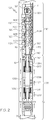
- the DWS pump 100 is placed within well piping 10 and includes a motor section 105, a pump section 110, a fluid inlet section 115 to accept a flow of incoming fluid 5, and a fluid outlet section 120 that can be used to discharge the fluid 5 to a riser, pipestack or related fluid-conveying tubing.
- both the motor section 105 and the pump section 110 may be made of modular subsections.
- pump section 110 there are numerous serially-arranged subsections in the form of pump bowls 112A, 112B, 112C and 112D that each house respective centrifugal impellers 110A, 110B, 110C and 110D.
- the fluid inlet section 115 is situated axially between the motor and pump sections 105, 110, and may include a mesh or related screen to keep large-scale particulate out in order to avoid or minimize particulate contact with the rotating components in the pump section 110.
- a seal 150 is used to keep the motor section 105 and the pump section 110 fluidly separate, as well as to reduce any pressure differentials that may exist between the motor section lubricant and the pump section lubricant.
- the temperature of the fluid 5 is typically between approximately 120° C and 160° C; however, even at that temperature, the water will remain in a liquid state due to the high surrounding pressure inherent in most geothermal sources. Moreover, because the operating temperature of the motor section is higher than that of the extracted fluid 5, any heat exchange between the flowing fluid 5 and the outer surfaces of motor section 105 tends to cool the motor section 105 and the various components within it.
- Motor section 105 has a casing, outer wall or related enclosure 105C that is preferably filled with oil or a related lubricant (not shown) that additionally possesses a high dielectric strength and thermally insulative properties to protect the various induction motor windings, as well as provide lubrication to the motor bearings.
- oil or a related lubricant (not shown) that additionally possesses a high dielectric strength and thermally insulative properties to protect the various induction motor windings, as well as provide lubrication to the motor bearings.
- the motor internal components are fluidly isolated from the pumped geothermal well water. Heat generated within the motor section 105 is efficiently carried by the internal oil to the enclosure 105C, where it can exchange heat with the water being pumped that passes over the outside of the enclosure 105C.
- the motor bearings (not shown) must be designed for such temperatures, with an operating lifetime of about 40,000 hours over about 250 motor start-ups.
- the predicted revolutions range of DWS pump 100 is between about 1,800 revolutions per minute and about 3,600 revolutions per minute.
- the lubricant used inside the enclosure 105C of the motor section 105 is fluidly isolated from the pump section 110. Thus, absent a complex piping scheme (not employed herein), the oil contained within the enclosure 105C of motor section 105 cannot be routed to other locations within the pump 100.
- another fluid 5 such as the well water being pumped, must be used to provide lubrication of the bearing assembly 200 (discussed below).
- This can lead to configurational simplicity in that the fluid being pumped from the deep well can serendipitously be used to perform the hydrodynamic function required by the bearing assembly 200. Nevertheless, such a configuration means there is a reduced opportunity to provide cooling to the bearing assembly 200 in the motor section 105, as well as to provide ample bearing lubrication during DWS pump 100 startup conditions.
- a shaft which includes a motor shaft section 125A and a pump shaft section 125B, extends over the length of DWS pump 100.
- the motor shaft section 125A extends out of the upper end of the motor section enclosure 105C, and is fluidly isolated between the motor and pump sections 105 and 110 by the aforementioned seals 150.
- Motor shaft section 125A is connected by a coupling 175 to pump shaft section 125B which is surrounded by and frictionally engages numerous bearings, including the radial bearing assembly 200 that is used to transmit normal loads (i.e., those perpendicular to the axial dimension of shafts 125A and 125B) from shaft eccentricities or the like to the remainder of the DWS pump 100, thereby reducing the impact of shaft wobbling on other components.
- the bearing assembly 200 as well as various other bearings (such as the ones housed in the pump section 110), are spaced along the length of shaft 125 at rotor dynamically advantageous locations. It will be understood by those skilled in the art that the number of radial bearings may vary according to the number of adjacently-joined shaft members, or other criteria.
- the present bearing assembly 200 is considered to be radial in nature because of its ability to carry radial (rather than thrust or related axial) loads, which are commonly transmitted through roller, tapered or related thrust-conveying mechanisms that are not discussed in further detail.
- Motor section 105 includes an induction motor (for example, a squirrel-cage motor) that includes a rotor 105A and a stator 105B that operates by induction motor and related electromagnetic principles well-known to those skilled in the art.
- stator 105B may further include coil winding 106 and a laminate plate assembly 107.
- motor section 105 may be made from numerous modular subsections (with corresponding rotors 105A and stators 105B) axially coupled to one another. Electric current is provided to stator 105B by a power cable 130 that typically extends along the outer surface defined by enclosure 105C.
- Power cable 130 is in turn electrically coupled to a source. Operation of motor section 105 causes the motor shaft section 125A and pump shaft section 125B of the shaft that is coupled to the rotor 105A to turn, which by virtue of the pump shaft section 125B connection to the one or more serially-arranged centrifugal impellers 110A, 110B, 110C and 110D in the pump section 110 turns them so that a fluid (such as the high temperature water resident in the geothermal source and shown presently as the serpentine line 5 in the upper right of the flow path of the pump section 110) can be pressurized and conveyed to the power plant 1 on the earth's surface.
- a check valve 120A can be situated in the fluid outlet section 120 that is fluidly connected to and downstream of the pump section 110.
- Flanged regions 140 are used to couple the various sections 105 and 110 together. Such flanged regions 140 may be secured together using bolted arrangement or some related method known to those skilled in the art.
- each of the motor section 105 and the pump section 110 of DWS pump 100 may be made up of numerous subsections, with such number dictated by the pumping requirements of the application. More particularly, within motor section 105 the number of stators 105B that can be made to cooperate with rotor or rotors 105A is commensurate with the power requirements of the DWS pump 100. In such a multiple stator configuration, each stator 105B within motor section 105 would have two radial bearing assemblies 200, arranged as substantial mirror images of one another on opposing axial ends of the stator 105B.
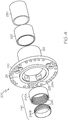
- Assembly 200 includes a housing 210 that can be matingly connected to an appropriate location on the motor section 105 of DWS pump 100.
- a flange 211 forms part of the housing 210 and includes numerous apertures 211A formed therein; some of the apertures 211A can be used in conjunction with bolts or related fasteners to establish a flanged and bolted relationship, while others can be used as backflow holes for any cooling fluid (not shown).
- Other larger versions 211B of the apertures are situated radially inward and can be used as a passageway for electrical wire and related power cables.
- the flanged relationship between adjacent housings 210 may be effected by connection to flanged region 140 that is depicted in FIG. 2 .
- the housing 210 also includes an axially-extending outer wall 212 that defines a generally smooth sleeve-like inner surface that is sized to form a tight fit (for example, a shrink fit or press-fit between the radial bearing housing 210 with a corresponding outer surface of a bushing 220 that together with a bearing sleeve 230 forms a part of radial bearing assembly 200 that transmits loads between the shaft 125 and the remainder of the DWS pump 100.
- the bearing sleeve 230 is sized to fit within the bushing 220 such that the outer surface of bearing sleeve 230 is in close cooperation with the inner surface of bushing 220. In this way, when assembled, the housing outer wall 212, the bushing 200 and the bearing sleeve 230 exhibit a nested or concentric relationship with one another.
- Lubricant is forced between the bearing sleeve 230 and bushing 220 by a dual screw pump 240 that is made up of a housing screw 240A and a shaft screw 240B.
- the lubricant being pumped is preferably oil contained within the motor section so that it is fluidly decoupled from the geothermal water being moved by DWS pump 100.
- the outer surface of shaft screw 240B and the inner surface of the housing screw 240A have continuous threads 245 formed on them. The threads 245 from each of the screws 240A, 240B mesh together upon assembly to define a positive-displacement screw conveyor with one or more lubricant pumping passages that pressurize an incoming fluid I (shown in FIG.
- Apertures 225 formed between flange 211 and the housing outer wall 212 provide a lubricant flow path that is used to feed lubricant from a lubricant supply (not shown) to the screw pump 240.
- the dual conveying screws 240A and 240B of the radial bearing assembly 200 take the lubricating fluid used in motor section 105 and compress it to ensure reliable and sufficient lubrication between the bearing sleeve 230 and the bushing 220. Specifically, screw 240B rotates while conveying screw 240A remains stationary. In this way, the radial bearing assembly 200 operates with a significant reduction in friction not only during operation of the DWS pump A 100 in high temperature environments, but also during the start-up and shut-down phases, thereby taking full advantage of their hydrodynamic properties. Further, the positioning of the dual conveying screws 240A and 240B in front of the bushing 220 and bearing sleeve 230 may increase the radial load capacity of the radial bearings.
- the radial bearing assembly 200 creates head due to the load and speed in the lubrication gap formed between the bearing sleeve 230 and the bushing 220. Because of the additional heat, the viscosity of the lubricating fluid drops, which causes a reduction in the lubrication film thickness and a concomitant decrease the load capacity. This can be compensated for by increasing the flow through the radial bearing assembly 200 , which acts to help the assembly stay cooler, which in turn results in a higher viscosity in the lubrication film. Also, it is contemplated that for operating the motor with a variable frequency drive, the bearings may be coated with a thin layer of an electrical insulation material having excellent mechanical properties on the fitting diameter.
- FIGS. 5A and 5B a cutaway view of the bushing 220 ( FIG. 5A ) and its multilayered construction ( FIG. 5B ) are shown.
- the innermost layer 220A i.e., the one which will engage the outer surface of the bearing sleeve 230
- the innermost layer 220A is made from a galvanized tin, preferably between about a couple of micrometers thick.
- a bronze layer 220B that is about 2 millimeters in thickness.
- a thicker steel housing (preferably 5 millimeters thick) 220C can be used, itself surrounded by an outermost layer 220D of an electrically insulative material, such as PEEK or a related structurally suitable polymeric.
- VFD variable frequency drive
- the thickness dimensions of the various layers of FIG. 5B are not necessarily shown to scale.
- the thickness of the innermost layer 220A may be (as indicated above) about three orders of magnitude thinner than the bronze layer 220B.
Landscapes
- Engineering & Computer Science (AREA)
- Mechanical Engineering (AREA)
- General Engineering & Computer Science (AREA)
- Physics & Mathematics (AREA)
- Fluid Mechanics (AREA)
- Structures Of Non-Positive Displacement Pumps (AREA)
- Sliding-Contact Bearings (AREA)
Claims (15)
- Induktionsmotor für eine geothermische Fluidpumpe zur Verwendung in einer Tauchpumpe für tiefe Bohrlöcher, umfassend:eine drehbare Welle (125);einen Rotor (105A) und einen Stator (105B), von denen einer eine mit der Welle (125) zusammenwirkende Induktionsspule umfasst, so dass bei Fließen von elektrischem Strom durch die Induktionsspule eine Drehbewegung auf die Welle (125) aufgebracht wird;eine Lageranordnung (200), umfassend:ein Lagergehäuse (210), das sich an dem Motorteil der Tauchpumpe für tiefe Bohrlöcher befestigen lässt und dazu ausgebildet ist, eine in der Welle (125) erzeugte Last auf eine Struktur innerhalb des Motors zu übertragen;ein innerhalb des Gehäuses (210) angeordnetes Gleitlager, wobei das Gleitlager dazu ausgebildet ist, in einer im Wesentlichen durchgängigen Schmierumgebung zu arbeiten, und das Folgendes umfasst:eine Mehrschichtbuchse (220), die an einer Innenfläche des Gehäuses (210) angeordnet ist; undeine Lagerhülse (230), die konzentrisch innerhalb der Mehrschichtbuchse (220) angeordnet ist und mit dieser zusammenwirkt, so dass die Hülse (230) relativ dazu in Reaktion auf die Drehung der Welle (125) dreht; undeinen Fluidtransportmechanismus, der innerhalb des Gehäuses angeordnet und dazu ausgebildet ist, ein Schmiermittel zwischen die Mehrschichtbuchse (220) und die Lagerhülse (230) zu fördern, so dass dazwischen ein Strömungsweg für das Schmiermittel als Teil der im Wesentlichen durchgängigen Schmierumgebung definiert wird;eine Motorteilummantelung (105C), die um die Welle (125), die Induktionsspule und die Lageranordnung (200) angeordnet ist, so dass das darin befindliche Schmiermittel als Wärmeentzugsmedium für die Lageranordnung (200) dienen kann;dadurch gekennzeichnet, dass der Induktionsmotor für eine geothermische Fluidpumpe weiterhin einen konzentrisch um die Motorteilummantelung (105C) gebildeten Durchgang für geothermisches Fluid umfasst, so dass bei thermischem Kontakt zwischen einem geothermischen Fluid in dem Durchgang und einer Außenfläche der Motorteilummantelung (105C) eine Wärmeübertragung von der Lageranordnung (200) zu dem geothermischen Fluid über die Motorteilummantelung (105C) stattfindet, während eine Fluidtrennung zwischen dem Schmiermittel und dem geothermischen Fluid beibehalten wird.
- Motor nach Anspruch 1, wobei die Mehrschichtbuchse (220) mindestens ein Metall und ein zweites Material umfasst, das zum Abdecken des mindestens einen Metalls verwendet wird.
- Motor nach Anspruch 2, wobei das zweite Material ein elektrisch nicht leitendes Material (220D) umfasst, das eine äußerste Schicht der Mehrschichtbuchse (220) bildet.
- Motor nach Anspruch 2, wobei das mindestens eine Metall mehrere Metallschichten umfasst.
- Motor nach Anspruch 4, wobei die die mehreren Metallschichten eine galvanisierte Zinnschicht (220A), eine Bronzeschicht (220B) und eine Stahlschicht (220C) umfassen.
- Motor nach Anspruch 1, wobei der Fluidtransportmechanismus ein an der Welle montierbares Schraubteil (240B) und ein im Gehäuse montiertes Schraubteil (240A) umfasst, die miteinander zusammenwirken, um dazwischen einen drehenden Pumpdurchgang für Schmiermittel zu definieren.
- Tauchpumpe für tiefe Bohrlöcher für ein geothermisches Fluid, umfassend einen Induktionsmotor für eine geothermische Fluidpumpe nach Anspruch 1, wobei die Pumpe Folgendes umfasst:einen Einlass (115) für geothermisches Fluid, mindestens ein drehbar mit der Welle (125) gekoppeltes Laufrad (110A, B, C, D); und einen Auslass (120) für geothermisches Fluid, wobei der Auslass (120) für geothermisches Fluid durch das mindestens eine Laufrad (110A, B, C, D) in Fluidverbindung mit dem Einlass (115) für geothermisches Fluid steht, so dass bei Drehung des mindestens einen Laufrads (110A, B, C, D) und Empfang von geothermischem Fluid von dem Einlass (115) für geothermisches Fluid das mindestens eine Laufrad (110A, B, C, D) das geothermische Fluid durch den Auslass (120) für geothermisches Fluid mit einer daraus resultierenden Druckzunahme fördert.
- Pumpe nach Anspruch 7, wobei die mindestens eine der Schichten der Buchse (220) eine Metallschicht umfasst.
- Pumpe nach Anspruch 8, wobei die mindestens eine Metallschicht eine auf der Innenfläche der Buchse (220) angeordnete galvanisierte Zinnschicht (220A), eine um die galvanisierte Zinnschicht (220A) angeordnete Bronzeschicht (220B) und die um die Bronzeschicht (220B) angeordnete Stahlschicht (220C) umfasst, und wobei sie wahlweise weiterhin eine auf der Außenfläche der Buchse (220) angeordnete Schicht aus elektrisch nicht leitendem Material (220D) umfasst.
- Pumpe nach Anspruch 7, weiterhin umfassend eine auf der Außenfläche der Buchse (220) angeordnete Schicht aus elektrisch nicht leitendem Material (220D)
- Verfahren zum Pumpen eines geothermischen Fluids, wobei das Verfahren Folgendes umfasst:Bringen einer Tauchpumpe für tiefe Bohrlöcher in Fluidverbindung mit einer Quelle von geothermischem Fluid, wobei die Pumpe Folgendes umfasst:einen Induktionsmotor für eine geothermische Fluidpumpe nach einem der Ansprüche 1 bis 6;einen Fluideinlass (115);mindestens ein Laufrad (110A, B, C, D), das über eine Welle (125) drehbar auf den Motor reagiert;einen Fluidauslass (120) in Fluidverbindung mit dem Fluideinlass (115) über das mindestens eine Laufrad (110A, B, C, D), so dass bei Drehung des mindestens einen Laufrads (110A, B, C, D) und Empfang von Fluid von dem Fluideinlass (115) das mindestens eine Laufrad (110A, B, C, D) das geothermische Fluid durch den Auslass (120) für geothermisches Fluid mit einer daraus resultierenden Druckzunahme fördert;mindestens eine mit der Welle (125) zusammenwirkende Lageranordnung (200), wobei die mindestens eine Lageranordnung (200) eine Lagerhülse (230) und eine Buchse (220) umfasst, die miteinander durch eine relative Drehbewegung zusammenwirken, um dazwischen einen Pumpenströmungsweg für das Schmiermittel zu definieren, wobei die Buchse (220) einen Mehrschichtaufbau aufweist, wobei mindestens eine der Schichten mindestens eine Metallschicht umfasst; undBetreiben der Pumpe derart, dass ein wesentlicher Anteil des geothermischen Fluids, das durch den Einlass (115) in die Pumpe eingebracht wird, durch den Auslass (120) abgegeben wird, dass weiterhin der Pumpenströmungsweg für das Schmiermittel bewirkt, dass ein Schmiermittel zwischen der Mehrschichtbuchse (220) und der Lagerhülse (230) strömt, um eine im Wesentlichen durchgängige Schmierung derselben während des Betriebs der Pumpe zu erhalten,wobei das Verfahren dadurch gekennzeichnet ist, dass ein Wärmeaustausch bei thermischem Kontakt zwischen einem geothermischen Fluid und der Lageranordnung (200) über eine um die Welle (125) und die Lageranordnung (200) angeordnete Motorteilummantelung (105C) ermöglicht wird.
- Verfahren nach Anspruch 11, wobei die Buchse (220) und die Lagerhülse (230) dazu ausgebildet sind, in einer im Wesentlichen durchgängigen Schmierumgebung mit mindestens 120 °C zu arbeiten.
- Verfahren nach Anspruch 11, wobei der Mehrschichtaufbau weiterhin mehrere Metallschichten umfasst, von denen mindestens eine aus einem Metall besteht, das dem der restlichen Schichten unähnlich ist.
- Verfahren nach Anspruch 13, wobei der Mehrschichtaufbau weiterhin eine nichtmetallische Schicht umfasst.
- Verfahren nach Anspruch 11, weiterhin umfassend einen an einem nicht drehbaren Teil der Lageranordnung (200) montierten ersten Pumpmechanismus (240A) und einen an der Welle (125) montierten zweiten Pumpmechanismus (240B), so dass bei Drehung der Welle (125) der erste und der zweite Pumpmechanismus zusammenwirken, um die Druckbeaufschlagung des Schmiermittels zu erreichen.
Applications Claiming Priority (2)
| Application Number | Priority Date | Filing Date | Title |
|---|---|---|---|
| US12/563,490 US8602753B2 (en) | 2009-09-21 | 2009-09-21 | Radial bearings for deep well submersible pumps |
| PCT/US2010/047603 WO2011034739A1 (en) | 2009-09-21 | 2010-09-02 | Radial bearings for deep well submersible pumps |
Publications (2)
| Publication Number | Publication Date |
|---|---|
| EP2480792A1 EP2480792A1 (de) | 2012-08-01 |
| EP2480792B1 true EP2480792B1 (de) | 2018-12-26 |
Family
ID=43334517
Family Applications (1)
| Application Number | Title | Priority Date | Filing Date |
|---|---|---|---|
| EP10752965.3A Active EP2480792B1 (de) | 2009-09-21 | 2010-09-02 | Radiallager für tauchpumpen für tiefe bohrlöcher |
Country Status (4)
| Country | Link |
|---|---|
| US (2) | US8602753B2 (de) |
| EP (1) | EP2480792B1 (de) |
| CA (1) | CA2774267C (de) |
| WO (1) | WO2011034739A1 (de) |
Families Citing this family (13)
| Publication number | Priority date | Publication date | Assignee | Title |
|---|---|---|---|---|
| US8800688B2 (en) * | 2011-07-20 | 2014-08-12 | Baker Hughes Incorporated | Downhole motors with a lubricating unit for lubricating the stator and rotor |
| US9212544B2 (en) * | 2012-02-08 | 2015-12-15 | Ormat Technologies Inc. | Apparatus and method for preventing damage to a downhole pump impeller |
| US9624938B2 (en) * | 2012-09-14 | 2017-04-18 | Baker Hughes Incorporated | Integrated motor bearing and rotor |
| US9617835B2 (en) * | 2013-03-15 | 2017-04-11 | Weatherford Technology Holdings, Llc | Barrier for a downhole tool |
| US9303648B2 (en) * | 2013-07-01 | 2016-04-05 | Baker Hughes Incorporated | Compliant radial bearing for electrical submersible pump |
| DE102015213420A1 (de) * | 2015-07-16 | 2017-03-30 | Continental Automotive Gmbh | Kraftstoffförderpumpe |
| US10767652B2 (en) * | 2015-12-14 | 2020-09-08 | Flowserve Management Company | Permanent magnet submersible motor with a one-piece rotor/yoke configuration and resin embedded magnets |
| US10240633B2 (en) | 2016-09-13 | 2019-03-26 | Baker Hughes, A Ge Company, Llc | Additively manufactured components for downhole operations |
| US20190186245A1 (en) * | 2017-12-20 | 2019-06-20 | Baker Hughes, A Ge Company, Llc | Lubricant Circulating Pump For Electrical Submersible Pump Motor |
| CA3092065A1 (en) * | 2018-02-23 | 2019-08-29 | Extract Management Company, Llc | Electric submersible pumping unit |
| US11578535B2 (en) | 2019-04-11 | 2023-02-14 | Upwing Energy, Inc. | Lubricating downhole-type rotating machines |
| US11174715B2 (en) * | 2019-06-10 | 2021-11-16 | Saudi Arabian Oil Company | Coupling enhanced oil recovery with energy requirements for crude production and processing |
| CN118602608B (zh) * | 2024-07-30 | 2025-07-11 | 西南石油大学 | 一种空心泵增强井内取热管外水循环取热系统装置 |
Citations (1)
| Publication number | Priority date | Publication date | Assignee | Title |
|---|---|---|---|---|
| EP0178087A1 (de) * | 1984-09-20 | 1986-04-16 | Framo Developments (U.K.) Limited | Kühlmittel für Tauchpumpenkopf |
Family Cites Families (20)
| Publication number | Priority date | Publication date | Assignee | Title |
|---|---|---|---|---|
| US2064086A (en) * | 1929-05-03 | 1936-12-15 | Gen Motors Corp | Bearing |
| GB546223A (en) | 1941-05-05 | 1942-07-02 | Hayward Tyler & Co Ltd | Improvements in or relating to submersible pumps |
| GB580128A (en) | 1944-04-26 | 1946-08-28 | C H Johnson And Sons Ltd | Improvements in and relating to centrifugal pumps |
| US2592612A (en) * | 1947-08-02 | 1952-04-15 | Cleveland Steel Products Corp | Rotary fuel feeder for flame ring burners |
| DE1269843B (de) | 1964-06-09 | 1968-06-06 | Yuichiro Furukawa | Druckfluessigkeitsgeschmierte Gleitlageranordnung fuer Radwellen |
| GB1360489A (en) * | 1971-06-03 | 1974-07-17 | Weir Pumps Ltd | Sealed lubricating system module |
| US4507925A (en) * | 1981-05-07 | 1985-04-02 | Schaetzle Walter J | Method for and thermal energy injection withdrawal system for aquifers |
| US4620804A (en) * | 1985-05-15 | 1986-11-04 | Goyne Thomas S | Bearing and grease seal structure |
| US4913239A (en) * | 1989-05-26 | 1990-04-03 | Otis Engineering Corporation | Submersible well pump and well completion system |
| US5713670A (en) * | 1995-08-30 | 1998-02-03 | International Business Machines Corporation | Self pressurizing journal bearing assembly |
| EP0791760A3 (de) * | 1996-02-20 | 1997-09-10 | Ebara Corporation | Wassergeschmiertes Lager oder Dichtung |
| AT412664B (de) | 1998-04-27 | 2005-05-25 | Andritz Ag Maschf | Lagerung für eine pumpe, insbesondere hauptkühlmittelpumpe |
| DE10058499A1 (de) * | 2000-11-24 | 2002-05-29 | Ksb Ag | Gleitlager für eine Kreiselpumpe |
| KR100899468B1 (ko) * | 2007-02-23 | 2009-05-27 | 가부시끼가이샤 도시바 | 리니어 액츄에이터 및 리니어 액츄에이터를 이용한 부품보유 지지 장치, 다이 본더 장치 |
| US8113765B2 (en) * | 2007-12-27 | 2012-02-14 | Ormat Technologies Inc. | Water lubricated line shaft bearing and lubrication system for a geothermal pump |
| US8696334B2 (en) * | 2008-04-29 | 2014-04-15 | Chevron U.S.A. Inc. | Submersible pumping system with heat transfer mechanism |
| WO2009135069A1 (en) * | 2008-04-30 | 2009-11-05 | Altarock Energy, Inc. | Method and cooling system for electric submersible pumps/motors for use in geothermal wells |
| DE112010001474T5 (de) * | 2009-03-31 | 2012-07-05 | Baker Hughes Inc. | Verbesserte Wärmeübertragung durch einen elektrischen Tauchpumpenmotor |
| US8740586B2 (en) * | 2009-06-29 | 2014-06-03 | Baker Hughes Incorporated | Heat exchanger for ESP motor |
| US20120089103A1 (en) * | 2010-10-07 | 2012-04-12 | Ruben Tel-Ari | Medical Device For Healing Wounds and Skin Diseases |
-
2009
- 2009-09-21 US US12/563,490 patent/US8602753B2/en active Active
-
2010
- 2010-09-02 CA CA2774267A patent/CA2774267C/en active Active
- 2010-09-02 WO PCT/US2010/047603 patent/WO2011034739A1/en not_active Ceased
- 2010-09-02 EP EP10752965.3A patent/EP2480792B1/de active Active
-
2013
- 2013-10-30 US US14/066,840 patent/US9011115B2/en active Active
Patent Citations (1)
| Publication number | Priority date | Publication date | Assignee | Title |
|---|---|---|---|---|
| EP0178087A1 (de) * | 1984-09-20 | 1986-04-16 | Framo Developments (U.K.) Limited | Kühlmittel für Tauchpumpenkopf |
Also Published As
| Publication number | Publication date |
|---|---|
| US20110070099A1 (en) | 2011-03-24 |
| US20140050594A1 (en) | 2014-02-20 |
| CA2774267A1 (en) | 2011-03-24 |
| EP2480792A1 (de) | 2012-08-01 |
| US8602753B2 (en) | 2013-12-10 |
| WO2011034739A1 (en) | 2011-03-24 |
| US9011115B2 (en) | 2015-04-21 |
| CA2774267C (en) | 2018-02-13 |
Similar Documents
| Publication | Publication Date | Title |
|---|---|---|
| EP2480792B1 (de) | Radiallager für tauchpumpen für tiefe bohrlöcher | |
| EP3527830B1 (de) | System zum bewegen von fluid mit entgegengesetzten axialkräften | |
| EP2539994B1 (de) | Kühlsystem für einen mehrstufigen elektromotor | |
| CA2721015C (en) | Underwater delivery unit | |
| CA2934477C (en) | Multistage centrifugal pump with integral abrasion-resistant axial thrust bearings | |
| CA3114640C (en) | Active and passive refrigeration systems for downhole motors | |
| RU2686971C2 (ru) | Оптимизированное охлаждение электродвигателя при насосно-компрессорной добыче | |
| US11133721B2 (en) | Electromagnetic coupling for ESP motor | |
| RU2394172C1 (ru) | Компрессорный блок и применение охлаждающей среды | |
| CA2137606A1 (en) | High speed fluid pump powered by an integral canned electrical motor | |
| CA2960471C (en) | INTERNAL OIL CIRCULATION REFRIGERATION SYSTEM | |
| WO2009090479A2 (en) | Water lubricated line shaft bearing and lubrication system for a geothermal pump | |
| US11098727B2 (en) | Counter rotating back-to-back fluid movement system | |
| CN210317773U (zh) | 一种用于铅铋反应堆一回路的立式离心泵 | |
| JP2006009740A (ja) | 水中モータポンプ | |
| RU2384743C1 (ru) | Центробежный моноблочный электронасос для перекачки агрессивных жидкостей | |
| CA3009519C (en) | Electromagnetic coupling for esp motor | |
| Kinnear | HIGH RELIABILITY MULTISTAGE h4INE DEWATERING PUMPSETS | |
| Strecker | Achieving space and cost savings with advanced bearing technology |
Legal Events
| Date | Code | Title | Description |
|---|---|---|---|
| PUAI | Public reference made under article 153(3) epc to a published international application that has entered the european phase |
Free format text: ORIGINAL CODE: 0009012 |
|
| 17P | Request for examination filed |
Effective date: 20120418 |
|
| AK | Designated contracting states |
Kind code of ref document: A1 Designated state(s): AL AT BE BG CH CY CZ DE DK EE ES FI FR GB GR HR HU IE IS IT LI LT LU LV MC MK MT NL NO PL PT RO SE SI SK SM TR |
|
| DAX | Request for extension of the european patent (deleted) | ||
| STAA | Information on the status of an ep patent application or granted ep patent |
Free format text: STATUS: EXAMINATION IS IN PROGRESS |
|
| 17Q | First examination report despatched |
Effective date: 20161219 |
|
| GRAP | Despatch of communication of intention to grant a patent |
Free format text: ORIGINAL CODE: EPIDOSNIGR1 |
|
| STAA | Information on the status of an ep patent application or granted ep patent |
Free format text: STATUS: GRANT OF PATENT IS INTENDED |
|
| INTG | Intention to grant announced |
Effective date: 20180712 |
|
| GRAS | Grant fee paid |
Free format text: ORIGINAL CODE: EPIDOSNIGR3 |
|
| GRAA | (expected) grant |
Free format text: ORIGINAL CODE: 0009210 |
|
| STAA | Information on the status of an ep patent application or granted ep patent |
Free format text: STATUS: THE PATENT HAS BEEN GRANTED |
|
| AK | Designated contracting states |
Kind code of ref document: B1 Designated state(s): AL AT BE BG CH CY CZ DE DK EE ES FI FR GB GR HR HU IE IS IT LI LT LU LV MC MK MT NL NO PL PT RO SE SI SK SM TR |
|
| REG | Reference to a national code |
Ref country code: GB Ref legal event code: FG4D |
|
| REG | Reference to a national code |
Ref country code: CH Ref legal event code: EP |
|
| REG | Reference to a national code |
Ref country code: AT Ref legal event code: REF Ref document number: 1081812 Country of ref document: AT Kind code of ref document: T Effective date: 20190115 |
|
| REG | Reference to a national code |
Ref country code: DE Ref legal event code: R096 Ref document number: 602010056064 Country of ref document: DE |
|
| REG | Reference to a national code |
Ref country code: IE Ref legal event code: FG4D |
|
| REG | Reference to a national code |
Ref country code: CH Ref legal event code: NV Representative=s name: TR-IP CONSULTING LLC, CH |
|
| PG25 | Lapsed in a contracting state [announced via postgrant information from national office to epo] |
Ref country code: BG Free format text: LAPSE BECAUSE OF FAILURE TO SUBMIT A TRANSLATION OF THE DESCRIPTION OR TO PAY THE FEE WITHIN THE PRESCRIBED TIME-LIMIT Effective date: 20190326 Ref country code: NO Free format text: LAPSE BECAUSE OF FAILURE TO SUBMIT A TRANSLATION OF THE DESCRIPTION OR TO PAY THE FEE WITHIN THE PRESCRIBED TIME-LIMIT Effective date: 20190326 Ref country code: FI Free format text: LAPSE BECAUSE OF FAILURE TO SUBMIT A TRANSLATION OF THE DESCRIPTION OR TO PAY THE FEE WITHIN THE PRESCRIBED TIME-LIMIT Effective date: 20181226 Ref country code: LT Free format text: LAPSE BECAUSE OF FAILURE TO SUBMIT A TRANSLATION OF THE DESCRIPTION OR TO PAY THE FEE WITHIN THE PRESCRIBED TIME-LIMIT Effective date: 20181226 Ref country code: LV Free format text: LAPSE BECAUSE OF FAILURE TO SUBMIT A TRANSLATION OF THE DESCRIPTION OR TO PAY THE FEE WITHIN THE PRESCRIBED TIME-LIMIT Effective date: 20181226 Ref country code: HR Free format text: LAPSE BECAUSE OF FAILURE TO SUBMIT A TRANSLATION OF THE DESCRIPTION OR TO PAY THE FEE WITHIN THE PRESCRIBED TIME-LIMIT Effective date: 20181226 |
|
| REG | Reference to a national code |
Ref country code: NL Ref legal event code: MP Effective date: 20181226 |
|
| REG | Reference to a national code |
Ref country code: LT Ref legal event code: MG4D |
|
| PG25 | Lapsed in a contracting state [announced via postgrant information from national office to epo] |
Ref country code: AL Free format text: LAPSE BECAUSE OF FAILURE TO SUBMIT A TRANSLATION OF THE DESCRIPTION OR TO PAY THE FEE WITHIN THE PRESCRIBED TIME-LIMIT Effective date: 20181226 Ref country code: SE Free format text: LAPSE BECAUSE OF FAILURE TO SUBMIT A TRANSLATION OF THE DESCRIPTION OR TO PAY THE FEE WITHIN THE PRESCRIBED TIME-LIMIT Effective date: 20181226 Ref country code: GR Free format text: LAPSE BECAUSE OF FAILURE TO SUBMIT A TRANSLATION OF THE DESCRIPTION OR TO PAY THE FEE WITHIN THE PRESCRIBED TIME-LIMIT Effective date: 20190327 |
|
| REG | Reference to a national code |
Ref country code: AT Ref legal event code: MK05 Ref document number: 1081812 Country of ref document: AT Kind code of ref document: T Effective date: 20181226 |
|
| PG25 | Lapsed in a contracting state [announced via postgrant information from national office to epo] |
Ref country code: NL Free format text: LAPSE BECAUSE OF FAILURE TO SUBMIT A TRANSLATION OF THE DESCRIPTION OR TO PAY THE FEE WITHIN THE PRESCRIBED TIME-LIMIT Effective date: 20181226 |
|
| PG25 | Lapsed in a contracting state [announced via postgrant information from national office to epo] |
Ref country code: PL Free format text: LAPSE BECAUSE OF FAILURE TO SUBMIT A TRANSLATION OF THE DESCRIPTION OR TO PAY THE FEE WITHIN THE PRESCRIBED TIME-LIMIT Effective date: 20181226 Ref country code: PT Free format text: LAPSE BECAUSE OF FAILURE TO SUBMIT A TRANSLATION OF THE DESCRIPTION OR TO PAY THE FEE WITHIN THE PRESCRIBED TIME-LIMIT Effective date: 20190426 Ref country code: ES Free format text: LAPSE BECAUSE OF FAILURE TO SUBMIT A TRANSLATION OF THE DESCRIPTION OR TO PAY THE FEE WITHIN THE PRESCRIBED TIME-LIMIT Effective date: 20181226 Ref country code: CZ Free format text: LAPSE BECAUSE OF FAILURE TO SUBMIT A TRANSLATION OF THE DESCRIPTION OR TO PAY THE FEE WITHIN THE PRESCRIBED TIME-LIMIT Effective date: 20181226 |
|
| PG25 | Lapsed in a contracting state [announced via postgrant information from national office to epo] |
Ref country code: RO Free format text: LAPSE BECAUSE OF FAILURE TO SUBMIT A TRANSLATION OF THE DESCRIPTION OR TO PAY THE FEE WITHIN THE PRESCRIBED TIME-LIMIT Effective date: 20181226 Ref country code: EE Free format text: LAPSE BECAUSE OF FAILURE TO SUBMIT A TRANSLATION OF THE DESCRIPTION OR TO PAY THE FEE WITHIN THE PRESCRIBED TIME-LIMIT Effective date: 20181226 Ref country code: IS Free format text: LAPSE BECAUSE OF FAILURE TO SUBMIT A TRANSLATION OF THE DESCRIPTION OR TO PAY THE FEE WITHIN THE PRESCRIBED TIME-LIMIT Effective date: 20190426 Ref country code: SM Free format text: LAPSE BECAUSE OF FAILURE TO SUBMIT A TRANSLATION OF THE DESCRIPTION OR TO PAY THE FEE WITHIN THE PRESCRIBED TIME-LIMIT Effective date: 20181226 Ref country code: SK Free format text: LAPSE BECAUSE OF FAILURE TO SUBMIT A TRANSLATION OF THE DESCRIPTION OR TO PAY THE FEE WITHIN THE PRESCRIBED TIME-LIMIT Effective date: 20181226 |
|
| REG | Reference to a national code |
Ref country code: DE Ref legal event code: R097 Ref document number: 602010056064 Country of ref document: DE |
|
| PG25 | Lapsed in a contracting state [announced via postgrant information from national office to epo] |
Ref country code: AT Free format text: LAPSE BECAUSE OF FAILURE TO SUBMIT A TRANSLATION OF THE DESCRIPTION OR TO PAY THE FEE WITHIN THE PRESCRIBED TIME-LIMIT Effective date: 20181226 Ref country code: DK Free format text: LAPSE BECAUSE OF FAILURE TO SUBMIT A TRANSLATION OF THE DESCRIPTION OR TO PAY THE FEE WITHIN THE PRESCRIBED TIME-LIMIT Effective date: 20181226 |
|
| PLBE | No opposition filed within time limit |
Free format text: ORIGINAL CODE: 0009261 |
|
| STAA | Information on the status of an ep patent application or granted ep patent |
Free format text: STATUS: NO OPPOSITION FILED WITHIN TIME LIMIT |
|
| 26N | No opposition filed |
Effective date: 20190927 |
|
| REG | Reference to a national code |
Ref country code: CH Ref legal event code: PCAR Free format text: NEW ADDRESS: ROUTE DU COUTSET 18, 1485 NUVILLY (CH) |
|
| PG25 | Lapsed in a contracting state [announced via postgrant information from national office to epo] |
Ref country code: SI Free format text: LAPSE BECAUSE OF FAILURE TO SUBMIT A TRANSLATION OF THE DESCRIPTION OR TO PAY THE FEE WITHIN THE PRESCRIBED TIME-LIMIT Effective date: 20181226 |
|
| PG25 | Lapsed in a contracting state [announced via postgrant information from national office to epo] |
Ref country code: TR Free format text: LAPSE BECAUSE OF FAILURE TO SUBMIT A TRANSLATION OF THE DESCRIPTION OR TO PAY THE FEE WITHIN THE PRESCRIBED TIME-LIMIT Effective date: 20181226 |
|
| PG25 | Lapsed in a contracting state [announced via postgrant information from national office to epo] |
Ref country code: MC Free format text: LAPSE BECAUSE OF FAILURE TO SUBMIT A TRANSLATION OF THE DESCRIPTION OR TO PAY THE FEE WITHIN THE PRESCRIBED TIME-LIMIT Effective date: 20181226 |
|
| PG25 | Lapsed in a contracting state [announced via postgrant information from national office to epo] |
Ref country code: LU Free format text: LAPSE BECAUSE OF NON-PAYMENT OF DUE FEES Effective date: 20190902 Ref country code: IE Free format text: LAPSE BECAUSE OF NON-PAYMENT OF DUE FEES Effective date: 20190902 |
|
| REG | Reference to a national code |
Ref country code: BE Ref legal event code: MM Effective date: 20190930 |
|
| PG25 | Lapsed in a contracting state [announced via postgrant information from national office to epo] |
Ref country code: BE Free format text: LAPSE BECAUSE OF NON-PAYMENT OF DUE FEES Effective date: 20190930 |
|
| PG25 | Lapsed in a contracting state [announced via postgrant information from national office to epo] |
Ref country code: CY Free format text: LAPSE BECAUSE OF FAILURE TO SUBMIT A TRANSLATION OF THE DESCRIPTION OR TO PAY THE FEE WITHIN THE PRESCRIBED TIME-LIMIT Effective date: 20181226 |
|
| PG25 | Lapsed in a contracting state [announced via postgrant information from national office to epo] |
Ref country code: MT Free format text: LAPSE BECAUSE OF FAILURE TO SUBMIT A TRANSLATION OF THE DESCRIPTION OR TO PAY THE FEE WITHIN THE PRESCRIBED TIME-LIMIT Effective date: 20181226 Ref country code: HU Free format text: LAPSE BECAUSE OF FAILURE TO SUBMIT A TRANSLATION OF THE DESCRIPTION OR TO PAY THE FEE WITHIN THE PRESCRIBED TIME-LIMIT; INVALID AB INITIO Effective date: 20100902 |
|
| PG25 | Lapsed in a contracting state [announced via postgrant information from national office to epo] |
Ref country code: MK Free format text: LAPSE BECAUSE OF FAILURE TO SUBMIT A TRANSLATION OF THE DESCRIPTION OR TO PAY THE FEE WITHIN THE PRESCRIBED TIME-LIMIT Effective date: 20181226 |
|
| P01 | Opt-out of the competence of the unified patent court (upc) registered |
Effective date: 20230526 |
|
| REG | Reference to a national code |
Ref country code: CH Ref legal event code: U11 Free format text: ST27 STATUS EVENT CODE: U-0-0-U10-U11 (AS PROVIDED BY THE NATIONAL OFFICE) Effective date: 20251001 |
|
| PGFP | Annual fee paid to national office [announced via postgrant information from national office to epo] |
Ref country code: DE Payment date: 20250929 Year of fee payment: 16 |
|
| PGFP | Annual fee paid to national office [announced via postgrant information from national office to epo] |
Ref country code: IT Payment date: 20250919 Year of fee payment: 16 |
|
| PGFP | Annual fee paid to national office [announced via postgrant information from national office to epo] |
Ref country code: GB Payment date: 20250929 Year of fee payment: 16 |
|
| PGFP | Annual fee paid to national office [announced via postgrant information from national office to epo] |
Ref country code: FR Payment date: 20250925 Year of fee payment: 16 |
|
| PGFP | Annual fee paid to national office [announced via postgrant information from national office to epo] |
Ref country code: CH Payment date: 20251001 Year of fee payment: 16 |