EP2480470B1 - Optical checking method for evaluating quality in print processing - Google Patents
Optical checking method for evaluating quality in print processing Download PDFInfo
- Publication number
- EP2480470B1 EP2480470B1 EP10755144.2A EP10755144A EP2480470B1 EP 2480470 B1 EP2480470 B1 EP 2480470B1 EP 10755144 A EP10755144 A EP 10755144A EP 2480470 B1 EP2480470 B1 EP 2480470B1
- Authority
- EP
- European Patent Office
- Prior art keywords
- mirror
- product
- profile
- line
- beam profile
- Prior art date
- Legal status (The legal status is an assumption and is not a legal conclusion. Google has not performed a legal analysis and makes no representation as to the accuracy of the status listed.)
- Not-in-force
Links
Images


Classifications
-
- B—PERFORMING OPERATIONS; TRANSPORTING
- B65—CONVEYING; PACKING; STORING; HANDLING THIN OR FILAMENTARY MATERIAL
- B65H—HANDLING THIN OR FILAMENTARY MATERIAL, e.g. SHEETS, WEBS, CABLES
- B65H7/00—Controlling article feeding, separating, pile-advancing, or associated apparatus, to take account of incorrect feeding, absence of articles, or presence of faulty articles
- B65H7/02—Controlling article feeding, separating, pile-advancing, or associated apparatus, to take account of incorrect feeding, absence of articles, or presence of faulty articles by feelers or detectors
- B65H7/06—Controlling article feeding, separating, pile-advancing, or associated apparatus, to take account of incorrect feeding, absence of articles, or presence of faulty articles by feelers or detectors responsive to presence of faulty articles or incorrect separation or feed
-
- B—PERFORMING OPERATIONS; TRANSPORTING
- B65—CONVEYING; PACKING; STORING; HANDLING THIN OR FILAMENTARY MATERIAL
- B65H—HANDLING THIN OR FILAMENTARY MATERIAL, e.g. SHEETS, WEBS, CABLES
- B65H29/00—Delivering or advancing articles from machines; Advancing articles to or into piles
- B65H29/003—Delivering or advancing articles from machines; Advancing articles to or into piles by grippers
-
- B—PERFORMING OPERATIONS; TRANSPORTING
- B65—CONVEYING; PACKING; STORING; HANDLING THIN OR FILAMENTARY MATERIAL
- B65H—HANDLING THIN OR FILAMENTARY MATERIAL, e.g. SHEETS, WEBS, CABLES
- B65H43/00—Use of control, checking, or safety devices, e.g. automatic devices comprising an element for sensing a variable
- B65H43/04—Use of control, checking, or safety devices, e.g. automatic devices comprising an element for sensing a variable detecting, or responding to, presence of faulty articles
-
- B—PERFORMING OPERATIONS; TRANSPORTING
- B65—CONVEYING; PACKING; STORING; HANDLING THIN OR FILAMENTARY MATERIAL
- B65H—HANDLING THIN OR FILAMENTARY MATERIAL, e.g. SHEETS, WEBS, CABLES
- B65H5/00—Feeding articles separated from piles; Feeding articles to machines
- B65H5/08—Feeding articles separated from piles; Feeding articles to machines by grippers, e.g. suction grippers
- B65H5/085—Feeding articles separated from piles; Feeding articles to machines by grippers, e.g. suction grippers by combinations of endless conveyors and grippers
-
- B—PERFORMING OPERATIONS; TRANSPORTING
- B65—CONVEYING; PACKING; STORING; HANDLING THIN OR FILAMENTARY MATERIAL
- B65H—HANDLING THIN OR FILAMENTARY MATERIAL, e.g. SHEETS, WEBS, CABLES
- B65H2301/00—Handling processes for sheets or webs
- B65H2301/30—Orientation, displacement, position of the handled material
- B65H2301/32—Orientation of handled material
- B65H2301/323—Hanging
-
- B—PERFORMING OPERATIONS; TRANSPORTING
- B65—CONVEYING; PACKING; STORING; HANDLING THIN OR FILAMENTARY MATERIAL
- B65H—HANDLING THIN OR FILAMENTARY MATERIAL, e.g. SHEETS, WEBS, CABLES
- B65H2511/00—Dimensions; Position; Numbers; Identification; Occurrences
- B65H2511/40—Identification
-
- B—PERFORMING OPERATIONS; TRANSPORTING
- B65—CONVEYING; PACKING; STORING; HANDLING THIN OR FILAMENTARY MATERIAL
- B65H—HANDLING THIN OR FILAMENTARY MATERIAL, e.g. SHEETS, WEBS, CABLES
- B65H2515/00—Physical entities not provided for in groups B65H2511/00 or B65H2513/00
- B65H2515/84—Quality; Condition, e.g. degree of wear
-
- B—PERFORMING OPERATIONS; TRANSPORTING
- B65—CONVEYING; PACKING; STORING; HANDLING THIN OR FILAMENTARY MATERIAL
- B65H—HANDLING THIN OR FILAMENTARY MATERIAL, e.g. SHEETS, WEBS, CABLES
- B65H2553/00—Sensing or detecting means
- B65H2553/40—Sensing or detecting means using optical, e.g. photographic, elements
- B65H2553/42—Cameras
Landscapes
- Engineering & Computer Science (AREA)
- Mechanical Engineering (AREA)
- Length Measuring Devices By Optical Means (AREA)
- Investigating Materials By The Use Of Optical Means Adapted For Particular Applications (AREA)
Description
Die vorliegende Erfindung betrifft ein optisches Kontrollverfahren zur Qualitätsbeurteilung in der Druckweiterverarbeitung gemäss Oberbegriff von Patentanspruch 1 und eine Vorrichtung zur Durchführung des Verfahrens gemäss Oberbegriff von Patentanspruch 4.The present invention relates to an optical control method for quality assessment in the print finishing according to the preamble of
Optische Kontrollverfahren zum Zählen und Erkennen von flexiblen, flächigen Produkten, insbesondere Druckprodukten wie Zeitungen, Zeitschriften oder Teilen davon, in der Druckweiterverarbeitung sind grundsätzlich bekannt.Optical control methods for counting and detecting flexible, sheet-like products, in particular printed products such as newspapers, magazines or parts thereof, in the print finishing are basically known.
Aus der
Der optische Sensor, in einer bevorzugten Ausführungsform beispielsweise eine elektronische Kamera mit einer Mehrzahl von lichtempfindlichen Elementen, ist mit einer Detektionsoptik zur Formung eines Detektionsstrahlprofils ausgestattet. Als Detektionsoptik wird beispielsweise ein Kameraobjektiv eingesetzt. Das Detektionsstrahlprofil umfasst all die Orte, von denen der optische Sensor Licht detektieren kann. Bei Verwendung eines optischen Sensors mit mehreren lichtempfindlichen Elementen, wie bei der bereits erwähnten Kamera, setzt sich das Detektionsstrahlprofil des optischen Sensors aus den jedem einzelnen lichtempfindlichen Element zugeordneten einzelnen Detektionsstrahlprofilen zusammen. Das Detektionsstrahlprofil des optischen Sensors könnte beispielsweise sichtbar gemacht werden, in dem die lichtempfindlichen Elemente durch kleine Lichtquellen ersetzt werden würden. In Analogie zur Lichtquelle kann auch dem optischen Sensor über die Detektionsoptik eine optische Achse zugeordnet werden. Diese optische Achse bildet im Sinne der
Das Beleuchtungsstrahlprofil und das Detektionsstrahlprofil sind dabei derart winkelversetzt zueinander ausgerichtet, dass sie in einem Detektionsbereich überlappend wirken. In einer bevorzugten Ausführungsform liegen die Beleuchtungsstrahlachse und die Detektionsstrahlachse sogar in einer Ebene. Zum Zählen der flächigen Produkte muss sich wenigstens ein Abschnitt des Oberflächenprofils der flächigen Produkte im Detektionsbereich befinden. Dieser Abschnitt ist erfindungsgemäss wenigstens teilweise durch das Beleuchtungsstrahlprofil begrenzt und mittels des optischen Sensors detektierbar. Der optische Sensor kann ein Detektionssignal mit Informationen über den detektierten Abschnitt des Oberflächenprofils erzeugen. Das Detektionssignal wird an eine nachgeschaltete Auswerteeinheit weitergeleitet. Die Auswerteeinheit, vorzugsweise ein Computer, kann aus dem Detektionssignal die Anzahl der flächigen Produkte, die sich zum Zeitpunkt der Detektion im Detektionsbereich befunden haben, bestimmen.In this case, the illumination beam profile and the detection beam profile are oriented at an angle to one another in such a way that they act in an overlapping manner in a detection area. In a preferred embodiment, the illumination beam axis and the detection beam axis are even in one plane. For counting the sheet-like products, at least a portion of the surface profile of the sheet-like products must be in the detection area. This section is according to the invention at least partially limited by the illumination beam profile and detectable by means of the optical sensor. The optical sensor may generate a detection signal with information about the detected portion of the surface profile. The detection signal is forwarded to a downstream evaluation unit. The evaluation unit, preferably a computer, can use the detection signal to determine the number of areal products which were located in the detection area at the time of detection.
In einer besonders bevorzugten Ausführungsform ist der Vorrichtung zum Zählen und Erkennen von flächigen Produkten eine Transportvorrichtung zugeordnet. Die mit Hilfe der Transportvorrichtung entlang einer Transportrichtung durch den Detektionsbereich bewegten flächige Produkte werden vorzugsweise fortlaufend gezählt, um beispielsweise deren Vollständigkeit zu kontrollieren. Die Beleuchtungsstrahlachse ist dabei bevorzugter Weise gegenüber den Flächennormalen der beispielsweise auf einem Förderband aufliegenden oder mittels Klammern oder Greifern transportierten flächigen Produkte geneigt ausgerichtet. Das Beleuchtungsstrahlprofil im Detektionsbereich ist mittels der Strahlformungsoptik vorzugsweise als ein im Wesentlichen geradliniger Bereich, insbesondere als eine sogenannte Beleuchtungslinie, ausgeformt, welche den Abschnitt des Oberflächenprofils der flächigen Produkte auf eine definierte Weise beleuchtet. Vorzugsweise erstreckt sich die Beleuchtungslinie im Wesentlichen parallel zur Transportrichtung. Unmittelbar oberhalb von den flächigen Produkten, mit seiner Detektionsstrahlachse leicht geneigt zu deren Flächennormalen und im Wesentlichen rechtwinklig zur Transportrichtung ausgerichtet, befindet sich eine Kamera als optischer Sensor. Das Detektionsstrahlprofil ist durch die Detektionsoptik derart ausgeformt, dass eine Abbildung von der durch die Lichtquelle auf die Oberfläche der flächigen Produkte projizierten Beleuchtungslinie auf den lichtempfindlichen Elementen der Kamera erzeugt wird.In a particularly preferred embodiment, the apparatus for counting and detecting sheet-like products is assigned a transport device. The flat products which are moved through the detection area along a transport direction by means of the transport device are preferably continuously counted in order, for example, to check their completeness. The illumination beam axis is preferably aligned inclined relative to the surface normal of, for example, resting on a conveyor belt or transported by means of brackets or grippers flat products. The illumination beam profile in the detection area is preferably formed by means of the beam shaping optics as a substantially rectilinear region, in particular as a so-called illumination line, which illuminates the section of the surface profile of the planar products in a defined manner. Preferably, the illumination line extends substantially parallel to the transport direction. Immediately above the sheet-like products, with its detection beam axis slightly inclined to the surface normal and aligned substantially perpendicular to the transport direction, there is a camera as an optical sensor. The detection beam profile is formed by the detection optics such that an image of the light line projected onto the surface of the planar products by the light source is generated on the photosensitive elements of the camera.
Aufgrund der durch die Dicke und die Anordnung der flächigen Produkte hervorgerufenen Höhenunterschiede im "abzutastenden" Oberflächenprofil, insbesondere dann, wenn sich ein Randbereich eines flächigen Produkts im Detektionsbereich befindet, wird ein von der Kamera aufgenommenes Bild von der auf diese unebene "Projektionsfläche" projizierten Beleuchtungslinie deren Krümmungen und Absätze wiedergeben. Diese Bildinformationen werden im Detektionssignal an einen elektrisch verbundenen Computer weitergeleitet. Ein auf dem Computer ausführbares Bildverarbeitungsprogramm kann dann aus dem Abbild der projizierten Beleuchtungslinie anhand der Krümmungen und Absätze die Anzahl der flächigen Produkte, die sich im Detektionsbereich befunden haben, ermitteln. Damit die Bildinformationen möglichst wenig durch Bewegungsartefakte aufgrund des Transports der flächigen Produkte während der Bildaufnahme beeinflusst werden, ist die Aufnahme bzw. Detektionszeit kurz im Vergleich zur Zeit, innerhalb der sich ein flächiges Produkt um den Betrag seiner Dicke bewegt hat. Die Anzahl der sich im Detektionsbereich befindlichen flächigen Produkte wird allein aus dem detektierten Oberflächenprofil der flächigen Produkte bestimmt. Es ist nicht nötig, Identifikationsinformationen an den flächigen Produkten anzubringen. Aufgrund der gegenüber dem Umgebungslicht vergleichsweise hohen Intensität des von der Lichtquelle erzeugten Lichts im Beleuchtungsstrahlprofil, insbesondere innerhalb der Beleuchtungslinie im Detektionsbereich, ergibt sich ein ausreichender Kontrast in den Bildaufnahmen, so dass eine zuverlässige Identifizierung des angestrahlten Oberflächenprofils gewährleistet ist. Bei Verwendung einer im Wesentlichen monochromatischen Lichtquelle, beispielsweise eines Lasers, kann der optische Sensor zudem mit entsprechenden Filterelementen ausgestattet sein, um den Störeinfluss von Umgebungslicht zusätzlich zu verringern.Due to the height differences caused by the thickness and the arrangement of the sheet-like products in the "surface profile to be scanned", in particular when an edge region of a flat product is in the detection region, an image recorded by the camera is projected from the illumination line projected onto this uneven "projection surface" whose bends and heels reflect. This image information is forwarded in the detection signal to an electrically connected computer. A computer-executable image processing program can then determine from the image of the projected illumination line on the basis of the curvatures and paragraphs the number of planar products that have been in the detection area. So the picture information As little as possible are affected by motion artifacts due to the transport of the sheet-like products during image acquisition, the recording or detection time is short compared to the time within which a flat product has moved by the amount of its thickness. The number of surface products located in the detection area is determined solely from the detected surface profile of the sheet-like products. It is not necessary to attach identification information to the sheet products. Due to the relative to the ambient light comparatively high intensity of the light generated by the light source in the illumination beam profile, in particular within the illumination line in the detection area, there is sufficient contrast in the image recordings, so that a reliable identification of the illuminated surface profile is guaranteed. In addition, when using a substantially monochromatic light source, such as a laser, the optical sensor may be provided with corresponding filter elements to further reduce the interference of ambient light.
In der
Im Stand der Technik gemäss der
In der
Es ist Aufgabe der vorliegenden Erfindung ein Verfahren zur Qualitätsbeurteilung in der Druckweiterverarbeitung, zur Verfügung zu stellen, das es erlaubt verschiedene Qualitätsmängel zu erkennen und zu beurteilen.It is an object of the present invention to provide a method for quality assessment in post-press, which makes it possible to recognize and assess various quality defects.
Es ist zudem Aufgabe der vorliegenden Erfindung eine Vorrichtung zur Qualitätsbeurteilung in der Druckweiterverarbeitung, zur Verfügung zu stellen, die es erlaubt verschiedene Qualitätsmängel zu erkennen, dabei hinsichtlich der benötigten Vorrichtung einfach und damit preisgünstig ist, aber gleichzeitig hinsichtlich der Betriebszuverlässigkeit sehr robust ist.It is also an object of the present invention to provide an apparatus for quality assessment in the print finishing, to make it possible to detect various quality defects, it is simple and thus inexpensive in terms of the required device, but at the same time is very robust in terms of operational reliability.
Eine Lösung der der Erfindung zugrunde liegenden Aufgabe ist im Verfahrensanspruch 1 angegeben. Merkmale, die das erfindungsgemässe Verfahren vorteilhaft weiterbilden, sind Gegenstand der abhängigen Ansprüche 2 bis 3. Eine Lösung der der Erfindung zugrunde liegenden Aufgabe ist im Vorrichtungsanspruch 4 angegeben. Merkmale, die die erfindungsgemässe Vorrichtung vorteilhaft weiterbilden, sind Gegenstand der abhängigen Ansprüche 5 bis 9.A solution to the problem underlying the invention is given in
Erfindungswesentlich ist beim optischen Kontrollverfahren zur Verwendung in der Druckweiterverarbeitung, dass es zumindest die folgenden Schritte umfasst:
- a. ein Führen eines flächigen Druckprodukts, einer Produktgruppe oder eines Produktstroms entlang einer Förderstrecke an mindestens einem optischen Sensor vorbei;
- b. ein Erzeugen von mindestens einem Strahlprofil;
- c. ein Umlenken eines Teils eines Strahlprofils zum Erzeugen eines Spiegelstrahlprofils;
- d. ein Beaufschlagen von mindestens einem flächigen Druckprodukt, einer Produktgruppe oder eines Produktstroms, welche entlang einer Förderstrecke geführt werden, mit mindestens einem Strahlprofil und mindestens einem Spiegelstrahlprofil;
- e. ein gleichzeitiges Erzeugen von mindestens einem durch das Strahlprofil definierten Linienprofil und von mindestens einem durch eine Spiegel-Lichtlinie erzeugten Spiegel-Linienprofil;
- f. ein Erfassen eines elektronischen Bildes durch den optischen Sensor, wobei das elektronische Bild mindestens einen Bereich des Linienprofils und des Spiegel-Linienprofils umfasst, und wobei einer der Bereiche direkt erfasst ist und vom anderen Bereich das Spiegelbild erfasst ist;
- g. ein Ermitteln aus dem elektronischen Bild von mindestens einem Produktkennzeichen basierend auf dem durch die Lichtlinie definierten Oberflächenprofil;
- h. ein Generieren mindestens einer Messinformation basierend auf dem mindestens einen Produktkennzeichen; und
- i. ein Erzeugen mindestens eines Signals basierend auf der Messinformation.
- a. guiding a flat printed product, a product group or a product stream along a conveying path past at least one optical sensor;
- b. generating at least one beam profile;
- c. deflecting a portion of a beam profile to produce a mirror beam profile;
- d. an application of at least one flat printed product, a product group or a product stream, which are guided along a conveying path, with at least one beam profile and at least one mirror beam profile;
- e. a simultaneous generation of at least one line profile defined by the beam profile and of at least one mirror line profile generated by a mirror light line;
- f. acquiring an electronic image by the optical sensor, wherein the electronic image comprises at least a portion of the line profile and the mirror line profile, and wherein one of the regions is directly detected and the mirror image is captured by the other region;
- G. determining from the electronic image of at least one product identifier based on the surface profile defined by the light line;
- H. generating at least one measurement information based on the at least one product identifier; and
- i. generating at least one signal based on the measurement information.
Unter dem Begriff Linienprofil sollen im Zusammenhang mit der vorliegenden Anmeldung einerseits Oberflächenprofile verstanden werden, wie sie bereits in der
Während es beim optischen Erfassen der Oberflächenprofile äusserst vorteilhaft ist, dass die optischen Achsen von Projektionsmittel und optischem Sensor nicht zusammenfallen, sondern einen Raumwinkel α einschliessen, ist dies bei der Erfassung von Intensitätsprofilen nicht nötig.While it is extremely advantageous for the optical detection of the surface profiles that the optical axes of the projection means and the optical sensor do not coincide but enclose a solid angle α, this is not necessary when acquiring intensity profiles.
Wie in der zeitgleich von der Anmelderin hinterlegten europäischen Patentanmeldung Nr. 09171148.1 (
Einen Bereich des Strahlprofils wird derart mit dem Spiegel abgelenkt, dass das Linienprofil und das Spiegel-Linienprofil voneinander beabstandeter flächiger Druckprodukte oder Produktgruppen beaufschlagen. Dies ist zum Beispiel bei beschränkten Platzverhältnissen oder bei einer Beschränkung der Breite des Strahlprofils vorteilhaft. Im elektronischen Bild, das vom optischen Sensor erfasst wird, stammen die Lichtlinie und die Spiegellichtlinie entsprechend nicht vom selben Produkt. Von der Bildverarbeitungseinheit wird dem elektronischen Bild der Lichtlinie des Linienprofils eines Produktes oder einer Produktgruppe das zugehörige elektronische Bild der nicht zeitgleich aufgenommenen Spiegel-Lichtlinie eines Spiegel-Linienprofils des selben Produktes oder der selben Produktgruppe zugeordnet. Dabei wird entweder das zuerst aufgenommene elektronische Bild in einem Bildspeicher abgelegt und nach dem Aufnehmen des zweiten Bilds mit diesem kombiniert und aus beiden Linien wird das mindestens eine Produktkennzeichen ermittelt, oder das Produktkennzeichen wird für beide Bilder separat ermittelt und die zum gleichen Produkt gehörige Angabe wird anschliessend kombiniert.A region of the beam profile is deflected with the mirror in such a way that the line profile and the mirror line profile are acted upon by flat printed products or product groups which are spaced apart from one another. This is advantageous, for example, in the case of limited space or in the case of a limitation of the beam profile width. Accordingly, in the electronic image captured by the optical sensor, the light line and the mirror line are not from the same product. From the image processing unit the electronic image of the line of light of the line profile of a product or a product group associated with the associated electronic image of not simultaneously recorded mirror light line of a mirror line profile of the same product or the same product group. In this case, either the first recorded electronic image is stored in an image memory and after taking the second image combined with this and from both lines, the at least one product identifier is determined, or the product identifier is determined separately for both images and the belonging to the same product specification subsequently combined.
Das neue Kontrollverfahren zeichnet sich gemäss bevorzugter Ausführungsformen dadurch aus, dass die Spiegel-Lichtlinie durch ein Spiegeln eines Abschnitts des mindestens einen Strahlprofils an einem ersten Spiegel erzeugt wird und ein weiterer Abschnitt des selben Strahlprofils das zu kontrollierende Produkt, respektive die zu kontrollierende Produktgruppe oder den Produktstrom direkt beaufschlagt.According to preferred embodiments, the new control method is characterized in that the mirror light line is generated by mirroring a section of the at least one beam profile on a first mirror and another section of the same beam profile produces the product to be controlled, respectively the product group to be controlled Product current applied directly.
Das elektronische Bild, das vom optischen Sensor erfasst wird umfasst vorzugsweise einen Bereich des ersten Spiegels in dem das Spiegel-Linienprofil sichtbar ist. Zudem umfasst das elektronische Bild vorzugsweise das Abbild der Lichtlinie des direkt erfassten Linienprofils. Das Linienprofil und das Spiegel-Linienprofil beaufschlagen gemäss einer nicht erfindungsgemäßen Ausführungsform das selbe flächige Druckprodukt, die selbe Produktgruppe oder den selben Produktstrom. Dies ermöglicht es zum Beispiel eine Vorder- und eine Rückseite einer Produktgruppe gleichzeitig zu beaufschlagen und auch gleichzeitig zu kontrollieren ohne dass eine zweite Kamera als optischer Sensor und/oder ein zweites Projektionsmittel zum Generieren des Strahlprofils nötig ist.The electronic image captured by the optical sensor preferably comprises a portion of the first mirror in which the mirror line profile is visible. In addition, the electronic image preferably comprises the image of the light line of the directly detected line profile. According to a non-inventive embodiment, the line profile and the mirror line profile act on the same flat printed product, the same product group or the same product stream. This makes it possible, for example, to apply a front and a rear side of a product group at the same time and also to control it simultaneously without the need for a second camera as an optical sensor and / or a second projection means for generating the beam profile.
Das Ermitteln des mindestens einen Produktkennzeichens umfasst das Bestimmen einer Positionsangabe mindestens eines Produktkantenpunkts (im Folgenden auch kurz als Kantenpunkt bezeichnet). Basierend auf vorzugsweise zwei oder mehreren Kantenpunkten wird eine Messinformation generiert. Das Produktkennzeichen ist vorzugsweise eine Lageangabe, die die Lage eines Produktes relativ zu einem Fördermittel oder relativ zu anderen Produkten bezeichnet, eine Grössenangabe, die Auskunft gibt über die Format, Breite, Höhe oder Länge eines Druckproduktes oder einer Gruppe von Druckprodukten, eine Lageinformation oder eine Anwesenheitsangabe, die es erlaubt die Lage oder das Vorhandensein eines Produktes oder einer Produktgruppe zu ermitteln.The determination of the at least one product identifier comprises determining a position specification of at least one product edge point (also referred to below as an edge point in the following). Based on preferably two or more edge points, measurement information is generated. The product identifier is preferably a location indication that indicates the location of a product relative to a conveyor or relative to other products, a size indication that provides information about the format, width, height or length a printed product or a group of printed products, a positional information or an indication of presence, which makes it possible to determine the position or the presence of a product or a product group.
Die erfindungsgemässe Vorrichtung zur Durchführung des optischen Kontrollverfahrens umfasst neben mindestens einem Projektionsmittel zum Generieren mindestens eines Strahlprofils zum Beaufschlagen des zu kontrollierenden flächigen Druckprodukts, der Produktgruppe oder des Produktstroms, welche entlang einer Förderstrecke geführt werden, mit dem mindestens einen Strahlprofil zum Erzeugen eines durch eine Lichtlinie definierten Linienprofils mindestens einen ersten Spiegel zum Spiegeln von mindestens einem Abschnitt des Strahlprofils. Mit dem Spiegel, der vorzugsweise plan ist, lässt sich ein Abschnitt des Strahlprofils oder beim Einsatz von mehreren Strahlprofilen eines oder mehrere der Strahlprofile derart umlenken oder spiegeln, dass solche Bereiche der Produkte mit einem Spiegel-Linienprofil beaufschlagt werden, die von den Projektionsmitteln nicht direkt beleuchtet werden können.The apparatus according to the invention for carrying out the optical control method comprises, in addition to at least one projection means for generating at least one beam profile for acting on the two-dimensional printed product to be controlled, the product group or the product stream, which are guided along a conveying path, with the at least one beam profile for generating a light line defined line profile at least a first mirror for mirroring at least a portion of the beam profile. With the mirror, which is preferably flat, one section of the beam profile or, when using several beam profiles, one or more of the beam profiles can be deflected or reflected in such a way that such areas of the products are acted upon by a mirror line profile which is not direct by the projection means can be illuminated.
Gemäss weiterer Ausführungsformen der vorliegenden Erfindung werden zwei oder mehr Spiegel eingesetzt um Oberflächen mit Strahlprofilen zu beaufschlagen oder um Linienprofile mit den optischen Sensoren zu erfassen. Es kann das selbe Profil dabei von mehr als einem Spiegel umgelenkt/gespiegelt werden oder verschiedene Spiegel werden zum Spiegeln von verschiedenen Strahl- oder Linienprofilen eingesetzt.According to further embodiments of the present invention, two or more mirrors are used to apply surfaces to beam profiles or to detect line profiles with the optical sensors. The same profile can be redirected / mirrored by more than one mirror or different mirrors are used to mirror different beam or line profiles.
Der mindestens eine optischen Sensor, der vorzugsweise eine Digitalkamera ist, erfasst ein elektronisches Bild des Druckereiprodukts, der Produktgruppe oder des Produktstroms, welche entlang der Förderstrecke am optischen Sensor vorbeigeführt werden, wobei das elektronische Bild mindestens einen Bereich des Druckprodukts, der Produktgruppe oder des Produktstroms mit mindestens einem Teil des durch die Lichtlinie definierten Linienprofils und mindestens einen Bereich des Spiegels mit mindestens einem Teil des Spiegel-Linienprofils umfasst.The at least one optical sensor, which is preferably a digital camera, captures an electronic image of the printed product, product group, or product stream that passes the optical sensor along the conveyor path, the electronic image covering at least a portion of the printed product, product group, or product stream comprising at least a portion of the line profile defined by the light line and at least a portion of the mirror having at least a portion of the mirror line profile.
Durch den Spiegel können Bereiche der Produkte mit einem Spiegel-Linienprofil beaufschlagt werden, die von den Projektionsmitteln nicht direkt beleuchtet werden können und gleichzeitig können Bereiche der Produkte vom optischen Sensor erfasst werden, die nicht direkt eingesehen werden können.The mirror can be applied to areas of the products with a mirror line profile that can not be illuminated directly by the projection means and at the same time areas of the products can be detected by the optical sensor, which can not be viewed directly.
Die erfindungsgemäss Vorrichtung umfasst zudem eine Bildverarbeitungseinheit, welche eingerichtet ist, basierend auf Linienprofil und Spiegel-Linienprofil aus dem elektronischen Bild mindestens ein Produktkennzeichen zu ermitteln, basierend auf dem mindestens einen Produktkennzeichen eine Messinformation zu generieren, und basierend auf der Messinformation mindestens ein Signal zu erzeugen.The device according to the invention additionally comprises an image processing unit which is set up to determine at least one product identifier from the electronic image based on the line profile and mirror line profile, generate measurement information based on the at least one product identifier, and generate at least one signal based on the measurement information ,
Die mit der Lichtlinie beaufschlagten Bereich des flächigen Druckprodukt oder der Produktgruppe werden von den Fördermitteln gemäss bevorzugter Ausführungsformen derart gehalten sind, dass sie annähernd planparallel zu dem ersten Spiegel angeordnet sind.The area of the flat printed product or the product group which is acted on by the light line are held by the conveying means according to preferred embodiments in such a way that they are arranged approximately plane-parallel to the first mirror.
Der optische Sensor ist dabei vorzugsweise mit einer schräg zur Strahlachse der Projektionsmittel verlaufenden optischen Achse entfernt von den zu kontrollierenden Produkten angeordnet ist.The optical sensor is preferably arranged with an oblique to the beam axis of the projection means extending optical axis away from the products to be controlled.
Der erste Spiegel ist vorteilhafter Weise derart positioniert, dass er das Strahlprofil der Projektionsmittel nur bereichsweise spiegelt. Dadurch kann, nicht erfindungsgemäß, ein einziges Stralprofil zur Beleuchtung zweier verschiedener Bereiche des selben Produkts, der selben Produktgruppe oder des selben Produktstroms, wie bereits erwähnt zum Beispiel zum Beaufschlagen einer Vorder- und einer Rückseite, oder einer Ober- und einer Unterseite oder einer ersten und einer zweiten Kante benutzt werden. Erfindungsgemäß wird ein erster Bereich eines ersten Produkts, einer ersten Produktgruppe oder eines ersten Produktstroms mit dem nicht gespiegelten Teil des Strahlprofils beaufschlagt und der Spiegel derart angeordnet und ausgerichtet, dass der gespiegelte Bereich des Strahlprofils ein zweites Produkt oder eine zweite Produktgruppe oder einen zweiten Produktstrom beaufschlagt.The first mirror is advantageously positioned such that it only partially reflects the beam profile of the projection means. Thereby, not according to the invention, a single Stralprofil for illuminating two different areas of the same product, the same product group or the same product flow, as already mentioned, for example, for applying a front and a back, or a top and a bottom or a first and a second edge. According to the invention, a first region of a first product, of a first product group or of a first product stream is acted on by the non-mirrored part of the beam profile and the mirror is arranged and aligned in this way, the mirrored region of the beam profile acts on a second product or a second product group or a second product stream.
Bei der neuen Vorrichtung sind also Projektionsmittel, optischer Sensor und Spiegel gemäss bevorzugter Ausführungsformen derart angeordnet, dass die Lichtlinie eine erste Seite und die Spiegel-Lichtlinie eine zweite Seite verschiedener Druckereiprodukt, oder verschiedener Produktgruppen oder verschiedener Produkt ströme beaufschlagen und die beaufschlagten Bereiche gleichzeitig vom optischen Sensor direkt und über den Spiegel erfasst werden.In the new device so projection means, optical sensor and mirror according to preferred embodiments are arranged such that the light line act on a first page and the mirror line of light a second side of different printed products, or different product groups or different product streams and the applied areas simultaneously from the optical Sensor can be detected directly and via the mirror.
Projektionsmittel, optischer Sensor und Spiegel sind gemäss weiterer Ausführungsformen derart angeordnet, dass die Lichtlinie einen ersten Bereich oder eine erste Kante eines Druckereiprodukts oder einer Produktgruppe und die Spiegel-Lichtlinie einen weiteren Bereich und/oder eine weitere Kante des Druckereiprodukts oder der Produktgruppe beaufschlagen und der optische Sensor die Lichtlinie direkt und die Spiegel-Lichtlinie im Spiegel erfasst.Projection means, optical sensor and mirror are according to further embodiments arranged such that the light line act on a first region or a first edge of a printed product or a product group and the mirror light line to another area and / or another edge of the printed product or product group and the optical sensor detects the light line directly and the mirror light line in the mirror.
Es hat sich in bestimmten Situationen als vorteilhaft erwiesen einen zweiten Spiegel derart zu positionieren, dass er ein Detektionsstrahlprofil zumindest bereichsweise spiegelt. Dies erlaubt es das Spiegeln des Strahlprofils mit dem ersten Spiegel und das Erfassen des elektronischen Bilds des ersten Spiegels zu entkoppeln. Der optische Sensor muss den ersten Spiegel nicht mehr erfassen, sondern nur den zweiten Spiegel. Der Einsatz eines zweiten Spiegels erlaubt wesentlich mehr Freiheit bei der Auswahl der Position des optischen Sensors.It has proved advantageous in certain situations to position a second mirror in such a way that it reflects a detection beam profile at least in regions. This allows the mirroring of the beam profile to be decoupled with the first mirror and the detection of the electronic image of the first mirror. The optical sensor no longer needs to detect the first mirror, only the second mirror. The use of a second mirror allows much more freedom in the selection of the position of the optical sensor.
Bezüglich der weiteren Schritte im erfindungsgemässen Kontrollverfahren und vorteilhafter Anwendungen wird Bezug genommen auf die zeitgleich von der Anmelderin hinterlegte europäischen Patentanmeldung Nr.
Im Folgenden wird anhand der in den Figuren dargestellten Beispiele die Erfindung näher beschrieben. Dabei zeigen:
- Fig. 1a
- eine Seitenansicht einer nicht erfindungsgemässen Vorrichtung zur Qualitätsbeurteilung mit Druckproduktgruppen, die sich jeweils aus paarweise in Klammern einer Fördereinrichtung versetzt gehaltenen Produkten zusammensetzen, wobei die Vorder- und die Rückseite einer Produktgruppe kontrolliert werden;
- Fig. 1b
- eine Sicht von oben auf die Vorrichtung gemäss
Figur 1 a; - Fig. 2a
- eine Seitenansicht einer erfindungsgemässen Vorrichtung zur Qualitätsbeurteilung mit Druckproduktgruppen, die sich jeweils aus paarweise in Klammern einer Fördereinrichtung versetzt gehaltenen Produkten zusammensetzen, wobei die Rückseite einer vorlaufenden Produktgruppe und die Vorderseite einer zwei Takte nachlaufenden Produktgruppe kontrolliert werden;
- Fig. 2b
- eine Sicht von oben auf die Vorrichtung gemäss
Figur 2a ; - Fig. 3
- eine perspektivische Ansicht einer Vorrichtung gemäss einer weiteren Ausführungsform der Erfindung, zur Kontrolle von Produktgruppen in einer Ausschnittswiese dargestellten Transportvorrichtung; und
- Fig. 4
- eine erfindungsgemässe Vorrichtung gemäss einer weiteren Ausführungsform in einer Kontrollsituation gemäss
Figur 3 .
- Fig. 1a
- a side view of a device according to the invention for quality assessment with printed product groups, each composed of paired in parentheses of a conveyor products held together, the front and the back of a product group are controlled;
- Fig. 1b
- a view from above of the device according to
FIG. 1 a; - Fig. 2a
- a side view of a device according to the invention for quality assessment with printed product groups, each composed of paired in parentheses of a conveyor products held together, the back of a leading product group and the front of a two-stroke trailing product group are controlled;
- Fig. 2b
- a view from above of the device according to
FIG. 2a ; - Fig. 3
- a perspective view of a device according to a further embodiment of the invention, for controlling product groups in a cutout meadow illustrated transport device; and
- Fig. 4
- a device according to the invention according to a further embodiment in a control situation according to
FIG. 3 ,
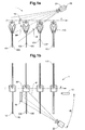
Im Ausführungsbeispiel, wie es in der
Zum Erkennen des Fehlers der Produktgruppe der Klammer K4 genügt es hingegen nicht nur die Vorderseite der Produktgruppe zu betrachten. Es muss zusätzlich auch die Rückseite betrachtet werden um erkennen zu können dass ein drittes überzähliges Produkt 103 in der Klammer K4 gefördert wird.In order to recognize the error of the product group of the bracket K4, however, it is sufficient not only to look at the front of the product group. In addition, the reverse side must also be considered in order to be able to recognize that a
Beim Passieren der Vorrichtung 1 wird das Druckproduktepaar 101, 102 in der Klammer K2 gehalten. Es wird kontrolliert, ob genau zwei Produkte pro Klammer gefördert sind, und ob diese beiden Produkte korrekt in der Klammer positioniert sind. Dazu wird ein oberer Bereich einer Vorderseite 105 der Produktgruppe 101, 102 von einem Strahlprofil P, das mittels Laser 10 erzeugt wird, direkt angestrahlt. Das Strahlprofil P beleuchtet nicht nur den oberen Bereich der Vorderseite 105 direkt, sondern auch einen Spiegel 15 der in Förderrichtung hinter der zu kontrollierenden Produktgruppe der Klammer K2 oberhalb der Produkte 101, 102 angeordnet ist. Mit dem dabei erzeugten Spiegelstrahlprofil SP wird ein oberer Bereich einer Rückseite 106 der Produktgruppe, im vorliegenden Fall des Produkts 101, beaufschlagt. Eine Digitalkamera 20 erfasst ein elektronisches Bild vom direkt beaufschlagten Bereich auf der Vorderseite 105 der Produktgruppe in der Klammer K2 und vom Spiegel 15. Die Kamera ist derart positioniert und ausgerichtet, dass im Spiegelbild der obere Bereich der mit dem Spiegelstrahlprofil SP beaufschlagten Rückseite 106 des zweiten Produkts 101 sichtbar ist. Dank des Spiegels 15 können also Vorder- und Rückseite der Produktgruppe mit einer einzigen Aufnahme zeitgleich optisch erfasst werden. Das elektronische Bild umfasst den zur Produktkontrolle wesentlichen Bereich des auf der Oberfläche der Produkte erzeugten Linienprofils und gleichzeitig den wesentlichen Bereich des im Spiegel 15 gespiegelten Spiegel-Linienprofils als Lichtlinie und als Spiegel-Lichtlinie.When passing the
Da die Produktgruppe in der Klammer K2 korrekt zusammengestellt und korrekt gehalten ist, wird eine erste Messinformation die zum Beispiel basierend auf Kantenpunkten generiert wird zu einem Signal führen, dass die Produktgruppe korrekt zusammengestellt ist und eine zweite Messinformation wird zum Signal führen, dass die Position der Produkte zueinander korrekt ist. Da das elektronische Bild zeitgleich beide Seiten der selben Produktgruppe aufnimmt kann es unmittelbar analysiert und weiterverarbeitet werden und es kann auf eine Zwischenspeicherung verzichtet werden.Since the product group in the bracket K2 is correctly assembled and correctly held, a first measurement information generated, for example, based on edge points will lead to a signal that the product group is correctly assembled and a second measurement information will lead to the signal that the position of the Products to each other is correct. Since the electronic image records both sides of the same product group at the same time, it can be immediately analyzed and further processed and caching can be dispensed with.
In der Kontrollsituation wie sie in der
Dass die Produktgruppe in der Klammer K1 korrekt zusammengestellt und korrekt gehalten ist, kann gemäss der dargestellten Ausführungsform erst zweifelsfrei ermittelt werden, wenn auch der relevante Bereich der Rückseite der Produktgruppe betrachtet wurde. Dies geschieht erst zwei Maschinentakte weiter, wenn sich die Klammer K1 in der Position befindet in sich in zum dargestellten Zeitpunkt der
Gemäss weiterer Ausführungsformen wird das zuerst aufgenommene elektronische Bild, im vorliegenden Fall das Bild der Vorderseite 105 aus Klammer K1, respektive der relevante Bereich mit der Lichtlinie, zusammen mit dem Bildbereich der Rückseite 106' der vorlaufenden Produktgruppe aus Klammer K3 bearbeitet und ausgewertet. Es muss dabei lediglich sichergestellt werden, dass nach der Aufnahme den Bildbereichen, oder den in den weiteren Bildbearbeitungs- und/oder Auswertungsschritten generierten Linien, Messinformationen bis hin zu den Signalen, jeweils die Herkunftsinformation von Produkt oder Produktgruppe eindeutig zugeordnet ist. Ob also ein Ausschnitt des ursprünglich aufgenommenen Bilds, oder der Ausschnitt vom bereits gefilterten oder optimierten Bild, oder eine daraus generierte Linie, daraus generierte Werte oder sogar das Ergebnis der Kontrolle oder ein zugehöriges Teil-Signal zwischengespeichert wird lässt sich auswählen.According to further embodiments, the first recorded electronic image, in the present case the image of the
Entscheidend ist es, dass in allen Fällen das eigentliche Signal, das basierend auf der Messinformation erzeugt wird, auf den elektronischen Bildern der relevanten Bereiche des selben Produkts oder der selben Produktgruppe beruht.It is crucial that in all cases the actual signal, which is generated based on the measurement information, based on the electronic images of the relevant areas of the same product or the same product group.
Mit Hilfe des neuen Verfahrens und der neuen Vorrichtung lässt sich zudem sehr effizient die Lagekontrolle von Produktgruppen, die in einer Klammer gehalten und transportiert werden, auch noch nach dem Beschnitt (zum Beispiel nach einem Dreiseitenbeschnitt) durchführen. Während eine Fehllage eines der beiden Produkte an keiner der beschnittenen Seiten mehr feststellbar ist, lässt sie sich an der vom Greifer gehaltenen Kante mittels des neuen Verfahrens feststellen.With the help of the new method and the new device, it is also possible to very efficiently carry out the position control of product groups which are held and transported in a clamp even after the trimming (for example after a three-side trimming). While a misalignment of one of the two products is no longer detectable on any of the trimmed sides, it can be determined by the new method at the edge held by the gripper.
Für den Fachmann ist es anhand der obigen Ausführungen nachvollziehbar, dass sich je nach Ausrichtung der Projektionsmittel, der Spiegel und der optischen Sensoren nicht nur die geförderten Produkte, sondern auch die bewegten Teile der Fördervorrichtung kontrollieren lassen. In den Ausführungsbeispielen gemäss der Figuren wären dies zum Beispiel die Klammern K1 - K4 die ebenfalls mit Lichtlinie und Spiegel-Lichtlinie beaufschlagt werden könnten und anhand der erfassten elektronischen Bilder von mehr als einer Seite gleichzeitig oder um einen oder mehrere Takte versetzt kontrolliert werden könnten.It is understandable to the person skilled in the art from the above statements that, depending on the orientation of the projection means, the mirror and the optical sensors, not only the conveyed products but also the moving parts of the conveyor device can be checked. In the exemplary embodiments according to the figures, these would be, for example, the brackets K1-K4, which are likewise loaded with a line of light and a mirror line of light could be controlled by the captured electronic images of more than one page simultaneously or offset by one or more bars.
In den dargestellten Ausführungsbeispielen ist aus den
In der
In der Vorrichtung wie sie in der
Eben so ist es aufbauend auf der vorhergehenden technischen Lehre gemäss der Erfindung für den Fachmann offensichtlich, dass das erfindungsgemässe Prinzip zur Kontrolle von mehr als zwei Seiten oder zwei Bereichen von Produkten, Produktgruppen oder Strömen oder von bewegten Anlageteilen verwendet werden kann.It is also evident, based on the preceding technical teaching according to the invention, that the inventive principle can be used to control more than two sides or two regions of products, product groups or streams or of moving plant parts.
- 11
- Kontrollvorrichtungcontrol device
- 1010
- Laserlaser
- 11-1411-14
- Lichtlinienlight lines
- 15, 15'15, 15 '
- Spiegelmirror
- 2020
- Kameracamera
- 101, 101'101, 101 '
- Druckproduktprint product
- 102, 102'102, 102 '
- Druckproduktprint product
- 103103
- Druckproduktprint product
- 105105
- Vorderseitefront
- 106, 106'106, 106 '
- Rückseiteback
- 110110
- obere Kanteupper edge
- FF
- Förderrichtungconveying direction
- KK
- Klammerclip
- PP
- Strahlprofilsbeam profile
- SPSP
- SpiegelstrahlprofilMirror beam profile
Claims (9)
- Optical monitoring method for use in print further processing, comprising:a. guiding a sheet-like printed product (101, 102, 103), a product group or a product stream along a conveying path past at least one optical sensor (20);b. producing at least one beam profile (P);c. deflecting part of a beam profile (P) for producing a mirror beam profile (SP);d. impinging on at least one sheet-like printed product (101, 102, 103), a product group or a product stream, which are guided along a conveying path, with at least one beam profile (P) and at least one mirror beam profile (SP);e. simultaneously producing at least one line profile defined by the beam profile (P) and at least one mirror line profile produced by the mirror beam profile (SP);f. capturing an electronic image using the optical sensor (20), wherein the electronic image comprises at least one region of the line profile and of the mirror line profile, and wherein one of the regions is captured directly and the mirror image of the other region is captured;g. determining from the electronic image at least one product identifier based on the line profile and the mirror line profile;h. generating at least one item of measurement information based on the at least one product identifier; andi. producing at least one signal based on the measurement information, wherein
the line profile and the mirror line profile are directed onto mutually spaced-apart sheet-like printed products or product groups and an electronic image of a line profile is assigned an electronic image of a mirror line profile of the same printed product or the same product group, which mirror line profile has not been recorded at the same time, and at least one product identifier is determined from these two images. - Monitoring method according to Claim 1, characterized in that the mirror light line is produced by reflecting a portion of the at least one beam profile at a first mirror (15, 15').
- Monitoring method according to one of Claims 1 or 2, characterized in that the electronic image comprises the mirror line profile in the first mirror (15, 15').
- Apparatus (1) for carrying out the optical monitoring method according to one of Claims 1 to 3, comprising:a. a projection means (10) for generating at least one beam profile (P) and for directing the at least one beam profile (P) onto a sheet-like printed product (101, 102, 103), a product group or a product stream, which are guided along a conveying path, to produce a line profile defined by a light line;b. at least one first mirror (15, 15') for reflecting at least a section of the beam profile (P);c. at least one optical sensor (20) for capturing an electronic image of the printed product (101, 102, 103), the product group or the product stream, which are guided along the conveying path past the optical sensor (20), wherein the electronic image comprises at least one region of the printed product (101, 102, 103), the product group or the product stream with at least a part of the line profile, which is defined by the light line, and at least one region of the mirror (15, 15') with at least a part of the mirror line profile; andd. an image processing unit, which is configured to ascertain, based on the line profile and the mirror line profile, at least one product identifier from the electronic image, to generate, based on the at least one product identifier, an item of measurement information, and to produce, based on the measurement information, at least one signal, wherein
projection means (10), optical sensor (20) and mirror (15') are arranged such that the beam profile (P) is impinged on a first printed product or a first product group (101, 102) and the mirror beam profile (SP) is impinged on a further printed product (101') or a further product group. - Apparatus according to Claim 4, characterized in that the regions of the sheet-like printed product (101, 102, 103), on which the light line is impinged, are held by the conveying means such that they are arranged approximately plane-parallel with respect to the first mirror (15, 15').
- Apparatus according to Claim 4 or 5, characterized in that the optical sensor (20) is arranged with an optical axis running obliquely with respect to the beam axis of the projection means (10) at an angle α remotely from the products (101, 102, 103) to be monitored.
- Apparatus according to Claim 4 or 5, characterized in that the optical axis of the optical sensor (20) is arranged parallel with respect to the beam axis of the projection means (10).
- Apparatus according to one of Claims 4 to 7, characterized in that the first mirror (15, 15') is positioned such that it reflects the beam profile (P) of the projection means (10) in a region-wise manner.
- Apparatus according to one of Claims 4 to 8, characterized in that at least one first mirror is assigned to the projection means (10) and at least one second mirror is assigned to the optical sensor (20), wherein a mirror beam profile (SP), generated using the first mirror, is directly capturable by the optical sensor (20) and a region in the second mirror, on which the projection means (10) acts directly, is capturable by the optical sensor (20).
Applications Claiming Priority (2)
| Application Number | Priority Date | Filing Date | Title |
|---|---|---|---|
| CH01464/09A CH701910A1 (en) | 2009-09-23 | 2009-09-23 | Optical control procedures for assessing the quality of print finishing. |
| PCT/EP2010/063602 WO2011036086A1 (en) | 2009-09-23 | 2010-09-16 | Optical checking method for evaluating quality in print processing |
Publications (2)
| Publication Number | Publication Date |
|---|---|
| EP2480470A1 EP2480470A1 (en) | 2012-08-01 |
| EP2480470B1 true EP2480470B1 (en) | 2013-08-28 |
Family
ID=41510454
Family Applications (1)
| Application Number | Title | Priority Date | Filing Date |
|---|---|---|---|
| EP10755144.2A Not-in-force EP2480470B1 (en) | 2009-09-23 | 2010-09-16 | Optical checking method for evaluating quality in print processing |
Country Status (4)
| Country | Link |
|---|---|
| EP (1) | EP2480470B1 (en) |
| CH (1) | CH701910A1 (en) |
| DK (1) | DK2480470T3 (en) |
| WO (1) | WO2011036086A1 (en) |
Families Citing this family (1)
| Publication number | Priority date | Publication date | Assignee | Title |
|---|---|---|---|---|
| TWI780451B (en) * | 2020-07-03 | 2022-10-11 | 住華科技股份有限公司 | Automatic pick-and-place apparatus and method of picking and placing optical film |
Family Cites Families (5)
| Publication number | Priority date | Publication date | Assignee | Title |
|---|---|---|---|---|
| GB0418040D0 (en) * | 2004-08-12 | 2004-09-15 | Wessex Technology Opto Electro | Improvements in double feed mail detection |
| US7809158B2 (en) * | 2005-05-02 | 2010-10-05 | Siemens Industry, Inc. | Method and apparatus for detecting doubles in a singulated stream of flat articles |
| EP1910202B1 (en) * | 2005-07-29 | 2013-10-02 | Ferag AG | Method and device for controlling the clamped transportation of flat products |
| EP2256075A3 (en) * | 2007-04-03 | 2010-12-22 | Ferag AG | Method and device for controlling flat products |
| CA2630138C (en) * | 2007-05-16 | 2015-12-01 | Ferag Ag | Method and device for opening printed products |
-
2009
- 2009-09-23 CH CH01464/09A patent/CH701910A1/en not_active Application Discontinuation
-
2010
- 2010-09-16 DK DK10755144.2T patent/DK2480470T3/en active
- 2010-09-16 WO PCT/EP2010/063602 patent/WO2011036086A1/en active Application Filing
- 2010-09-16 EP EP10755144.2A patent/EP2480470B1/en not_active Not-in-force
Also Published As
| Publication number | Publication date |
|---|---|
| WO2011036086A1 (en) | 2011-03-31 |
| CH701910A1 (en) | 2011-03-31 |
| DK2480470T3 (en) | 2013-11-25 |
| EP2480470A1 (en) | 2012-08-01 |
Similar Documents
| Publication | Publication Date | Title |
|---|---|---|
| EP0228500B2 (en) | Method of and device for contactless measurement of the wheel profile of the wheels of railway wheel sets | |
| EP1910202B1 (en) | Method and device for controlling the clamped transportation of flat products | |
| WO2005090950A1 (en) | Method and system for inspecting surfaces | |
| EP2130163B1 (en) | Device and method for counting and detecting flat products | |
| DE102020000581A1 (en) | Device and method for the identification and localization of surface defects | |
| EP2144052A1 (en) | Method and device for detecting and classifying defects | |
| EP2480470B1 (en) | Optical checking method for evaluating quality in print processing | |
| EP2715279A1 (en) | Device and method for measuring the running gear of a motor vehicle | |
| DE102016100437B4 (en) | Device for image control | |
| DE102012005966A1 (en) | Device for generating representation of three dimensional body in form of vehicle, has illumination device for generating light strip, particularly parallel light, where electronic sensor is arranged behind or in front of shadow wall | |
| EP2687837B1 (en) | Method and system for incident light inspection of at least two opposing top panel edges of a moving panel | |
| EP1980516B1 (en) | Method and device for determining the position of webs of material | |
| DE19733297A1 (en) | Contactless optical thickness measuring device | |
| DE102019133695B4 (en) | Laser material processing head, use of a laser material processing head and method for seam tracking in laser material processing | |
| DE102017129737A1 (en) | Apparatus for non-contact, 3D optical detection of an end face of a transversely moving, rod-shaped article of the tobacco processing industry | |
| EP2301877B1 (en) | Optical control method for quality assurance in print finishing | |
| DE202004020330U1 (en) | Inspection device for the edge regions of planar elements, especially glass plates, has a single camera with at least two separate row or matrix imaging areas and a light deflection unit allocated to each row or matrix area | |
| EP1862309B1 (en) | Sensor device | |
| DE102007001989B4 (en) | Arrangement for detecting double prints in mail sorting machines | |
| DE102019102783A1 (en) | Alignment target and method for aligning a camera | |
| DE102019117849B4 (en) | Detection of an object in a surveillance area | |
| DE102007008543A1 (en) | Method and device for determining the state of motion of objects | |
| DE102020114980B4 (en) | DEVICE AND SYSTEM FOR INSPECTING AT LEAST ONE DIFFACTIVE OPTICAL ELEMENT OF A DOCUMENT | |
| DE69733672T2 (en) | METHOD FOR MEASURING THE ORIENTATION OF A SURFACE | |
| DE102015201297B4 (en) | Device and method for determining an alignment between a front marking and a back marking of a document body |
Legal Events
| Date | Code | Title | Description |
|---|---|---|---|
| PUAI | Public reference made under article 153(3) epc to a published international application that has entered the european phase |
Free format text: ORIGINAL CODE: 0009012 |
|
| 17P | Request for examination filed |
Effective date: 20120411 |
|
| AK | Designated contracting states |
Kind code of ref document: A1 Designated state(s): AL AT BE BG CH CY CZ DE DK EE ES FI FR GB GR HR HU IE IS IT LI LT LU LV MC MK MT NL NO PL PT RO SE SI SK SM TR |
|
| DAX | Request for extension of the european patent (deleted) | ||
| GRAP | Despatch of communication of intention to grant a patent |
Free format text: ORIGINAL CODE: EPIDOSNIGR1 |
|
| GRAS | Grant fee paid |
Free format text: ORIGINAL CODE: EPIDOSNIGR3 |
|
| GRAA | (expected) grant |
Free format text: ORIGINAL CODE: 0009210 |
|
| AK | Designated contracting states |
Kind code of ref document: B1 Designated state(s): AL AT BE BG CH CY CZ DE DK EE ES FI FR GB GR HR HU IE IS IT LI LT LU LV MC MK MT NL NO PL PT RO SE SI SK SM TR |
|
| REG | Reference to a national code |
Ref country code: GB Ref legal event code: FG4D Free format text: NOT ENGLISH |
|
| REG | Reference to a national code |
Ref country code: CH Ref legal event code: EP |
|
| REG | Reference to a national code |
Ref country code: AT Ref legal event code: REF Ref document number: 629210 Country of ref document: AT Kind code of ref document: T Effective date: 20130915 |
|
| REG | Reference to a national code |
Ref country code: IE Ref legal event code: FG4D Free format text: LANGUAGE OF EP DOCUMENT: GERMAN |
|
| REG | Reference to a national code |
Ref country code: CH Ref legal event code: NV Representative=s name: RENTSCH PARTNER AG, CH |
|
| REG | Reference to a national code |
Ref country code: DE Ref legal event code: R096 Ref document number: 502010004533 Country of ref document: DE Effective date: 20131024 |
|
| REG | Reference to a national code |
Ref country code: DK Ref legal event code: T3 Effective date: 20131119 |
|
| REG | Reference to a national code |
Ref country code: SE Ref legal event code: TRGR |
|
| REG | Reference to a national code |
Ref country code: LT Ref legal event code: MG4D |
|
| REG | Reference to a national code |
Ref country code: NL Ref legal event code: VDEP Effective date: 20130828 |
|
| PG25 | Lapsed in a contracting state [announced via postgrant information from national office to epo] |
Ref country code: CY Free format text: LAPSE BECAUSE OF FAILURE TO SUBMIT A TRANSLATION OF THE DESCRIPTION OR TO PAY THE FEE WITHIN THE PRESCRIBED TIME-LIMIT Effective date: 20130904 Ref country code: HR Free format text: LAPSE BECAUSE OF FAILURE TO SUBMIT A TRANSLATION OF THE DESCRIPTION OR TO PAY THE FEE WITHIN THE PRESCRIBED TIME-LIMIT Effective date: 20130828 Ref country code: IS Free format text: LAPSE BECAUSE OF FAILURE TO SUBMIT A TRANSLATION OF THE DESCRIPTION OR TO PAY THE FEE WITHIN THE PRESCRIBED TIME-LIMIT Effective date: 20131228 Ref country code: PT Free format text: LAPSE BECAUSE OF FAILURE TO SUBMIT A TRANSLATION OF THE DESCRIPTION OR TO PAY THE FEE WITHIN THE PRESCRIBED TIME-LIMIT Effective date: 20131230 Ref country code: NO Free format text: LAPSE BECAUSE OF FAILURE TO SUBMIT A TRANSLATION OF THE DESCRIPTION OR TO PAY THE FEE WITHIN THE PRESCRIBED TIME-LIMIT Effective date: 20131128 Ref country code: LT Free format text: LAPSE BECAUSE OF FAILURE TO SUBMIT A TRANSLATION OF THE DESCRIPTION OR TO PAY THE FEE WITHIN THE PRESCRIBED TIME-LIMIT Effective date: 20130828 |
|
| REG | Reference to a national code |
Ref country code: NL Ref legal event code: VDEP Effective date: 20130828 |
|
| PG25 | Lapsed in a contracting state [announced via postgrant information from national office to epo] |
Ref country code: LV Free format text: LAPSE BECAUSE OF FAILURE TO SUBMIT A TRANSLATION OF THE DESCRIPTION OR TO PAY THE FEE WITHIN THE PRESCRIBED TIME-LIMIT Effective date: 20130828 Ref country code: FI Free format text: LAPSE BECAUSE OF FAILURE TO SUBMIT A TRANSLATION OF THE DESCRIPTION OR TO PAY THE FEE WITHIN THE PRESCRIBED TIME-LIMIT Effective date: 20130828 Ref country code: PL Free format text: LAPSE BECAUSE OF FAILURE TO SUBMIT A TRANSLATION OF THE DESCRIPTION OR TO PAY THE FEE WITHIN THE PRESCRIBED TIME-LIMIT Effective date: 20130828 Ref country code: GR Free format text: LAPSE BECAUSE OF FAILURE TO SUBMIT A TRANSLATION OF THE DESCRIPTION OR TO PAY THE FEE WITHIN THE PRESCRIBED TIME-LIMIT Effective date: 20131129 Ref country code: SI Free format text: LAPSE BECAUSE OF FAILURE TO SUBMIT A TRANSLATION OF THE DESCRIPTION OR TO PAY THE FEE WITHIN THE PRESCRIBED TIME-LIMIT Effective date: 20130828 |
|
| BERE | Be: lapsed |
Owner name: FERAG AG Effective date: 20130930 |
|
| PG25 | Lapsed in a contracting state [announced via postgrant information from national office to epo] |
Ref country code: CY Free format text: LAPSE BECAUSE OF FAILURE TO SUBMIT A TRANSLATION OF THE DESCRIPTION OR TO PAY THE FEE WITHIN THE PRESCRIBED TIME-LIMIT Effective date: 20130828 |
|
| PG25 | Lapsed in a contracting state [announced via postgrant information from national office to epo] |
Ref country code: RO Free format text: LAPSE BECAUSE OF FAILURE TO SUBMIT A TRANSLATION OF THE DESCRIPTION OR TO PAY THE FEE WITHIN THE PRESCRIBED TIME-LIMIT Effective date: 20130828 Ref country code: NL Free format text: LAPSE BECAUSE OF FAILURE TO SUBMIT A TRANSLATION OF THE DESCRIPTION OR TO PAY THE FEE WITHIN THE PRESCRIBED TIME-LIMIT Effective date: 20130828 Ref country code: EE Free format text: LAPSE BECAUSE OF FAILURE TO SUBMIT A TRANSLATION OF THE DESCRIPTION OR TO PAY THE FEE WITHIN THE PRESCRIBED TIME-LIMIT Effective date: 20130828 Ref country code: SK Free format text: LAPSE BECAUSE OF FAILURE TO SUBMIT A TRANSLATION OF THE DESCRIPTION OR TO PAY THE FEE WITHIN THE PRESCRIBED TIME-LIMIT Effective date: 20130828 Ref country code: CZ Free format text: LAPSE BECAUSE OF FAILURE TO SUBMIT A TRANSLATION OF THE DESCRIPTION OR TO PAY THE FEE WITHIN THE PRESCRIBED TIME-LIMIT Effective date: 20130828 |
|
| PG25 | Lapsed in a contracting state [announced via postgrant information from national office to epo] |
Ref country code: MC Free format text: LAPSE BECAUSE OF FAILURE TO SUBMIT A TRANSLATION OF THE DESCRIPTION OR TO PAY THE FEE WITHIN THE PRESCRIBED TIME-LIMIT Effective date: 20130828 Ref country code: ES Free format text: LAPSE BECAUSE OF FAILURE TO SUBMIT A TRANSLATION OF THE DESCRIPTION OR TO PAY THE FEE WITHIN THE PRESCRIBED TIME-LIMIT Effective date: 20130828 Ref country code: IT Free format text: LAPSE BECAUSE OF FAILURE TO SUBMIT A TRANSLATION OF THE DESCRIPTION OR TO PAY THE FEE WITHIN THE PRESCRIBED TIME-LIMIT Effective date: 20130828 |
|
| REG | Reference to a national code |
Ref country code: DE Ref legal event code: R097 Ref document number: 502010004533 Country of ref document: DE |
|
| REG | Reference to a national code |
Ref country code: IE Ref legal event code: MM4A |
|
| PLBE | No opposition filed within time limit |
Free format text: ORIGINAL CODE: 0009261 |
|
| STAA | Information on the status of an ep patent application or granted ep patent |
Free format text: STATUS: NO OPPOSITION FILED WITHIN TIME LIMIT |
|
| PG25 | Lapsed in a contracting state [announced via postgrant information from national office to epo] |
Ref country code: BE Free format text: LAPSE BECAUSE OF NON-PAYMENT OF DUE FEES Effective date: 20130930 Ref country code: IE Free format text: LAPSE BECAUSE OF NON-PAYMENT OF DUE FEES Effective date: 20130916 |
|
| 26N | No opposition filed |
Effective date: 20140530 |
|
| REG | Reference to a national code |
Ref country code: FR Ref legal event code: ST Effective date: 20140709 |
|
| REG | Reference to a national code |
Ref country code: DE Ref legal event code: R097 Ref document number: 502010004533 Country of ref document: DE Effective date: 20140530 |
|
| PGFP | Annual fee paid to national office [announced via postgrant information from national office to epo] |
Ref country code: DK Payment date: 20140919 Year of fee payment: 5 |
|
| PG25 | Lapsed in a contracting state [announced via postgrant information from national office to epo] |
Ref country code: FR Free format text: LAPSE BECAUSE OF NON-PAYMENT OF DUE FEES Effective date: 20131028 |
|
| GBPC | Gb: european patent ceased through non-payment of renewal fee |
Effective date: 20140916 |
|
| PG25 | Lapsed in a contracting state [announced via postgrant information from national office to epo] |
Ref country code: SM Free format text: LAPSE BECAUSE OF FAILURE TO SUBMIT A TRANSLATION OF THE DESCRIPTION OR TO PAY THE FEE WITHIN THE PRESCRIBED TIME-LIMIT Effective date: 20130828 |
|
| PG25 | Lapsed in a contracting state [announced via postgrant information from national office to epo] |
Ref country code: TR Free format text: LAPSE BECAUSE OF FAILURE TO SUBMIT A TRANSLATION OF THE DESCRIPTION OR TO PAY THE FEE WITHIN THE PRESCRIBED TIME-LIMIT Effective date: 20130828 Ref country code: MT Free format text: LAPSE BECAUSE OF FAILURE TO SUBMIT A TRANSLATION OF THE DESCRIPTION OR TO PAY THE FEE WITHIN THE PRESCRIBED TIME-LIMIT Effective date: 20130828 |
|
| PG25 | Lapsed in a contracting state [announced via postgrant information from national office to epo] |
Ref country code: HU Free format text: LAPSE BECAUSE OF FAILURE TO SUBMIT A TRANSLATION OF THE DESCRIPTION OR TO PAY THE FEE WITHIN THE PRESCRIBED TIME-LIMIT; INVALID AB INITIO Effective date: 20100916 Ref country code: GB Free format text: LAPSE BECAUSE OF NON-PAYMENT OF DUE FEES Effective date: 20140916 Ref country code: BG Free format text: LAPSE BECAUSE OF FAILURE TO SUBMIT A TRANSLATION OF THE DESCRIPTION OR TO PAY THE FEE WITHIN THE PRESCRIBED TIME-LIMIT Effective date: 20130828 Ref country code: LU Free format text: LAPSE BECAUSE OF NON-PAYMENT OF DUE FEES Effective date: 20130916 Ref country code: MK Free format text: LAPSE BECAUSE OF FAILURE TO SUBMIT A TRANSLATION OF THE DESCRIPTION OR TO PAY THE FEE WITHIN THE PRESCRIBED TIME-LIMIT Effective date: 20130828 |
|
| PGFP | Annual fee paid to national office [announced via postgrant information from national office to epo] |
Ref country code: SE Payment date: 20150923 Year of fee payment: 6 |
|
| REG | Reference to a national code |
Ref country code: DK Ref legal event code: EBP Effective date: 20150930 |
|
| PG25 | Lapsed in a contracting state [announced via postgrant information from national office to epo] |
Ref country code: DK Free format text: LAPSE BECAUSE OF NON-PAYMENT OF DUE FEES Effective date: 20150930 |
|
| PGFP | Annual fee paid to national office [announced via postgrant information from national office to epo] |
Ref country code: DE Payment date: 20160921 Year of fee payment: 7 |
|
| REG | Reference to a national code |
Ref country code: AT Ref legal event code: MM01 Ref document number: 629210 Country of ref document: AT Kind code of ref document: T Effective date: 20150916 |
|
| PG25 | Lapsed in a contracting state [announced via postgrant information from national office to epo] |
Ref country code: AT Free format text: LAPSE BECAUSE OF NON-PAYMENT OF DUE FEES Effective date: 20150916 |
|
| PG25 | Lapsed in a contracting state [announced via postgrant information from national office to epo] |
Ref country code: SE Free format text: LAPSE BECAUSE OF NON-PAYMENT OF DUE FEES Effective date: 20160917 |
|
| REG | Reference to a national code |
Ref country code: SE Ref legal event code: EUG |
|
| REG | Reference to a national code |
Ref country code: DE Ref legal event code: R119 Ref document number: 502010004533 Country of ref document: DE |
|
| PG25 | Lapsed in a contracting state [announced via postgrant information from national office to epo] |
Ref country code: DE Free format text: LAPSE BECAUSE OF NON-PAYMENT OF DUE FEES Effective date: 20180404 |
|
| PG25 | Lapsed in a contracting state [announced via postgrant information from national office to epo] |
Ref country code: AL Free format text: LAPSE BECAUSE OF FAILURE TO SUBMIT A TRANSLATION OF THE DESCRIPTION OR TO PAY THE FEE WITHIN THE PRESCRIBED TIME-LIMIT Effective date: 20130828 |
|
| PGFP | Annual fee paid to national office [announced via postgrant information from national office to epo] |
Ref country code: CH Payment date: 20181128 Year of fee payment: 9 |
|
| REG | Reference to a national code |
Ref country code: CH Ref legal event code: PL |
|
| PG25 | Lapsed in a contracting state [announced via postgrant information from national office to epo] |
Ref country code: LI Free format text: LAPSE BECAUSE OF NON-PAYMENT OF DUE FEES Effective date: 20190930 Ref country code: CH Free format text: LAPSE BECAUSE OF NON-PAYMENT OF DUE FEES Effective date: 20190930 |
|
| P01 | Opt-out of the competence of the unified patent court (upc) registered |
Effective date: 20230507 |