EP2480439B1 - Procede d'apprentisage du point de lechage d'un embrayage par la courbe caracteristique de l'embrayage pour un vehicule hybride - Google Patents
Procede d'apprentisage du point de lechage d'un embrayage par la courbe caracteristique de l'embrayage pour un vehicule hybride Download PDFInfo
- Publication number
- EP2480439B1 EP2480439B1 EP10770851.3A EP10770851A EP2480439B1 EP 2480439 B1 EP2480439 B1 EP 2480439B1 EP 10770851 A EP10770851 A EP 10770851A EP 2480439 B1 EP2480439 B1 EP 2480439B1
- Authority
- EP
- European Patent Office
- Prior art keywords
- clutch
- electric machine
- torque
- heat engine
- point
- Prior art date
- Legal status (The legal status is an assumption and is not a legal conclusion. Google has not performed a legal analysis and makes no representation as to the accuracy of the status listed.)
- Not-in-force
Links
Images

Classifications
-
- B—PERFORMING OPERATIONS; TRANSPORTING
- B60—VEHICLES IN GENERAL
- B60W—CONJOINT CONTROL OF VEHICLE SUB-UNITS OF DIFFERENT TYPE OR DIFFERENT FUNCTION; CONTROL SYSTEMS SPECIALLY ADAPTED FOR HYBRID VEHICLES; ROAD VEHICLE DRIVE CONTROL SYSTEMS FOR PURPOSES NOT RELATED TO THE CONTROL OF A PARTICULAR SUB-UNIT
- B60W10/00—Conjoint control of vehicle sub-units of different type or different function
- B60W10/02—Conjoint control of vehicle sub-units of different type or different function including control of driveline clutches
-
- B—PERFORMING OPERATIONS; TRANSPORTING
- B60—VEHICLES IN GENERAL
- B60K—ARRANGEMENT OR MOUNTING OF PROPULSION UNITS OR OF TRANSMISSIONS IN VEHICLES; ARRANGEMENT OR MOUNTING OF PLURAL DIVERSE PRIME-MOVERS IN VEHICLES; AUXILIARY DRIVES FOR VEHICLES; INSTRUMENTATION OR DASHBOARDS FOR VEHICLES; ARRANGEMENTS IN CONNECTION WITH COOLING, AIR INTAKE, GAS EXHAUST OR FUEL SUPPLY OF PROPULSION UNITS IN VEHICLES
- B60K6/00—Arrangement or mounting of plural diverse prime-movers for mutual or common propulsion, e.g. hybrid propulsion systems comprising electric motors and internal combustion engines
- B60K6/20—Arrangement or mounting of plural diverse prime-movers for mutual or common propulsion, e.g. hybrid propulsion systems comprising electric motors and internal combustion engines the prime-movers consisting of electric motors and internal combustion engines, e.g. HEVs
- B60K6/22—Arrangement or mounting of plural diverse prime-movers for mutual or common propulsion, e.g. hybrid propulsion systems comprising electric motors and internal combustion engines the prime-movers consisting of electric motors and internal combustion engines, e.g. HEVs characterised by apparatus, components or means specially adapted for HEVs
- B60K6/38—Arrangement or mounting of plural diverse prime-movers for mutual or common propulsion, e.g. hybrid propulsion systems comprising electric motors and internal combustion engines the prime-movers consisting of electric motors and internal combustion engines, e.g. HEVs characterised by apparatus, components or means specially adapted for HEVs characterised by the driveline clutches
-
- B—PERFORMING OPERATIONS; TRANSPORTING
- B60—VEHICLES IN GENERAL
- B60K—ARRANGEMENT OR MOUNTING OF PROPULSION UNITS OR OF TRANSMISSIONS IN VEHICLES; ARRANGEMENT OR MOUNTING OF PLURAL DIVERSE PRIME-MOVERS IN VEHICLES; AUXILIARY DRIVES FOR VEHICLES; INSTRUMENTATION OR DASHBOARDS FOR VEHICLES; ARRANGEMENTS IN CONNECTION WITH COOLING, AIR INTAKE, GAS EXHAUST OR FUEL SUPPLY OF PROPULSION UNITS IN VEHICLES
- B60K6/00—Arrangement or mounting of plural diverse prime-movers for mutual or common propulsion, e.g. hybrid propulsion systems comprising electric motors and internal combustion engines
- B60K6/20—Arrangement or mounting of plural diverse prime-movers for mutual or common propulsion, e.g. hybrid propulsion systems comprising electric motors and internal combustion engines the prime-movers consisting of electric motors and internal combustion engines, e.g. HEVs
- B60K6/42—Arrangement or mounting of plural diverse prime-movers for mutual or common propulsion, e.g. hybrid propulsion systems comprising electric motors and internal combustion engines the prime-movers consisting of electric motors and internal combustion engines, e.g. HEVs characterised by the architecture of the hybrid electric vehicle
- B60K6/48—Parallel type
-
- B—PERFORMING OPERATIONS; TRANSPORTING
- B60—VEHICLES IN GENERAL
- B60W—CONJOINT CONTROL OF VEHICLE SUB-UNITS OF DIFFERENT TYPE OR DIFFERENT FUNCTION; CONTROL SYSTEMS SPECIALLY ADAPTED FOR HYBRID VEHICLES; ROAD VEHICLE DRIVE CONTROL SYSTEMS FOR PURPOSES NOT RELATED TO THE CONTROL OF A PARTICULAR SUB-UNIT
- B60W10/00—Conjoint control of vehicle sub-units of different type or different function
- B60W10/04—Conjoint control of vehicle sub-units of different type or different function including control of propulsion units
- B60W10/06—Conjoint control of vehicle sub-units of different type or different function including control of propulsion units including control of combustion engines
-
- B—PERFORMING OPERATIONS; TRANSPORTING
- B60—VEHICLES IN GENERAL
- B60W—CONJOINT CONTROL OF VEHICLE SUB-UNITS OF DIFFERENT TYPE OR DIFFERENT FUNCTION; CONTROL SYSTEMS SPECIALLY ADAPTED FOR HYBRID VEHICLES; ROAD VEHICLE DRIVE CONTROL SYSTEMS FOR PURPOSES NOT RELATED TO THE CONTROL OF A PARTICULAR SUB-UNIT
- B60W10/00—Conjoint control of vehicle sub-units of different type or different function
- B60W10/04—Conjoint control of vehicle sub-units of different type or different function including control of propulsion units
- B60W10/08—Conjoint control of vehicle sub-units of different type or different function including control of propulsion units including control of electric propulsion units, e.g. motors or generators
-
- B—PERFORMING OPERATIONS; TRANSPORTING
- B60—VEHICLES IN GENERAL
- B60W—CONJOINT CONTROL OF VEHICLE SUB-UNITS OF DIFFERENT TYPE OR DIFFERENT FUNCTION; CONTROL SYSTEMS SPECIALLY ADAPTED FOR HYBRID VEHICLES; ROAD VEHICLE DRIVE CONTROL SYSTEMS FOR PURPOSES NOT RELATED TO THE CONTROL OF A PARTICULAR SUB-UNIT
- B60W20/00—Control systems specially adapted for hybrid vehicles
-
- F—MECHANICAL ENGINEERING; LIGHTING; HEATING; WEAPONS; BLASTING
- F16—ENGINEERING ELEMENTS AND UNITS; GENERAL MEASURES FOR PRODUCING AND MAINTAINING EFFECTIVE FUNCTIONING OF MACHINES OR INSTALLATIONS; THERMAL INSULATION IN GENERAL
- F16D—COUPLINGS FOR TRANSMITTING ROTATION; CLUTCHES; BRAKES
- F16D48/00—External control of clutches
- F16D48/06—Control by electric or electronic means, e.g. of fluid pressure
-
- B—PERFORMING OPERATIONS; TRANSPORTING
- B60—VEHICLES IN GENERAL
- B60W—CONJOINT CONTROL OF VEHICLE SUB-UNITS OF DIFFERENT TYPE OR DIFFERENT FUNCTION; CONTROL SYSTEMS SPECIALLY ADAPTED FOR HYBRID VEHICLES; ROAD VEHICLE DRIVE CONTROL SYSTEMS FOR PURPOSES NOT RELATED TO THE CONTROL OF A PARTICULAR SUB-UNIT
- B60W50/00—Details of control systems for road vehicle drive control not related to the control of a particular sub-unit, e.g. process diagnostic or vehicle driver interfaces
- B60W2050/0001—Details of the control system
- B60W2050/0019—Control system elements or transfer functions
- B60W2050/0028—Mathematical models, e.g. for simulation
- B60W2050/0031—Mathematical model of the vehicle
-
- B—PERFORMING OPERATIONS; TRANSPORTING
- B60—VEHICLES IN GENERAL
- B60W—CONJOINT CONTROL OF VEHICLE SUB-UNITS OF DIFFERENT TYPE OR DIFFERENT FUNCTION; CONTROL SYSTEMS SPECIALLY ADAPTED FOR HYBRID VEHICLES; ROAD VEHICLE DRIVE CONTROL SYSTEMS FOR PURPOSES NOT RELATED TO THE CONTROL OF A PARTICULAR SUB-UNIT
- B60W2510/00—Input parameters relating to a particular sub-units
- B60W2510/02—Clutches
- B60W2510/0208—Clutch engagement state, e.g. engaged or disengaged
-
- B—PERFORMING OPERATIONS; TRANSPORTING
- B60—VEHICLES IN GENERAL
- B60W—CONJOINT CONTROL OF VEHICLE SUB-UNITS OF DIFFERENT TYPE OR DIFFERENT FUNCTION; CONTROL SYSTEMS SPECIALLY ADAPTED FOR HYBRID VEHICLES; ROAD VEHICLE DRIVE CONTROL SYSTEMS FOR PURPOSES NOT RELATED TO THE CONTROL OF A PARTICULAR SUB-UNIT
- B60W2510/00—Input parameters relating to a particular sub-units
- B60W2510/02—Clutches
- B60W2510/0208—Clutch engagement state, e.g. engaged or disengaged
- B60W2510/0225—Clutch actuator position
-
- F—MECHANICAL ENGINEERING; LIGHTING; HEATING; WEAPONS; BLASTING
- F16—ENGINEERING ELEMENTS AND UNITS; GENERAL MEASURES FOR PRODUCING AND MAINTAINING EFFECTIVE FUNCTIONING OF MACHINES OR INSTALLATIONS; THERMAL INSULATION IN GENERAL
- F16D—COUPLINGS FOR TRANSMITTING ROTATION; CLUTCHES; BRAKES
- F16D2500/00—External control of clutches by electric or electronic means
- F16D2500/10—System to be controlled
- F16D2500/106—Engine
- F16D2500/1066—Hybrid
-
- F—MECHANICAL ENGINEERING; LIGHTING; HEATING; WEAPONS; BLASTING
- F16—ENGINEERING ELEMENTS AND UNITS; GENERAL MEASURES FOR PRODUCING AND MAINTAINING EFFECTIVE FUNCTIONING OF MACHINES OR INSTALLATIONS; THERMAL INSULATION IN GENERAL
- F16D—COUPLINGS FOR TRANSMITTING ROTATION; CLUTCHES; BRAKES
- F16D2500/00—External control of clutches by electric or electronic means
- F16D2500/50—Problem to be solved by the control system
- F16D2500/502—Relating the clutch
- F16D2500/50236—Adaptations of the clutch characteristics, e.g. curve clutch capacity torque - clutch actuator displacement
-
- F—MECHANICAL ENGINEERING; LIGHTING; HEATING; WEAPONS; BLASTING
- F16—ENGINEERING ELEMENTS AND UNITS; GENERAL MEASURES FOR PRODUCING AND MAINTAINING EFFECTIVE FUNCTIONING OF MACHINES OR INSTALLATIONS; THERMAL INSULATION IN GENERAL
- F16D—COUPLINGS FOR TRANSMITTING ROTATION; CLUTCHES; BRAKES
- F16D2500/00—External control of clutches by electric or electronic means
- F16D2500/50—Problem to be solved by the control system
- F16D2500/502—Relating the clutch
- F16D2500/50245—Calibration or recalibration of the clutch touch-point
- F16D2500/50266—Way of detection
- F16D2500/50275—Estimation of the displacement of the clutch touch-point due to the modification of relevant parameters, e.g. temperature, wear
-
- F—MECHANICAL ENGINEERING; LIGHTING; HEATING; WEAPONS; BLASTING
- F16—ENGINEERING ELEMENTS AND UNITS; GENERAL MEASURES FOR PRODUCING AND MAINTAINING EFFECTIVE FUNCTIONING OF MACHINES OR INSTALLATIONS; THERMAL INSULATION IN GENERAL
- F16D—COUPLINGS FOR TRANSMITTING ROTATION; CLUTCHES; BRAKES
- F16D2500/00—External control of clutches by electric or electronic means
- F16D2500/50—Problem to be solved by the control system
- F16D2500/502—Relating the clutch
- F16D2500/50245—Calibration or recalibration of the clutch touch-point
- F16D2500/50266—Way of detection
- F16D2500/50281—Transmitted torque
-
- F—MECHANICAL ENGINEERING; LIGHTING; HEATING; WEAPONS; BLASTING
- F16—ENGINEERING ELEMENTS AND UNITS; GENERAL MEASURES FOR PRODUCING AND MAINTAINING EFFECTIVE FUNCTIONING OF MACHINES OR INSTALLATIONS; THERMAL INSULATION IN GENERAL
- F16D—COUPLINGS FOR TRANSMITTING ROTATION; CLUTCHES; BRAKES
- F16D2500/00—External control of clutches by electric or electronic means
- F16D2500/70—Details about the implementation of the control system
- F16D2500/702—Look-up tables
- F16D2500/70252—Clutch torque
- F16D2500/70264—Stroke
-
- F—MECHANICAL ENGINEERING; LIGHTING; HEATING; WEAPONS; BLASTING
- F16—ENGINEERING ELEMENTS AND UNITS; GENERAL MEASURES FOR PRODUCING AND MAINTAINING EFFECTIVE FUNCTIONING OF MACHINES OR INSTALLATIONS; THERMAL INSULATION IN GENERAL
- F16D—COUPLINGS FOR TRANSMITTING ROTATION; CLUTCHES; BRAKES
- F16D2500/00—External control of clutches by electric or electronic means
- F16D2500/70—Details about the implementation of the control system
- F16D2500/706—Strategy of control
- F16D2500/70673—Statistical calculations
- F16D2500/70684—Statistical calculations using regressions
-
- Y—GENERAL TAGGING OF NEW TECHNOLOGICAL DEVELOPMENTS; GENERAL TAGGING OF CROSS-SECTIONAL TECHNOLOGIES SPANNING OVER SEVERAL SECTIONS OF THE IPC; TECHNICAL SUBJECTS COVERED BY FORMER USPC CROSS-REFERENCE ART COLLECTIONS [XRACs] AND DIGESTS
- Y02—TECHNOLOGIES OR APPLICATIONS FOR MITIGATION OR ADAPTATION AGAINST CLIMATE CHANGE
- Y02T—CLIMATE CHANGE MITIGATION TECHNOLOGIES RELATED TO TRANSPORTATION
- Y02T10/00—Road transport of goods or passengers
- Y02T10/60—Other road transportation technologies with climate change mitigation effect
- Y02T10/62—Hybrid vehicles
Definitions
- the invention relates to a method of learning the point of licking of a clutch by the characteristic curve of the clutch for a hybrid vehicle.
- the object of the invention is in particular to allow precise determination of this licking point.
- the invention finds a particularly advantageous application in the field of hybrid vehicles of the parallel type.
- These parallel hybrid vehicles are equipped with two types of energy, thermal and electrical, the combination of which ensures their traction while optimizing energy efficiency and thus reducing consumption and pollution.
- These parallel hybrid vehicles are capable of driving independently thanks to the thermal energy of the internal combustion engine or the electrical energy of an electric machine.
- the power train of such a vehicle comprises a clutch installed between the heat engine and the electric machine, this electric machine being connected to the wheels via a gearbox.
- the machine is connected to a battery from which it takes energy when the machine is operating in motor mode (especially when driving in the city) and to which it supplies energy when it is operating in generator mode (during especially braking and driving on the motorway).
- the licking point of the clutch corresponds to the position of the clutch where the discs begin to come into friction with each other, so that torque begins to be transmitted by the clutch.
- the licking point makes it possible to reset the position / torque transfer function and thus to control the torque transmitted by the clutch.
- the purpose of the function of determining the licking point is to gain reliability and consistency on the torque transmission services by the clutch (start and change ratio).
- the Figure 1 shows the shape of the curve a of the engine speed, the curve b of the speed of the electric machine as well as the curve c of the position of the clutch as a function of time during the implementation of this process of the state of the art.
- the position PO corresponds to an open position of the clutch; while the position PF corresponds to a closed position of the clutch.
- the thermal engine being started and the clutch being open to the maximum it is realized over the period TA between times t0 and t1 a speed control of the engine to a given target.
- the engine speed stabilized at time t1 it is realized over the period TB between times t1 and t2 a slow closing of the clutch in order to transmit a low torque to the electric machine and thus allow its revving .
- a delta speed of the electric machine greater than a calibrated threshold
- we memorize the position of the clutch actuator for example at the concentric stop to deduce the Licking point PL of the clutch in the conditions of wear and temperature of use of the vehicle.
- This technique has the advantage of being simple but poses a problem of learning accuracy in the case of hybrid vehicles. Indeed, on the intended hybrid architecture, the electrical machine being mechanically linked to the primary shaft, it provides significant inertia and non-linear friction. Therefore, it is very difficult to rotate the primary shaft and thus to detect a low torque transmitted by the clutch. In addition, the non-linearity of the friction of the electric machine at low speed causes dispersion on the measurement of the point of licking.
- the document is also known FR-2823545 which teaches a learning process from the licking point of a stationary vehicle, with the engine running, gradually closing the clutch until it detects a reaction point of the engine or transmission.
- the position of the clutch stop corresponding to this point is stored in memory as a new clutch management reference.
- the purpose of this method is to perform learning of the licking point by observing in real time (continuously) the evolution of a reaction signal and the comparison with a detection threshold.
- several measuring points are determined at different points of the characteristic of the torque transmissible by the clutch in order to determine by extrapolation and therefore with greater precision the position of the licking point.
- the document EP-0883509 describes learning of the licking point by continuously observing the evolution of the engine speed during a progressive clutch closure. Once a criterion of evolution of the engine speed has been detected, a single known characteristic of the torque transmissible by the clutch is used to determine the point of licking. Contrary to the invention, this method is applied only during a change of downward ratio when the new gear is engaged and the clutch closes gradually. In contrast to the invention, this method does not allow each new training the reconstitution of a characteristic curve of the clutch updated from several measurement points.
- the document FR-2887606 presents a method of adapting the laws of behavior of the clutch of a hybrid vehicle according to the use of the clutch.
- the method performs a self-adaptation from interpolation of the laws of behavior.
- this method is not intended to achieve learning of the licking point but to provide a real-time update of the torque characteristic of the clutch by interpolation between two different laws of behavior and by self-adaptation . In no case, it is a question of learning the position of the point of licking as is the case in the invention.
- the document FR-2859258 discloses a method for selecting a clutch actuator behavior curve from those previously stored as a clutch closure / opening control law. The selection is based on physical measurements that determine the actual licking point and the actuator position under certain conditions. However, the problem of this method is completely different from that of the invention. Indeed, in the document FR-2859258 , the goal is to accurately determine the torque characteristic of the clutch as realistic as possible at a given time. For this purpose, the licking point as well as other torque measurement points transmittable by the clutch are used as incoming data to determine the correct law (clutch / torque position) to be used. On the other hand, in the invention the opposite is done, that is to say that a clutch / clutch torque characteristic is measured in order to determine by extrapolation the licking point to be taken. into account.
- the document DE-A-10 2007 050987 describes a method for determining a licking point of a clutch connected on the one hand to a heat engine and on the other hand to an electric machine, this electric machine being connected to the wheels of the vehicle.
- the invention solves the disadvantages of existing methods.
- the licking point is determined by calculating and storing the torque transmitted between the heat engine and the electric machine for different positions of the clutch. From these stored couples (torque transmitted by the clutch, position of the clutch), a clutch position value corresponding to the licking point is determined, preferably in real time, by extrapolation.
- the invention makes it possible to learn the point of licking more precisely than the known techniques by using the electric machine in a zone of linear behavior where the losses of the electric machine and the gearbox are linear.
- the invention also makes it possible to reduce the slip time of the clutch and thus to reduce the temperature rises which could artificially shift the characteristic of the clutch.
- the clutch position is measured at the concentric abutment of the clutch.
- the calibrated threshold is of the order of 50trs / min.
- a quadratic regression is performed using the least squares method on the points obtained experimentally.
- the regression curve is obtained using a characteristic curve beam of the reference clutch.
- the characteristic curves of the reference clutch have a fixed reference point when the clutch is completely closed.
- the Figure 2 shows a schematic representation of a traction chain 1 of a hybrid vehicle of the parallel type implementing the method according to the invention.
- This traction chain 1 comprises a coupling / decoupling system 2 formed by a dry clutch, wet or otherwise connected on the one hand to an internal combustion engine 3, gasoline, diesel or other equipped with its flywheel 4 and on the other hand to an electric machine.
- This machine 7 is located on the input shaft of a system 9 of reduction ratio N discrete reports formed by a manual gearbox, automatic, DCT, or other, this system 9 of gearing having its output shaft connected to the wheels 8 of the vehicle.
- a power battery 10 is connected to the electric machine 7.
- the machine 7 When the speed of the vehicle is below a threshold speed (of the order of 50km) during urban driving in particular, the machine 7 operates in motor mode and draws energy from the battery 10; while when the speed of the vehicle is greater than the threshold speed for driving on the motorway, or during energy recovery phases during braking in particular, the machine 7 operates in generator mode and provides power to the battery 10 .
- a system 12 for independent starting of the thermal motor 3 formed by a controlled starter, a "Stop & Start” system or any other type of adapted system is related to the thermal engine 3 to facilitate its start.
- Each member 2, 3, 7, 9, 10, 12 is controlled by a close control computer 2.1, 3.1, 7.1, 9.1, 10.1, 12.1 which is itself controlled by a single supervision computer 15 which makes the decisions and synchronizes actions to respond to the driver's wishes.
- This supervisor 15 depending on the life situations and the state of the vehicle, controls the traction chain 1, decides on the driving mode, coordinates all the transient phases and chooses the operating points in order to optimize the fuel consumption and depollution.
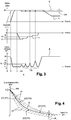
- the Figure 3 shows the shape of the speed curve d of the thermal motor 3 (in phantom), the e speed curve of the electric machine 7 (solid line), the f-curve of the electric machine 7 as well as of the curve g of the position of the clutch 2 as a function of time during the implementation of this method. It is noted that the position PO corresponds to an open position of the clutch 2; while the position PF corresponds to a closed position of the clutch 2.
- the thermal motor 3 is started and driven in regime.
- the clutch 2 is preferably open at most (PO position), the computer 15 controls a torque control of the electric machine 7 to zero torque.
- the computer 15 controls the progressive closing of the clutch 2 to the maximum position PF and pilot mode thermal motor 3 and the machine 7 electric to the same setpoint value Wc.
- the computer 15 controls the electric machine 7 with a reference C1 of negative torque.
- the supervisor 15 controls a slow opening of the clutch 2 until reaching the slip.
- the position P1 of the clutch actuator 2 is stored, for example at the level of the concentric abutment, for this setpoint torque C1 corresponding to the torque transmissible by the clutch 2.
- the computer 15 immediately commands, just after t4, the closing of the clutch 2, this closure being entirely realized at time t5.
- the calibratable threshold DR is of the order of 50 rpm.
- the regression is obtained by means of a characteristic curve beam 17 of the reference clutch preferably all having a fixed reference point PR when the clutch 2 is completely closed.
- This quadratic regression is preferably performed using the least squares method on the points (Ci, Pi) obtained experimentally.
Landscapes
- Engineering & Computer Science (AREA)
- Chemical & Material Sciences (AREA)
- Combustion & Propulsion (AREA)
- Mechanical Engineering (AREA)
- Transportation (AREA)
- General Engineering & Computer Science (AREA)
- Automation & Control Theory (AREA)
- Physics & Mathematics (AREA)
- Fluid Mechanics (AREA)
- Hydraulic Clutches, Magnetic Clutches, Fluid Clutches, And Fluid Joints (AREA)
Description
- L'invention concerne un procédé d'apprentissage du point de léchage d'un embrayage par la courbe caractéristique de l'embrayage pour un véhicule hybride. L'invention a notamment pour but de permettre la détermination précise de ce point de léchage. L'invention trouve une application particulièrement avantageuse dans le domaine des véhicules hybrides de type parallèle.
- Ces véhicules hybrides parallèles sont dotés de deux types d'énergie, thermique et électrique, dont la combinaison permet de garantir leur traction tout en optimisant le rendement énergétique et donc de diminuer la consommation et la pollution. Ces véhicules hybrides parallèles sont capables de rouler indépendamment grâce à l'énergie thermique du moteur à combustion interne ou l'énergie électrique d'une machine électrique.
- A cet effet, la chaîne de traction d'un tel véhicule comporte un embrayage installé entre le moteur thermique et la machine électrique, cette machine électrique étant reliée aux roues par l'intermédiaire d'une boîte de vitesses. La machine est en relation avec une batterie à laquelle elle prélève de l'énergie lorsque la machine fonctionne en mode moteur (lors du roulage en ville notamment) et à laquelle elle fournit de l'énergie lorsqu'elle fonctionne en mode générateur (lors des freinages notamment et des roulages sur autoroute).
- Le point de léchage de l'embrayage correspond à la position de l'embrayage où les disques commencent à entrer en frottement l'un avec l'autre, de sorte que du couple commence à être transmis par l'embrayage. Le point de léchage permet de recaler la fonction de transfert position/couple et ainsi maîtriser le couple transmis par l'embrayage. L'objectif de la fonction de détermination du point de léchage est donc de gagner en fiabilité et en constance sur les prestations de transmission de couple par l'embrayage (démarrage et changement de rapport).
- On connaît des boîtes de vitesses manuelles pilotées ou hybrides pour lesquelles l'apprentissage du point de léchage est réalisé moteur thermique tournant, boîte de vitesses au neutre et par détection de la mise en rotation de l'arbre primaire. La
Figure 1 montre l'allure de la courbe a de régime du moteur thermique, de la courbe b de régime de la machine électrique ainsi que de la courbe c de la position de l'embrayage en fonction du temps lors de la mise en oeuvre de ce procédé de l'état de la technique. La position PO correspond à une position ouverte de l'embrayage ; tandis que la position PF correspond à une position fermée de l'embrayage. - Ainsi le moteur thermique étant démarré et l'embrayage étant ouvert au maximum, on réalise sur la période TA entre les instants t0 et t1 une régulation de régime du moteur thermique vers une consigne donnée. Une fois le régime du moteur thermique stabilisé à l'instant t1, on réalise sur la période TB entre les instants t1 et t2 une fermeture lente de l'embrayage afin de transmettre un couple faible à la machine électrique et permettre ainsi sa montée en régime. Dès que l'on détecte à l'instant t2 un delta de régime de la machine électrique supérieur à un seuil calibrable, on mémorise la position de l'actionneur d'embrayage (par exemple au niveau de la butée concentrique) pour en déduire le point de léchage PL de l'embrayage dans les conditions d'usure et de température d'utilisation du véhicule.
- Cette technique présente l'avantage d'être simple mais pose un problème de précision de l'apprentissage dans le cas des véhicules hybrides. En effet, sur l'architecture hybride visée, la machine électrique étant mécaniquement liée à l'arbre primaire, elle apporte une inertie importante ainsi que des frottements non linéaires. Dès lors, il est très difficile de mettre en rotation l'arbre primaire et donc de détecter un couple faible transmis par l'embrayage. De plus, la non linéarité des frottements de la machine électrique à régime faible entraîne de la dispersion sur la mesure du point de léchage.
- On connaît également le document
FR-2823545 - Le document
EP-0883509 décrit un apprentissage du point de léchage par observation en continu de l'évolution du régime moteur lors d'une fermeture embrayage progressive. Une fois un critère d'évolution de régime moteur détecté, une unique caractéristique connue du couple transmissible par l'embrayage est utilisée pour déterminer le point de léchage. Contrairement à l'invention, ce procédé est appliqué uniquement lors d'un changement de rapport descendant lorsque le nouveau rapport est engagé et que l'embrayage se referme progressivement. Contrairement à l'invention, ce procédé ne permet pas à chaque nouvel apprentissage la reconstitution d'une courbe caractéristique de l'embrayage remise à jour à partir de plusieurs points de mesure. - Le document
FR-2887606 - Le document
FR-2859258 FR-2859258 - Le document
DE-A-10 2007 050987 décrit un procédé de détermination d'un point de léchage d'un embrayage relié d'une part à un moteur thermique et d'autre part à une machine électrique, cette machine électrique étant reliée aux roues du véhicule. - L'invention permet de résoudre les inconvénients des procédés existants.
- A cet effet, on détermine le point de léchage en calculant et mémorisant pour différentes positions de l'embrayage le couple transmis entre le moteur thermique et la machine électrique. A partir de ces couples mémorisés (couple transmis par l'embrayage, position de l'embrayage), on détermine, de préférence en temps réel, par extrapolation une valeur de position d'embrayage correspondant au point de léchage.
- L'invention permet un apprentissage du point de léchage plus précis que les techniques connues grâce à l'utilisation de la machine électrique dans une zone de comportement linéaire où les pertes de la machine électrique et de la boîte de vitesses sont linéaires.
- L'invention permet en outre de réduire le temps de glissement de l'embrayage et ainsi de réduire les échauffements qui pourraient venir décaler artificiellement la caractéristique de l'embrayage.
- L'invention concerne donc un procédé de détermination d'un point de léchage d'un embrayage relié d'une part à un moteur thermique et d'autre part à une machine électrique, cette machine électrique étant reliée aux roues du véhicule, caractérisé en ce qu'il comporte les étapes suivantes :
- on détermine pour différentes positions d'embrayage le couple transmis entre le moteur thermique et la machine électrique,
- on effectue une régression à partir des couples (couple transmis, position d'embrayage) pour déterminer une courbe de régression caractéristique de l'embrayage, et
- on détermine par extrapolation de la courbe de régression une valeur de position d'embrayage correspondant au point de léchage de l'embrayage.
- Selon une mise en oeuvre, pour déterminer le couple transmis pour différentes positions d'embrayage, on met en oeuvre les étapes suivantes :
- i - on démarre le moteur thermique,
- ii - on réalise une régulation de couple de la machine électrique à couple nul,
- ii - on ferme progressivement l'embrayage au maximum et on pilote en régime le moteur thermique et la machine électrique vers une même valeur de consigne,
- iii - une fois que les régimes du moteur thermique et de la machine électrique sont stabilisés et égaux à la valeur de consigne et que l'embrayage est totalement fermé, on commande la machine électrique avec une consigne de couple négative, puis
- iv - on réalise une ouverture lente de l'embrayage jusqu'à atteindre le glissement,
- v - dès que l'on détecte un delta de régime entre la machine électrique et le moteur thermique supérieur à un seuil calibrable, on mémorise la position d'embrayage pour ce couple de consigne de la machine électrique correspondant au couple transmissible par l'embrayage, et on referme aussitôt l'embrayage au maximum, et
- vi - on réitère alors plusieurs fois les étapes (iii) à (v) pour d'autres consignes de couple de la machine électrique.
- Selon une mise en oeuvre, on mesure la position d'embrayage au niveau de la butée concentrique de l'embrayage.
- Selon une mise en oeuvre, le seuil calibrable est de l'ordre de 50trs/min.
- Selon une mise en oeuvre, pour obtenir la courbe de régression, on effectue une régression quadratique en utilisant la méthode des moindres carrés sur les points obtenus expérimentalement.
- Selon une mise en oeuvre, la courbe de régression est obtenue à l'aide d'un faisceau de courbes caractéristiques de l'embrayage de référence.
- Selon une mise en oeuvre, les courbes caractéristiques de l'embrayage de référence ont un point de référence fixe lorsque l'embrayage est totalement fermé.
- L'invention sera mieux comprise à la lecture de la description qui suit et à l'examen des figures qui l'accompagnent. Ces figures ne sont données qu'à titre illustratif mais nullement limitatif de l'invention. Elles montrent :
-
Figure 1 (déjà décrite) : des courbes montrant l'évolution en fonction du temps du régime du moteur thermique et de la machine électrique, du couple de la machine électrique et de la position de l'embrayage lors de la mise en oeuvre d'un procédé de détermination du point de léchage selon l'état de la technique ; -
Figure 2 : une représentation schématique d'une chaîne de traction d'un véhicule hybride de type parallèle selon l'invention mettant en oeuvre le procédé de détermination du point de léchage selon l'invention ; -
Figure 3 : des courbes montrant l'évolution en fonction du temps du régime du moteur thermique et de la machine électrique, du couple de la machine électrique et de la position de l'embrayage lors de la mise en oeuvre du procédé selon l'invention pour l'acquisition des couples (couple transmis par l'embrayage, position de l'embrayage) ; -
Figure 4 : une courbe caractéristique de l'embrayage obtenue à partir des points correspondant aux couples (couple transmis, position de l'embrayage) permettant de déterminer par extrapolation le point de léchage de l'embrayage. - Les éléments identiques conservent la même référence d'une figure à l'autre.
- La
Figure 2 montre une représentation schématique d'une chaîne de traction 1 d'un véhicule hybride de type parallèle mettant en oeuvre le procédé selon l'invention. Cette chaîne de traction 1 comporte un système 2 de couplage/découplage formé par un embrayage sec, humide ou autre relié d'une part à un moteur 3 à combustion interne, essence, diesel ou autre muni de son volant d'inertie 4 et d'autre part à une machine 7 électrique. - Cette machine 7 est implantée sur l'arbre d'entrée d'un système 9 de démultiplication à N rapports discrets formé par une boîte de vitesses manuelle pilotée, automatique, DCT, ou autre, ce système 9 de démultiplication ayant son arbre de sortie relié aux roues 8 du véhicule.
- En outre, une batterie 10 de puissance est connectée à la machine 7 électrique. Lorsque la vitesse du véhicule est inférieure à une vitesse seuil (de l'ordre de 50km) au cours des roulages en ville notamment, la machine 7 fonctionne en mode moteur et prélève de l'énergie à la batterie 10 ; tandis que lorsque la vitesse du véhicule est supérieure à la vitesse seuil pour des roulages sur autoroute, ou lors des phases de récupération d'énergie lors des freinages notamment, la machine 7 fonctionne en mode générateur et fournit de l'énergie à la batterie 10.
- Par ailleurs, un système 12 de démarrage indépendant du moteur 3 thermique formé par un démarreur piloté, un système de « Stop & Start » ou tout autre type de système adapté est en relation avec le moteur 3 thermique pour faciliter son démarrage.
- Chaque organe 2, 3, 7, 9, 10, 12 est piloté par un calculateur de contrôle rapproché 2.1, 3.1, 7.1, 9.1, 10.1, 12.1 qui est lui même commandé par un calculateur 15 unique dit de supervision qui prend les décisions et synchronise les actions pour répondre à la volonté du conducteur. Ce superviseur 15, en fonction des situations de vie et l'état du véhicule, pilote la chaîne 1 de traction, décide du mode de roulage, coordonne toutes les phases transitoires et choisit les points de fonctionnement afin d'optimiser la consommation de carburant et la dépollution.
- La
Figure 3 montre l'allure de la courbe d de régime du moteur 3 thermique (en trait mixte), de la courbe e de régime de la machine 7 électrique (en trait plein), de la courbe f de couple de la machine 7 électrique ainsi que de la courbe g de la position de l'embrayage 2 en fonction du temps lors de la mise en oeuvre de ce procédé. On note que la position PO correspond à une position ouverte de l'embrayage 2 ; tandis que la position PF correspond à une position fermée de l'embrayage 2. - Entre les instants t0 et t1, le moteur 3 thermique est démarré et piloté en régime. L'embrayage 2 étant ouvert de préférence au maximum (position PO), le calculateur 15 commande une régulation de couple de la machine 7 électrique à couple nul.
- Entre les instants t1 et t2, le calculateur 15 commande la fermeture progressive de l'embrayage 2 au maximum jusqu'à la position PF et pilote en régime le moteur 3 thermique et la machine 7 électrique vers une même valeur de consigne Wc.
- A l'instant t2, une fois que les régimes du moteur 3 thermique et de la machine 7 sont stabilisés et égaux à la valeur de consigne Wc, et que l'embrayage 2 est totalement fermé, le calculateur 15 commande la machine 7 électrique avec une consigne C1 de couple négative.
- A l'instant t3, une fois la valeur de consigne C1 de couple atteinte, le superviseur 15 commande une ouverture lente de l'embrayage 2 jusqu'à atteindre le glissement.
- Dès que, à l'instant t4, on détecte un delta de régime entre la machine 7 électrique et le moteur 3 thermique supérieur à un seuil calibrable DR, on mémorise la position P1 de l'actionneur d'embrayage 2, par exemple au niveau de la butée concentrique, pour ce couple de consigne C1 correspondant au couple transmissible par l'embrayage 2. Le calculateur 15 commande aussitôt, juste après t4, la fermeture de l'embrayage 2, cette fermeture étant entièrement réalisée à l'instant t5. Dans un exemple, le seuil calibrable DR est de l'ordre de 50 trs/min.
- Sur la période TR, on réitère alors plusieurs fois les opérations d'ouverture et de fermeture de l'embrayage 2 pour d'autres consignes de couple Ci, afin d'obtenir plusieurs couples (couple Ci transmissible par l'embrayage, position d'embrayage Pi correspondante). Ainsi pour les consignes de couple C2, C3, C4, on détermine la position d'embrayage P2, P3 et P4 correspondantes.
- On positionne ensuite les points correspondants aux couples Ci, Pi sur un graphique montré sur la
Figure 4 . En opérant une régression, on obtient une courbe Q passant au plus près des points (Ci, Pi) observés correspondant à la caractéristique du couple transmissible de l'embrayage 2 en fonction de la position de l'actionneur de cet embrayage 2. On extrapole ensuite cette courbe Q de régression jusqu'au couple transmissible nul pour obtenir le point de léchage PL. Bien entendu, il est possible d'effectuer la régression avec plus ou moins de 4 points (Ci, Pi). - De préférence, la régression est obtenue à l'aide d'un faisceau de courbes caractéristiques 17 de l'embrayage de référence ayant de préférence toutes un point PR de référence fixe lorsque l'embrayage 2 est totalement fermé. Cette régression quadratique est effectuée de préférence en utilisant la méthode des moindres carrés sur les points (Ci, Pi) obtenus expérimentalement.
Claims (7)
- Procédé de détermination d'un point de léchage d'un embrayage (2) relié d'une part à un moteur (3) thermique et d'autre part à une machine (7) électrique, cette machine (7) électrique étant reliée aux roues (8) du véhicule, caractérisé en ce qu'il comporte les étapes suivantes :- on détermine pour différentes positions d'embrayage (Pi) le couple (Ci) transmis entre le moteur (3) thermique et la machine (7) électrique,- on effectue une régression à partir des couples Ci et des positions d'embrayage Pi pour déterminer une courbe (Q) de régression caractéristique de l'embrayage (2), et- on détermine par extrapolation de la courbe (Q) de régression une valeur de position d'embrayage (PL) correspondant au point de léchage de l'embrayage (2).
- Procédé selon la revendication 1, caractérisé en ce que pour déterminer le couple transmis (Ci) pour différentes positions d'embrayage (Pi), on met en oeuvre les étapes suivantes :i - on démarre le moteur (3) thermique,ii - on réalise une régulation de couple de la machine (7) électrique à couple nul,ii - on ferme progressivement l'embrayage (2) au maximum et on pilote en régime le moteur (3) thermique et la machine (7) électrique vers une même valeur de consigne (Wc),iii - une fois que les régimes du moteur (3) thermique et de la machine (7) électrique sont stabilisés et égaux à la valeur de consigne (Wc) et que l'embrayage (2) est totalement fermé, on commande la machine (7) électrique avec une consigne (Ci) de couple négative, puisiv - on réalise une ouverture lente de l'embrayage (2) jusqu'à atteindre le glissement,v - dès que l'on détecte un delta de régime entre la machine (7) électrique et le moteur (3) thermique supérieur à un seuil calibrable (DR), on mémorise la position d'embrayage (Pi) pour ce couple (Ci) de consigne de la machine électrique correspondant au couple transmissible par l'embrayage (2), et on referme aussitôt l'embrayage (2) au maximum, etvi - on réitère alors plusieurs fois les étapes (iii) à (v) pour d'autres consignes de couple (Ci) de la machine (7) électrique.
- Procédé selon la revendication 2, caractérisé en ce que on mesure la position (Pi) d'embrayage au niveau de la butée concentrique de l'embrayage (2).
- Procédé selon la revendication 2 ou 3, caractérisé en ce que le seuil calibrable (DR) est de l'ordre de 50 trs/min.
- Procédé selon l'une des revendications 1 à 4, caractérisé en ce pour obtenir la courbe (Q) de régression, on effectue une régression quadratique en utilisant la méthode des moindres carrés sur les points (Ci, Pi) obtenus expérimentalement.
- Procédé selon l'une des revendications 1 à 5, caractérisé en ce que la courbe (Q) de régression est obtenue à l'aide d'un faisceau de courbes caractéristiques (17) de l'embrayage de référence.
- Procédé selon la revendication 6, caractérisé en ce que les courbes caractéristiques de l'embrayage de référence ont un point de référence (PR) fixe lorsque l'embrayage (2) est totalement fermé.
Applications Claiming Priority (2)
| Application Number | Priority Date | Filing Date | Title |
|---|---|---|---|
| FR0956598A FR2950303B1 (fr) | 2009-09-24 | 2009-09-24 | Procede d'apprentisage du point de lechage d'un embrayage par la courbe caracteristique de l'embrayage pour un vehicule hybride |
| PCT/FR2010/051962 WO2011036393A1 (fr) | 2009-09-24 | 2010-09-21 | Procede d'apprentisage du point de lechage d'un embrayage par la courbe caracteristique de l'embrayage pour un vehicule hybride |
Publications (3)
| Publication Number | Publication Date |
|---|---|
| EP2480439A1 EP2480439A1 (fr) | 2012-08-01 |
| EP2480439B1 true EP2480439B1 (fr) | 2017-08-16 |
| EP2480439B8 EP2480439B8 (fr) | 2017-09-27 |
Family
ID=42136058
Family Applications (1)
| Application Number | Title | Priority Date | Filing Date |
|---|---|---|---|
| EP10770851.3A Not-in-force EP2480439B8 (fr) | 2009-09-24 | 2010-09-21 | Procede d'apprentisage du point de lechage d'un embrayage par la courbe caracteristique de l'embrayage pour un vehicule hybride |
Country Status (3)
| Country | Link |
|---|---|
| EP (1) | EP2480439B8 (fr) |
| FR (1) | FR2950303B1 (fr) |
| WO (1) | WO2011036393A1 (fr) |
Cited By (1)
| Publication number | Priority date | Publication date | Assignee | Title |
|---|---|---|---|---|
| CN113294517A (zh) * | 2021-05-31 | 2021-08-24 | 陕西法士特齿轮有限责任公司 | 一种at离合器kp点压力下线标定方法及设备 |
Families Citing this family (4)
| Publication number | Priority date | Publication date | Assignee | Title |
|---|---|---|---|---|
| DE102010041303A1 (de) * | 2010-09-24 | 2012-03-29 | Zf Friedrichshafen Ag | Verfahren zur Kennlinienadaption von Kupplungen in einem Teildoppelkupplungsgetriebe eines Fahrzeugs |
| FR3003320B1 (fr) * | 2013-03-13 | 2016-02-19 | Peugeot Citroen Automobiles Sa | Procede et dispositif de controle du pre-positionnement temporaire d'un embrayage d'une boite de vitesses robotisee d'un vehicule |
| DE112016003830A5 (de) * | 2015-08-25 | 2018-05-24 | Schaeffler Technologies AG & Co. KG | Verfahren zur plausibilisierung eines drehmomentverlaufs zur ermittlung eines tastpunktes einer hybridtrennkupplung im antriebsstrang eines hybridfahrzeuges |
| DE102018130679A1 (de) | 2018-12-03 | 2020-06-04 | Schaeffler Technologies AG & Co. KG | Verfahren zur Bestimmung eines Tastpunktes einer Hybridtrennkupplung eines Hybridfahrzeuges |
Family Cites Families (7)
| Publication number | Priority date | Publication date | Assignee | Title |
|---|---|---|---|---|
| GB9626527D0 (en) | 1996-12-20 | 1997-02-05 | Ap Kongsberg Holdings Ltd | Clutches |
| DE10214813A1 (de) | 2001-04-11 | 2002-10-17 | Luk Lamellen & Kupplungsbau | Kraftfahrzeug |
| WO2003006841A2 (fr) * | 2001-07-12 | 2003-01-23 | Luk Lamellen Und Kupplungsbau Beteiligungs Kg | Procede pour adapter le reglage d'un embrayage dans un systeme de transmission non classique d'un vehicule |
| FR2859258B1 (fr) | 2003-08-29 | 2006-02-24 | Renault Sa | Procede pour selectioner une loi de commande du systeme de pilotage d'un embrayage en determinant trois points de fonctionnement |
| FR2887606B1 (fr) | 2005-06-27 | 2008-09-12 | Peugeot Citroen Automobiles Sa | Procede de pilotage d'un dispositif de couplage entre un arbre d'entree et un arbre de sortie |
| DE102008030473A1 (de) * | 2007-07-12 | 2009-01-15 | Luk Lamellen Und Kupplungsbau Beteiligungs Kg | Verfahren zur Tastpunktermittlung einer automatisierten Kupplung |
| DE102007050987A1 (de) * | 2007-10-25 | 2009-04-30 | Robert Bosch Gmbh | Triebstranganordnung eines Fahrzeugs und Verfahren zur Steuerung des Betriebes derselben |
-
2009
- 2009-09-24 FR FR0956598A patent/FR2950303B1/fr not_active Expired - Fee Related
-
2010
- 2010-09-21 WO PCT/FR2010/051962 patent/WO2011036393A1/fr not_active Ceased
- 2010-09-21 EP EP10770851.3A patent/EP2480439B8/fr not_active Not-in-force
Non-Patent Citations (1)
| Title |
|---|
| None * |
Cited By (2)
| Publication number | Priority date | Publication date | Assignee | Title |
|---|---|---|---|---|
| CN113294517A (zh) * | 2021-05-31 | 2021-08-24 | 陕西法士特齿轮有限责任公司 | 一种at离合器kp点压力下线标定方法及设备 |
| CN113294517B (zh) * | 2021-05-31 | 2022-08-12 | 陕西法士特齿轮有限责任公司 | 一种at离合器kp点压力下线标定方法及设备 |
Also Published As
| Publication number | Publication date |
|---|---|
| FR2950303A1 (fr) | 2011-03-25 |
| WO2011036393A1 (fr) | 2011-03-31 |
| FR2950303B1 (fr) | 2011-10-28 |
| EP2480439A1 (fr) | 2012-08-01 |
| EP2480439B8 (fr) | 2017-09-27 |
Similar Documents
| Publication | Publication Date | Title |
|---|---|---|
| FR2935767A1 (fr) | Procede d'apprentissage d'un point de patinage d'un embrayage pour vehicule hybride | |
| WO2011036393A1 (fr) | Procede d'apprentisage du point de lechage d'un embrayage par la courbe caracteristique de l'embrayage pour un vehicule hybride | |
| EP1128977A1 (fr) | Procede de commande du couple moteur pendant les changements de vitesse | |
| EP1887258A1 (fr) | Procédé de détermination des positions de début et de fin d'un d'emboîtement d'un crabot et boîte de vitesses estimant une position de début et de fin de crabotage au passage d'un rapport | |
| EP2107264A1 (fr) | Procédé de détermination automatique du point de léchage d'un embrayage par apprentissage | |
| EP2452102B1 (fr) | Procede et dispositif pour piloter une boîte de vitesses | |
| FR2914742A1 (fr) | Procede de test d'une boite de vitesses, notamment pour diagnostiquer ou prevenir des pannes | |
| FR2915259A1 (fr) | Procede d'optimisation de pilotage des synchroniseurs d'une boite de vitesses lors d'un changement de rappport de vitesse. | |
| EP2585739B1 (fr) | Procede de changement de rapport de vitesse montant sous couple avec detection des jeux de boîte de vitesses | |
| EP2516235B1 (fr) | Procede et dispositif pour obtenir un decollage a forte charge de vehicules hybrides | |
| EP2528792B1 (fr) | Procede de changement de rapport ameliore pour vehicule a moteur thermique muni d'un turbocompresseur | |
| FR2927970A1 (fr) | Procede de passage descendant avec couple moteur positif, pour boite de vitesses a crabots | |
| EP2107263B1 (fr) | Procédé de détermination automatique du point de léchage d'un embrayage par apprentissage | |
| FR3070151A1 (fr) | Procede de commutation entre modes de transmission sur un vehicule automobile hybride | |
| WO2000071380A1 (fr) | Procede et dispositif de pilotage d'un embrayage de boîte de vitesses manuelle robotisee | |
| FR2976036A1 (fr) | Procede d'apprentissage du point de lechage d'un embrayage d'une boite a double embrayage avec detection des jeux de boite de vitesses | |
| EP2098753B1 (fr) | Procédé de passage montant avec couple moteur négatif, pour boîte de vitesses à crabots | |
| FR2955820A1 (fr) | Systeme et procede de pilotage de boite de vitesses automatique. | |
| FR3056955A1 (fr) | Procede d'arret d'un moteur muni d'un double volant amortisseur et d’une boite de vitesses a double embrayage | |
| FR3094052A1 (fr) | Procédé et dispositif de contrôle du placement dans l’état de glissement d’un embrayage d’un véhicule à boîte de vitesses robotisée | |
| EP2354599A1 (fr) | Système et procédé de pilotage de boîte de vitesses automatique | |
| FR2997149A1 (fr) | Dispositif et procede de controle du point de lechage d'un embrayage, par detection d'un decalage de position | |
| FR3013295A1 (fr) | Procede de commande d'un alternateur associe a un moteur thermique de vehicule automobile | |
| FR2997150A1 (fr) | Dispositif et procede de controle du point de lechage d'un embrayage, en fonction de la sollicitation d’un moteur thermique | |
| WO2008074955A1 (fr) | Procede de changement de rapport a crabotage optimise dans une boite de vitesses, et boite de vitesses notamment pour vehicule hybride |
Legal Events
| Date | Code | Title | Description |
|---|---|---|---|
| PUAI | Public reference made under article 153(3) epc to a published international application that has entered the european phase |
Free format text: ORIGINAL CODE: 0009012 |
|
| 17P | Request for examination filed |
Effective date: 20120419 |
|
| AK | Designated contracting states |
Kind code of ref document: A1 Designated state(s): AL AT BE BG CH CY CZ DE DK EE ES FI FR GB GR HR HU IE IS IT LI LT LU LV MC MK MT NL NO PL PT RO SE SI SK SM TR |
|
| DAX | Request for extension of the european patent (deleted) | ||
| GRAP | Despatch of communication of intention to grant a patent |
Free format text: ORIGINAL CODE: EPIDOSNIGR1 |
|
| INTG | Intention to grant announced |
Effective date: 20170322 |
|
| RIN1 | Information on inventor provided before grant (corrected) |
Inventor name: LE NEINDRE, YVAN Inventor name: ROCQ, GAETAN Inventor name: LAUNAY, CEDRIC |
|
| GRAS | Grant fee paid |
Free format text: ORIGINAL CODE: EPIDOSNIGR3 |
|
| GRAA | (expected) grant |
Free format text: ORIGINAL CODE: 0009210 |
|
| AK | Designated contracting states |
Kind code of ref document: B1 Designated state(s): AL AT BE BG CH CY CZ DE DK EE ES FI FR GB GR HR HU IE IS IT LI LT LU LV MC MK MT NL NO PL PT RO SE SI SK SM TR |
|
| REG | Reference to a national code |
Ref country code: GB Ref legal event code: FG4D Free format text: NOT ENGLISH |
|
| REG | Reference to a national code |
Ref country code: FR Ref legal event code: PLFP Year of fee payment: 8 |
|
| RAP2 | Party data changed (patent owner data changed or rights of a patent transferred) |
Owner name: PSA AUTOMOBILES SA |
|
| REG | Reference to a national code |
Ref country code: CH Ref legal event code: EP |
|
| REG | Reference to a national code |
Ref country code: IE Ref legal event code: FG4D Free format text: LANGUAGE OF EP DOCUMENT: FRENCH |
|
| REG | Reference to a national code |
Ref country code: AT Ref legal event code: REF Ref document number: 918731 Country of ref document: AT Kind code of ref document: T Effective date: 20170915 |
|
| REG | Reference to a national code |
Ref country code: DE Ref legal event code: R096 Ref document number: 602010044457 Country of ref document: DE |
|
| REG | Reference to a national code |
Ref country code: GB Ref legal event code: 746 Effective date: 20170911 |
|
| REG | Reference to a national code |
Ref country code: DE Ref legal event code: R084 Ref document number: 602010044457 Country of ref document: DE |
|
| REG | Reference to a national code |
Ref country code: NL Ref legal event code: MP Effective date: 20170816 |
|
| REG | Reference to a national code |
Ref country code: LT Ref legal event code: MG4D |
|
| REG | Reference to a national code |
Ref country code: AT Ref legal event code: MK05 Ref document number: 918731 Country of ref document: AT Kind code of ref document: T Effective date: 20170816 |
|
| PG25 | Lapsed in a contracting state [announced via postgrant information from national office to epo] |
Ref country code: SE Free format text: LAPSE BECAUSE OF FAILURE TO SUBMIT A TRANSLATION OF THE DESCRIPTION OR TO PAY THE FEE WITHIN THE PRESCRIBED TIME-LIMIT Effective date: 20170816 Ref country code: AT Free format text: LAPSE BECAUSE OF FAILURE TO SUBMIT A TRANSLATION OF THE DESCRIPTION OR TO PAY THE FEE WITHIN THE PRESCRIBED TIME-LIMIT Effective date: 20170816 Ref country code: NO Free format text: LAPSE BECAUSE OF FAILURE TO SUBMIT A TRANSLATION OF THE DESCRIPTION OR TO PAY THE FEE WITHIN THE PRESCRIBED TIME-LIMIT Effective date: 20171116 Ref country code: FI Free format text: LAPSE BECAUSE OF FAILURE TO SUBMIT A TRANSLATION OF THE DESCRIPTION OR TO PAY THE FEE WITHIN THE PRESCRIBED TIME-LIMIT Effective date: 20170816 Ref country code: HR Free format text: LAPSE BECAUSE OF FAILURE TO SUBMIT A TRANSLATION OF THE DESCRIPTION OR TO PAY THE FEE WITHIN THE PRESCRIBED TIME-LIMIT Effective date: 20170816 Ref country code: LT Free format text: LAPSE BECAUSE OF FAILURE TO SUBMIT A TRANSLATION OF THE DESCRIPTION OR TO PAY THE FEE WITHIN THE PRESCRIBED TIME-LIMIT Effective date: 20170816 Ref country code: NL Free format text: LAPSE BECAUSE OF FAILURE TO SUBMIT A TRANSLATION OF THE DESCRIPTION OR TO PAY THE FEE WITHIN THE PRESCRIBED TIME-LIMIT Effective date: 20170816 |
|
| PG25 | Lapsed in a contracting state [announced via postgrant information from national office to epo] |
Ref country code: IS Free format text: LAPSE BECAUSE OF FAILURE TO SUBMIT A TRANSLATION OF THE DESCRIPTION OR TO PAY THE FEE WITHIN THE PRESCRIBED TIME-LIMIT Effective date: 20171216 Ref country code: LV Free format text: LAPSE BECAUSE OF FAILURE TO SUBMIT A TRANSLATION OF THE DESCRIPTION OR TO PAY THE FEE WITHIN THE PRESCRIBED TIME-LIMIT Effective date: 20170816 Ref country code: GR Free format text: LAPSE BECAUSE OF FAILURE TO SUBMIT A TRANSLATION OF THE DESCRIPTION OR TO PAY THE FEE WITHIN THE PRESCRIBED TIME-LIMIT Effective date: 20171117 Ref country code: PL Free format text: LAPSE BECAUSE OF FAILURE TO SUBMIT A TRANSLATION OF THE DESCRIPTION OR TO PAY THE FEE WITHIN THE PRESCRIBED TIME-LIMIT Effective date: 20170816 Ref country code: BG Free format text: LAPSE BECAUSE OF FAILURE TO SUBMIT A TRANSLATION OF THE DESCRIPTION OR TO PAY THE FEE WITHIN THE PRESCRIBED TIME-LIMIT Effective date: 20171116 Ref country code: ES Free format text: LAPSE BECAUSE OF FAILURE TO SUBMIT A TRANSLATION OF THE DESCRIPTION OR TO PAY THE FEE WITHIN THE PRESCRIBED TIME-LIMIT Effective date: 20170816 |
|
| PG25 | Lapsed in a contracting state [announced via postgrant information from national office to epo] |
Ref country code: CZ Free format text: LAPSE BECAUSE OF FAILURE TO SUBMIT A TRANSLATION OF THE DESCRIPTION OR TO PAY THE FEE WITHIN THE PRESCRIBED TIME-LIMIT Effective date: 20170816 Ref country code: RO Free format text: LAPSE BECAUSE OF FAILURE TO SUBMIT A TRANSLATION OF THE DESCRIPTION OR TO PAY THE FEE WITHIN THE PRESCRIBED TIME-LIMIT Effective date: 20170816 Ref country code: DK Free format text: LAPSE BECAUSE OF FAILURE TO SUBMIT A TRANSLATION OF THE DESCRIPTION OR TO PAY THE FEE WITHIN THE PRESCRIBED TIME-LIMIT Effective date: 20170816 |
|
| REG | Reference to a national code |
Ref country code: CH Ref legal event code: PL |
|
| REG | Reference to a national code |
Ref country code: DE Ref legal event code: R097 Ref document number: 602010044457 Country of ref document: DE |
|
| PG25 | Lapsed in a contracting state [announced via postgrant information from national office to epo] |
Ref country code: MC Free format text: LAPSE BECAUSE OF FAILURE TO SUBMIT A TRANSLATION OF THE DESCRIPTION OR TO PAY THE FEE WITHIN THE PRESCRIBED TIME-LIMIT Effective date: 20170816 Ref country code: IT Free format text: LAPSE BECAUSE OF FAILURE TO SUBMIT A TRANSLATION OF THE DESCRIPTION OR TO PAY THE FEE WITHIN THE PRESCRIBED TIME-LIMIT Effective date: 20170816 Ref country code: EE Free format text: LAPSE BECAUSE OF FAILURE TO SUBMIT A TRANSLATION OF THE DESCRIPTION OR TO PAY THE FEE WITHIN THE PRESCRIBED TIME-LIMIT Effective date: 20170816 Ref country code: SK Free format text: LAPSE BECAUSE OF FAILURE TO SUBMIT A TRANSLATION OF THE DESCRIPTION OR TO PAY THE FEE WITHIN THE PRESCRIBED TIME-LIMIT Effective date: 20170816 Ref country code: SM Free format text: LAPSE BECAUSE OF FAILURE TO SUBMIT A TRANSLATION OF THE DESCRIPTION OR TO PAY THE FEE WITHIN THE PRESCRIBED TIME-LIMIT Effective date: 20170816 |
|
| PLBE | No opposition filed within time limit |
Free format text: ORIGINAL CODE: 0009261 |
|
| STAA | Information on the status of an ep patent application or granted ep patent |
Free format text: STATUS: NO OPPOSITION FILED WITHIN TIME LIMIT |
|
| REG | Reference to a national code |
Ref country code: IE Ref legal event code: MM4A |
|
| REG | Reference to a national code |
Ref country code: BE Ref legal event code: MM Effective date: 20170930 |
|
| PG25 | Lapsed in a contracting state [announced via postgrant information from national office to epo] |
Ref country code: LU Free format text: LAPSE BECAUSE OF NON-PAYMENT OF DUE FEES Effective date: 20170921 |
|
| 26N | No opposition filed |
Effective date: 20180517 |
|
| PG25 | Lapsed in a contracting state [announced via postgrant information from national office to epo] |
Ref country code: CH Free format text: LAPSE BECAUSE OF NON-PAYMENT OF DUE FEES Effective date: 20170930 Ref country code: LI Free format text: LAPSE BECAUSE OF NON-PAYMENT OF DUE FEES Effective date: 20170930 Ref country code: IE Free format text: LAPSE BECAUSE OF NON-PAYMENT OF DUE FEES Effective date: 20170921 |
|
| REG | Reference to a national code |
Ref country code: FR Ref legal event code: PLFP Year of fee payment: 9 |
|
| PG25 | Lapsed in a contracting state [announced via postgrant information from national office to epo] |
Ref country code: SI Free format text: LAPSE BECAUSE OF FAILURE TO SUBMIT A TRANSLATION OF THE DESCRIPTION OR TO PAY THE FEE WITHIN THE PRESCRIBED TIME-LIMIT Effective date: 20170816 Ref country code: BE Free format text: LAPSE BECAUSE OF NON-PAYMENT OF DUE FEES Effective date: 20170930 |
|
| PG25 | Lapsed in a contracting state [announced via postgrant information from national office to epo] |
Ref country code: MT Free format text: LAPSE BECAUSE OF FAILURE TO SUBMIT A TRANSLATION OF THE DESCRIPTION OR TO PAY THE FEE WITHIN THE PRESCRIBED TIME-LIMIT Effective date: 20170816 |
|
| RIC2 | Information provided on ipc code assigned after grant |
Ipc: B60K 6/48 20071001ALI20110413BHEP Ipc: B60W 10/08 20060101ALI20110413BHEP Ipc: B60W 20/00 20160101AFI20110413BHEP Ipc: B60W 10/02 20060101ALI20110413BHEP Ipc: B60W 10/06 20060101ALI20110413BHEP |
|
| PG25 | Lapsed in a contracting state [announced via postgrant information from national office to epo] |
Ref country code: HU Free format text: LAPSE BECAUSE OF FAILURE TO SUBMIT A TRANSLATION OF THE DESCRIPTION OR TO PAY THE FEE WITHIN THE PRESCRIBED TIME-LIMIT; INVALID AB INITIO Effective date: 20100921 |
|
| PG25 | Lapsed in a contracting state [announced via postgrant information from national office to epo] |
Ref country code: CY Free format text: LAPSE BECAUSE OF NON-PAYMENT OF DUE FEES Effective date: 20170816 |
|
| PG25 | Lapsed in a contracting state [announced via postgrant information from national office to epo] |
Ref country code: MK Free format text: LAPSE BECAUSE OF FAILURE TO SUBMIT A TRANSLATION OF THE DESCRIPTION OR TO PAY THE FEE WITHIN THE PRESCRIBED TIME-LIMIT Effective date: 20170816 |
|
| PG25 | Lapsed in a contracting state [announced via postgrant information from national office to epo] |
Ref country code: TR Free format text: LAPSE BECAUSE OF FAILURE TO SUBMIT A TRANSLATION OF THE DESCRIPTION OR TO PAY THE FEE WITHIN THE PRESCRIBED TIME-LIMIT Effective date: 20170816 |
|
| PG25 | Lapsed in a contracting state [announced via postgrant information from national office to epo] |
Ref country code: PT Free format text: LAPSE BECAUSE OF FAILURE TO SUBMIT A TRANSLATION OF THE DESCRIPTION OR TO PAY THE FEE WITHIN THE PRESCRIBED TIME-LIMIT Effective date: 20170816 |
|
| PG25 | Lapsed in a contracting state [announced via postgrant information from national office to epo] |
Ref country code: AL Free format text: LAPSE BECAUSE OF FAILURE TO SUBMIT A TRANSLATION OF THE DESCRIPTION OR TO PAY THE FEE WITHIN THE PRESCRIBED TIME-LIMIT Effective date: 20170816 |
|
| PGFP | Annual fee paid to national office [announced via postgrant information from national office to epo] |
Ref country code: DE Payment date: 20210818 Year of fee payment: 12 |
|
| PGFP | Annual fee paid to national office [announced via postgrant information from national office to epo] |
Ref country code: GB Payment date: 20220818 Year of fee payment: 13 |
|
| PGFP | Annual fee paid to national office [announced via postgrant information from national office to epo] |
Ref country code: FR Payment date: 20220819 Year of fee payment: 13 |
|
| REG | Reference to a national code |
Ref country code: DE Ref legal event code: R119 Ref document number: 602010044457 Country of ref document: DE |
|
| PG25 | Lapsed in a contracting state [announced via postgrant information from national office to epo] |
Ref country code: DE Free format text: LAPSE BECAUSE OF NON-PAYMENT OF DUE FEES Effective date: 20230401 |
|
| GBPC | Gb: european patent ceased through non-payment of renewal fee |
Effective date: 20230921 |
|
| PG25 | Lapsed in a contracting state [announced via postgrant information from national office to epo] |
Ref country code: GB Free format text: LAPSE BECAUSE OF NON-PAYMENT OF DUE FEES Effective date: 20230921 |
|
| PG25 | Lapsed in a contracting state [announced via postgrant information from national office to epo] |
Ref country code: GB Free format text: LAPSE BECAUSE OF NON-PAYMENT OF DUE FEES Effective date: 20230921 Ref country code: FR Free format text: LAPSE BECAUSE OF NON-PAYMENT OF DUE FEES Effective date: 20230930 |