EP2480135B1 - Ultraschallsysteme - Google Patents
Ultraschallsysteme Download PDFInfo
- Publication number
- EP2480135B1 EP2480135B1 EP10768048.0A EP10768048A EP2480135B1 EP 2480135 B1 EP2480135 B1 EP 2480135B1 EP 10768048 A EP10768048 A EP 10768048A EP 2480135 B1 EP2480135 B1 EP 2480135B1
- Authority
- EP
- European Patent Office
- Prior art keywords
- cavitation
- control
- parameter
- sensing
- controller
- Prior art date
- Legal status (The legal status is an assumption and is not a legal conclusion. Google has not performed a legal analysis and makes no representation as to the accuracy of the status listed.)
- Active
Links
Images


Classifications
-
- A—HUMAN NECESSITIES
- A61—MEDICAL OR VETERINARY SCIENCE; HYGIENE
- A61B—DIAGNOSIS; SURGERY; IDENTIFICATION
- A61B8/00—Diagnosis using ultrasonic, sonic or infrasonic waves
-
- A—HUMAN NECESSITIES
- A61—MEDICAL OR VETERINARY SCIENCE; HYGIENE
- A61N—ELECTROTHERAPY; MAGNETOTHERAPY; RADIATION THERAPY; ULTRASOUND THERAPY
- A61N7/00—Ultrasound therapy
-
- B—PERFORMING OPERATIONS; TRANSPORTING
- B06—GENERATING OR TRANSMITTING MECHANICAL VIBRATIONS IN GENERAL
- B06B—METHODS OR APPARATUS FOR GENERATING OR TRANSMITTING MECHANICAL VIBRATIONS OF INFRASONIC, SONIC, OR ULTRASONIC FREQUENCY, e.g. FOR PERFORMING MECHANICAL WORK IN GENERAL
- B06B1/00—Methods or apparatus for generating mechanical vibrations of infrasonic, sonic, or ultrasonic frequency
- B06B1/02—Methods or apparatus for generating mechanical vibrations of infrasonic, sonic, or ultrasonic frequency making use of electrical energy
- B06B1/0207—Driving circuits
-
- A—HUMAN NECESSITIES
- A61—MEDICAL OR VETERINARY SCIENCE; HYGIENE
- A61B—DIAGNOSIS; SURGERY; IDENTIFICATION
- A61B17/00—Surgical instruments, devices or methods
- A61B17/22—Implements for squeezing-off ulcers or the like on inner organs of the body; Implements for scraping-out cavities of body organs, e.g. bones; for invasive removal or destruction of calculus using mechanical vibrations; for removing obstructions in blood vessels, not otherwise provided for
- A61B17/22004—Implements for squeezing-off ulcers or the like on inner organs of the body; Implements for scraping-out cavities of body organs, e.g. bones; for invasive removal or destruction of calculus using mechanical vibrations; for removing obstructions in blood vessels, not otherwise provided for using mechanical vibrations, e.g. ultrasonic shock waves
-
- A—HUMAN NECESSITIES
- A61—MEDICAL OR VETERINARY SCIENCE; HYGIENE
- A61B—DIAGNOSIS; SURGERY; IDENTIFICATION
- A61B18/00—Surgical instruments, devices or methods for transferring non-mechanical forms of energy to or from the body
- A61B2018/00636—Sensing and controlling the application of energy
- A61B2018/00642—Sensing and controlling the application of energy with feedback, i.e. closed loop control
-
- A—HUMAN NECESSITIES
- A61—MEDICAL OR VETERINARY SCIENCE; HYGIENE
- A61B—DIAGNOSIS; SURGERY; IDENTIFICATION
- A61B18/00—Surgical instruments, devices or methods for transferring non-mechanical forms of energy to or from the body
- A61B2018/00636—Sensing and controlling the application of energy
- A61B2018/00666—Sensing and controlling the application of energy using a threshold value
-
- A—HUMAN NECESSITIES
- A61—MEDICAL OR VETERINARY SCIENCE; HYGIENE
- A61N—ELECTROTHERAPY; MAGNETOTHERAPY; RADIATION THERAPY; ULTRASOUND THERAPY
- A61N7/00—Ultrasound therapy
- A61N2007/0004—Applications of ultrasound therapy
- A61N2007/0008—Destruction of fat cells
-
- A—HUMAN NECESSITIES
- A61—MEDICAL OR VETERINARY SCIENCE; HYGIENE
- A61N—ELECTROTHERAPY; MAGNETOTHERAPY; RADIATION THERAPY; ULTRASOUND THERAPY
- A61N7/00—Ultrasound therapy
- A61N2007/0039—Ultrasound therapy using microbubbles
-
- A—HUMAN NECESSITIES
- A61—MEDICAL OR VETERINARY SCIENCE; HYGIENE
- A61N—ELECTROTHERAPY; MAGNETOTHERAPY; RADIATION THERAPY; ULTRASOUND THERAPY
- A61N7/00—Ultrasound therapy
- A61N7/02—Localised ultrasound hyperthermia
-
- B—PERFORMING OPERATIONS; TRANSPORTING
- B06—GENERATING OR TRANSMITTING MECHANICAL VIBRATIONS IN GENERAL
- B06B—METHODS OR APPARATUS FOR GENERATING OR TRANSMITTING MECHANICAL VIBRATIONS OF INFRASONIC, SONIC, OR ULTRASONIC FREQUENCY, e.g. FOR PERFORMING MECHANICAL WORK IN GENERAL
- B06B2201/00—Indexing scheme associated with B06B1/0207 for details covered by B06B1/0207 but not provided for in any of its subgroups
- B06B2201/70—Specific application
- B06B2201/76—Medical, dental
Definitions
- the present invention relates to ultrasound systems and in particular to therapeutic ultrasound systems arranged to generate cavitation in tissue during therapy.
- ultrasound is rapidly emerging as a most promising therapeutic tool for non-invasive ablation of cancerous and other tissues, for enhanced drug delivery, and for a range of other therapeutic applications that include thrombolysis, opening of the blood-brain barrier, tendon and bone repair, tissue erosion, vaccine delivery and acoustic haemostasis.
- ultrasound-induced bubble activity acoustic cavitation
- has been found to play a major role in enhancing several desirable bioeffects hereating, cell permeability, drug diffusion lengthscales, etc).
- cavitation' is used hereafter to encompass all possible bubble behaviours in an ultrasound field, including transient or inertial cavitation; stable cavitation including shape oscillations of the bubble wall; and the response of thermally stabilized bubbles (such as boiling bubbles) in an ultrasound field.
- the process of cavitation itself could have been initiated through spontaneous, acoustically driven nucleation, or through the injection of stabilized gas bodies such as ultrasound contrast agents, or of solid microparticles that are designed with appropriate surface characteristics (hydrophobicity and surface roughness) to facilitate cavitation inception.
- Cavitation is an inherently unstable phenomenon and, once initiated in the body (which is by itself quite unpredictable), tends to decay rapidly whilst the associated bubble cloud readily shifts positions. Being unable to sustain cavitation activity at the desired location for prolonged periods of time means that the potential benefits of cavitation cannot be fully exploited.
- the present invention provides a pressure wave system comprising a transducer, a controller arranged to generate control signals arranged to control the transducer to generate pressure waves directed at a target volume, and sensing means comprising at least one passive pressure wave detector arranged to detect pressure waves generated by inertial cavitation in the target volume, wherein the controller is arranged to: receive sensing signals from the sensing means; measure from the sensing signals the position of the cavitation, variations in the amount of the cavitation, and variations in the type of the cavitation; define at least one parameter of the sensing signals, and a target range of the or each parameter; and change the control signals in response to the parameter, or one of the parameters, being outside its target range thereby to control the position, amount and type of the cavitation.
- the pressure waves may be ultrasound waves or audible sound waves.
- the controller may be arranged, for example by measuring the position of an edge of a cavitation bubble cloud, or by imaging the cavitation bubble cloud to determine its position in two or three dimensions.
- the controller may be arranged to control the level of cavitation activity so as to maintain at least a predetermined level of cavitation, so as to maintain the level of cavitation at or below a predetermined level, which may be zero, or so as to maintain the level of cavitation within a range between a predetermined minimum and a predetermined maximum level.
- the parameters of the sensing signals may be a magnitude, a time-average, a mean, a peak value, a variance, or any similar metric of a sensing signal that has been post-processed in the time-domain or frequency-domain, and a target range of the one or more parameters, and to change the control signals in response to the one or more parameters being outside the respective target ranges.
- the target range may have an upper limit and a lower limit or it may have just an upper limit, or just a lower limit.
- the pressure waves may be ultrasound or audible sound waves.
- the controller may be arranged to measure an arrival time of pressure waves at the pressure wave detector thereby to measure the position of the cavitation.
- the present invention further provides a method of setting up a pressure wave control system comprising producing a control signal to control a pressure wave transmitter so as to produce cavitation, sensing the cavitation using sensing means arranged to output a sensing signal indicative of one or more parameters of the cavitation, varying the control signal so as to vary the cavitation, defining one or more sensing parameters of the sensing signal, measuring one or more controlled parameters of the cavitation which are to be controlled by the system, determining how the one or more sensing parameters vary with variations in the one or more measured parameters, and selecting a target value of the one or more measured parameters corresponding to a target value of the one or more sensing parameters.
- the sensing parameter may be indicative of the level of cavitation activity.
- the sensing parameter may be the magnitude of the sensing signal, or a variance of the sensing signal, or the timing of the sensing signal.
- the sensing means may comprise a passive cavitation detector, such as a pressure sensor.
- the controlled parameter may comprise, for example, a temperature, or a position of the cavitation, or a cell permeability, or drug diffusion lengthscale.
- Some embodiments of the present invention provide a procedure to identify the set-point or range of set-points for quantifiable cavitation activity, in order to achieve optimal energy transfer to the surrounding medium (in terms of heat, momentum transfer, tissue erosion, bubble cloud position, or whichever other quantifiable cavitation-induced effect).
- Some embodiments of the invention provide an adaptive cavitation controller which varies the input signal (for example by varying one or more of the frequency, amplitude, duty cycle, pulse duration, etc.) to a single or multiple pressure wave transducers in order to maintain the level of cavitation activity as continuously detected by a single or multiple cavitation detectors within the desired range for prolonged periods of time.
- the controller can be implemented for continuous or pulsed pressure wave exposure and with the intention of maintaining stable or inertial cavitation activity for a very broad range of therapeutic bioeffects, such as heating for ablation or hyperthermia, momentum transfer for drug delivery to tumours, tissue erosion by cavitation, lipolysis, thrombolysis, opening of the blood-brain barrier, acoustic haemostasis, and any other emerging application where cavitation activity is found to play a key role.
- therapeutic bioeffects such as heating for ablation or hyperthermia, momentum transfer for drug delivery to tumours, tissue erosion by cavitation, lipolysis, thrombolysis, opening of the blood-brain barrier, acoustic haemostasis, and any other emerging application where cavitation activity is found to play a key role.
- cavitation activity can be sustained over a broad range of experimental conditions.
- a high intensity focused ultrasound system comprises a high intensity focused ultrasound (HIFU) transducer 11 with a coaxial passive cavitation detector (PCD) 12 mounted at its centre.
- the ultrasound transducer 11 has a focal point 14 at which the ultrasound it produces is at the highest intensity and tissue to be treated is therefore located in a volume at and around that focal point 14.
- the PCD 12 comprises an ultrasound detector which is a pressure sensor arranged to output a signal having a voltage that varies with the pressure it detects.
- the pressure varies at the frequency of the ultrasound detected, and the sensor may include a high pass filter so as to avoid saturation by signals at the frequency of the ultrasound transducer 11, which can be around 1MHz, being most sensitive to signals with a frequency range significantly higher than the frequency of the ultrasound transducer 11, for example around 5 to 15MHz, which makes it sensitive to the acoustic emissions associated with inertial cavitation.
- a high pass filter so as to avoid saturation by signals at the frequency of the ultrasound transducer 11, which can be around 1MHz, being most sensitive to signals with a frequency range significantly higher than the frequency of the ultrasound transducer 11, for example around 5 to 15MHz, which makes it sensitive to the acoustic emissions associated with inertial cavitation.
- a controller 16 is arranged to drive the ultrasound transducer 11 using a drive signal.
- This drive signal is generated by an oscillator and has a frequency which determines the frequency of the ultrasound generated, and an amplitude which determines the intensity of the ultrasound generated. It is also pulse width modulated, and the controller is arranged to vary the pulse width and duty ratio (and hence frequency) of the drive pulses that generate pulses of ultrasound from the transducer 11.
- Figure 2 in the system such as that of Figure 1 , if a sample of tissue is targeted with a pulsed ultrasound signal, in this case with around 100 ⁇ s between pulses, the inertial cavitation starts quite abruptly, but then decays over time during the ultrasound exposure, in this case over about 2s, in the absence of any kind of active cavitation control.
- Figure 2 shows the variance of the detector signal ⁇ 2 as a function of time. It can be seen from this that the signal variance gives a clear indication of the level of cavitation and how it changes over time.
- the distance of the closest part of the cavitation cloud to the detector 12 can be determined by measuring the time between the start of transmission of the ultrasound pulse by the HIFU transducer 11 and the time at which the detector signal first increases above the background noise level.
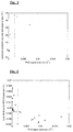
- Figure 3 shows an example of a raw output voltage trace from the PCD 12. The broken horizontal lines show the threshold voltage that is used to define the level of background noise, and the signal first exceeds this level at a time of about 0.9x10 -4 seconds. Thereafter the signal continues to vary significantly outside this threshold voltage.
- the time at which the signal first exceeds the threshold level can be used to determine the distance from the detector to the front of the cavitation bubble cloud, i.e. the closest part of the cavitation cloud to the HIFU transducer 11. This measurement can be repeated for each ultrasound pulse, so that the position of the cavitation cloud can be monitored over time.
- the position of the front of the cavitation cloud varies over time during any exposure to ultrasound.
- the three traces show the distance between the ultrasound transducer 11 and the front of the cavitation cloud over the cavitation period of about 2s in each of three separate exposures of pulsed ultrasound. As can be seen, the distance varies considerably between exposures, and also varies significantly over the course of each exposure.
- the variance of the detector signal is measured, and is generally indicative of the level of cavitation. Variations in the level of cavitation result in variation in the induced temperature rise and the position of the cavitation cloud.
- a test sample such as a phantom or excised tissue
- pulsed ultrasound used to insonate the sample over a test period.
- the temperature of the sample is measured using a thermometer, while the detector signal variance ⁇ 2 is also measured.
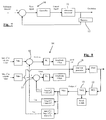
- the controller 14 is arranged to operate on a closed loop control basis.
- the controller 14 is arranged to provide control signals to the ultrasound transducer 11, so as to control the amplitude and other parameters of the ultrasound generated.
- the detector 12 is arranged to sense any cavitation produced, and send sensor signals back to the controller 14.
- the controller is also arranged to receive a reference demand, which may correspond to a value or range of values of a parameter of the sensor signals, to compare the sensor signals, or the appropriate parameter of the sensor signals defined by the reference demand, with the reference demand and to calculate an error, and then to adjust the control signals if the error meets conditions stored in the controller.
- this basic feedback system can take many forms depending on the nature of the detector 12, which can be different from the PCD 12 as described above, on the parameter of the cavitation that is to be controlled, and on the relationship between that parameter and the parameter of the cavitation that can be directly measured, or the parameter of the sensor signals.
- the controller is arranged to receive the voltage signal V from the PCD 12, and includes a data acquisition card (DAQ) 13 which feeds digitized data to a software routine running on a computer, enabling calculation of the variance ⁇ 2 of that voltage signal.
- the controller has stored in it a setpoint range of variance values, defined as maximum and minimum values of the variance ⁇ 2 .
- This setpoint range is based around the target variance value shown in Figures 5 and 6 .
- This setpoint range forms a reference demand, and can be input and updated depending on the nature of the cavitation that is required.
- the controller is arranged to calculate the log of the measured detector signal variance and the log of the max and min setpoint variances, and to compare the log of the measured variance with the logs of the max and min values, and to control the amplitude of the drive signal to the transducer depending on the result.
- the part of the controller 14 that generates the drive signals for the HIFU transducer 11 is referred to as the function generator 18, and this controls the amplitude, as well as any other appropriate parameters, of the ultrasound generated by the HIFU transducer 11. If the measured variance ⁇ 2 is within the desired range between the max and min values, then the function generator 18 that generates the control signal is arranged to keep the amplitude of the drive signal constant.
- a comparator 15 calculates an error e 1 , which is the amount by which it is too high.
- the controller calculates a reduced amplitude, reducing the current amplitude by a correction value, calculated as the product of the error e, and a first gain factor k, which is input to the function generator.
- a separate comparator 17 calculates an error e 2 , which is the amount by which it is too low.
- the controller then calculates an increased amplitude, increasing the current amplitude by a correction value, calculated as the product of the error e 2 and a second gain factor k 2 , which is input to the function generator.
- the function generator 18 therefore alters the amplitude of the control signal to the transducer 11 so as to keep the PCD detector signal variance, and hence the level of cavitation, within the desired range of values.
- FIG. 9 the control system described above can maintain cavitation for an extended test period of, in this case, over 20s.
- the upper line is a plot of PCD signal variance over time for a broadband ultrasound frequency range indicative of inertial cavitation in the system of Figure 8 .
- the lower line is a plot of variance for frequencies corresponding to harmonic emissions indicative of stable cavitation. It can be seen that, while it varies significantly, some level of cavitation is maintained throughout the 20s period. It can also be seen that the variances for the broadband and harmonic frequencies vary in different ways over time. Because they generate ultrasound of different frequency content, the different types of cavitation activity can be detected and controlled separately.
- Figure 10 shows the peak focal pressure, i.e.
- FIG. 11 shows the resulting temperature of the sample through the 20s period. As can be seen this rises up to a target temperature, shown by the broken line, and then fluctuates around that level throughout the 20s period. This shows good control of the tissue temperature which can be used to provide controlled treatment.
- Figure 12 shows how the distance between the front edge of the cavitation cloud and the transducer 11 varies during the test period. In this case the distance decreases steadily throughout the test period, but remains within acceptable limits.
- Figures 13 to 15 show the detector signal variances, the temperature increase, and the distance from cavitation cloud to ultrasound transducer for a pulsed ultrasound signal with a fixed peak focal pressure of 7.3MPa
- Figures 16 to 18 are similar plots for a fixed 10.5MPa peak focal pressure. As can be seen, in each case, the temperature rise starts significantly higher than desired, and is not maintained, falling below the desired level quite quickly.
- the controller of Figure 8 can be modified in various ways to provide further or alternative types of control.
- the position of the cavitation cloud as measured by its distance from the ultrasound transducer, can be used as a control input.
- the response of the controller to that data can be very simple. For example a threshold distance can be defined and, if the distance becomes less than that threshold, the transducer 11 can be switched off and the ultrasound transmission ended, on the assumption that heat is being applied to a region of tissue where it is not desirable.
- a set point range of acceptable values for that distance can be defined, and the control signal amplitude varied so as to maintain the distance within the setpoint range.
- the system can be arranged to control just bubble cloud position, and not the degree of cavitation.
- the target value of the PCD signal variance can be set to zero, or a target range of PCD signal variance set with a low upper limit.
- the system is then arranged to modify or stop the ultrasound transmission when cavitation is detected so as to bring the PCD signal variance back to the target value or range.
- the controller is arranged to measure the detector signal variance for both the broadband range and a range of harmonics of the transducer frequency. It can then monitor variations in the relative magnitudes of those variances which can be used as an indication of changes in the type of cavitation activity.
- the driving signal for the ultrasound transducer can be controlled in response to these changes to control the type of cavitation activity being produced.
- the examples described above rely on varying the amplitude of the driving signal to the ultrasound transducer, and hence the amplitude of the ultrasound waves generated in the subject, other parameters of the driving signal and hence of the ultrasound generated can also be varied by the feedback control.
- the frequency of the ultrasound can be varied, or where the ultrasound is pulsed, the pulse duration, duty cycle, or pulse repetition frequency can be varied.
- two or more transducers can be included in the system. This gives greater control over the position of the cavitation being produced, as the relative amplitudes of the transducers can be controlled to control the focus or centre of the cavitation.
- the setpoint can be determined by varying the drive signals to the ultrasound transducer or transducers so as to produce a variation in the cavitation and hence a variation in the measured parameter, and also measuring a further parameter, such as tissue temperature or other therapeutically desirable bioeffect such as cell permeability, drug diffusion lengthscale, etc, and identifying the setpoint value or range of the measured parameter that corresponds to a desired value of the further parameter.
- tissue temperature or other therapeutically desirable bioeffect such as cell permeability, drug diffusion lengthscale, etc.
- Embodiments of the invention provide both a procedure and the implementation of an adaptive feedback controller that utilizes the signal received from one or several passive cavitation detectors (PCD) to affect the input signal to the therapeutic ultrasound transducer(s) in order to both maintain and localize cavitation activity for prolonged periods of time.
- PCD passive cavitation detectors
- the controller has thus far been implemented in the context of maximizing cavitation-enhanced heating, but the procedures are directly extendable to optimizing other therapeutically desirable bioeffects and could also extend to applications outside the biomedical arena, for example in ultrasound cleaning baths, cavitation control in nuclear reactors, etc.
Landscapes
- Health & Medical Sciences (AREA)
- Life Sciences & Earth Sciences (AREA)
- Engineering & Computer Science (AREA)
- Radiology & Medical Imaging (AREA)
- Animal Behavior & Ethology (AREA)
- Veterinary Medicine (AREA)
- Nuclear Medicine, Radiotherapy & Molecular Imaging (AREA)
- Public Health (AREA)
- General Health & Medical Sciences (AREA)
- Biomedical Technology (AREA)
- Heart & Thoracic Surgery (AREA)
- Medical Informatics (AREA)
- Molecular Biology (AREA)
- Surgery (AREA)
- Physics & Mathematics (AREA)
- Mechanical Engineering (AREA)
- Pathology (AREA)
- Biophysics (AREA)
- Surgical Instruments (AREA)
Claims (9)
- Ein Ultraschallsystem, das einen Signalgeber aufweist, eine Steuerung, die so angeordnet ist, dass sie Steuersignale erzeugt, die dazu dienen, den Signalgeber zu steuern, um auf ein Zielvolumen gerichtete Druckwellen zu erzeugen, und eine Tastvorrichtung, die mindestens einen passiven Druckwellendetektor aufweist, der so angeordnet ist, dass er Druckwellen erfassen kann, die durch Trägheitskavitation im Zielvolumen erzeugt werden, wobei die Steuerung für Folgendes vorgesehen ist:den Empfang der Tastsignale vom Detektorelement;die Errechnung der Position der Kavitation aus den Tastsignalen, der Veränderungen in der Kavitationsmenge und der Veränderungen im Kavitationstyp;die Definition mindestens eines Parameters der Tastsignale und eines Zielbereichs des oder der Parameter;und die Änderung der Steuersignale als Reaktion auf den Parameter oder einen der Parameter, die außerhalb ihres Zielbereichs liegen, um dadurch die Position, Menge und den Typ der Kavitation zu steuern.
- Ein System gemäß Anspruch 1, wobei der mindestens eine Parameter eine Empfangsdauer für die Druckwellen am Druckwellendetektor einschließt, wobei die Steuerung so angeordnet ist, dass sie die Position der Kavitation steuert.
- Ein System gemäß Anspruch 1 oder Anspruch 2, wobei der mindestens eine Parameter den Frequenzgehalt innerhalb eines oder mehrerer Frequenzbänder der Druckwellen, die bei der Kavitation erzeugt und vom Druckwellendetektor erfasst werden, einschließt, wobei die Steuerung so angeordnet ist, dass sie den Typ der Kavitation steuert.
- Ein System gemäß eines der vorhergehenden Ansprüche, wobei der mindestens eine Parameter die Abweichung der Tastsignale einschließt, wobei die Steuerung so angeordnet ist, dass sie die Menge der Kavitation steuert.
- Ein System gemäß Anspruch 4, wobei das Steuersignal ein Antriebssignal mit einer Amplitude ist, der Bereich wird dabei durch eine Höchstabweichung und eine Mindestabweichung definiert und die Steuerung ist so angeordnet, dass sie die Amplitude verringert, wenn ein Messwert der Abweichung größer als die Höchstabweichung ist, und die Amplitude erhöht, wenn der Messwert der Abweichung unter dem Mindestwert liegt.
- Ein System gemäß Anspruch 5, wobei die Steuerung so angeordnet ist, dass sie die Amplitude um einen Korrekturwert verringert, der das Produkt aus einem Fehlerwert und einem ersten Verstärkungsfaktor ist, und die Amplitude um einen Korrekturwert erhöht, der das Produkt aus einem Fehlerwert und einem zweiten Verstärkungsfaktor ist.
- Ein Verfahren zur Installation eines Druckwellen-Steuerungssystems, das die Erzeugung eines Steuersignals aufweist, um einen Druckwellenfühler zu steuern und dadurch Kavitation herzustellen, sowie das Abtasten der Kavitation, unter Verwendung der Tastvorrichtung, die so angeordnet ist, dass sie ein Tastsignal ausgibt, das einen Parameter der Kavitation anzeigt, die Veränderung des Steuersignals, um die Kavitation zu variieren, die Definition eines Abtastparameters des Tastsignals, die Messung eines gesteuerten Parameters der Kavitation, der vom System gesteuert werden muss, die Festlegung wie der Abtastparameter sich bei Veränderungen im gesteuerten Parameter verändert, und die Auswahl eines Zielwertes des Abtastparameters, der einem Zielwert des gesteuerten Parameters entspricht.
- Ein Verfahren gemäß Anspruch 7, wobei die Tastvorrichtung einen Drucksensor aufweist, der so angeordnet ist, dass er die durch die Kavitation erzeugten Druckwellen erfasst.
- Ein Verfahren gemäß Anspruch 8, wobei der gesteuerte Parameter eine Temperatur oder eine Position der Kavitation oder eine Menge des Stofftransports oder eine Messung der thermischen Schädigung oder eine Messung der mechanischen Schädigung, aufgrund der Kavitation, aufweist.
Applications Claiming Priority (2)
| Application Number | Priority Date | Filing Date | Title |
|---|---|---|---|
| GBGB0916634.9A GB0916634D0 (en) | 2009-09-22 | 2009-09-22 | Ultrasound systems |
| PCT/GB2010/051570 WO2011036475A1 (en) | 2009-09-22 | 2010-09-20 | Ultrasound systems |
Publications (2)
| Publication Number | Publication Date |
|---|---|
| EP2480135A1 EP2480135A1 (de) | 2012-08-01 |
| EP2480135B1 true EP2480135B1 (de) | 2016-03-02 |
Family
ID=41327406
Family Applications (1)
| Application Number | Title | Priority Date | Filing Date |
|---|---|---|---|
| EP10768048.0A Active EP2480135B1 (de) | 2009-09-22 | 2010-09-20 | Ultraschallsysteme |
Country Status (5)
| Country | Link |
|---|---|
| US (1) | US9220476B2 (de) |
| EP (1) | EP2480135B1 (de) |
| ES (1) | ES2569508T3 (de) |
| GB (1) | GB0916634D0 (de) |
| WO (1) | WO2011036475A1 (de) |
Families Citing this family (22)
| Publication number | Priority date | Publication date | Assignee | Title |
|---|---|---|---|---|
| US20100069827A1 (en) | 2008-09-12 | 2010-03-18 | Barry Neil Silberg | Pre-Surgical Prophylactic Administration of Antibiotics and Therapeutic Agents |
| US9446227B2 (en) | 2008-09-12 | 2016-09-20 | Sonescence, Inc. | Ultrasonic dispersion of compositions in tissue |
| US9147046B2 (en) * | 2010-04-28 | 2015-09-29 | Empi, Inc. | Systems and methods for modulating pressure wave therapy |
| EP2744570B1 (de) | 2011-09-27 | 2016-08-17 | Koninklijke Philips N.V. | Kavitationsverstärkter hochintensiver fokussierter ultraschall |
| US20140100459A1 (en) | 2012-10-05 | 2014-04-10 | The Regents Of The University Of Michigan | Bubble-induced color doppler feedback during histotripsy |
| US11432900B2 (en) | 2013-07-03 | 2022-09-06 | Histosonics, Inc. | Articulating arm limiter for cavitational ultrasound therapy system |
| US10780298B2 (en) | 2013-08-22 | 2020-09-22 | The Regents Of The University Of Michigan | Histotripsy using very short monopolar ultrasound pulses |
| GB201320413D0 (en) | 2013-11-19 | 2014-01-01 | Isis Innovation | Cavitation-inducing polymeric nanoparticles |
| US9956388B2 (en) | 2014-06-04 | 2018-05-01 | Sonescence, Inc. | Systems and methods for therapeutic agent delivery |
| WO2016210133A1 (en) | 2015-06-24 | 2016-12-29 | The Regents Of The Universtiy Of Michigan | Histotripsy therapy systems and methods for the treatment of brain tissue |
| KR20170076456A (ko) * | 2015-12-21 | 2017-07-04 | 삼성전자주식회사 | 초음파 영상장치 및 초음파 영상장치의 제어방법 |
| WO2018036912A1 (en) * | 2016-08-26 | 2018-03-01 | Koninklijke Philips N.V. | Detection of treatment failure for mild hyperthermia |
| WO2020113083A1 (en) | 2018-11-28 | 2020-06-04 | Histosonics, Inc. | Histotripsy systems and methods |
| JP2023513012A (ja) | 2020-01-28 | 2023-03-30 | ザ リージェンツ オブ ザ ユニバーシティー オブ ミシガン | ヒストトリプシー免疫感作のためのシステムおよび方法 |
| CN116113376A (zh) | 2020-06-18 | 2023-05-12 | 希斯托索尼克斯公司 | 组织摧毁声学和患者耦合系统和方法 |
| JP7789391B2 (ja) | 2020-08-27 | 2025-12-22 | ザ リージェンツ オブ ザ ユニバーシティー オブ ミシガン | ヒストトリプシのための送受信機能を備えた超音波トランスデューサ |
| CN113440167B (zh) * | 2021-06-28 | 2022-06-10 | 南京大学 | 一种基于rf信号的肺部超声信号特征的识别方法 |
| AU2023366591A1 (en) | 2022-10-28 | 2025-04-24 | Histosonics, Inc. | Histotripsy systems and methods |
| EP4389112A1 (de) | 2022-12-23 | 2024-06-26 | Oxsonics Limited | Kavitationsinduzierende biologisch abbaubare polymerteilchen |
| GB202301928D0 (en) * | 2023-02-10 | 2023-03-29 | Oxsonics Ltd | Monitoring drug delivery |
| KR20260003742A (ko) | 2023-04-20 | 2026-01-07 | 히스토소닉스, 인크. | 치료 계획 및 요법을 위한 사용자 인터페이스들 및 작업 흐름들을 포함하는 히스토트립시 시스템들 및 연관된 방법들 |
| KR20250011781A (ko) * | 2023-07-13 | 2025-01-22 | (주)아이엠지티 | 집속 초음파 처리 장치 및 그 방법 |
Family Cites Families (14)
| Publication number | Priority date | Publication date | Assignee | Title |
|---|---|---|---|---|
| US5158071A (en) * | 1988-07-01 | 1992-10-27 | Hitachi, Ltd. | Ultrasonic apparatus for therapeutical use |
| AU1600000A (en) * | 1998-10-28 | 2000-05-15 | Covaris, Inc. | Apparatus and methods for controlling sonic treatment |
| US6508774B1 (en) * | 1999-03-09 | 2003-01-21 | Transurgical, Inc. | Hifu applications with feedback control |
| US6645162B2 (en) * | 2000-12-27 | 2003-11-11 | Insightec - Txsonics Ltd. | Systems and methods for ultrasound assisted lipolysis |
| DE10102317A1 (de) | 2001-01-19 | 2002-08-14 | Hmt Ag | Verfahren und Vorrichtung zur Beaufschlagung des Körpers eines Lebeswesens mit Druckwellen |
| US6770039B2 (en) * | 2001-11-09 | 2004-08-03 | Duke University | Method to reduce tissue injury in shock wave lithotripsy |
| JP4551090B2 (ja) | 2002-02-20 | 2010-09-22 | メディシス テクノロジーズ コーポレイション | 脂肪組織の超音波処理および画像化 |
| US6860852B2 (en) | 2002-10-25 | 2005-03-01 | Compex Medical S.A. | Ultrasound therapeutic device |
| WO2005074365A2 (en) | 2004-02-06 | 2005-08-18 | Technion Research And Development Foundation Ltd. | Localized production of microbubbles and control of cavitational and heating effects by use of enhanced ultrasound |
| CA2604380A1 (en) * | 2005-04-12 | 2006-10-19 | Ekos Corporation | Ultrasound catheter with cavitation promoting surface |
| US20070083120A1 (en) | 2005-09-22 | 2007-04-12 | Cain Charles A | Pulsed cavitational ultrasound therapy |
| US20070265560A1 (en) * | 2006-04-24 | 2007-11-15 | Ekos Corporation | Ultrasound Therapy System |
| WO2009094554A2 (en) * | 2008-01-25 | 2009-07-30 | The Regents Of The University Of Michigan | Histotripsy for thrombolysis |
| GB0820377D0 (en) | 2008-11-07 | 2008-12-17 | Isis Innovation | Mapping and characterization of cavitation activity |
-
2009
- 2009-09-22 GB GBGB0916634.9A patent/GB0916634D0/en not_active Ceased
-
2010
- 2010-09-20 EP EP10768048.0A patent/EP2480135B1/de active Active
- 2010-09-20 US US13/497,470 patent/US9220476B2/en active Active
- 2010-09-20 ES ES10768048.0T patent/ES2569508T3/es active Active
- 2010-09-20 WO PCT/GB2010/051570 patent/WO2011036475A1/en not_active Ceased
Also Published As
| Publication number | Publication date |
|---|---|
| WO2011036475A1 (en) | 2011-03-31 |
| US9220476B2 (en) | 2015-12-29 |
| GB0916634D0 (en) | 2009-11-04 |
| ES2569508T3 (es) | 2016-05-11 |
| US20120259222A1 (en) | 2012-10-11 |
| EP2480135A1 (de) | 2012-08-01 |
Similar Documents
| Publication | Publication Date | Title |
|---|---|---|
| EP2480135B1 (de) | Ultraschallsysteme | |
| US20100318002A1 (en) | Acoustic-Feedback Power Control During Focused Ultrasound Delivery | |
| EP3723856B1 (de) | Steuerung der eigenschaften exogener mittel in mikroblasenvermittelten ultraschallverfahren | |
| US10226646B2 (en) | Optimization and feedback control of HIFU power deposition through the analysis of detected signal characteristics | |
| US8216161B2 (en) | Optimization and feedback control of HIFU power deposition through the frequency analysis of backscattered HIFU signals | |
| Hockham et al. | A real-time controller for sustaining thermally relevant acoustic cavitation during ultrasound therapy | |
| KR20190080967A (ko) | 조직에 초음파원을 연결하는 시스템 및 방법 | |
| Takagi et al. | Enhancement of localized heating by ultrasonically induced cavitation in high intensity focused ultrasound treatment | |
| EP2480136A1 (de) | Ultraschallsysteme | |
| Kyriakou et al. | HIFU-induced cavitation and heating in ex vivo porcine subcutaneous fat | |
| EP2320803B1 (de) | Optimierung und feedback-kontrolle der hifu-energieabscheidung durch analyse von nachgewiesenen signaleigenschaften | |
| CN105054972A (zh) | 一种超声诊疗系统及利用该系统治疗肿瘤的方法 | |
| CN103480092A (zh) | 一种超声能量输出控制装置、方法以及超声治疗设备 | |
| KR101117275B1 (ko) | 초음파를 이용한 지방분해 장치 | |
| CN115382119B (zh) | 脉冲输出的控制方法及治疗仪 | |
| KR20100136144A (ko) | 초음파를 이용한 주름 완화 장치 및 그 방법 | |
| US20090264798A1 (en) | System and method for controlling energy delivery using local harmonic motion | |
| Cui et al. | In vivo hyperthermia effect induced by high-intensity pulsed ultrasound | |
| JPWO2017077605A1 (ja) | 超音波医療装置 | |
| CN113015488A (zh) | 用于谱分析和确定使得能够确保治疗性超声介入的安全性的标记的方法和系统 | |
| Ming-He et al. | Nonlinear effect on focusing gain of a focusing transducer with a wide aperture angle | |
| US20090105617A1 (en) | Non-invasive quantitative body contouring by high intensive focused ultrasound | |
| Yoshizawa et al. | Cavitation detection with subharmonic emissions by low intensity sustaining ultrasound | |
| McLaughlan et al. | A study of cavitation activity in ex vivo tissue exposed to high intensity focused ultrasound | |
| 崔炜程 et al. | In vivo hyperthermia effect induced by high-intensity pulsed ultrasound |
Legal Events
| Date | Code | Title | Description |
|---|---|---|---|
| PUAI | Public reference made under article 153(3) epc to a published international application that has entered the european phase |
Free format text: ORIGINAL CODE: 0009012 |
|
| 17P | Request for examination filed |
Effective date: 20120314 |
|
| AK | Designated contracting states |
Kind code of ref document: A1 Designated state(s): AL AT BE BG CH CY CZ DE DK EE ES FI FR GB GR HR HU IE IS IT LI LT LU LV MC MK MT NL NO PL PT RO SE SI SK SM TR |
|
| DAX | Request for extension of the european patent (deleted) | ||
| REG | Reference to a national code |
Ref country code: DE Ref legal event code: R079 Ref document number: 602010030920 Country of ref document: DE Free format text: PREVIOUS MAIN CLASS: A61B0008000000 Ipc: A61N0007000000 |
|
| GRAP | Despatch of communication of intention to grant a patent |
Free format text: ORIGINAL CODE: EPIDOSNIGR1 |
|
| RIC1 | Information provided on ipc code assigned before grant |
Ipc: A61B 8/00 20060101ALI20150812BHEP Ipc: A61B 17/22 20060101ALI20150812BHEP Ipc: A61B 18/00 20060101ALI20150812BHEP Ipc: A61N 7/00 20060101AFI20150812BHEP Ipc: A61N 7/02 20060101ALI20150812BHEP Ipc: B06B 1/02 20060101ALI20150812BHEP |
|
| INTG | Intention to grant announced |
Effective date: 20150914 |
|
| GRAS | Grant fee paid |
Free format text: ORIGINAL CODE: EPIDOSNIGR3 |
|
| GRAA | (expected) grant |
Free format text: ORIGINAL CODE: 0009210 |
|
| AK | Designated contracting states |
Kind code of ref document: B1 Designated state(s): AL AT BE BG CH CY CZ DE DK EE ES FI FR GB GR HR HU IE IS IT LI LT LU LV MC MK MT NL NO PL PT RO SE SI SK SM TR |
|
| REG | Reference to a national code |
Ref country code: GB Ref legal event code: FG4D |
|
| REG | Reference to a national code |
Ref country code: AT Ref legal event code: REF Ref document number: 777573 Country of ref document: AT Kind code of ref document: T Effective date: 20160315 Ref country code: CH Ref legal event code: EP Ref country code: CH Ref legal event code: NV Representative=s name: BOVARD AG, CH |
|
| REG | Reference to a national code |
Ref country code: IE Ref legal event code: FG4D |
|
| REG | Reference to a national code |
Ref country code: NL Ref legal event code: FP |
|
| REG | Reference to a national code |
Ref country code: DE Ref legal event code: R096 Ref document number: 602010030920 Country of ref document: DE |
|
| REG | Reference to a national code |
Ref country code: ES Ref legal event code: FG2A Ref document number: 2569508 Country of ref document: ES Kind code of ref document: T3 Effective date: 20160511 |
|
| REG | Reference to a national code |
Ref country code: LT Ref legal event code: MG4D |
|
| REG | Reference to a national code |
Ref country code: AT Ref legal event code: MK05 Ref document number: 777573 Country of ref document: AT Kind code of ref document: T Effective date: 20160302 |
|
| PG25 | Lapsed in a contracting state [announced via postgrant information from national office to epo] |
Ref country code: FI Free format text: LAPSE BECAUSE OF FAILURE TO SUBMIT A TRANSLATION OF THE DESCRIPTION OR TO PAY THE FEE WITHIN THE PRESCRIBED TIME-LIMIT Effective date: 20160302 Ref country code: HR Free format text: LAPSE BECAUSE OF FAILURE TO SUBMIT A TRANSLATION OF THE DESCRIPTION OR TO PAY THE FEE WITHIN THE PRESCRIBED TIME-LIMIT Effective date: 20160302 Ref country code: GR Free format text: LAPSE BECAUSE OF FAILURE TO SUBMIT A TRANSLATION OF THE DESCRIPTION OR TO PAY THE FEE WITHIN THE PRESCRIBED TIME-LIMIT Effective date: 20160603 Ref country code: NO Free format text: LAPSE BECAUSE OF FAILURE TO SUBMIT A TRANSLATION OF THE DESCRIPTION OR TO PAY THE FEE WITHIN THE PRESCRIBED TIME-LIMIT Effective date: 20160602 |
|
| REG | Reference to a national code |
Ref country code: CH Ref legal event code: PFA Owner name: OXFORD UNIVERSITY INNOVATION LIMITED, GB Free format text: FORMER OWNER: ISIS INNOVATION LIMITED, GB |
|
| RAP2 | Party data changed (patent owner data changed or rights of a patent transferred) |
Owner name: OXFORD UNIVERSITY INNOVATION LIMITED |
|
| REG | Reference to a national code |
Ref country code: DE Ref legal event code: R082 Ref document number: 602010030920 Country of ref document: DE Representative=s name: SAMSON & PARTNER PATENTANWAELTE MBB, DE Ref country code: DE Ref legal event code: R081 Ref document number: 602010030920 Country of ref document: DE Owner name: OXFORD UNIVERSITY INNOVATION LIMITED, GB Free format text: FORMER OWNER: ISIS INNOVATION LIMITED, SUMMERTOWN, OXFORD, GB Ref country code: DE Ref legal event code: R081 Ref document number: 602010030920 Country of ref document: DE Owner name: OXSONICS LTD., GB Free format text: FORMER OWNER: ISIS INNOVATION LIMITED, SUMMERTOWN, OXFORD, GB |
|
| PG25 | Lapsed in a contracting state [announced via postgrant information from national office to epo] |
Ref country code: AT Free format text: LAPSE BECAUSE OF FAILURE TO SUBMIT A TRANSLATION OF THE DESCRIPTION OR TO PAY THE FEE WITHIN THE PRESCRIBED TIME-LIMIT Effective date: 20160302 Ref country code: LV Free format text: LAPSE BECAUSE OF FAILURE TO SUBMIT A TRANSLATION OF THE DESCRIPTION OR TO PAY THE FEE WITHIN THE PRESCRIBED TIME-LIMIT Effective date: 20160302 Ref country code: PL Free format text: LAPSE BECAUSE OF FAILURE TO SUBMIT A TRANSLATION OF THE DESCRIPTION OR TO PAY THE FEE WITHIN THE PRESCRIBED TIME-LIMIT Effective date: 20160302 Ref country code: LT Free format text: LAPSE BECAUSE OF FAILURE TO SUBMIT A TRANSLATION OF THE DESCRIPTION OR TO PAY THE FEE WITHIN THE PRESCRIBED TIME-LIMIT Effective date: 20160302 Ref country code: SE Free format text: LAPSE BECAUSE OF FAILURE TO SUBMIT A TRANSLATION OF THE DESCRIPTION OR TO PAY THE FEE WITHIN THE PRESCRIBED TIME-LIMIT Effective date: 20160302 |
|
| REG | Reference to a national code |
Ref country code: FR Ref legal event code: PLFP Year of fee payment: 7 |
|
| REG | Reference to a national code |
Ref country code: NL Ref legal event code: HC Owner name: OXFORD UNIVERSITY INNOVATION LIMITED; GB Free format text: DETAILS ASSIGNMENT: VERANDERING VAN EIGENAAR(S), VERANDERING VAN NAAM VAN DE EIGENAAR(S); FORMER OWNER NAME: ISIS INNOVATION LIMITED Effective date: 20160802 |
|
| PG25 | Lapsed in a contracting state [announced via postgrant information from national office to epo] |
Ref country code: EE Free format text: LAPSE BECAUSE OF FAILURE TO SUBMIT A TRANSLATION OF THE DESCRIPTION OR TO PAY THE FEE WITHIN THE PRESCRIBED TIME-LIMIT Effective date: 20160302 Ref country code: IS Free format text: LAPSE BECAUSE OF FAILURE TO SUBMIT A TRANSLATION OF THE DESCRIPTION OR TO PAY THE FEE WITHIN THE PRESCRIBED TIME-LIMIT Effective date: 20160702 |
|
| PG25 | Lapsed in a contracting state [announced via postgrant information from national office to epo] |
Ref country code: SK Free format text: LAPSE BECAUSE OF FAILURE TO SUBMIT A TRANSLATION OF THE DESCRIPTION OR TO PAY THE FEE WITHIN THE PRESCRIBED TIME-LIMIT Effective date: 20160302 Ref country code: SM Free format text: LAPSE BECAUSE OF FAILURE TO SUBMIT A TRANSLATION OF THE DESCRIPTION OR TO PAY THE FEE WITHIN THE PRESCRIBED TIME-LIMIT Effective date: 20160302 Ref country code: RO Free format text: LAPSE BECAUSE OF FAILURE TO SUBMIT A TRANSLATION OF THE DESCRIPTION OR TO PAY THE FEE WITHIN THE PRESCRIBED TIME-LIMIT Effective date: 20160302 Ref country code: CZ Free format text: LAPSE BECAUSE OF FAILURE TO SUBMIT A TRANSLATION OF THE DESCRIPTION OR TO PAY THE FEE WITHIN THE PRESCRIBED TIME-LIMIT Effective date: 20160302 Ref country code: PT Free format text: LAPSE BECAUSE OF FAILURE TO SUBMIT A TRANSLATION OF THE DESCRIPTION OR TO PAY THE FEE WITHIN THE PRESCRIBED TIME-LIMIT Effective date: 20160704 |
|
| REG | Reference to a national code |
Ref country code: DE Ref legal event code: R097 Ref document number: 602010030920 Country of ref document: DE |
|
| PG25 | Lapsed in a contracting state [announced via postgrant information from national office to epo] |
Ref country code: BE Free format text: LAPSE BECAUSE OF FAILURE TO SUBMIT A TRANSLATION OF THE DESCRIPTION OR TO PAY THE FEE WITHIN THE PRESCRIBED TIME-LIMIT Effective date: 20160302 |
|
| PLBE | No opposition filed within time limit |
Free format text: ORIGINAL CODE: 0009261 |
|
| STAA | Information on the status of an ep patent application or granted ep patent |
Free format text: STATUS: NO OPPOSITION FILED WITHIN TIME LIMIT |
|
| PG25 | Lapsed in a contracting state [announced via postgrant information from national office to epo] |
Ref country code: DK Free format text: LAPSE BECAUSE OF FAILURE TO SUBMIT A TRANSLATION OF THE DESCRIPTION OR TO PAY THE FEE WITHIN THE PRESCRIBED TIME-LIMIT Effective date: 20160302 |
|
| 26N | No opposition filed |
Effective date: 20161205 |
|
| PG25 | Lapsed in a contracting state [announced via postgrant information from national office to epo] |
Ref country code: BG Free format text: LAPSE BECAUSE OF FAILURE TO SUBMIT A TRANSLATION OF THE DESCRIPTION OR TO PAY THE FEE WITHIN THE PRESCRIBED TIME-LIMIT Effective date: 20160602 Ref country code: SI Free format text: LAPSE BECAUSE OF FAILURE TO SUBMIT A TRANSLATION OF THE DESCRIPTION OR TO PAY THE FEE WITHIN THE PRESCRIBED TIME-LIMIT Effective date: 20160302 |
|
| PG25 | Lapsed in a contracting state [announced via postgrant information from national office to epo] |
Ref country code: MC Free format text: LAPSE BECAUSE OF FAILURE TO SUBMIT A TRANSLATION OF THE DESCRIPTION OR TO PAY THE FEE WITHIN THE PRESCRIBED TIME-LIMIT Effective date: 20160302 |
|
| REG | Reference to a national code |
Ref country code: IE Ref legal event code: MM4A |
|
| PG25 | Lapsed in a contracting state [announced via postgrant information from national office to epo] |
Ref country code: IE Free format text: LAPSE BECAUSE OF NON-PAYMENT OF DUE FEES Effective date: 20160920 |
|
| REG | Reference to a national code |
Ref country code: DE Ref legal event code: R081 Ref document number: 602010030920 Country of ref document: DE Owner name: OXSONICS LTD., GB Free format text: FORMER OWNER: OXFORD UNIVERSITY INNOVATION LIMITED, OXFORD, OXFORDSHIRE, GB Ref country code: DE Ref legal event code: R082 Ref document number: 602010030920 Country of ref document: DE Representative=s name: SAMSON & PARTNER PATENTANWAELTE MBB, DE Ref country code: DE Ref legal event code: R081 Ref document number: 602010030920 Country of ref document: DE Owner name: OXSONICS LTD., GB Free format text: FORMER OWNER: OXFORD UNIVERSITY INNOVATION LIMITED, OXFORD, GB |
|
| REG | Reference to a national code |
Ref country code: FR Ref legal event code: CA Effective date: 20170710 Ref country code: FR Ref legal event code: CD Owner name: OXFORD UNIVERSITY INNOVATION LIMITED, GB Effective date: 20170710 |
|
| PG25 | Lapsed in a contracting state [announced via postgrant information from national office to epo] |
Ref country code: LU Free format text: LAPSE BECAUSE OF NON-PAYMENT OF DUE FEES Effective date: 20160920 |
|
| REG | Reference to a national code |
Ref country code: CH Ref legal event code: PUE Owner name: OXSONICS LIMITED, GB Free format text: FORMER OWNER: OXFORD UNIVERSITY INNOVATION LIMITED, GB |
|
| REG | Reference to a national code |
Ref country code: GB Ref legal event code: 732E Free format text: REGISTERED BETWEEN 20170907 AND 20170913 |
|
| REG | Reference to a national code |
Ref country code: ES Ref legal event code: PC2A Owner name: OXSONICS LIMITED Effective date: 20171103 |
|
| REG | Reference to a national code |
Ref country code: FR Ref legal event code: PLFP Year of fee payment: 8 |
|
| REG | Reference to a national code |
Ref country code: NL Ref legal event code: PD Owner name: OXSONICS LIMITED; GB Free format text: DETAILS ASSIGNMENT: CHANGE OF OWNER(S), ASSIGNMENT; FORMER OWNER NAME: OXFORD UNIVERSITY INNOVATION LIMITED Effective date: 20171013 |
|
| REG | Reference to a national code |
Ref country code: FR Ref legal event code: TP Owner name: OXSONICS LIMITED, GB Effective date: 20171201 |
|
| PG25 | Lapsed in a contracting state [announced via postgrant information from national office to epo] |
Ref country code: CY Free format text: LAPSE BECAUSE OF FAILURE TO SUBMIT A TRANSLATION OF THE DESCRIPTION OR TO PAY THE FEE WITHIN THE PRESCRIBED TIME-LIMIT Effective date: 20160302 Ref country code: HU Free format text: LAPSE BECAUSE OF FAILURE TO SUBMIT A TRANSLATION OF THE DESCRIPTION OR TO PAY THE FEE WITHIN THE PRESCRIBED TIME-LIMIT; INVALID AB INITIO Effective date: 20100920 |
|
| PG25 | Lapsed in a contracting state [announced via postgrant information from national office to epo] |
Ref country code: MT Free format text: LAPSE BECAUSE OF NON-PAYMENT OF DUE FEES Effective date: 20160930 Ref country code: MK Free format text: LAPSE BECAUSE OF FAILURE TO SUBMIT A TRANSLATION OF THE DESCRIPTION OR TO PAY THE FEE WITHIN THE PRESCRIBED TIME-LIMIT Effective date: 20160302 Ref country code: TR Free format text: LAPSE BECAUSE OF FAILURE TO SUBMIT A TRANSLATION OF THE DESCRIPTION OR TO PAY THE FEE WITHIN THE PRESCRIBED TIME-LIMIT Effective date: 20160302 |
|
| REG | Reference to a national code |
Ref country code: FR Ref legal event code: PLFP Year of fee payment: 9 |
|
| PG25 | Lapsed in a contracting state [announced via postgrant information from national office to epo] |
Ref country code: AL Free format text: LAPSE BECAUSE OF FAILURE TO SUBMIT A TRANSLATION OF THE DESCRIPTION OR TO PAY THE FEE WITHIN THE PRESCRIBED TIME-LIMIT Effective date: 20160302 |
|
| REG | Reference to a national code |
Ref country code: GB Ref legal event code: 732E Free format text: REGISTERED BETWEEN 20211111 AND 20211117 |
|
| PGFP | Annual fee paid to national office [announced via postgrant information from national office to epo] |
Ref country code: NL Payment date: 20250704 Year of fee payment: 16 |
|
| REG | Reference to a national code |
Ref country code: CH Ref legal event code: U11 Free format text: ST27 STATUS EVENT CODE: U-0-0-U10-U11 (AS PROVIDED BY THE NATIONAL OFFICE) Effective date: 20251001 |
|
| PGFP | Annual fee paid to national office [announced via postgrant information from national office to epo] |
Ref country code: DE Payment date: 20250702 Year of fee payment: 16 |
|
| PGFP | Annual fee paid to national office [announced via postgrant information from national office to epo] |
Ref country code: IT Payment date: 20250825 Year of fee payment: 16 |
|
| PGFP | Annual fee paid to national office [announced via postgrant information from national office to epo] |
Ref country code: GB Payment date: 20250703 Year of fee payment: 16 |
|
| PGFP | Annual fee paid to national office [announced via postgrant information from national office to epo] |
Ref country code: FR Payment date: 20250708 Year of fee payment: 16 |
|
| PGFP | Annual fee paid to national office [announced via postgrant information from national office to epo] |
Ref country code: CH Payment date: 20251001 Year of fee payment: 16 |
|
| PGFP | Annual fee paid to national office [announced via postgrant information from national office to epo] |
Ref country code: ES Payment date: 20251016 Year of fee payment: 16 |