EP2479867A1 - Power distribution system - Google Patents
Power distribution system Download PDFInfo
- Publication number
- EP2479867A1 EP2479867A1 EP10816756A EP10816756A EP2479867A1 EP 2479867 A1 EP2479867 A1 EP 2479867A1 EP 10816756 A EP10816756 A EP 10816756A EP 10816756 A EP10816756 A EP 10816756A EP 2479867 A1 EP2479867 A1 EP 2479867A1
- Authority
- EP
- European Patent Office
- Prior art keywords
- power
- appliances
- appliance
- secondary battery
- power source
- Prior art date
- Legal status (The legal status is an assumption and is not a legal conclusion. Google has not performed a legal analysis and makes no representation as to the accuracy of the status listed.)
- Granted
Links
Images


Classifications
-
- H—ELECTRICITY
- H02—GENERATION; CONVERSION OR DISTRIBUTION OF ELECTRIC POWER
- H02J—ELECTRIC POWER NETWORKS; CIRCUIT ARRANGEMENTS OR SYSTEMS FOR SUPPLYING OR DISTRIBUTING ELECTRIC POWER; SYSTEMS FOR STORING ELECTRIC ENERGY
- H02J1/00—Circuit arrangements for DC mains or DC distribution networks
- H02J1/14—Balancing load and power generation in DC networks
-
- H—ELECTRICITY
- H01—ELECTRIC ELEMENTS
- H01M—PROCESSES OR MEANS, e.g. BATTERIES, FOR THE DIRECT CONVERSION OF CHEMICAL ENERGY INTO ELECTRICAL ENERGY
- H01M10/00—Secondary cells; Manufacture thereof
- H01M10/42—Methods or arrangements for servicing or maintenance of secondary cells or secondary half-cells
- H01M10/44—Methods for charging or discharging
-
- H—ELECTRICITY
- H01—ELECTRIC ELEMENTS
- H01M—PROCESSES OR MEANS, e.g. BATTERIES, FOR THE DIRECT CONVERSION OF CHEMICAL ENERGY INTO ELECTRICAL ENERGY
- H01M10/00—Secondary cells; Manufacture thereof
- H01M10/42—Methods or arrangements for servicing or maintenance of secondary cells or secondary half-cells
- H01M10/46—Accumulators structurally combined with charging apparatus
- H01M10/465—Accumulators structurally combined with charging apparatus with solar battery as charging system
-
- H—ELECTRICITY
- H01—ELECTRIC ELEMENTS
- H01M—PROCESSES OR MEANS, e.g. BATTERIES, FOR THE DIRECT CONVERSION OF CHEMICAL ENERGY INTO ELECTRICAL ENERGY
- H01M10/00—Secondary cells; Manufacture thereof
- H01M10/42—Methods or arrangements for servicing or maintenance of secondary cells or secondary half-cells
- H01M10/48—Accumulators combined with arrangements for measuring, testing or indicating the condition of cells, e.g. the level or density of the electrolyte
-
- Y—GENERAL TAGGING OF NEW TECHNOLOGICAL DEVELOPMENTS; GENERAL TAGGING OF CROSS-SECTIONAL TECHNOLOGIES SPANNING OVER SEVERAL SECTIONS OF THE IPC; TECHNICAL SUBJECTS COVERED BY FORMER USPC CROSS-REFERENCE ART COLLECTIONS [XRACs] AND DIGESTS
- Y02—TECHNOLOGIES OR APPLICATIONS FOR MITIGATION OR ADAPTATION AGAINST CLIMATE CHANGE
- Y02E—REDUCTION OF GREENHOUSE GAS [GHG] EMISSIONS, RELATED TO ENERGY GENERATION, TRANSMISSION OR DISTRIBUTION
- Y02E60/00—Enabling technologies; Technologies with a potential or indirect contribution to GHG emissions mitigation
- Y02E60/10—Energy storage using batteries
Definitions
- the present invention relates to a power distribution system.
- DC Direct Current
- a secondary battery charged with a nighttime power of the commercial power source or a surplus power of a distributed power source such as a solar cell, commercial power source, as a source for supplying power to the appliances For example, an electric bill can be lowered by charging the secondary battery at low cost either using nighttime power in which the electricity rate of the commercial power source is low, or using electric power generated by the solar cell, and then operating the appliances using the power charged in the secondary battery. Further, in the daytime, the electric bill can be lowered by operating the appliances using both the secondary battery and the solar cell.
- the appliances since the residual capacity of the secondary battery or the amount of power generated by the solar cell varies, it is difficult to correspondingly operate the appliances depending on the power consumption thereof using only the DC power source. In this case, the appliances must be operated with the commercial power source together with the DC power source. Since the electricity rate of the commercial power source is high during the daytime or the like, using the commercial power source together with the DC power source is not economical due to the increased cost. Further, a user is incapable of determining an appliance that can be operated with the current residual capacity of the DC power source, and has a difficulty efficiently operating the appliance using the power of the DC power source.
- the present invention has been made keeping in mind the above problems occurring in the prior art, and the present invention provides a power distribution system, which can efficiently and economically use the power of a DC power source to operate the appliances.
- a power distribution system including: a direct current (DC) power source; an appliance selection unit for selecting one or more appliances that can be operated with an available power of the DC power source; and a display unit for displaying results of selection by the appliance selection unit.
- DC direct current
- the power distribution system may further include: a power supply unit for supplying power to a plurality of appliances using a power supplied from the DC power source; an available power detection unit for detecting an amount of power that can be supplied from the DC power source; and a power information storage unit for storing information about a power consumption of each appliance, wherein the DC power source includes at least one of a secondary battery and a solar cell, and wherein the appliance selection unit selects one or more appliances that can be operated with the available power of the DC power source, based on the available power of the DC power source and the information about the power consumption of each appliance.
- a user sets the appliances to be used, by referring to the results of the selection of appliances that can be operated with the DC power source, so that it is possible to effectively use the power of the DC power source without using power supplied from the commercial power source if possible, thus efficiently and economically using the power of the DC power source when the appliances are operated.
- the DC power source may include only the secondary battery, the available power detection unit detects a residual capacity of the secondary battery, and the appliance selection unit selects one or more appliances that can be operated with the residual capacity of the secondary battery, based on the residual capacity of the secondary battery and the information about the power consumption of each appliance.
- the user sets the appliances to be used, by referring to the results of selecting those appliances that can be operated with the residual capacity of the secondary battery, so that it is possible to effectively use the power charged in the secondary battery without using power supplied from the commercial power source whenever possible, thus efficiently and economically using the power charged in the secondary battery to operate the appliances.
- the DC power source may include the secondary battery and the solar cell
- the available power detection unit detects a residual capacity of the secondary battery and a power generated by the solar cell
- the appliance selection unit selects one or more appliances that can be operated with the residual capacity of the secondary battery and the power generated by the solar cell, based on a sum of the residual capacity of the secondary battery and the power generated by the solar cell and the information about the power consumption of each appliance.
- the user sets the appliances to be used, by referring to the results of the selection of appliances that can be operated with the residual capacity of the secondary battery and the power generated by the solar cell, so that it is possible to effectively use the power charged in the secondary battery and the power generated by the solar cell without using the power supplied from the commercial power source if possible, thus efficiently and economically using the power charged in the secondary battery and the power generated by the solar cell when the appliances are operated.
- the appliance selection unit may select appliances, each of which can be operated with the available power of the DC power source.
- the user determines whether each appliance can be operated with the DC power source, by referring to the results of selecting those appliances that can be operated with the DC power source.
- the display unit may display appliances selected by the appliance selection unit in descending order of power consumption.
- an appliance located at an upper position in the list is an appliance that can be efficiently used using the DC power source.
- the power distribution system may further include a manipulation unit for allowing a user to designate a plurality of appliances, wherein the appliance selection unit selects, from the appliances designated by the manipulation unit, a combination of appliances that can be operated with the available power of the DC power source.
- a manipulation unit for allowing a user to designate a plurality of appliances, wherein the appliance selection unit selects, from the appliances designated by the manipulation unit, a combination of appliances that can be operated with the available power of the DC power source.
- the user can conveniently use the appliances because the user does not need to personally consider a combination of appliances to be used.
- the appliance selection unit may select all combinations of appliances that can be operated with the available power of the DC power source.
- a user refers to all combinations of appliances that can be operated with the DC power sources, thus increasing the number of selection items required when setting the appliances to be used.
- the appliance selection unit may select, from the combinations of appliances that can be operated with the available power of the DC power source, a combination of appliances of which a sum of power consumption is highest.
- the DC power source can be used as effectively as possible.
- the power distribution system may further include a proposal unit for creating a proposal that appliances, which are not selected by the appliance selection unit as the appliances that can be operated with the available power of the DC power source, be operated with night-time power of the commercial power source, and outputting the proposal to the display unit, wherein the display unit displays the proposal.
- a proposal unit for creating a proposal that appliances, which are not selected by the appliance selection unit as the appliances that can be operated with the available power of the DC power source, be operated with night-time power of the commercial power source, and outputting the proposal to the display unit, wherein the display unit displays the proposal.
- advice provided regarding the use of appliances that are not selected is also displayed, thus allowing the user to more conveniently use appliances.
- the information about the power consumption of each appliance, stored in the power information storage unit is information generated based on a history of power consumed when each appliance is operated.
- the power information storage unit stores power consumption information calculated based on the actual operations of the appliances, and thus accuracy in the selection of appliances by the appliance selection unit is improved.
- a power distribution system in accordance with the present embodiment is mainly used in a house, and includes an AC distribution board 1 to which AC power supply lines Wa for supplying power to AC appliances La driven by an AC power are connected, and a DC distribution board 2 to which DC power supply lines Wd for supplying power to DC appliances Ld driven by a DC power are connected, as shown in Fig. 1 .
- a commercial power source AC is used as the AC power source
- at least one of a solar cell 3 and a secondary battery 5 is used as the DC power source.
- the AC appliances La and the DC appliances Ld do not need to be distinguished from each other, they are designated as appliances L.
- a detached house is assumed and described as the building to which the present invention is applied, the application of the technical spirit of the present invention to buildings, such as a multiple dwelling house, an office, a shopping district, or a plant, is not intended to be excluded.
- the AC distribution board 1 to which the AC power supply lines Wa are connected is supplied with AC power from the commercial power source AC and from the solar cell 3 that is a distributed power source via a power conditioner 4.
- the AC distribution board 1 includes a main breaker (not shown), a plurality of branch breakers (not shown), switches, and so forth, and supplies AC power to the AC power supply lines Wa branched from the load side of the branch breakers, and to an AC connection line W1.
- the power conditioner 4 has the function of converting DC power generated by the solar cell 3 into AC power and adjusting an output frequency and an output voltage to connect to the commercial power source AC (grid).
- the DC distribution board 2 to which the DC power supply lines Wd are connected is supplied with AC power from the AC distribution board 1 via the AC connection line W1, and is provided with a converter 2a for converting the AC power into DC power of a desired voltage.
- the converter 2a is an AC-DC conversion device, and the output of the converter 2a is supplied to the branched DC power supply lines Wd via a plurality of circuit protectors, switches, and so forth (not shown) that are included in the board.
- the DC distribution board 2 includes a charger/discharger 2b connected between the output of the converter 2a and the secondary battery 5 and configured to perform the charging/discharging of the secondary battery 5.
- the control of charging by the charger/discharger 2b is performed such that surplus power of the DC power supplied by the converter 2a to the DC power supply lines Wd is charged in the secondary battery 5.
- the output voltage of the secondary battery 5 is adjusted by the charger/discharger 2b and is then supplied together with the output of the converter 2a to the DC power supply lines Wd.
- the DC power output from the converter 2a and the secondary battery 5 is also supplied to an inverter 6 via a DC connection line W2.
- the inverter 6 is a DC-AC conversion device having the function of adjusting an output frequency and an output voltage to connect to the commercial power source AC, and is configured to convert DC power into AC power and supply the AC power to the AC power supply lines Wa via the branch breakers of the AC distribution board 1.
- Such a power distribution system is configured such that the commercial power source AC includes the AC power source and the DC power source includes the solar cell 3 and the secondary battery. Further, the AC distribution board 1 serves as an AC power supply means for supplying AC power from the AC power supply lines Wa to the plurality of AC appliances La using the power supplied from the individual power sources and the DC distribution board 2 serves as a DC power supply means for supplying DC power from the DC power supply lines Wd to the plurality of DC appliances Ld using the power supplied from the individual power sources.
- a control device 7 controls power distribution in which a main power source is switched depending on the status of each power source (that is, the control of power distribution that varies the ratio of output from the respective power sources).
- the control device 7 monitors power supplied from the commercial power source AC, the amount of power generated by the solar cell 3, the residual capacity of the secondary battery 5, the AC power supplied from the AC distribution board 1 to the AC power supply lines Wa, and the DC power supplied from the DC distribution board 2 to the DC power supply lines Wd.
- the control device 7 controls the converter 2a, the charger/discharger 2b, the inverter 6, switches accommodated in the AC distribution board 1 and the DC distribution board 2 and so forth, and controls the transfer of power between the AC distribution board 1 and the DC distribution board 2.
- the main power source includes a source for supplying most of power to certain power supply lines compared to other power sources, as well as a source for supplying 100% of power to the certain power supply lines.
- the control device 7 controls power distribution so that power is supplied to individual appliances L using only power charged in the secondary battery 5 .
- the secondary battery 5 is charged by the converter 2a and the charger/discharger 2b using power generated by the solar cell 3 in the daytime, or using power supplied from the commercial power source AC (nighttime power) during a time span in which the electricity rate is low (for example, a time span of 22 p.m. to 7 a.m.).
- the control device 7 controls power distribution so that power is supplied to the individual appliances L using only the power charged in the secondary battery 5 if possible, during a time span in which the electricity rate of the commercial power source AC is high (for example, the time span of 7 a.m.
- the DC appliances Ld on the DC power supply lines Wd are operated with the power charged in the secondary battery 5, and the AC appliances La on the AC power supply lines Wa are operated with the power charged in the secondary battery 5 via the inverter 6.
- the secondary battery 5 becomes the main power source, the amount of power supplied from the commercial power source AC becomes zero, and all of the power generated by the solar cell 3 is used to charge the secondary battery 5.
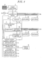
- the control device 7 includes a residual capacity detection unit 7a (available power detection means), a power information storage unit 7b, an appliance selection unit 7c, a list creation unit 7d, and a manipulation unit 7e, and is configured to present to the user a list of appliances L that can be operated with the current residual capacity of the secondary battery 5 (the available power of the DC power source) by performing the operations shown in the flowchart of Fig. 2 .
- a residual capacity detection unit 7a available power detection means
- a power information storage unit 7b an appliance selection unit 7c
- a list creation unit 7d the available power of the DC power source
- the residual capacity detection unit 7a detects the residual capacity (Wh) of the secondary battery 5 (step S2). Further, the power information storage unit 7b stores information about the power consumption of each appliance L, and this power consumption information is configured in the form of an appliance table TB in which the names, power consumption (W), used time (minutes), and electric energy (Wh) of appliances L are listed, as shown in Fig. 3 .
- power consumption (W), used time (minutes), and electric energy (Wh) are the values in a standard use.
- the appliance selection unit 7c refers to the appliance table TB of the power information storage unit 7b (step S3), and then compares the residual capacity of the secondary battery 5 with the power consumption of each appliance L listed in the appliance table TB. Thereafter, the appliance selection unit 7c selects corresponding appliances L of which power consumption is equal to or less than the residual capacity of the secondary battery 5 from the appliance table TB as available appliances (step S4). In the processing of appliance selection at step S4, the appliances L in the appliance table TB are classified as AC appliances La or DC appliances Ld.
- the list creation unit 7d creates a available appliance list presenting appliances L that are selected by the appliance selection unit 7c (step S5), and also creates an unavailable appliance list presenting appliances L that are excluded from the selection by the appliance selection unit 7c (step S6). Further, the list creation unit 7d outputs the available appliance list and the unavailable appliance list, together with the residual capacity information of the secondary battery 5, to a display device 8 that is either provided near the control device 7 or integrated with the control device 7 (step S7).
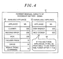
- the display device 8 displays the current residual capacity X1 of the secondary battery 5, a available appliance list X2 in which the names and power consumptions of appliances that can be operated with the current residual capacity of the secondary battery 5 are listed, and an unavailable appliance list X3 in which the names and power consumptions of appliances that cannot be operated with the current residual capacity of the secondary battery 5 are listed.
- the user determines whether each appliance is available or unavailable with the residual capacity of the secondary battery 5 by referring to the available appliance list X2 and sets the appliances L to be used.
- the available appliance list X2 the individual appliances L are indicated in descending order of power consumption. The user can easily recognize that an appliance L located at the upper position of the list is an appliance that can be efficiently used using the residual capacity of the secondary battery 5.
- the list creation unit 7d may create information proposing that, at the time of using appliances L included in the unavailable appliance list X3, the appliances L be operated with the night-time power of the commercial power source AC in which the electricity rate is low, and may output the proposal to the display device 8. As shown in Fig. 4 , the proposal X4 is displayed near the unavailable appliance list X3.
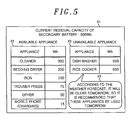
- a means for accessing a network such as the Internet, is provided in the control device 7, and is configured to obtain information about a weather forecast from a server on the Internet.
- the list creation unit 7d may create information proposing that in relation with the use of a washing machine included in the unavailable appliance list, the washing machine be used tomorrow (the next day) on which it is forecasted that the weather will be clear, and may output the proposal to the display device 8. As shown in Fig. 5 , the proposal X5 is displayed near the unavailable appliance list X3.
- control device 7 controls power distribution so that power is supplied to individual appliances L using only the power charged in the secondary battery 5 when a power failure occurs on the commercial power source AC.
- the display device 8 displays the current residual capacity X1 of the secondary battery 5, the available appliance list X2, and the unavailable appliance list X3, similarly to the above case. Further, even in the case of a power failure, it is possible to effectively use the power charged in the secondary battery 5.
- control of power distribution performed by the control device 7 includes a mode in which power is supplied to the individual appliances L by using the commercial power source AC as the main power source, or a mode in which power is supplied to the individual appliances L using together the commercial power source AC, the solar cell 3, and the secondary battery 5, in addition to a mode in which power is supplied to the individual appliances L using only the power charged in the secondary battery 5, as described above, thus enabling the modes to be suitably switched depending on the states or times of the respective power sources.
- Fig. 1 The power distribution system in the present embodiment is shown in Fig. 1 , similarly to embodiment 1, and the same reference numerals are assigned to the same components, and thus a description thereof will be omitted.
- control device 7 controls power distribution so that during the daytime in which the electricity rate of the commercial power source AC is high (for example, the time span of 7 a.m. to 22 p.m.), power is supplied to individual appliances L using only the power charged in the secondary battery 5 if possible.
- the control device 7 performs the operations shown in the flowchart of Fig. 6 and then creates a list that presents to the user a combination of appliances L that can be operated with the current residual capacity of the secondary battery 5 (the available power of the DC power source).
- step S11 when the user manipulates the manipulation unit 7e to make a list presentation request, information about a list of appliances scheduled to be used is output to the display device 8 that is provided near the control device 7 or integrated with the control device 7 (step S11).
- a list X10 of appliances scheduled to be used is displayed in which the names and power consumption of the appliances with check boxes are listed, as shown in Fig. 7 .
- the user designates appliances scheduled to be used by inserting check marks into check boxes corresponding to one or more appliances L desired to be used, and outputs the results of the designation to the control device 7 (step S12).
- the residual capacity detection unit 7a detects the residual capacity (Wh) of the secondary battery 5 (step S13). Further, the power information storage unit 7b stores information about the power consumption of each appliance L and this power consumption information is configured in the form of an appliance table TB in which the names, power consumption (W), used time (minutes), and electric energy (Wh) are listed, as shown in Fig. 3 .
- the power consumption (W), used time (minutes), and electric energy (Wh) are the values used in a standard use.
- the appliance selection unit 7c derives all of the combinations of the appliances scheduled to be used, refers to the appliance table TB of the power information storage unit 7b (step S14), compares the residual capacity of the secondary battery 5 with the power consumption of each combination of appliances scheduled to be used (the sum of the power consumption of the combined appliances L), extracts each combination of appliances L of which the power consumption is equal to or less than the residual capacity of the secondary battery 5, and then selects a combination having the highest power consumption from the extracted combinations (step S15).
- the residual capacity of the secondary battery 5 is 1000 Wh
- five appliances that is, a dish washer, a rice cooker, a trouser press, a dryer, and a mobile phone charger
- a combination of the dish washer (900 Wh), the trouser press (75 W), and the mobile phone charger (15 W) (the sum of the power consumption is 990 Wh) is extracted as the combination of which the sum of the power consumption is equal to or less than 1000 Wh and is the highest.
- the rice cooker and the dryer scheduled to be used are excluded from the combination.
- the list creation unit 7d creates a available appliance list that presents the combinations of the appliances L selected by the appliance selection unit 7c (step S16), and also creates an unavailable appliance list that presents appliances L excluded from the combinations of appliances selected by the appliance selection unit 7c (step S17). Further, the list creation unit 7d outputs the available appliance list and the unavailable appliance list, together with the residual capacity information of the secondary battery 5, to the display device 8 (step S18).
- the display device 8 displays the current residual capacity X11 of the secondary battery 5, a available appliance list X12 in which the names and the power consumption of appliances combined to be available with the current residual capacity of the secondary battery 5 are listed, and an unavailable appliance list X13 in which the names and power consumption of appliances excluded from the combination of appliances selected by the appliance selection unit 7c are listed.
- the user determines the appliances L to be used with reference to the combination of appliances L that are recommended by the available appliance list X12, so that it is possible to effectively use the power charged in the secondary battery 5, without using the power supplied from the commercial power source AC if possible, during the daytime in which the electricity rate is high, thus efficiently and economically using the power charged in the secondary battery 5 when the appliances L are operated. Furthermore, the user does not need to personally consider a combination of appliances L to be used, thus improving convenience of use.
- a combination of appliances L of which the sum of the power consumption is the highest is presented to the user, thus enabling the power charged in the secondary battery 5 to be used as effectively as possible.
- the individual appliances L are displayed in descending order of power consumption, and the user can easily recognize that an appliance L located at an upper position in the list is an appliance that can be efficiently used using the current residual capacity of the secondary battery 5.
- the list creation unit 7d may create information proposing that, in relation with the use of appliances included in the unavailable appliance list X13, the appliances be operated with nighttime power of the commercial power source AC in which the electricity rate is low, and may output the proposal to the display device 8. As shown in Fig. 8 , the proposal X14 is displayed near the unavailable appliance list X13.
- an advice is provided regarding the use of appliances L included in the unavailable appliance list X3 is displayed, thus allowing the user to more conveniently use the appliances.
- a means for accessing a network such as the Internet may be provided in the control device 7, and a proposal based on information acquired from a server on the Internet may be displayed.
- control device 7 controls power distribution so that power is supplied to individual appliances L using only the power charged in the secondary battery 5 when a power failure occurs on the commercial power source AC.
- the display device 8 displays the current residual capacity X11 of the secondary battery 5, a available appliance list X12, and an unavailable appliance list X13, similarly to the above case. Therefore, even in the case of a power failure, it is possible to effectively use the power charged in the secondary battery 5.
- the appliance selection unit 7c may extract each combination of appliances L of which the power consumption is equal to or less than the residual capacity of the secondary battery 5 from the appliances scheduled to be used after step S15, and may select all extracted combinations.
- the list creation unit 7d creates a available appliance list that presents all combinations of the appliances L selected by the appliance selection unit 7c and the display device 8 displays the list. Therefore, the number of selection items required when the user determines the appliances L to be used increases by referring to all combinations of appliances L recommended on the available appliance list.
- FIG. 9 A power distribution system in accordance with the present embodiment is shown in Fig. 9 , and the same reference numerals are assigned to components identical to those of embodiments 1 and 2, and thus a detailed description thereof will be omitted.
- a control device in accordance with the present embodiment includes a power history storage unit 7f and a power information generation unit 7g.
- the power history storage unit 7f acquires information about power consumption when each appliance L is actually operated (or information about power consumption variation over time) from the appliances L, and stores the history of power consumption when each appliance L is operated once.
- the power information generation unit 7g calculates the average of the power consumption of individual appliances L when the individual appliances L are operated once, by referring to the power history storage unit 7f, and stores the results of the calculation in the power information storage unit 7b. That is, the power information storage unit 7b stores the power consumption information calculated based on the actual operations of the appliances L, and thus the accuracy of the selection of appliances by the appliance selection unit 7c is improved.
- the power information generation unit 7g may extract the maximal value of the power consumption when the individual appliances L are operated once, by referring to the power history storage unit 7f, and may store the results of the extraction in the power information storage unit 7b.
- the control device 7 controls power distribution so that power is supplied to individual appliances L using only the power charged in the secondary battery 5 during a time span in which the electricity rate of the commercial power source AC is high (for example, the time span of 7 a.m. to 22 p.m.) or in the case of the commercial power source AC experiencing a power failure. All the power generated by the solar cell 3 is used to charge the secondary battery 5. That is, the only DC power source that is used is the secondary battery 5.
- the configuration of the power distribution system in accordance with the present embodiment is similar to that of embodiment 1, but the control device 7 controls power distribution so that power is supplied to the individual appliances L using both the power charged in the secondary battery 5 and the power generated by the solar cell 3 during the time span in which the electricity rate of the commercial power source AC is high or in the case of the commercial power source AC experiencing a power failure. Only surplus power that is not consumed by the appliances L is charged in the secondary battery 5. That is, the DC power source that is used includes both the secondary battery 5 and the solar cell 3.
- the secondary battery 5 is primarily charged with power supplied from the commercial power source AC (nighttime power) via the converter 2a and the charger/discharger 2b during the time span in which the electricity rate is low (for example, the time span of 22 p.m. to 7 a.m.). Further, the control device 7 controls power distribution so that power is supplied to individual appliances L using both the power charged in the secondary battery 5 and the power generated by the solar cell 3 if possible during the time span in which the electricity rate of the commercial power source AC is high. DC appliances Ld on DC power supply lines Wd are operated with both the power charged in the secondary battery 5 and the generated power of the solar cell 3 via the power conditioner 4 and the converter 2a.
- DC appliances Ld on DC power supply lines Wd are operated with both the power charged in the secondary battery 5 and the generated power of the solar cell 3 via the power conditioner 4 and the converter 2a.
- AC appliances La on AC power supply lines Wa are operated with both the charged power of the secondary battery 5 via the inverter 6 and the generated power of the solar cell 3 via the power conditioner 4.
- the secondary battery 5 and the solar cell 3 may be the main power sources, the amount of power supplied from the commercial power source AC becomes zero, and only surplus power that is not supplied to the appliances L, of the power generated by the solar cell 3, is used to charge the secondary battery 5.
- control device 7 presents to the user a list of appliances L that can be operated with the current residual capacity of the secondary battery 5 and the power generated by the solar cell 3 (the available power of the DC power source).
- the residual capacity detection unit 7a detects the residual capacity (Wh) of the secondary battery 5 and the amount of power (Wh) generated by the solar cell 3.
- the appliance selection unit 7c compares the sum of the residual capacity of the secondary battery 5 and the power generated by the solar cell 3 with the power consumption of each appliance L in the appliance table TB, with reference to the appliance table TB of the power information storage unit 7b, and selects each appliance L of which the power consumption is equal to or less than the sum of the residual capacity of the secondary battery 5 and the power generated by the solar cell 3 from the appliance table TB as available appliances.
- the list creation unit 7d creates a available appliance list that presents appliances L selected by the appliance selection unit 7c and an unavailable appliance list that presents appliances L excluded from the selection by the appliance selection unit 7c.
- the list creation unit 7d outputs the available appliance list and the unavailable appliance list, together with information about the residual capacity of the secondary battery 5 and the amount of power generated by the solar cell 3, to the display device 8 that is provided near the control device 7 or integrated with the control device 7.
- the display device 8 displays of the information and the lists.
- the user sets the appliances L to be used by referring to the available appliance list, so that it is possible to effectively use the power charged in the secondary battery 5 and the power generated by the solar cell 3, without using the power supplied from the commercial power source AC if possible, during the daytime in which the electricity rate is high, thus efficiently and economically using the power charged in the secondary battery 5 and the power generated by the solar cell 3 when the appliances L are operated.
- control device 7 controls power distribution so that power is supplied to individual appliances L using the power charged in the secondary battery 5 and the power generated by the solar cell 3 when the commercial power source AC experiences a power failure.
- the display device 8 displays information about the current residual capacity of the secondary battery 5 and the amount of power generated by the solar cell 3, the available appliance list, and the unavailable appliance list, similarly to the above case. Further, even in the case of a power failure, it is possible to effectively use the power charged in the secondary battery 5 and the power generated by the solar cell 3.
Landscapes
- Engineering & Computer Science (AREA)
- Manufacturing & Machinery (AREA)
- Chemical & Material Sciences (AREA)
- Chemical Kinetics & Catalysis (AREA)
- Electrochemistry (AREA)
- General Chemical & Material Sciences (AREA)
- Life Sciences & Earth Sciences (AREA)
- Sustainable Development (AREA)
- Sustainable Energy (AREA)
- Power Engineering (AREA)
- Charge And Discharge Circuits For Batteries Or The Like (AREA)
- Secondary Cells (AREA)
- Supply And Distribution Of Alternating Current (AREA)
- Direct Current Feeding And Distribution (AREA)
Abstract
Description
- The present invention relates to a power distribution system.
- There is a power distribution system that is provided with a Direct Current (DC) power source, such as a solar cell which generates power using solar light in the daytime and a secondary battery which is charged by a commercial power source or a distributed power source such as the solar cell, and that uses both DC power from the DC power source and the commercial power source to operate home electric appliances (for example, see Japanese Patent Application Publication No.
2009-178025 - In such a power distribution system, it may be more economical to use a secondary battery charged with a nighttime power of the commercial power source or a surplus power of a distributed power source such as a solar cell, commercial power source, as a source for supplying power to the appliances. For example, an electric bill can be lowered by charging the secondary battery at low cost either using nighttime power in which the electricity rate of the commercial power source is low, or using electric power generated by the solar cell, and then operating the appliances using the power charged in the secondary battery. Further, in the daytime, the electric bill can be lowered by operating the appliances using both the secondary battery and the solar cell.
- However, since the residual capacity of the secondary battery or the amount of power generated by the solar cell varies, it is difficult to correspondingly operate the appliances depending on the power consumption thereof using only the DC power source. In this case, the appliances must be operated with the commercial power source together with the DC power source. Since the electricity rate of the commercial power source is high during the daytime or the like, using the commercial power source together with the DC power source is not economical due to the increased cost. Further, a user is incapable of determining an appliance that can be operated with the current residual capacity of the DC power source, and has a difficulty efficiently operating the appliance using the power of the DC power source.
- The present invention has been made keeping in mind the above problems occurring in the prior art, and the present invention provides a power distribution system, which can efficiently and economically use the power of a DC power source to operate the appliances.
- In accordance with one aspect of the present invention, there is provided with a power distribution system including: a direct current (DC) power source; an appliance selection unit for selecting one or more appliances that can be operated with an available power of the DC power source; and a display unit for displaying results of selection by the appliance selection unit.
- The power distribution system may further include: a power supply unit for supplying power to a plurality of appliances using a power supplied from the DC power source; an available power detection unit for detecting an amount of power that can be supplied from the DC power source; and a power information storage unit for storing information about a power consumption of each appliance, wherein the DC power source includes at least one of a secondary battery and a solar cell, and wherein the appliance selection unit selects one or more appliances that can be operated with the available power of the DC power source, based on the available power of the DC power source and the information about the power consumption of each appliance.
- In accordance with this configuration, a user sets the appliances to be used, by referring to the results of the selection of appliances that can be operated with the DC power source, so that it is possible to effectively use the power of the DC power source without using power supplied from the commercial power source if possible, thus efficiently and economically using the power of the DC power source when the appliances are operated.
- Preferably, the DC power source may include only the secondary battery, the available power detection unit detects a residual capacity of the secondary battery, and the appliance selection unit selects one or more appliances that can be operated with the residual capacity of the secondary battery, based on the residual capacity of the secondary battery and the information about the power consumption of each appliance.
- In accordance with this configuration, the user sets the appliances to be used, by referring to the results of selecting those appliances that can be operated with the residual capacity of the secondary battery, so that it is possible to effectively use the power charged in the secondary battery without using power supplied from the commercial power source whenever possible, thus efficiently and economically using the power charged in the secondary battery to operate the appliances.
- Preferably, the DC power source may include the secondary battery and the solar cell, the available power detection unit detects a residual capacity of the secondary battery and a power generated by the solar cell, and the appliance selection unit selects one or more appliances that can be operated with the residual capacity of the secondary battery and the power generated by the solar cell, based on a sum of the residual capacity of the secondary battery and the power generated by the solar cell and the information about the power consumption of each appliance.
- In accordance with this configuration, the user sets the appliances to be used, by referring to the results of the selection of appliances that can be operated with the residual capacity of the secondary battery and the power generated by the solar cell, so that it is possible to effectively use the power charged in the secondary battery and the power generated by the solar cell without using the power supplied from the commercial power source if possible, thus efficiently and economically using the power charged in the secondary battery and the power generated by the solar cell when the appliances are operated.
- Preferably, the appliance selection unit may select appliances, each of which can be operated with the available power of the DC power source.
- In accordance with this configuration, the user determines whether each appliance can be operated with the DC power source, by referring to the results of selecting those appliances that can be operated with the DC power source.
- Preferably, the display unit may display appliances selected by the appliance selection unit in descending order of power consumption.
- Accordingly, the user can easily recognize that an appliance located at an upper position in the list is an appliance that can be efficiently used using the DC power source.
- Preferably, the power distribution system may further include a manipulation unit for allowing a user to designate a plurality of appliances, wherein the appliance selection unit selects, from the appliances designated by the manipulation unit, a combination of appliances that can be operated with the available power of the DC power source.
- In accordance with this configuration, referring to the results of selecting combinations of appliances that can be operated with the DC power source, the user can conveniently use the appliances because the user does not need to personally consider a combination of appliances to be used.
- Preferably, the appliance selection unit may select all combinations of appliances that can be operated with the available power of the DC power source.
- In accordance with this configuration, a user refers to all combinations of appliances that can be operated with the DC power sources, thus increasing the number of selection items required when setting the appliances to be used.
- Preferably, the appliance selection unit may select, from the combinations of appliances that can be operated with the available power of the DC power source, a combination of appliances of which a sum of power consumption is highest.
- In this way, the DC power source can be used as effectively as possible.
- Preferably, the power distribution system may further include a proposal unit for creating a proposal that appliances, which are not selected by the appliance selection unit as the appliances that can be operated with the available power of the DC power source, be operated with night-time power of the commercial power source, and outputting the proposal to the display unit, wherein the display unit displays the proposal.
- In accordance with this configuration, advice provided regarding the use of appliances that are not selected is also displayed, thus allowing the user to more conveniently use appliances.
- Preferably, the information about the power consumption of each appliance, stored in the power information storage unit, is information generated based on a history of power consumed when each appliance is operated.
- Accordingly, the power information storage unit stores power consumption information calculated based on the actual operations of the appliances, and thus accuracy in the selection of appliances by the appliance selection unit is improved.
- The objects and features of the present invention will be apparent from the following description of embodiments when taken in conjunction with the accompanying drawings, in which:
-
Fig. 1 is diagram showing the configuration of a power distribution system according toembodiment 1; -
Fig. 2 is an operating flowchart ofembodiment 1; -
Fig. 3 is a diagram showing the appliance table ofembodiment 1; -
Fig. 4 is a diagram showing one display of lists inembodiment 1; -
Fig. 5 is a diagram showing another display of lists inembodiment 1; -
Fig. 6 is an operatingflowchart showing embodiment 2; -
Fig. 7 is a diagram showing a list of appliances scheduled to be used inembodiment 2; -
Fig. 8 is a diagram showing the display of lists inembodiment 2; and -
Fig. 9 is a diagram showing the configuration of a power distribution system according toembodiment 3. - Embodiments of the present invention will be described in detail below with reference to the accompanying drawings that constitute part of the present specification. The same reference numerals will be assigned to the same or similar components throughout the drawings, and redundant descriptions thereof will be omitted.
- Hereinafter, embodiments of the present invention will be described with reference to the drawings.
- A power distribution system in accordance with the present embodiment is mainly used in a house, and includes an
AC distribution board 1 to which AC power supply lines Wa for supplying power to AC appliances La driven by an AC power are connected, and aDC distribution board 2 to which DC power supply lines Wd for supplying power to DC appliances Ld driven by a DC power are connected, as shown inFig. 1 . Further, for the power sources of this system, a commercial power source AC is used as the AC power source, and at least one of asolar cell 3 and asecondary battery 5 is used as the DC power source. Furthermore, when the AC appliances La and the DC appliances Ld do not need to be distinguished from each other, they are designated as appliances L. Although a detached house is assumed and described as the building to which the present invention is applied, the application of the technical spirit of the present invention to buildings, such as a multiple dwelling house, an office, a shopping district, or a plant, is not intended to be excluded. - The
AC distribution board 1 to which the AC power supply lines Wa are connected is supplied with AC power from the commercial power source AC and from thesolar cell 3 that is a distributed power source via apower conditioner 4. TheAC distribution board 1 includes a main breaker (not shown), a plurality of branch breakers (not shown), switches, and so forth, and supplies AC power to the AC power supply lines Wa branched from the load side of the branch breakers, and to an AC connection line W1. Further, thepower conditioner 4 has the function of converting DC power generated by thesolar cell 3 into AC power and adjusting an output frequency and an output voltage to connect to the commercial power source AC (grid). - Meanwhile, the
DC distribution board 2 to which the DC power supply lines Wd are connected is supplied with AC power from theAC distribution board 1 via the AC connection line W1, and is provided with aconverter 2a for converting the AC power into DC power of a desired voltage. Theconverter 2a is an AC-DC conversion device, and the output of theconverter 2a is supplied to the branched DC power supply lines Wd via a plurality of circuit protectors, switches, and so forth (not shown) that are included in the board. - Further, the
DC distribution board 2 includes a charger/discharger 2b connected between the output of theconverter 2a and thesecondary battery 5 and configured to perform the charging/discharging of thesecondary battery 5. The control of charging by the charger/discharger 2b is performed such that surplus power of the DC power supplied by theconverter 2a to the DC power supply lines Wd is charged in thesecondary battery 5. Further, the output voltage of thesecondary battery 5 is adjusted by the charger/discharger 2b and is then supplied together with the output of theconverter 2a to the DC power supply lines Wd. - As described above, the DC power output from the
converter 2a and thesecondary battery 5 is also supplied to aninverter 6 via a DC connection line W2. Theinverter 6 is a DC-AC conversion device having the function of adjusting an output frequency and an output voltage to connect to the commercial power source AC, and is configured to convert DC power into AC power and supply the AC power to the AC power supply lines Wa via the branch breakers of theAC distribution board 1. - As can be clearly seen from the above-described configuration, it is possible to supply AC power from the
AC distribution board 1 to theDC distribution board 2, and it is also possible for theconverter 2a to convert the AC power into DC power and to supply the DC power to the DC power supply lines Wd. In contrast, it is possible to supply DC power from theDC distribution board 2 to theAC distribution board 1 and it is also possible for theinverter 6 to convert the DC power into AC power and to supply the AC power to the AC power supply lines Wa. - Such a power distribution system is configured such that the commercial power source AC includes the AC power source and the DC power source includes the
solar cell 3 and the secondary battery. Further, theAC distribution board 1 serves as an AC power supply means for supplying AC power from the AC power supply lines Wa to the plurality of AC appliances La using the power supplied from the individual power sources and theDC distribution board 2 serves as a DC power supply means for supplying DC power from the DC power supply lines Wd to the plurality of DC appliances Ld using the power supplied from the individual power sources. - Further, a
control device 7 controls power distribution in which a main power source is switched depending on the status of each power source (that is, the control of power distribution that varies the ratio of output from the respective power sources). Thecontrol device 7 monitors power supplied from the commercial power source AC, the amount of power generated by thesolar cell 3, the residual capacity of thesecondary battery 5, the AC power supplied from theAC distribution board 1 to the AC power supply lines Wa, and the DC power supplied from theDC distribution board 2 to the DC power supply lines Wd. Further, based on the results of the monitoring, thecontrol device 7 controls theconverter 2a, the charger/discharger 2b, theinverter 6, switches accommodated in theAC distribution board 1 and theDC distribution board 2 and so forth, and controls the transfer of power between theAC distribution board 1 and theDC distribution board 2. Furthermore, the main power source includes a source for supplying most of power to certain power supply lines compared to other power sources, as well as a source for supplying 100% of power to the certain power supply lines. - Hereinafter, the case where the
control device 7 controls power distribution so that power is supplied to individual appliances L using only power charged in thesecondary battery 5 will be described. First, thesecondary battery 5 is charged by theconverter 2a and the charger/discharger 2b using power generated by thesolar cell 3 in the daytime, or using power supplied from the commercial power source AC (nighttime power) during a time span in which the electricity rate is low (for example, a time span of 22 p.m. to 7 a.m.). Further, thecontrol device 7 controls power distribution so that power is supplied to the individual appliances L using only the power charged in thesecondary battery 5 if possible, during a time span in which the electricity rate of the commercial power source AC is high (for example, the time span of 7 a.m. to 22 p.m.). The DC appliances Ld on the DC power supply lines Wd are operated with the power charged in thesecondary battery 5, and the AC appliances La on the AC power supply lines Wa are operated with the power charged in thesecondary battery 5 via theinverter 6. In this case, thesecondary battery 5 becomes the main power source, the amount of power supplied from the commercial power source AC becomes zero, and all of the power generated by thesolar cell 3 is used to charge thesecondary battery 5. - However, when the residual capacity of the
secondary battery 5 is reduced or when an appliance L having high power consumption is used, it is difficult to drive the appliance L using only the residual capacity of thesecondary battery 5, so that the power supplied from the commercial power source AC must be used together with thesecondary battery 5 even during the daytime in which the electricity rate is high, and thus this method is not economical. - Therefore, the
control device 7 includes a residualcapacity detection unit 7a (available power detection means), a powerinformation storage unit 7b, anappliance selection unit 7c, alist creation unit 7d, and amanipulation unit 7e, and is configured to present to the user a list of appliances L that can be operated with the current residual capacity of the secondary battery 5 (the available power of the DC power source) by performing the operations shown in the flowchart ofFig. 2 . - First, when the user manipulates the
manipulation unit 7e to make a list presentation request (step S1), the residualcapacity detection unit 7a detects the residual capacity (Wh) of the secondary battery 5 (step S2). Further, the powerinformation storage unit 7b stores information about the power consumption of each appliance L, and this power consumption information is configured in the form of an appliance table TB in which the names, power consumption (W), used time (minutes), and electric energy (Wh) of appliances L are listed, as shown inFig. 3 . Here, power consumption (W), used time (minutes), and electric energy (Wh) are the values in a standard use. Next, theappliance selection unit 7c refers to the appliance table TB of the powerinformation storage unit 7b (step S3), and then compares the residual capacity of thesecondary battery 5 with the power consumption of each appliance L listed in the appliance table TB. Thereafter, theappliance selection unit 7c selects corresponding appliances L of which power consumption is equal to or less than the residual capacity of thesecondary battery 5 from the appliance table TB as available appliances (step S4). In the processing of appliance selection at step S4, the appliances L in the appliance table TB are classified as AC appliances La or DC appliances Ld. Accordingly, in the case where the power consumption of each AC appliance La is compared with the residual capacity of thesecondary battery 5, conversion efficiency of theinverter 6 converting a DC power charged in thesecondary battery 5 to an AC power can also be taken into consideration, so that the selection of the appliances L can be more accurate. Thelist creation unit 7d creates a available appliance list presenting appliances L that are selected by theappliance selection unit 7c (step S5), and also creates an unavailable appliance list presenting appliances L that are excluded from the selection by theappliance selection unit 7c (step S6). Further, thelist creation unit 7d outputs the available appliance list and the unavailable appliance list, together with the residual capacity information of thesecondary battery 5, to adisplay device 8 that is either provided near thecontrol device 7 or integrated with the control device 7 (step S7). - As shown in
Fig. 4 , thedisplay device 8 displays the current residual capacity X1 of thesecondary battery 5, a available appliance list X2 in which the names and power consumptions of appliances that can be operated with the current residual capacity of thesecondary battery 5 are listed, and an unavailable appliance list X3 in which the names and power consumptions of appliances that cannot be operated with the current residual capacity of thesecondary battery 5 are listed. - In this way, the user determines whether each appliance is available or unavailable with the residual capacity of the
secondary battery 5 by referring to the available appliance list X2 and sets the appliances L to be used. As a result, it is possible to effectively use the power charged in thesecondary battery 5, without using the power supplied from the commercial power source AC if possible, during the daytime in which the electricity rate is high, thus efficiently and economically using the power charged in thesecondary battery 5 when the appliances L are operated. Further, in the available appliance list X2, the individual appliances L are indicated in descending order of power consumption. The user can easily recognize that an appliance L located at the upper position of the list is an appliance that can be efficiently used using the residual capacity of thesecondary battery 5. - Further, the
list creation unit 7d may create information proposing that, at the time of using appliances L included in the unavailable appliance list X3, the appliances L be operated with the night-time power of the commercial power source AC in which the electricity rate is low, and may output the proposal to thedisplay device 8. As shown inFig. 4 , the proposal X4 is displayed near the unavailable appliance list X3. - Alternatively, a means for accessing a network, such as the Internet, is provided in the
control device 7, and is configured to obtain information about a weather forecast from a server on the Internet. Thelist creation unit 7d may create information proposing that in relation with the use of a washing machine included in the unavailable appliance list, the washing machine be used tomorrow (the next day) on which it is forecasted that the weather will be clear, and may output the proposal to thedisplay device 8. As shown inFig. 5 , the proposal X5 is displayed near the unavailable appliance list X3. - Therefore, with the proposal X4 or X5, an advice is also displayed regarding the use of appliances L included in the unavailable appliance list X3, thus allowing the user to more easily use the appliances.
- Further, the
control device 7 controls power distribution so that power is supplied to individual appliances L using only the power charged in thesecondary battery 5 when a power failure occurs on the commercial power source AC. Thedisplay device 8 displays the current residual capacity X1 of thesecondary battery 5, the available appliance list X2, and the unavailable appliance list X3, similarly to the above case. Further, even in the case of a power failure, it is possible to effectively use the power charged in thesecondary battery 5. - Furthermore, the control of power distribution performed by the
control device 7 includes a mode in which power is supplied to the individual appliances L by using the commercial power source AC as the main power source, or a mode in which power is supplied to the individual appliances L using together the commercial power source AC, thesolar cell 3, and thesecondary battery 5, in addition to a mode in which power is supplied to the individual appliances L using only the power charged in thesecondary battery 5, as described above, thus enabling the modes to be suitably switched depending on the states or times of the respective power sources. - The power distribution system in the present embodiment is shown in
Fig. 1 , similarly toembodiment 1, and the same reference numerals are assigned to the same components, and thus a description thereof will be omitted. - First, the
control device 7 controls power distribution so that during the daytime in which the electricity rate of the commercial power source AC is high (for example, the time span of 7 a.m. to 22 p.m.), power is supplied to individual appliances L using only the power charged in thesecondary battery 5 if possible. Thecontrol device 7 performs the operations shown in the flowchart ofFig. 6 and then creates a list that presents to the user a combination of appliances L that can be operated with the current residual capacity of the secondary battery 5 (the available power of the DC power source). - First, when the user manipulates the
manipulation unit 7e to make a list presentation request, information about a list of appliances scheduled to be used is output to thedisplay device 8 that is provided near thecontrol device 7 or integrated with the control device 7 (step S11). On thedisplay device 8, a list X10 of appliances scheduled to be used is displayed in which the names and power consumption of the appliances with check boxes are listed, as shown inFig. 7 . The user designates appliances scheduled to be used by inserting check marks into check boxes corresponding to one or more appliances L desired to be used, and outputs the results of the designation to the control device 7 (step S12). - In the
control device 7 that received the results of the designation of the appliances scheduled to be used, the residualcapacity detection unit 7a detects the residual capacity (Wh) of the secondary battery 5 (step S13). Further, the powerinformation storage unit 7b stores information about the power consumption of each appliance L and this power consumption information is configured in the form of an appliance table TB in which the names, power consumption (W), used time (minutes), and electric energy (Wh) are listed, as shown inFig. 3 . Here, the power consumption (W), used time (minutes), and electric energy (Wh) are the values used in a standard use. - Next, the
appliance selection unit 7c derives all of the combinations of the appliances scheduled to be used, refers to the appliance table TB of the powerinformation storage unit 7b (step S14), compares the residual capacity of thesecondary battery 5 with the power consumption of each combination of appliances scheduled to be used (the sum of the power consumption of the combined appliances L), extracts each combination of appliances L of which the power consumption is equal to or less than the residual capacity of thesecondary battery 5, and then selects a combination having the highest power consumption from the extracted combinations (step S15). For example, when the residual capacity of thesecondary battery 5 is 1000 Wh, and five appliances, that is, a dish washer, a rice cooker, a trouser press, a dryer, and a mobile phone charger, are selected as appliances scheduled to be used, there are 31 combinations each obtained by selecting one or more from the five appliances L and then combining the selected ones, if any (combinations of five appliances). Further, among the 31 combinations, a combination of the dish washer (900 Wh), the trouser press (75 W), and the mobile phone charger (15 W) (the sum of the power consumption is 990 Wh) is extracted as the combination of which the sum of the power consumption is equal to or less than 1000 Wh and is the highest. The rice cooker and the dryer scheduled to be used are excluded from the combination. - The
list creation unit 7d creates a available appliance list that presents the combinations of the appliances L selected by theappliance selection unit 7c (step S16), and also creates an unavailable appliance list that presents appliances L excluded from the combinations of appliances selected by theappliance selection unit 7c (step S17). Further, thelist creation unit 7d outputs the available appliance list and the unavailable appliance list, together with the residual capacity information of thesecondary battery 5, to the display device 8 (step S18). - As shown in
Fig. 8 , thedisplay device 8 displays the current residual capacity X11 of thesecondary battery 5, a available appliance list X12 in which the names and the power consumption of appliances combined to be available with the current residual capacity of thesecondary battery 5 are listed, and an unavailable appliance list X13 in which the names and power consumption of appliances excluded from the combination of appliances selected by theappliance selection unit 7c are listed. - In this way, the user determines the appliances L to be used with reference to the combination of appliances L that are recommended by the available appliance list X12, so that it is possible to effectively use the power charged in the
secondary battery 5, without using the power supplied from the commercial power source AC if possible, during the daytime in which the electricity rate is high, thus efficiently and economically using the power charged in thesecondary battery 5 when the appliances L are operated. Furthermore, the user does not need to personally consider a combination of appliances L to be used, thus improving convenience of use. - Further, in the present embodiment, among the combinations of appliances L that can be operated with the residual capacity of the
secondary battery 5, a combination of appliances L of which the sum of the power consumption is the highest is presented to the user, thus enabling the power charged in thesecondary battery 5 to be used as effectively as possible. Furthermore, on the available appliance list X12, the individual appliances L are displayed in descending order of power consumption, and the user can easily recognize that an appliance L located at an upper position in the list is an appliance that can be efficiently used using the current residual capacity of thesecondary battery 5. - Further, the
list creation unit 7d may create information proposing that, in relation with the use of appliances included in the unavailable appliance list X13, the appliances be operated with nighttime power of the commercial power source AC in which the electricity rate is low, and may output the proposal to thedisplay device 8. As shown inFig. 8 , the proposal X14 is displayed near the unavailable appliance list X13. - Therefore, with the proposal X14, an advice is provided regarding the use of appliances L included in the unavailable appliance list X3 is displayed, thus allowing the user to more conveniently use the appliances. Further, a means for accessing a network such as the Internet may be provided in the
control device 7, and a proposal based on information acquired from a server on the Internet may be displayed. - Further, the
control device 7 controls power distribution so that power is supplied to individual appliances L using only the power charged in thesecondary battery 5 when a power failure occurs on the commercial power source AC. Thedisplay device 8 displays the current residual capacity X11 of thesecondary battery 5, a available appliance list X12, and an unavailable appliance list X13, similarly to the above case. Therefore, even in the case of a power failure, it is possible to effectively use the power charged in thesecondary battery 5. - Furthermore, the
appliance selection unit 7c may extract each combination of appliances L of which the power consumption is equal to or less than the residual capacity of thesecondary battery 5 from the appliances scheduled to be used after step S15, and may select all extracted combinations. In this case, thelist creation unit 7d creates a available appliance list that presents all combinations of the appliances L selected by theappliance selection unit 7c and thedisplay device 8 displays the list. Therefore, the number of selection items required when the user determines the appliances L to be used increases by referring to all combinations of appliances L recommended on the available appliance list. - A power distribution system in accordance with the present embodiment is shown in
Fig. 9 , and the same reference numerals are assigned to components identical to those ofembodiments - A control device in accordance with the present embodiment includes a power
history storage unit 7f and a powerinformation generation unit 7g. The powerhistory storage unit 7f acquires information about power consumption when each appliance L is actually operated (or information about power consumption variation over time) from the appliances L, and stores the history of power consumption when each appliance L is operated once. The powerinformation generation unit 7g calculates the average of the power consumption of individual appliances L when the individual appliances L are operated once, by referring to the powerhistory storage unit 7f, and stores the results of the calculation in the powerinformation storage unit 7b. That is, the powerinformation storage unit 7b stores the power consumption information calculated based on the actual operations of the appliances L, and thus the accuracy of the selection of appliances by theappliance selection unit 7c is improved. - Further, the power
information generation unit 7g may extract the maximal value of the power consumption when the individual appliances L are operated once, by referring to the powerhistory storage unit 7f, and may store the results of the extraction in the powerinformation storage unit 7b. - In the power distribution system according to
embodiment 1, thecontrol device 7 controls power distribution so that power is supplied to individual appliances L using only the power charged in thesecondary battery 5 during a time span in which the electricity rate of the commercial power source AC is high (for example, the time span of 7 a.m. to 22 p.m.) or in the case of the commercial power source AC experiencing a power failure. All the power generated by thesolar cell 3 is used to charge thesecondary battery 5. That is, the only DC power source that is used is thesecondary battery 5. - Meanwhile, the configuration of the power distribution system in accordance with the present embodiment is similar to that of
embodiment 1, but thecontrol device 7 controls power distribution so that power is supplied to the individual appliances L using both the power charged in thesecondary battery 5 and the power generated by thesolar cell 3 during the time span in which the electricity rate of the commercial power source AC is high or in the case of the commercial power source AC experiencing a power failure. Only surplus power that is not consumed by the appliances L is charged in thesecondary battery 5. That is, the DC power source that is used includes both thesecondary battery 5 and thesolar cell 3. - First, the
secondary battery 5 is primarily charged with power supplied from the commercial power source AC (nighttime power) via theconverter 2a and the charger/discharger 2b during the time span in which the electricity rate is low (for example, the time span of 22 p.m. to 7 a.m.). Further, thecontrol device 7 controls power distribution so that power is supplied to individual appliances L using both the power charged in thesecondary battery 5 and the power generated by thesolar cell 3 if possible during the time span in which the electricity rate of the commercial power source AC is high. DC appliances Ld on DC power supply lines Wd are operated with both the power charged in thesecondary battery 5 and the generated power of thesolar cell 3 via thepower conditioner 4 and theconverter 2a. Further, AC appliances La on AC power supply lines Wa are operated with both the charged power of thesecondary battery 5 via theinverter 6 and the generated power of thesolar cell 3 via thepower conditioner 4. In this case, thesecondary battery 5 and thesolar cell 3 may be the main power sources, the amount of power supplied from the commercial power source AC becomes zero, and only surplus power that is not supplied to the appliances L, of the power generated by thesolar cell 3, is used to charge thesecondary battery 5. - However, when the residual capacity of the
secondary battery 5 is reduced, when the power generated by thesolar cell 3 is reduced, or when an appliance L having higher power consumption is used, it is difficult to drive the appliance L using only the residual capacity of thesecondary battery 5 and the power generated by thesolar cell 3. Accordingly, the power supplied from the commercial power source AC must be used, together with the secondary battery and the solar cell, even during the daytime in which the electricity rate is high, and thus this method is not economical. - Therefore, the
control device 7 presents to the user a list of appliances L that can be operated with the current residual capacity of thesecondary battery 5 and the power generated by the solar cell 3 (the available power of the DC power source). - First, when the user manipulates the
manipulation unit 7e to make a list presentation request, the residualcapacity detection unit 7a detects the residual capacity (Wh) of thesecondary battery 5 and the amount of power (Wh) generated by thesolar cell 3. Next, theappliance selection unit 7c compares the sum of the residual capacity of thesecondary battery 5 and the power generated by thesolar cell 3 with the power consumption of each appliance L in the appliance table TB, with reference to the appliance table TB of the powerinformation storage unit 7b, and selects each appliance L of which the power consumption is equal to or less than the sum of the residual capacity of thesecondary battery 5 and the power generated by thesolar cell 3 from the appliance table TB as available appliances. In this processing of appliance selection, individual appliances L in the appliance table TB are classified as AC appliances La or DC appliances Ld. Accordingly, when the power consumption of each AC appliance La is compared with the sum of the residual capacity of thesecondary battery 5 and the power generated by thesolar cell 3, the conversion efficiency of each of theconverter 2a, thepower conditioner 4, and theinverter 6 can also be taken into consideration. Thus, the results of the selection of the appliances L are more accurate. Thelist creation unit 7d creates a available appliance list that presents appliances L selected by theappliance selection unit 7c and an unavailable appliance list that presents appliances L excluded from the selection by theappliance selection unit 7c. Furthermore, thelist creation unit 7d outputs the available appliance list and the unavailable appliance list, together with information about the residual capacity of thesecondary battery 5 and the amount of power generated by thesolar cell 3, to thedisplay device 8 that is provided near thecontrol device 7 or integrated with thecontrol device 7. Thedisplay device 8 displays of the information and the lists. - In this way, even in the present embodiment, the user sets the appliances L to be used by referring to the available appliance list, so that it is possible to effectively use the power charged in the
secondary battery 5 and the power generated by thesolar cell 3, without using the power supplied from the commercial power source AC if possible, during the daytime in which the electricity rate is high, thus efficiently and economically using the power charged in thesecondary battery 5 and the power generated by thesolar cell 3 when the appliances L are operated. - Further, the
control device 7 controls power distribution so that power is supplied to individual appliances L using the power charged in thesecondary battery 5 and the power generated by thesolar cell 3 when the commercial power source AC experiences a power failure. Thedisplay device 8 displays information about the current residual capacity of thesecondary battery 5 and the amount of power generated by thesolar cell 3, the available appliance list, and the unavailable appliance list, similarly to the above case. Further, even in the case of a power failure, it is possible to effectively use the power charged in thesecondary battery 5 and the power generated by thesolar cell 3. - Further, the configuration of the present embodiment is applied even to
embodiments - Furthermore, although, in
embodiments 1 to 4, the power distribution system equipped with both the AC power supply lines Wa for supplying power to AC appliances La driven by AC power and the DC power supply lines Wd for supplying power to DC appliances Ld driven by DC power has been exemplified, even a power distribution system equipped with either of the AC power supply lines Wa and the DC power supply lines Wd can control power distribution, similarly to the above power distribution system. - While the invention has been shown and described with respect to the embodiments, the present invention is not limited thereto. It will be understood by those skilled in the art that various changes and modifications may be made without departing from the scope of the invention as defined in the following claims.
Claims (11)
- A power distribution system comprising:a direct current (DC) power source;an appliance selection unit for selecting one or more appliances that can be operated with an available power of the DC power source; anda display unit for displaying results of selection by the appliance selection unit.
- The power distribution system of claim 1, further comprising:a power supply unit for supplying power to a plurality of appliances using a power supplied from the DC power source;an available power detection unit for detecting an amount of power that can be supplied from the DC power source; anda power information storage unit for storing information about a power consumption of each appliance,wherein the DC power source includes at least one of a secondary battery and a solar cell, andwherein the appliance selection unit selects one or more appliances that can be operated with the available power of the DC power source, based on the available power of the DC power source and the information about the power consumption of each appliance.
- The power distribution system of claim 2, wherein:the DC power source includes only the secondary battery,the available power detection unit detects a residual capacity of the secondary battery, andthe appliance selection unit selects one or more appliances that can be operated with the residual capacity of the secondary battery, based on the residual capacity of the secondary battery and the information about the power consumption of each appliance.
- The power distribution system of claim 2, wherein:the DC power source includes the secondary battery and the solar cell,the available power detection unit detects a residual capacity of the secondary battery and a power generated by the solar cell, andthe appliance selection unit selects one or more appliances that can be operated with the residual capacity of the secondary battery and the power generated by the solar cell, based on a sum of the residual capacity of the secondary battery and the power generated by the solar cell and the information about the power consumption of each appliance.
- The power distribution system of any one of claims 2 to 4, wherein the appliance selection unit selects appliances, each of which can be operated with the available power of the DC power source.
- The power distribution system of claim 5, wherein the display unit displays appliances selected by the appliance selection unit in descending order of power consumption.
- The power distribution system of any one of claims 2 to 4, further comprising a manipulation unit for allowing a user to designate a plurality of appliances,
wherein the appliance selection unit selects, from the appliances designated by the manipulation unit, a combination of appliances that can be operated with the available power of the DC power source. - The power distribution system of claim 7, wherein the appliance selection unit selects all combinations of appliances that can be operated with the available power of the DC power source.
- The power distribution system of claim 7, wherein the appliance selection unit selects, from the combinations of appliances that can be operated with the available power of the DC power source, a combination of appliances of which a sum of power consumption is highest.
- The power distribution system of any one of claims 2 to 9, further comprising a proposal unit for creating a proposal that appliances, which are not selected by the appliance selection unit as the appliances that can be operated with the available power of the DC power source, be operated with night-time power of the commercial power source, and outputting the proposal to the display unit,
wherein the display unit displays the proposal. - The power distribution system of any one of claims 2 to 10, wherein the information about the power consumption of each appliance, stored in the power information storage unit, is information generated based on a history of power consumed when each appliance is operated.
Applications Claiming Priority (2)
| Application Number | Priority Date | Filing Date | Title |
|---|---|---|---|
| JP2009213503A JP5513819B2 (en) | 2009-09-15 | 2009-09-15 | Power distribution system |
| PCT/IB2010/002120 WO2011033350A1 (en) | 2009-09-15 | 2010-08-30 | Power distribution system |
Publications (3)
| Publication Number | Publication Date |
|---|---|
| EP2479867A1 true EP2479867A1 (en) | 2012-07-25 |
| EP2479867A4 EP2479867A4 (en) | 2016-09-14 |
| EP2479867B1 EP2479867B1 (en) | 2018-06-27 |
Family
ID=43758155
Family Applications (1)
| Application Number | Title | Priority Date | Filing Date |
|---|---|---|---|
| EP10816756.0A Active EP2479867B1 (en) | 2009-09-15 | 2010-08-30 | Power distribution system |
Country Status (5)
| Country | Link |
|---|---|
| US (1) | US9455574B2 (en) |
| EP (1) | EP2479867B1 (en) |
| JP (1) | JP5513819B2 (en) |
| CN (1) | CN102498636B (en) |
| WO (1) | WO2011033350A1 (en) |
Families Citing this family (27)
| Publication number | Priority date | Publication date | Assignee | Title |
|---|---|---|---|---|
| JP5241765B2 (en) * | 2010-04-15 | 2013-07-17 | 三菱電機株式会社 | Power management system and program |
| JP5651525B2 (en) * | 2011-04-28 | 2015-01-14 | パナソニックIpマネジメント株式会社 | Notification device, control method of notification device, and control program thereof |
| JP5756916B2 (en) * | 2011-04-28 | 2015-07-29 | パナソニックIpマネジメント株式会社 | CONTROL DEVICE, DEVICE CONTROL METHOD, AND CONTROL PROGRAM THEREOF |
| WO2013046527A1 (en) * | 2011-09-29 | 2013-04-04 | パナソニック株式会社 | Notification device and method for controlling notification device |
| JP2013076472A (en) * | 2011-09-29 | 2013-04-25 | Toshiba Home Technology Corp | Heating cooker |
| JP2013230005A (en) * | 2012-04-25 | 2013-11-07 | Kyocera Corp | Control apparatus and power supply method |
| JP5944225B2 (en) * | 2012-05-16 | 2016-07-05 | 京セラ株式会社 | Alarm presenting device and alarm presenting method |
| JP5964668B2 (en) * | 2012-06-18 | 2016-08-03 | トヨタホーム株式会社 | Backup power supply system |
| JP5868799B2 (en) * | 2012-07-13 | 2016-02-24 | 京セラ株式会社 | Management device, display device, display method, and image creation program |
| JP2014023276A (en) * | 2012-07-18 | 2014-02-03 | Toyota Home Kk | Storage battery control system |
| JP5586811B1 (en) * | 2013-03-28 | 2014-09-10 | 中国電力株式会社 | Power supply control device |
| US10910681B2 (en) * | 2014-02-24 | 2021-02-02 | Ravensafe, LLC | Portable renewable energy power system |
| US9865903B1 (en) | 2014-02-24 | 2018-01-09 | Unlimited Power, LTD. | Portable renewable energy power system |
| JP6246091B2 (en) * | 2014-07-24 | 2017-12-13 | トヨタホーム株式会社 | Power supply system |
| US20160190822A1 (en) * | 2014-12-30 | 2016-06-30 | Lg Cns Co., Ltd. | Microgrid energy management system and power storage method for energy storage system |
| KR101963445B1 (en) | 2015-04-02 | 2019-07-31 | 엘에스산전 주식회사 | Power metering system and method, and system for load power monitoring |
| JP2017127047A (en) * | 2016-01-12 | 2017-07-20 | 三菱電機株式会社 | Power Conditioner |
| CN106329530B (en) * | 2016-10-26 | 2019-02-22 | 广东工业大学 | An AC-DC smart home microgrid coordination system and its operation method |
| JP6783630B2 (en) * | 2016-11-09 | 2020-11-11 | シャープ株式会社 | Equipment control devices, equipment control methods, and programs |
| JP6981204B2 (en) * | 2017-11-24 | 2021-12-15 | トヨタ自動車株式会社 | vehicle |
| JP7143861B2 (en) * | 2017-12-28 | 2022-09-29 | 日本電気株式会社 | System, control device, mining unit control method and program |
| DE102018201627A1 (en) * | 2018-02-02 | 2019-08-08 | BSH Hausgeräte GmbH | Energy management for a domestic appliance with rechargeable energy storage |
| JP7152167B2 (en) * | 2018-03-22 | 2022-10-12 | シャープ株式会社 | Power management device and power management program |
| US11054850B2 (en) * | 2018-04-24 | 2021-07-06 | WE CARE Solar | Portable solar power management system |
| US11716050B2 (en) | 2018-11-07 | 2023-08-01 | Ravensafe, LLC | Modular power array |
| JP2022080767A (en) * | 2020-11-18 | 2022-05-30 | トヨタ自動車株式会社 | Control apparatus, program, and control method |
| JPWO2023149050A1 (en) * | 2022-02-03 | 2023-08-10 |
Family Cites Families (15)
| Publication number | Priority date | Publication date | Assignee | Title |
|---|---|---|---|---|
| WO2003032429A2 (en) * | 2001-10-12 | 2003-04-17 | Proton Energy Systems, Inc. | Method and system for bridging short duration power interruptions |
| JP2004015035A (en) * | 2002-06-12 | 2004-01-15 | Matsushita Electric Ind Co Ltd | Household power generation system |
| JP2005129800A (en) * | 2003-10-24 | 2005-05-19 | Chugoku Electric Power Co Inc:The | Power generation system |
| US7446433B2 (en) * | 2004-01-23 | 2008-11-04 | American Power Conversion Corporation | Methods and apparatus for providing uninterruptible power |
| JP2006275804A (en) * | 2005-03-29 | 2006-10-12 | Kyocera Corp | Display method of power generation and power consumption of photovoltaic power generation system |
| CN2810008Y (en) * | 2005-04-08 | 2006-08-23 | 北京意科通信技术有限责任公司 | Power distribution cabinet with compounded high-frequency switch eliminator supply and solar energy |
| JP2007166818A (en) * | 2005-12-15 | 2007-06-28 | Sharp Corp | Power supply system and control method thereof |
| CN201018310Y (en) * | 2006-11-02 | 2008-02-06 | 上海呈湛实业有限公司 | A solar photovoltaic building integrated system |
| US20080106147A1 (en) * | 2006-11-08 | 2008-05-08 | General Electric Company | Apparatus and system for measurement and control of electrical power consumption |
| JP2008173152A (en) * | 2007-01-16 | 2008-07-31 | Matsushita Electric Ind Co Ltd | rice cooker |
| CN101765959B (en) * | 2007-05-08 | 2015-04-15 | 美国电力转换有限公司 | AC Power Energy Management |
| JP2009178027A (en) | 2007-12-25 | 2009-08-06 | Panasonic Electric Works Co Ltd | DC power distribution system |
| US20090179493A1 (en) * | 2008-01-14 | 2009-07-16 | Ming-Hsiang Yeh | Power selection system for heater |
| US7840383B2 (en) * | 2009-04-01 | 2010-11-23 | Eugene Wang | Operationalizing a power usage monitoring system |
| US20110278921A1 (en) * | 2010-05-11 | 2011-11-17 | Erik Jon Fretheim | Adaptive Power Bus |
-
2009
- 2009-09-15 JP JP2009213503A patent/JP5513819B2/en active Active
-
2010
- 2010-08-30 US US13/496,280 patent/US9455574B2/en active Active
- 2010-08-30 EP EP10816756.0A patent/EP2479867B1/en active Active
- 2010-08-30 CN CN201080041021.8A patent/CN102498636B/en active Active
- 2010-08-30 WO PCT/IB2010/002120 patent/WO2011033350A1/en not_active Ceased
Also Published As
| Publication number | Publication date |
|---|---|
| WO2011033350A1 (en) | 2011-03-24 |
| US20120187761A1 (en) | 2012-07-26 |
| EP2479867B1 (en) | 2018-06-27 |
| EP2479867A4 (en) | 2016-09-14 |
| US9455574B2 (en) | 2016-09-27 |
| JP2011066968A (en) | 2011-03-31 |
| CN102498636A (en) | 2012-06-13 |
| JP5513819B2 (en) | 2014-06-04 |
| CN102498636B (en) | 2015-07-15 |
Similar Documents
| Publication | Publication Date | Title |
|---|---|---|
| EP2479867B1 (en) | Power distribution system | |
| JP7724940B2 (en) | Systems and methods for creating dynamic nanogrids and aggregating power consumers to participate in energy markets | |
| US11728655B2 (en) | Load management in hybrid electrical systems | |
| JP5485857B2 (en) | Power management system | |
| US12199466B2 (en) | Uninterruptible power supply system and method | |
| US9711967B1 (en) | Off grid backup inverter automatic transfer switch | |
| JP6028499B2 (en) | Power supply | |
| KR101318891B1 (en) | Power management system and operating method thereof | |
| JP2014042452A (en) | Control device and control method | |
| EP2487770A1 (en) | Power supply system | |
| CN106688155A (en) | System and method for switching an electrical system to backup power during a utility power outage | |
| JP2017175915A (en) | Power control device, power control method, and power control system | |
| JP2012147621A (en) | Blackout relief system | |
| JP2010041782A (en) | Power distribution system | |
| JP2013106483A (en) | Power supply system | |
| JP5861128B2 (en) | Battery management device | |
| JP2012191696A (en) | Private power generation system | |
| JP2012253842A (en) | Power supply system | |
| JP5964668B2 (en) | Backup power supply system | |
| JP2013074704A (en) | Control device and control method | |
| JP6252927B2 (en) | Power distribution system and wiring apparatus used therefor | |
| JP2021145533A (en) | Power supply system | |
| JPWO2016185759A1 (en) | Device control system and control method | |
| JP2024109178A (en) | Distributed power supply device, distributed power system and control method | |
| JP2024154613A (en) | Power Supplies |
Legal Events
| Date | Code | Title | Description |
|---|---|---|---|
| PUAI | Public reference made under article 153(3) epc to a published international application that has entered the european phase |
Free format text: ORIGINAL CODE: 0009012 |
|
| 17P | Request for examination filed |
Effective date: 20120314 |
|
| AK | Designated contracting states |
Kind code of ref document: A1 Designated state(s): AL AT BE BG CH CY CZ DE DK EE ES FI FR GB GR HR HU IE IS IT LI LT LU LV MC MK MT NL NO PL PT RO SE SI SK SM TR |
|
| DAX | Request for extension of the european patent (deleted) | ||
| RAP1 | Party data changed (applicant data changed or rights of an application transferred) |
Owner name: PANASONIC INTELLECTUAL PROPERTY MANAGEMENT CO., LT |
|
| RA4 | Supplementary search report drawn up and despatched (corrected) |
Effective date: 20160811 |
|
| RIC1 | Information provided on ipc code assigned before grant |
Ipc: H01M 10/44 20060101ALI20160805BHEP Ipc: H02J 7/35 20060101AFI20160805BHEP Ipc: H02J 1/14 20060101ALI20160805BHEP Ipc: H02J 3/38 20060101ALI20160805BHEP Ipc: H01M 10/48 20060101ALI20160805BHEP Ipc: H02J 1/00 20060101ALI20160805BHEP Ipc: H01M 10/46 20060101ALI20160805BHEP |
|
| 17Q | First examination report despatched |
Effective date: 20170712 |
|
| GRAP | Despatch of communication of intention to grant a patent |
Free format text: ORIGINAL CODE: EPIDOSNIGR1 |
|
| INTG | Intention to grant announced |
Effective date: 20180129 |
|
| GRAS | Grant fee paid |
Free format text: ORIGINAL CODE: EPIDOSNIGR3 |
|
| GRAA | (expected) grant |
Free format text: ORIGINAL CODE: 0009210 |
|
| AK | Designated contracting states |
Kind code of ref document: B1 Designated state(s): AL AT BE BG CH CY CZ DE DK EE ES FI FR GB GR HR HU IE IS IT LI LT LU LV MC MK MT NL NO PL PT RO SE SI SK SM TR |
|
| REG | Reference to a national code |
Ref country code: GB Ref legal event code: FG4D |
|
| REG | Reference to a national code |
Ref country code: AT Ref legal event code: REF Ref document number: 1013157 Country of ref document: AT Kind code of ref document: T Effective date: 20180715 |
|
| REG | Reference to a national code |
Ref country code: IE Ref legal event code: FG4D |
|
| REG | Reference to a national code |
Ref country code: DE Ref legal event code: R096 Ref document number: 602010051559 Country of ref document: DE |
|
| REG | Reference to a national code |
Ref country code: FR Ref legal event code: PLFP Year of fee payment: 9 |
|
| PG25 | Lapsed in a contracting state [announced via postgrant information from national office to epo] |
Ref country code: LT Free format text: LAPSE BECAUSE OF FAILURE TO SUBMIT A TRANSLATION OF THE DESCRIPTION OR TO PAY THE FEE WITHIN THE PRESCRIBED TIME-LIMIT Effective date: 20180627 Ref country code: SE Free format text: LAPSE BECAUSE OF FAILURE TO SUBMIT A TRANSLATION OF THE DESCRIPTION OR TO PAY THE FEE WITHIN THE PRESCRIBED TIME-LIMIT Effective date: 20180627 Ref country code: BG Free format text: LAPSE BECAUSE OF FAILURE TO SUBMIT A TRANSLATION OF THE DESCRIPTION OR TO PAY THE FEE WITHIN THE PRESCRIBED TIME-LIMIT Effective date: 20180927 Ref country code: NO Free format text: LAPSE BECAUSE OF FAILURE TO SUBMIT A TRANSLATION OF THE DESCRIPTION OR TO PAY THE FEE WITHIN THE PRESCRIBED TIME-LIMIT Effective date: 20180927 Ref country code: FI Free format text: LAPSE BECAUSE OF FAILURE TO SUBMIT A TRANSLATION OF THE DESCRIPTION OR TO PAY THE FEE WITHIN THE PRESCRIBED TIME-LIMIT Effective date: 20180627 |
|
| REG | Reference to a national code |
Ref country code: NL Ref legal event code: MP Effective date: 20180627 |
|
| REG | Reference to a national code |
Ref country code: LT Ref legal event code: MG4D |
|
| PG25 | Lapsed in a contracting state [announced via postgrant information from national office to epo] |
Ref country code: LV Free format text: LAPSE BECAUSE OF FAILURE TO SUBMIT A TRANSLATION OF THE DESCRIPTION OR TO PAY THE FEE WITHIN THE PRESCRIBED TIME-LIMIT Effective date: 20180627 Ref country code: GR Free format text: LAPSE BECAUSE OF FAILURE TO SUBMIT A TRANSLATION OF THE DESCRIPTION OR TO PAY THE FEE WITHIN THE PRESCRIBED TIME-LIMIT Effective date: 20180928 Ref country code: HR Free format text: LAPSE BECAUSE OF FAILURE TO SUBMIT A TRANSLATION OF THE DESCRIPTION OR TO PAY THE FEE WITHIN THE PRESCRIBED TIME-LIMIT Effective date: 20180627 |
|
| REG | Reference to a national code |
Ref country code: AT Ref legal event code: MK05 Ref document number: 1013157 Country of ref document: AT Kind code of ref document: T Effective date: 20180627 |
|
| PG25 | Lapsed in a contracting state [announced via postgrant information from national office to epo] |
Ref country code: NL Free format text: LAPSE BECAUSE OF FAILURE TO SUBMIT A TRANSLATION OF THE DESCRIPTION OR TO PAY THE FEE WITHIN THE PRESCRIBED TIME-LIMIT Effective date: 20180627 |
|
| PG25 | Lapsed in a contracting state [announced via postgrant information from national office to epo] |
Ref country code: PL Free format text: LAPSE BECAUSE OF FAILURE TO SUBMIT A TRANSLATION OF THE DESCRIPTION OR TO PAY THE FEE WITHIN THE PRESCRIBED TIME-LIMIT Effective date: 20180627 Ref country code: RO Free format text: LAPSE BECAUSE OF FAILURE TO SUBMIT A TRANSLATION OF THE DESCRIPTION OR TO PAY THE FEE WITHIN THE PRESCRIBED TIME-LIMIT Effective date: 20180627 Ref country code: SK Free format text: LAPSE BECAUSE OF FAILURE TO SUBMIT A TRANSLATION OF THE DESCRIPTION OR TO PAY THE FEE WITHIN THE PRESCRIBED TIME-LIMIT Effective date: 20180627 Ref country code: CZ Free format text: LAPSE BECAUSE OF FAILURE TO SUBMIT A TRANSLATION OF THE DESCRIPTION OR TO PAY THE FEE WITHIN THE PRESCRIBED TIME-LIMIT Effective date: 20180627 Ref country code: IS Free format text: LAPSE BECAUSE OF FAILURE TO SUBMIT A TRANSLATION OF THE DESCRIPTION OR TO PAY THE FEE WITHIN THE PRESCRIBED TIME-LIMIT Effective date: 20181027 Ref country code: EE Free format text: LAPSE BECAUSE OF FAILURE TO SUBMIT A TRANSLATION OF THE DESCRIPTION OR TO PAY THE FEE WITHIN THE PRESCRIBED TIME-LIMIT Effective date: 20180627 Ref country code: AT Free format text: LAPSE BECAUSE OF FAILURE TO SUBMIT A TRANSLATION OF THE DESCRIPTION OR TO PAY THE FEE WITHIN THE PRESCRIBED TIME-LIMIT Effective date: 20180627 |
|
| PG25 | Lapsed in a contracting state [announced via postgrant information from national office to epo] |
Ref country code: ES Free format text: LAPSE BECAUSE OF FAILURE TO SUBMIT A TRANSLATION OF THE DESCRIPTION OR TO PAY THE FEE WITHIN THE PRESCRIBED TIME-LIMIT Effective date: 20180627 Ref country code: IT Free format text: LAPSE BECAUSE OF FAILURE TO SUBMIT A TRANSLATION OF THE DESCRIPTION OR TO PAY THE FEE WITHIN THE PRESCRIBED TIME-LIMIT Effective date: 20180627 Ref country code: SM Free format text: LAPSE BECAUSE OF FAILURE TO SUBMIT A TRANSLATION OF THE DESCRIPTION OR TO PAY THE FEE WITHIN THE PRESCRIBED TIME-LIMIT Effective date: 20180627 |
|
| REG | Reference to a national code |
Ref country code: DE Ref legal event code: R097 Ref document number: 602010051559 Country of ref document: DE |
|
| PG25 | Lapsed in a contracting state [announced via postgrant information from national office to epo] |
Ref country code: MC Free format text: LAPSE BECAUSE OF FAILURE TO SUBMIT A TRANSLATION OF THE DESCRIPTION OR TO PAY THE FEE WITHIN THE PRESCRIBED TIME-LIMIT Effective date: 20180627 |
|
| REG | Reference to a national code |
Ref country code: CH Ref legal event code: PL |
|
| PG25 | Lapsed in a contracting state [announced via postgrant information from national office to epo] |
Ref country code: CH Free format text: LAPSE BECAUSE OF NON-PAYMENT OF DUE FEES Effective date: 20180831 Ref country code: LU Free format text: LAPSE BECAUSE OF NON-PAYMENT OF DUE FEES Effective date: 20180830 Ref country code: LI Free format text: LAPSE BECAUSE OF NON-PAYMENT OF DUE FEES Effective date: 20180831 |
|
| PLBE | No opposition filed within time limit |
Free format text: ORIGINAL CODE: 0009261 |
|
| STAA | Information on the status of an ep patent application or granted ep patent |
Free format text: STATUS: NO OPPOSITION FILED WITHIN TIME LIMIT |
|
| REG | Reference to a national code |
Ref country code: BE Ref legal event code: MM Effective date: 20180831 |
|
| PG25 | Lapsed in a contracting state [announced via postgrant information from national office to epo] |
Ref country code: DK Free format text: LAPSE BECAUSE OF FAILURE TO SUBMIT A TRANSLATION OF THE DESCRIPTION OR TO PAY THE FEE WITHIN THE PRESCRIBED TIME-LIMIT Effective date: 20180627 |
|
| 26N | No opposition filed |
Effective date: 20190328 |
|
| PG25 | Lapsed in a contracting state [announced via postgrant information from national office to epo] |
Ref country code: SI Free format text: LAPSE BECAUSE OF FAILURE TO SUBMIT A TRANSLATION OF THE DESCRIPTION OR TO PAY THE FEE WITHIN THE PRESCRIBED TIME-LIMIT Effective date: 20180627 Ref country code: BE Free format text: LAPSE BECAUSE OF NON-PAYMENT OF DUE FEES Effective date: 20180831 |
|
| PG25 | Lapsed in a contracting state [announced via postgrant information from national office to epo] |
Ref country code: AL Free format text: LAPSE BECAUSE OF FAILURE TO SUBMIT A TRANSLATION OF THE DESCRIPTION OR TO PAY THE FEE WITHIN THE PRESCRIBED TIME-LIMIT Effective date: 20180627 |
|
| PG25 | Lapsed in a contracting state [announced via postgrant information from national office to epo] |
Ref country code: MT Free format text: LAPSE BECAUSE OF NON-PAYMENT OF DUE FEES Effective date: 20180830 |
|
| PG25 | Lapsed in a contracting state [announced via postgrant information from national office to epo] |
Ref country code: TR Free format text: LAPSE BECAUSE OF FAILURE TO SUBMIT A TRANSLATION OF THE DESCRIPTION OR TO PAY THE FEE WITHIN THE PRESCRIBED TIME-LIMIT Effective date: 20180627 |
|
| PG25 | Lapsed in a contracting state [announced via postgrant information from national office to epo] |
Ref country code: HU Free format text: LAPSE BECAUSE OF FAILURE TO SUBMIT A TRANSLATION OF THE DESCRIPTION OR TO PAY THE FEE WITHIN THE PRESCRIBED TIME-LIMIT; INVALID AB INITIO Effective date: 20100830 Ref country code: PT Free format text: LAPSE BECAUSE OF FAILURE TO SUBMIT A TRANSLATION OF THE DESCRIPTION OR TO PAY THE FEE WITHIN THE PRESCRIBED TIME-LIMIT Effective date: 20180627 |
|
| PG25 | Lapsed in a contracting state [announced via postgrant information from national office to epo] |
Ref country code: MK Free format text: LAPSE BECAUSE OF NON-PAYMENT OF DUE FEES Effective date: 20180627 Ref country code: IE Free format text: LAPSE BECAUSE OF NON-PAYMENT OF DUE FEES Effective date: 20180830 Ref country code: CY Free format text: LAPSE BECAUSE OF FAILURE TO SUBMIT A TRANSLATION OF THE DESCRIPTION OR TO PAY THE FEE WITHIN THE PRESCRIBED TIME-LIMIT Effective date: 20180627 |
|
| PGFP | Annual fee paid to national office [announced via postgrant information from national office to epo] |
Ref country code: DE Payment date: 20250820 Year of fee payment: 16 |
|
| PGFP | Annual fee paid to national office [announced via postgrant information from national office to epo] |
Ref country code: GB Payment date: 20250821 Year of fee payment: 16 |
|
| PGFP | Annual fee paid to national office [announced via postgrant information from national office to epo] |
Ref country code: FR Payment date: 20250829 Year of fee payment: 16 |