EP2479558A1 - Radiation detecting device - Google Patents
Radiation detecting device Download PDFInfo
- Publication number
- EP2479558A1 EP2479558A1 EP10816951A EP10816951A EP2479558A1 EP 2479558 A1 EP2479558 A1 EP 2479558A1 EP 10816951 A EP10816951 A EP 10816951A EP 10816951 A EP10816951 A EP 10816951A EP 2479558 A1 EP2479558 A1 EP 2479558A1
- Authority
- EP
- European Patent Office
- Prior art keywords
- image
- radiation
- detection
- detector
- pixel
- Prior art date
- Legal status (The legal status is an assumption and is not a legal conclusion. Google has not performed a legal analysis and makes no representation as to the accuracy of the status listed.)
- Granted
Links
Images







Classifications
-
- G—PHYSICS
- G01—MEASURING; TESTING
- G01N—INVESTIGATING OR ANALYSING MATERIALS BY DETERMINING THEIR CHEMICAL OR PHYSICAL PROPERTIES
- G01N23/00—Investigating or analysing materials by the use of wave or particle radiation, e.g. X-rays or neutrons, not covered by groups G01N3/00 – G01N17/00, G01N21/00 or G01N22/00
- G01N23/02—Investigating or analysing materials by the use of wave or particle radiation, e.g. X-rays or neutrons, not covered by groups G01N3/00 – G01N17/00, G01N21/00 or G01N22/00 by transmitting the radiation through the material
- G01N23/04—Investigating or analysing materials by the use of wave or particle radiation, e.g. X-rays or neutrons, not covered by groups G01N3/00 – G01N17/00, G01N21/00 or G01N22/00 by transmitting the radiation through the material and forming images of the material
-
- G—PHYSICS
- G01—MEASURING; TESTING
- G01V—GEOPHYSICS; GRAVITATIONAL MEASUREMENTS; DETECTING MASSES OR OBJECTS; TAGS
- G01V5/00—Prospecting or detecting by the use of ionising radiation, e.g. of natural or induced radioactivity
- G01V5/20—Detecting prohibited goods, e.g. weapons, explosives, hazardous substances, contraband or smuggled objects
- G01V5/22—Active interrogation, i.e. by irradiating objects or goods using external radiation sources, e.g. using gamma rays or cosmic rays
- G01V5/226—Active interrogation, i.e. by irradiating objects or goods using external radiation sources, e.g. using gamma rays or cosmic rays using tomography
Definitions
- the present invention relates to a dual-energy radiation detection device.
- a radiation detection device includes a radiation detector having a scintillator layer and pixels, and detects radiation transmitted through a specimen and generates a radiation image.
- Patent Literature 1 This kind of radiation detection device is disclosed in Patent Literature 1.
- the radiation detection device described in Patent Literature 1 includes two radiation detectors with different pixel areas arranged side by side in a conveying direction of a belt conveyor.
- This radiation detection device large foreign substances are detected by the radiation detector with a larger pixel area, and small foreign substances are detected by the radiation detector with a smaller pixel area.
- a dual-energy radiation detection device includes two radiation detectors with different energy sensitivities, and detects radiation in a low-energy range (first energy range) and radiation in a high-energy range (second energy range) transmitted through a specimen.
- first energy range low-energy range
- second energy range high-energy range
- a radiation image in a low-energy range and a radiation image in a high-energy range are simultaneously acquired, an image to which weighted subtraction and superimposition (for example, subtraction) is applied is created based on the radiation images, and according to a contrast difference in this image, a foreign substance is made to stand out, whereby realizing a foreign substance inspection with high accuracy.
- bone and metal differ greatly in radiotransparency from (lower than) that of meat, so that a contrast difference in at least a radiation image acquired with one of the radiation detectors is great.
- a contrast difference in a subtraction image of the two radiation images is great, so that a foreign substance inspection can be easily carried out.
- cartilage, like meat has high radiotransparency, and a difference in radiotransparency between these is small, so that the contrast differences in radiation images acquired with the radiation detectors become small.
- a contrast difference in a subtraction image of these radiation images also becomes small, so that the foreign substance inspection was difficult.
- the inventors of the present invention found that a contrast difference in a radiation image between lightweight atoms of meat and cartilage, etc., that is, between substances both having high radiotransparency could be made larger in a radiation image in a lower energy range. Further, the inventors of the present invention found that, when a charge amount to be converted by each pixel was reduced by reducing the areas of pixels in the radiation detector for low-energy range detection, a charge amount difference in a radiation image between substances both having high radiotransparency could be made relatively large, and a contrast difference in a radiation image of these could be increased.
- an object of the present invention is to provide a radiation detection device that can easily carry out arithmetic processing based on radiation images acquired with two radiation detectors even when the radiation detectors have a different number of pixels.
- a radiation detection device is a radiation detection device for a foreign substance inspection using a subtraction method, which detects radiation in a first energy range and radiation in a second energy range higher than the radiation in the first energy range that are transmitted through a specimen and incident from a radiation incident direction, comprising: a first radiation detector that is positioned on the upstream side with respect to the radiation incident direction, and detects radiation in the first energy range and generates an image corresponding to an image of the radiation; a second radiation detector that is positioned on the downstream side with respect to the radiation incident direction, and detects radiation in the second energy range and generates an image corresponding to an image of the radiation; a timing control section that controls detection timings of the first radiation detector and detection timings of the second radiation detector; and an image correction section that corrects an image from the first radiation detector.
- the first radiation detector includes a first pixel section that has a plurality of pixels arrayed along an image detection direction and acquires a first image based on an image of radiation in the first energy range
- the second radiation detector includes a second pixel section that has a plurality of pixels arrayed along the image detection direction and acquires a second image based on an image of radiation in the second energy range.
- a first pixel width Wb1in an orthogonal direction orthogonal to the image detection direction of each of the plurality of pixels in the first pixel section is smaller than a second pixel width Wb2 in the orthogonal direction of each of the plurality of pixels in the second pixel section
- the timing control section synchronizes detection timings of the second radiation detector to detection timings of the first radiation detector
- the image correction section sums Wb2/Wb1 pixel data successive in the image from the first radiation detector based on a ratio Wb2/Wb1 of the second pixel width Wb2 to the first pixel width Wb1.
- the two radiation detectors are required to image spatially and temporally the same position on a specimen. Therefore, with the type including two radiation detectors arranged side by side as described in Patent Literature 1, the detection timings of the radiation detectors must be adjusted. Even after the detection timings are adjusted, it is still difficult for the radiation detectors to image the same position, that is, exactly the same area in a specimen, so that position accuracy may become low. Thus, if a subtraction image in which the ends of the detection areas partially deviate from each other is created, pseudo edges such as a bright edge (white edge) and a dark edge (black edge) may be formed at an end portion of the detected object in the subtraction image.
- pseudo edges such as a bright edge (white edge) and a dark edge (black edge) may be formed at an end portion of the detected object in the subtraction image.
- the first radiation detector and the second radiation detector are disposed so as to overlap in the radiation incident direction, that is, the radiation detection device is a vertically-piled type, so that the radiation detectors can easily image temporally the same position on a specimen without detection timing control simultaneously.
- detection timings of the second radiation detector are synchronized to detection timings of the first radiation detector by the timing control section so that at one detection timing, the second radiation detector acquires pixel data multiplied by the ratio Wb2/Wb1 of the second pixel width Wb2 to the first pixel width Wb1. Then, by the image correction section, based on the ratio Wb2/Wb1 of the second pixel width Wb2 to the first pixel width Wb1, Wb2/Wb1 pixel data successive in the image from the first radiation detector are summed, so that the corrected number of pixels of the image from the first radiation detector can be made equal to the number of pixels of the image from the second radiation detector.
- arithmetic processing for example, subtraction processing based on a radiation image acquired with the first radiation detector and a radiation image acquired with the second radiation detector can be easily carried out.
- the above-described first radiation detector and the above-described second radiation detector are preferably arranged so that position deviations between detection positions on a specimen at detection timings of the first radiation detector and detection positions on the specimen at detection timings of the second radiation detector are not more than 0.3 times the first pixel width.
- a detection position on a specimen at a detection timing of the first radiation detector and a detection position on the specimen at a detection timing of the second radiation detector may greatly deviate from each other. Then, in a subtraction image based on a radiation image acquired with the first radiation detector and a radiation image acquired with the second radiation detector, a white edge and a black edge may appear before and after a portion corresponding to this detection position.
- the first radiation detector and the second radiation detector are arranged so that the position deviations between the detection positions on the specimen at the detection timings of the first radiation detector and the detection positions on the specimen at the detection timings of the second radiation detector become not more than 0.3 times the first pixel width, in a subtraction image based on a radiation image acquired with the first radiation detector and a radiation image acquired with the second radiation detector, a white edge and a black edge can be prevented from appearing before and after a portion corresponding to this detection position, and an excellent subtraction image can be obtained.
- the above-described timing control section preferably delays either the detection timings of the first radiation detector or the detection timings of the second radiation detector.
- a position deviation between a detection position on the specimen at a detection timing of the first radiation detector and a detection position on the specimen at a detection timing of the second radiation detector due to an arrangement of the first radiation detector and the second radiation detector can be reduced. Therefore, a white edge and a black edge can be prevented from appearing before and after a portion corresponding to this detection position in a subtraction image based on a radiation image acquired with the first radiation detector and a radiation image acquired with the second radiation detector, so that an excellent subtraction image can be obtained.
- the first radiation detector described above includes a first scintillator layer that extends along the image detection direction and converts an image of radiation in the first energy range into an optical image, and a first pixel section that acquires a first image based on the optical image converted by the first scintillator layer
- the second radiation detector described above includes a second scintillator layer that extends along the image detection direction and converts an image of radiation in the second energy range into an optical image, and a second pixel section that acquires a second image based on the optical image converted by the second scintillator layer.
- arithmetic processing for example, subtraction processing based on radiation images acquired with these radiation detectors can be easily carried out.
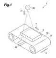
- Fig. 1 is a perspective view of an X-ray foreign substance inspection device according to the present embodiment
- Fig. 2 is a schematic configuration view of the X-ray foreign substance inspection device according to the present embodiment.
- the X-ray foreign substance inspection device 1 irradiates X-rays (radiation) from an X-ray source onto a specimen S in an irradiation direction Z, and detects transmitted X-rays transmitted through the specimen S of the irradiated X-rays in a plurality of energy ranges.
- the X-ray foreign substance inspection device 1 carries out a foreign substance inspection and a baggage inspection, etc., to detect foreign substances included in a specimen S by using a transmitted X-ray image.
- Such an X-ray foreign substance inspection device 1 includes a belt conveyor 10, an X-ray irradiator 20, a low energy image acquisition section 30, a high energy image acquisition section 40, a timing control section 50, a timing calculation section 60, and an image processing device 70.
- the low energy image acquisition section 30, the high energy image acquisition section 40, and the timing control section 50 constitute a dual-energy radiation detection device 80 according to an embodiment of the present invention.
- the belt conveyor 10 includes a belt portion 12 on which a specimen S is placed as shown in Fig. 1 .
- the belt conveyor 10 conveys the specimen S in a conveying direction Y at a predetermined conveying speed by moving the belt portion 12 in the conveying direction Y
- the conveying speed of the specimen S is, for example, 48 m/min.
- the belt conveyor 10 can change the conveying speed to, for example, 24 m/min and 96 m/min by the belt conveyor control section 14 as appropriate.
- the belt conveyor control section 14 can change the height position of the belt portion 12. By changing the height position of the belt portion 12, the distance between the X-ray irradiator 20 and the specimen S can be changed.
- the specimen S to be conveyed by the belt conveyor 10 is composed of various objects, for example, foods such as meat, rubber products such as tires, baggage and cargo to be subjected to baggage inspections and cargo inspections for security and safety, and other resin products and metal products, resource materials such as mineral substances, waste to be separated and collected (recycled) as resources, and electronic components, etc.
- the X-ray irradiator 20 is an X-ray source that irradiates X-rays in the irradiation direction Z onto the specimen S.
- the X-ray irradiator 20 is a point light source, and diffuses and irradiates X-rays in a predetermined angle range in a detection direction X orthogonal to the irradiation direction Z and the conveying direction Y.
- the X-ray irradiator 20 is disposed above the belt portion 12 at a predetermined distance to the belt portion 12 so that the X-ray irradiation direction Z is directed toward the belt portion 12 and X-rays diffuse to the entirety in the width direction (detection direction X) of the specimen S.
- the X-ray irradiator 20 has an irradiation range set to a predetermined divided region in the longitudinal direction (conveying direction Y) of the specimen S, and by conveying the specimen S in the conveying direction Y by the belt conveyor 10, X-rays are irradiated onto the entirety in the longitudinal direction of the specimen S.
- the low energy image acquisition section 30 includes a low energy detector (first radiation detector) 32 and a low energy image correction section (image correction section) 34.
- the low energy detector 32 is positioned on the upstream side with respect to the X-ray incident direction Z, and detects X-rays in a low-energy range (first energy range) transmitted through the specimen S of the X-rays irradiated from the X-ray irradiator 20 and generates low energy image data (first radiation image data).
- the low energy image correction section 34 is a section that amplifies and corrects low energy image data generated by the low energy detector 32.
- the low energy image correction section 34 includes an amplifier 34a that amplifies low energy image data, an A/D converter 34b that converts the low energy image data amplified by the amplifier 34a, a correction circuit 34c that applies predetermined correction processing to the low energy image data converted by the A/D converter 34b, and an output interface 34d that outputs the image data corrected by the correction circuit 34c to the outside.
- the details of the low energy image correction section (image correction section) 34 will be described later.
- the high energy image acquisition section 40 includes a high energy detector (second radiation detector) 42 and a high energy image correction section 44.
- the high energy detector 42 is positioned on the downstream side with respect to the X-ray incident direction Z, and detects X-rays in a high-energy range (second energy range) transmitted through the specimen S and the low energy detector 32 of the X-rays irradiated from the X-ray irradiator 20 and generates high energy image data (second radiation image data).
- the low-energy range detected by the low energy detector 32 and the high-energy range detected by the high energy detector 42 are not clearly discriminated from each other, but overlap to some extent.
- the high energy image correction section 44 is a section that amplifies and corrects high energy image data generated by the high energy detector 42.
- the high energy image correction section 44 includes an amplifier 44a that amplifies high energy image data, an A/D converter 44b that A/D converts the high energy image data amplified by the amplifier 44a, a correction circuit 44c that applies predetermined correction processing to the high energy image data converted by the A/D converter 44b, and an output interface 44d that outputs the image data corrected by the correction circuit 44c to the outside.
- the timing control section 50 controls transmitted X-ray detection timings in the low energy detector 32 and transmitted X-ray detection timings in the high energy detector 42.
- the timing control section 50 reduces an image deviation in the following subtraction processing according to detection timings calculated by the timing calculation section 60 so that low energy image data and high energy image data correspond to each other. The details of the timing control section 50 and the timing calculation section 60 will be described later.
- the image processing device 70 is a device that generates a subtraction image as a synthesized image by carrying out arithmetic processing (subtraction processing) for calculating difference data between low energy image data detected and generated by the low energy detector 32 and high energy image data detected and generated by the high energy detector 42.
- the detection timings of both energy image data to be input into the image processing device 70 are controlled by the timing control section 50 so that both image data correspond to each other.
- the image processing device 70 outputs the subtraction image generated by the arithmetic processing to a display, etc., and displays it thereon. By this output display, foreign substances, etc., included in the specimen S can be visually confirmed. It is also possible that the subtraction image is not output and displayed but only data is output so that foreign substances, etc., included in the specimen S are directly detected from the image data by detection processing on the image data.
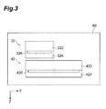
- Fig. 3 is a schematic structural drawing of a dual-energy sensor 86 consisting of the low energy detector 32 and the high energy detector 42 in the radiation detection device 80 shown in Fig. 2
- Fig. 4 is a drawing showing an X-ray incidence plane (a) of the low energy detector 32 and an X-ray incidence plane (b) of the high energy detector 42.
- the low energy detector 32 includes a low energy scintillator layer (first scintillator layer) 322 and a low energy line sensor (first pixel section) 324.
- the low energy scintillator layer 322 extends along the image detection direction X and converts an image of X-rays in the low-energy range into an optical image.
- the low energy line sensor 324 includes a plurality of pixels 326 arrayed along the image detection direction X, and acquires a low energy image (first image) based on the optical image converted by the low energy scintillator layer 322.
- the low energy detector 32 detects X-rays in the low-energy range.
- the high energy detector 42 includes a high energy scintillator layer (second scintillator layer) 422 and a high energy line sensor (second pixel section) 424.
- the high energy scintillator layer 422 extends along the image detection direction X and converts an image of X-rays in the high-energy range into an optical image.
- the high energy line sensor 424 includes a plurality of pixels 426 arrayed along the image detection direction X, and acquires a high energy image (second image) based on the optical image converted by the high energy scintillator layer 422. The high energy detector 42 thus detects X-rays in the high-energy range.
- the pixel width (first image detection direction width) Wa1 in the image detection direction X of each of the plurality of pixels 326 in the low energy line sensor 324 is equal to the pixel width (second image detection direction width) Wa2 in the image detection direction X of each of the plurality of pixels 426 in the high energy line sensor 424.
- the pixel width (first orthogonal direction width) Wb1 in an orthogonal direction (conveying direction Y) orthogonal to the image detection direction X of each of the plurality of pixels 326 in the low energy line sensor 324 is smaller than the pixel width (second orthogonal direction width) Wb2 in the orthogonal direction Y of each of the plurality of pixels 426 in the high energy line sensor 424.
- the area (first area) S1 of each of the plurality of pixels 326 in the low energy line sensor 324 is smaller than the area (second area) S2 of each of the plurality of pixels 426 in the high energy line sensor 424.
- the number of pixels (the number of line outputs) in the low energy line sensor 324 is larger than the number of pixels (the number of line outputs) in the high energy line sensor 424.
- the material of the low energy scintillator layer 322 and the material of the high energy scintillator layer 422 may be the same, or may be different from each other.
- Gd2O2S: Tb, CsI: Tl, CdWO4, CaWO4 GSO, LGSO, BGO, LSO, YSO, YAP, Y2O2S: Tb, YTaO4: Tm, etc. are applicable, and a combination of materials is selected according to X-rays to be detected.
- the low energy detector 32 and the high energy detector 42 may be X-ray detectors having an energy discrimination function using a direct conversion system of CdTe (cadmium telluride), etc.
- a foreign substance inspection in foods it is required to carry out the inspection to detect bone, cartilage, and metal, etc., in meat as a foreign substance, and by utilizing the difference in radiation absorption between meat and a foreign substance (bone, cartilage, and metal, etc.), a foreign substance is made to stand out due to contrast differences in a subtraction image of radiation images transmitted through these, and it is determined whether a foreign substance is present.
- bone and metal differ greatly in radiotransparency from (lower than) that of meat, so that a contrast difference in at least a radiation image acquired with one of the radiation detectors is great.
- a contrast difference in a subtraction image of two radiation images is great, so that a foreign substance inspection is easily carried out.
- cartilage, like meat has high radiotransparency, and the difference in radiotransparency between these is small, so that contrast differences in radiation images acquired with both radiation detectors become small.
- a contrast difference in a subtraction image of these radiation images is also small, so that a foreign substance inspection was difficult.
- the low energy detector 32 that detects a radiation image in the low-energy range, which can make a contrast difference in a radiation image between lightweight atoms of meat and cartilage, etc., that is, between substances both having high radiotransparency comparatively large
- the pixel width Wb1 in the conveying direction Y of each pixel 326 is reduced, that is, the area S1 of each pixel 326 in the low energy detector 32 is made smaller, a charge amount to be converted by each pixel 326 becomes smaller, and a charge amount difference in a radiation image between lightweight atoms of meat and cartilage, etc., that is, between substances both having high radiotransparency, can be made relatively large, and a contrast difference in a radiation image of these can be made larger.
- a foreign substance inspection can be easily carried out.
- Fig. 5 is a conceptual diagram showing image processing (a) by the low energy image correction section 34 and image processing (b) by the high energy image correction section 44.
- the number of pixels of an image to be output from the low energy detector 32 becomes M x N as a result of two-dimensional image processing applied to M pixels (detection direction X) x N line outputs (conveying direction Y).
- the number of pixels of an image to be output from the high energy detector 42 becomes M x N' (N' ⁇ N) as a result of two-dimensional image processing applied to M pixels (detection direction X) x N' line outputs (conveying direction Y).
- the number of line outputs N of the image to be output from the low energy detector 32 and the number of line outputs N' of the image to be output from the high energy detector 42 are different from each other, that is, the number of pixels N in the conveying direction Y of the image from the low energy detector 32 and the number of pixels N' in the conveying direction Y of the image from the high energy detector 42 are different from each other, and therefore, it is difficult to create a subtraction image by carrying out different processing of these images.
- the timing control section 50 makes the number of line outputs N of the image to be output from the low energy detector 32 and the number of line outputs N' of the image to be output from the high energy detector 42 equal to each other by synchronizing the detection timings of the low energy detector 32 and the detection timings of the high energy detector 42 with each other. Specifically, the number of pixels N in the conveying direction Y of the image from the low energy detector 32 and the number of pixels N' in the conveying direction Y of the image from the high energy detector 42 are made equal to each other.
- Fig. 6 is a conceptual diagram of detection timing control to be carried out by the timing control section 50
- Fig. 7 is a drawing showing pixel data (a) of the image to be output from the low energy detector 32 and pixel data (b) of the image to be output from the high energy detector 42.
- the timing control section 50 supplies repetitive pulse signals for detection timings to the low energy detector 32 and the high energy detector 42.
- the timing control section 50 synchronizes the detection timings with each other by synchronizing these repetitive pulse signals with each other.
- the repetitive pulse signals are controlled according to control signals from the timing calculation section 60 by using, for example, PLL (Phase Locked Loop: phase synchronization circuit), etc.
- the values of the control signals are adjusted by considering, for example, the conveying speed V of the belt conveyor 10, the pixel width Wb1 or Wb2 in the conveying direction Y of the pixels of the line sensor, the distance FOD from the light source 20 to the specimen S, and the distance FDD from the light source 20 to the detector 32 or 42, etc.
- Respective values are set by, for example, a user in advance.
- the timing control section 50 controls the period of the repetitive pulse signal for the low energy detector 32 to the pixel width Wb1 in the conveying direction Y of the pixel 326 in the low energy detector 32, and synchronizes the period of the repetitive pulse signal for the high energy detector 42 with the period of the repetitive pulse signal for the low energy detector 32.
- the detection timings of the high energy detector 42 that has the larger pixel width in the conveying direction Y are adjusted not by the pixel width Wb2 of its own pixel 426 but by the pixel width Wb1 of the pixel 326 in the low energy detector 32.
- pixel data A is detected by the low energy detector 32, and pixel data A + noise N can be detected by the high energy detector 42.
- pixel data B is detected by the low energy detector 32, and pixel data B + A can be detected by the high energy detector 42.
- pixel data C is detected by the low energy detector 32, and pixel data C + B can be detected by the high energy detector 42.
- pixel data D is detected by the low energy detector 32, and pixel data D + C can be detected by the high energy detector 42.
- pixel data E is detected by the low energy detector 32, and pixel data E + D can be detected by the high energy detector 42.
- pixel data F is detected by the low energy detector 32, and pixel data F + E can be detected by the high energy detector 42.
- pixel data G is detected by the low energy detector 32, and pixel data G + F can be detected by the high energy detector 42.
- noise N is detected by the low energy detector 32, and noise N + pixel data G can be detected by the high energy detector 42.
- correction processing is carried out to match pixel data of the low energy detector 32 side and pixel data of the high energy detector 42 side by the correction circuit 34c in the low energy image correction section 34.
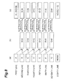
- the correction circuit 34c in the low energy image correction section 34 sums Wb2/Wb1 pixel data successive in the image from the low energy detector 32 based on the ratio Wb2/Wb1 of the pixel width Wb2 of each pixel 426 in the high energy detector 42 to the pixel width Wb1 of each pixel 326 in the low energy detector 32.
- Wb2/Wb1 2 and therefore, as shown in Fig. 8 , the correction circuit 34c generates correction data B+A by adding, to the pixel data B detected at the second line, pixel data A detected one line before, generates correction data C+B by adding, to the pixel data C detected at the third line, the pixel data B detected one line before, generates correction data D+C by adding, to pixel data D detected at the fourth line, the pixel data C detected one line before, generates correction data E+D by adding, to pixel data E detected at the fifth line, the pixel data D detected one line before, generates correction data F+E by adding, to pixel data F detected at the sixth line, the pixel data E detected one line before, and generates correction data G+F by adding, to pixel data G detected at the seventh line, the pixel data F detected one line before.
- the correction circuit 34c generates correction data B+A, C+B, D+C, E+D, F+E, and G+F corresponding to pixel data B+A, C+B, D+C, E+D, F+E, and G+F of the high energy detector 42 side, respectively.
- the detection timings of the high energy detector 42 are synchronized to the detection timings of the low energy detector 32 by the timing control section 50, so that the high energy detector 42 acquires pixel data multiplied by the ratio Wb2/Wb1 of the pixel width Wb2 to the pixel width Wb1 in the conveying direction Y with respect to the low energy detector 32.
- the correction circuit 34c in the low energy image correction section 34 based on the ratio Wb2/Wb1 of the pixel width Web2 to the pixel width Wb1, Wb2/Wb1 pixel data successive in the image from the low energy detector 32 are summed, so that the corrected number of pixels in the image from the low energy detector 32 and the number of pixels in the image from the high energy detector 42 can be made equal to each other.
- arithmetic processing for example, subtraction processing based on a radiation image acquired with the low energy detector 32 and a radiation image acquired with the high energy detector 42 can be easily carried out.
- Fig. 9 is a view showing an image (a) detected by the low energy detector 32 and an image (b) detected by the high energy detector 42 when the detection timing control and the image correction processing according to the present embodiment are not carried out
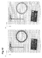
- Fig. 10 is a view showing an image (a) detected by the low energy detector 32 and an image (b) detected by the high energy detector 42 when the detection timing control and the image correction processing according to the present embodiment are carried out
- Fig. 11 shows a subtraction image based on the images shown in Fig. 10 .
- the number of pixels in the conveying direction Y of the image from the low energy detector 32 and the number of pixels in the conveying direction Y of the image from the high energy detector 42 are different from each other, so that it is difficult to generate a subtraction image based on these images.
- the present embodiment shows an example in which the timing control section 50, the low energy image correction section 34, and the high energy image correction section 44 are configured by hardware, however, the timing control section 50, the low energy image correction section 34, and the high energy image correction section 44 may be realized by, for example, software processing on an external computer. Specifically, it is possible that the timing control section and the image correction section according to the present invention are realized by computer programs, and the detection timing control processing and the pixel correction processing according to the present invention are carried out by software.
- the low energy detector 32 and the high energy detector 42 are arranged so that their left ends match each other is illustrated, however, various arrangements of the low energy detector 32 and the high energy detector 42 are possible.
- the low energy detector 32 and the high energy detector 42 may be arranged so that their central axes match each other.
- the low energy detector 32 and the high energy detector 42 are possible, however, depending on the arrangement, it is preferable that either the detection timings of the low energy detector 32 or the detection timings of the high energy detector 42 are delayed.
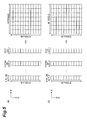
- Fig. 12 is a diagram showing brightness files of images when detecting the same specimen.
- the specimen has a high-transmittance portion with a length corresponding to three pixels, and in Fig. 12(a) , detection timings are adjusted so that the high-transmittance portion of the specimen can be detected at the detection timings 4 to 7.
- Fig. 12(b) shows a brightness file when the detection timings are different by a 1/2 pixel from the detection timings in Fig. 12(a)
- Fig. 12(c) shows a brightness file when the detection timings are different by a 1/4 pixel from the detection timings in Fig. 12(a) .
- Fig. 13 is a diagram showing brightness files of subtraction images based on images with the brightness files shown in Fig. 12 .
- Fig. 13(a) shows a brightness file of a subtraction image based on an image with the brightness file shown in Fig. 12(a) and an image with the brightness file shown in Fig. 12(b) , that is, a brightness file of a subtraction image based on images the detection timings of which are different by a 1/2 pixel from each other.
- positive pseudo edges are generated before and after the high-transmittance portion of the specimen. This generation of positive pseudo edges becomes a cause of generation of white edges described later in a subtraction image.
- Fig. 13(a) shows a brightness file of a subtraction image based on an image with the brightness file shown in Fig. 12(a) and an image with the brightness file shown in Fig. 12(b) , that is, a brightness file of a subtraction image based on images the detection timings of which are different by a 1/2
- FIG. 13(b) shows a brightness file of a subtraction image based on an image with the brightness file shown in Fig. 12(a) and an image with the brightness file shown in Fig. 12(c) , that is, a brightness file of a subtraction image based on images the detection timings of which are different by a 1/4 pixel from each other.
- a positive pseudo edge is generated before the high-transmittance portion of the specimen, and a negative pseudo edge is generated after the high-transmittance portion of the specimen.
- Generation of the positive pseudo edge becomes a cause of generation of a white edge described later in a subtraction image
- generation of a negative pseudo edge becomes a cause of generation of a black edge described later in a subtraction image.
- Fig. 14 is a view showing an example of a subtraction image based on two images the detection timings of which are different from each other. Referring to Fig. 14 , white edges are generated at portions on the lower sides of the substances in the specimen, and black edges are generated at portions on the upper sides. Thus, if the detection timings in two detectors for a detecting portion on a specimen differ greatly, an excellent subtraction image may not be obtained.
- either the detection timings of the low energy detector 32 or the detection timings of the high energy detector 42 are preferably delayed so as to reduce the position deviations between the detection positions on the specimen at the detection timings of one detector and the detection positions on the specimen at the detection timings of the other detector.
- a delay time is applied to the detection timings of either one detector so that the low energy detector 32 detects only pixel data C not including adjacent pixel data B and D when detecting the third line, and the high energy detector 42 detects only pixel data B+C not including adjacent pixel data A and D when detecting the third line.
- the delay time of either the detection timings of the low energy detector 32 or the detection timings of the high energy detector 42 must be adjusted so as to reduce the position deviations between the detection positions on the specimen at the detection timings of one detector and the detection positions on the specimen at the detection timings of the other detector.
- the pixel width Wb1 of each pixel 326 is made smaller than the pixel width Wb2 of each pixel 426, however, it is also possible that, as shown in Fig. 15 , the pixel width Wa1 of each pixel 326 may be made smaller than the pixel width Wa2 of each pixel 426.
- image thinning-out processing may be carried out in one radiation detector and image interpolation processing may be carried out in the other radiation detector.
- the present invention is applicable to uses that make easy arithmetic processing based on radiation images acquired with two radiation detectors even when the numbers of pixels of the radiation detectors are different from each other.
Landscapes
- Physics & Mathematics (AREA)
- Life Sciences & Earth Sciences (AREA)
- General Physics & Mathematics (AREA)
- General Health & Medical Sciences (AREA)
- Health & Medical Sciences (AREA)
- Immunology (AREA)
- Biochemistry (AREA)
- Analytical Chemistry (AREA)
- Chemical & Material Sciences (AREA)
- Pathology (AREA)
- High Energy & Nuclear Physics (AREA)
- General Life Sciences & Earth Sciences (AREA)
- Geophysics (AREA)
- Analysing Materials By The Use Of Radiation (AREA)
- Apparatus For Radiation Diagnosis (AREA)
- Measurement Of Radiation (AREA)
- Nuclear Medicine, Radiotherapy & Molecular Imaging (AREA)
- Radiology & Medical Imaging (AREA)
Abstract
Description
- The present invention relates to a dual-energy radiation detection device.
- Radiation detection devices that detect foreign substances, measure a component distribution, and measure weights, etc., in an in-line non-destructive inspection of a specimen that is conveyed by a belt conveyor or the like have been known. A radiation detection device includes a radiation detector having a scintillator layer and pixels, and detects radiation transmitted through a specimen and generates a radiation image.
- This kind of radiation detection device is disclosed in
Patent Literature 1. The radiation detection device described inPatent Literature 1 includes two radiation detectors with different pixel areas arranged side by side in a conveying direction of a belt conveyor. In this radiation detection device, large foreign substances are detected by the radiation detector with a larger pixel area, and small foreign substances are detected by the radiation detector with a smaller pixel area. By thus selecting a pixel size in advance according to a size of a foreign substance that a user desires to detect, foreign substance inspection accuracy can be improved. - As another method for improving the foreign substance inspection accuracy, a dual-energy radiation detection device has been known. A dual-energy radiation detection device includes two radiation detectors with different energy sensitivities, and detects radiation in a low-energy range (first energy range) and radiation in a high-energy range (second energy range) transmitted through a specimen. With this radiation detection device, a radiation image in a low-energy range and a radiation image in a high-energy range are simultaneously acquired, an image to which weighted subtraction and superimposition (for example, subtraction) is applied is created based on the radiation images, and according to a contrast difference in this image, a foreign substance is made to stand out, whereby realizing a foreign substance inspection with high accuracy.
-
- [Patent Literature 1] Japanese Patent Application Laid-Open No.
2009-85627 - For example, in an inspection of foreign substances in foods, it is required to carry out an inspection to detect bone, cartilage, and metal, etc., in meat as a foreign substance, and by utilizing the difference in radiation absorption between meat and a foreign substance (bone, cartilage, and metal, etc.), based on a contrast difference in a subtraction image of radiation images transmitted through these, a foreign substance is made to stand out, and accordingly, it is determined whether a foreign substance is present.
- Here, bone and metal differ greatly in radiotransparency from (lower than) that of meat, so that a contrast difference in at least a radiation image acquired with one of the radiation detectors is great. As a result, a contrast difference in a subtraction image of the two radiation images is great, so that a foreign substance inspection can be easily carried out. However, cartilage, like meat, has high radiotransparency, and a difference in radiotransparency between these is small, so that the contrast differences in radiation images acquired with the radiation detectors become small. As a result, a contrast difference in a subtraction image of these radiation images also becomes small, so that the foreign substance inspection was difficult.
- In this regard, as a result of intensive study, the inventors of the present invention found that a contrast difference in a radiation image between lightweight atoms of meat and cartilage, etc., that is, between substances both having high radiotransparency could be made larger in a radiation image in a lower energy range. Further, the inventors of the present invention found that, when a charge amount to be converted by each pixel was reduced by reducing the areas of pixels in the radiation detector for low-energy range detection, a charge amount difference in a radiation image between substances both having high radiotransparency could be made relatively large, and a contrast difference in a radiation image of these could be increased.
- However, to reduce the areas of the pixels in the low energy radiation detector, if the pixel width in the direction orthogonal to the pixel array direction (image detection direction) is made smaller and the number of pixels (the number of line outputs) increases, the number of pixels (the number of line outputs) to be output from the low energy radiation detector and the number of pixels (the number of line outputs) to be output from the high energy radiation detector become different from each other, and as a result, it becomes difficult to carry out subtraction processing, that is, difference processing.
- Therefore, an object of the present invention is to provide a radiation detection device that can easily carry out arithmetic processing based on radiation images acquired with two radiation detectors even when the radiation detectors have a different number of pixels.
- A radiation detection device according to the present invention is a radiation detection device for a foreign substance inspection using a subtraction method, which detects radiation in a first energy range and radiation in a second energy range higher than the radiation in the first energy range that are transmitted through a specimen and incident from a radiation incident direction, comprising: a first radiation detector that is positioned on the upstream side with respect to the radiation incident direction, and detects radiation in the first energy range and generates an image corresponding to an image of the radiation; a second radiation detector that is positioned on the downstream side with respect to the radiation incident direction, and detects radiation in the second energy range and generates an image corresponding to an image of the radiation; a timing control section that controls detection timings of the first radiation detector and detection timings of the second radiation detector; and an image correction section that corrects an image from the first radiation detector. The first radiation detector includes a first pixel section that has a plurality of pixels arrayed along an image detection direction and acquires a first image based on an image of radiation in the first energy range, and the second radiation detector includes a second pixel section that has a plurality of pixels arrayed along the image detection direction and acquires a second image based on an image of radiation in the second energy range. A first pixel width Wb1in an orthogonal direction orthogonal to the image detection direction of each of the plurality of pixels in the first pixel section is smaller than a second pixel width Wb2 in the orthogonal direction of each of the plurality of pixels in the second pixel section, the timing control section synchronizes detection timings of the second radiation detector to detection timings of the first radiation detector, and the image correction section sums Wb2/Wb1 pixel data successive in the image from the first radiation detector based on a ratio Wb2/Wb1 of the second pixel width Wb2 to the first pixel width Wb1.
- When using a subtraction method, the two radiation detectors are required to image spatially and temporally the same position on a specimen. Therefore, with the type including two radiation detectors arranged side by side as described in
Patent Literature 1, the detection timings of the radiation detectors must be adjusted. Even after the detection timings are adjusted, it is still difficult for the radiation detectors to image the same position, that is, exactly the same area in a specimen, so that position accuracy may become low. Thus, if a subtraction image in which the ends of the detection areas partially deviate from each other is created, pseudo edges such as a bright edge (white edge) and a dark edge (black edge) may be formed at an end portion of the detected object in the subtraction image. - On the other hand, in this radiation detection device, the first radiation detector and the second radiation detector are disposed so as to overlap in the radiation incident direction, that is, the radiation detection device is a vertically-piled type, so that the radiation detectors can easily image temporally the same position on a specimen without detection timing control simultaneously.
- With this radiation detection device, detection timings of the second radiation detector are synchronized to detection timings of the first radiation detector by the timing control section so that at one detection timing, the second radiation detector acquires pixel data multiplied by the ratio Wb2/Wb1 of the second pixel width Wb2 to the first pixel width Wb1. Then, by the image correction section, based on the ratio Wb2/Wb1 of the second pixel width Wb2 to the first pixel width Wb1, Wb2/Wb1 pixel data successive in the image from the first radiation detector are summed, so that the corrected number of pixels of the image from the first radiation detector can be made equal to the number of pixels of the image from the second radiation detector. Therefore, even when the first pixel width in the orthogonal direction orthogonal to the image detection direction of the pixel in the first radiation detector is smaller than the second pixel width in the orthogonal direction of the pixel in the second radiation detector, that is, the number of pixels in the first radiation detector and the number of pixels in the second radiation detector are different from each other, arithmetic processing, for example, subtraction processing based on a radiation image acquired with the first radiation detector and a radiation image acquired with the second radiation detector can be easily carried out.
- The above-described first radiation detector and the above-described second radiation detector are preferably arranged so that position deviations between detection positions on a specimen at detection timings of the first radiation detector and detection positions on the specimen at detection timings of the second radiation detector are not more than 0.3 times the first pixel width.
- Due to an arrangement of the first radiation detector and the second radiation detector, a detection position on a specimen at a detection timing of the first radiation detector and a detection position on the specimen at a detection timing of the second radiation detector may greatly deviate from each other. Then, in a subtraction image based on a radiation image acquired with the first radiation detector and a radiation image acquired with the second radiation detector, a white edge and a black edge may appear before and after a portion corresponding to this detection position.
- However, when the first radiation detector and the second radiation detector are arranged so that the position deviations between the detection positions on the specimen at the detection timings of the first radiation detector and the detection positions on the specimen at the detection timings of the second radiation detector become not more than 0.3 times the first pixel width, in a subtraction image based on a radiation image acquired with the first radiation detector and a radiation image acquired with the second radiation detector, a white edge and a black edge can be prevented from appearing before and after a portion corresponding to this detection position, and an excellent subtraction image can be obtained.
- The above-described timing control section preferably delays either the detection timings of the first radiation detector or the detection timings of the second radiation detector.
- Accordingly, a position deviation between a detection position on the specimen at a detection timing of the first radiation detector and a detection position on the specimen at a detection timing of the second radiation detector due to an arrangement of the first radiation detector and the second radiation detector can be reduced. Therefore, a white edge and a black edge can be prevented from appearing before and after a portion corresponding to this detection position in a subtraction image based on a radiation image acquired with the first radiation detector and a radiation image acquired with the second radiation detector, so that an excellent subtraction image can be obtained.
- The first radiation detector described above includes a first scintillator layer that extends along the image detection direction and converts an image of radiation in the first energy range into an optical image, and a first pixel section that acquires a first image based on the optical image converted by the first scintillator layer, and the second radiation detector described above includes a second scintillator layer that extends along the image detection direction and converts an image of radiation in the second energy range into an optical image, and a second pixel section that acquires a second image based on the optical image converted by the second scintillator layer.
- According to the present invention, in a dual-energy radiation detection device using a subtraction method, even when the number of pixels of two radiation detectors are different from each other, arithmetic processing, for example, subtraction processing based on radiation images acquired with these radiation detectors can be easily carried out.
-
-
Fig. 1 is a perspective view of an X-ray foreign substance inspection device according to the present embodiment. -
Fig. 2 is a schematic configuration view of the X-ray foreign substance inspection device according to the present embodiment. -
Fig. 3 is a schematic structural drawing of a dual-energy sensor in a radiation detection device according to an embodiment of the present invention. -
Fig. 4 is a drawing showing X-ray incidence planes of a low energy detector and a high energy detector in the dual-energy sensor shown inFig. 3 . -
Fig. 5 is a conceptual diagram showing image processings in a low energy image correction section and a high energy image correction section shown inFig. 2 . -
Fig. 6 is a conceptual diagram of detection timing control to be carried out by the timing control section shown inFig. 2 . -
Fig. 7 is a drawing showing pixel data of images output from the low energy detector and the high energy detector shown inFig. 2 . -
Fig. 8 is a conceptual diagram showing image correction processing to be carried out by the low energy image correction section shown inFig. 2 . -
Fig. 9 is a view showing images detected by the low energy detector and the high energy detector when detection timing control and image correction processing according to the present embodiment are not carried out. -
Fig. 10 is a view showing images detected by the low energy detector and the high energy detector when detection timing control and image correction processing according to the present embodiment are carried out. -
Fig. 11 shows a subtraction image based on the images shown inFig. 10 . -
Fig. 12 is a diagram showing brightness files of images when detecting the same specimen. -
Fig. 13 is a diagram showing brightness files of subtraction images based on images with the brightness files shown inFig. 12 . -
Fig. 14 is a diagram showing an example of a subtraction image based on two images the detection timings of which are different from each other. -
Fig. 15 is a drawing showing X-ray incidence planes of a low energy detector and a high energy detector in a dual-energy sensor according to an exemplary variation of the present invention. - Hereinafter, a preferred embodiment of the present invention is described with reference to the drawings. In the drawings, portions identical to or equivalent to each other are designated by the same reference signs.
-
Fig. 1 is a perspective view of an X-ray foreign substance inspection device according to the present embodiment, andFig. 2 is a schematic configuration view of the X-ray foreign substance inspection device according to the present embodiment. As shown inFig. 1 andFig. 2 , the X-ray foreignsubstance inspection device 1 irradiates X-rays (radiation) from an X-ray source onto a specimen S in an irradiation direction Z, and detects transmitted X-rays transmitted through the specimen S of the irradiated X-rays in a plurality of energy ranges. The X-ray foreignsubstance inspection device 1 carries out a foreign substance inspection and a baggage inspection, etc., to detect foreign substances included in a specimen S by using a transmitted X-ray image. Such an X-ray foreignsubstance inspection device 1 includes abelt conveyor 10, anX-ray irradiator 20, a low energyimage acquisition section 30, a high energyimage acquisition section 40, atiming control section 50, atiming calculation section 60, and animage processing device 70. The low energyimage acquisition section 30, the high energyimage acquisition section 40, and thetiming control section 50 constitute a dual-energyradiation detection device 80 according to an embodiment of the present invention. - The
belt conveyor 10 includes abelt portion 12 on which a specimen S is placed as shown inFig. 1 . Thebelt conveyor 10 conveys the specimen S in a conveying direction Y at a predetermined conveying speed by moving thebelt portion 12 in the conveying direction Y The conveying speed of the specimen S is, for example, 48 m/min. Thebelt conveyor 10 can change the conveying speed to, for example, 24 m/min and 96 m/min by the beltconveyor control section 14 as appropriate. The beltconveyor control section 14 can change the height position of thebelt portion 12. By changing the height position of thebelt portion 12, the distance between theX-ray irradiator 20 and the specimen S can be changed. By this change, the resolution of X-ray transmitted images to be acquired with the low energyimage acquisition section 30 and the high energyimage acquisition section 40 can be changed. The specimen S to be conveyed by thebelt conveyor 10 is composed of various objects, for example, foods such as meat, rubber products such as tires, baggage and cargo to be subjected to baggage inspections and cargo inspections for security and safety, and other resin products and metal products, resource materials such as mineral substances, waste to be separated and collected (recycled) as resources, and electronic components, etc. - The
X-ray irradiator 20 is an X-ray source that irradiates X-rays in the irradiation direction Z onto the specimen S. TheX-ray irradiator 20 is a point light source, and diffuses and irradiates X-rays in a predetermined angle range in a detection direction X orthogonal to the irradiation direction Z and the conveying direction Y. TheX-ray irradiator 20 is disposed above thebelt portion 12 at a predetermined distance to thebelt portion 12 so that the X-ray irradiation direction Z is directed toward thebelt portion 12 and X-rays diffuse to the entirety in the width direction (detection direction X) of the specimen S. TheX-ray irradiator 20 has an irradiation range set to a predetermined divided region in the longitudinal direction (conveying direction Y) of the specimen S, and by conveying the specimen S in the conveying direction Y by thebelt conveyor 10, X-rays are irradiated onto the entirety in the longitudinal direction of the specimen S. - The low energy
image acquisition section 30 includes a low energy detector (first radiation detector) 32 and a low energy image correction section (image correction section) 34. - The
low energy detector 32 is positioned on the upstream side with respect to the X-ray incident direction Z, and detects X-rays in a low-energy range (first energy range) transmitted through the specimen S of the X-rays irradiated from theX-ray irradiator 20 and generates low energy image data (first radiation image data). - The low energy
image correction section 34 is a section that amplifies and corrects low energy image data generated by thelow energy detector 32. The low energyimage correction section 34 includes anamplifier 34a that amplifies low energy image data, an A/D converter 34b that converts the low energy image data amplified by theamplifier 34a, acorrection circuit 34c that applies predetermined correction processing to the low energy image data converted by the A/D converter 34b, and anoutput interface 34d that outputs the image data corrected by thecorrection circuit 34c to the outside. The details of the low energy image correction section (image correction section) 34 will be described later. - The high energy
image acquisition section 40 includes a high energy detector (second radiation detector) 42 and a high energyimage correction section 44. - The
high energy detector 42 is positioned on the downstream side with respect to the X-ray incident direction Z, and detects X-rays in a high-energy range (second energy range) transmitted through the specimen S and thelow energy detector 32 of the X-rays irradiated from theX-ray irradiator 20 and generates high energy image data (second radiation image data). The low-energy range detected by thelow energy detector 32 and the high-energy range detected by thehigh energy detector 42 are not clearly discriminated from each other, but overlap to some extent. - The high energy
image correction section 44 is a section that amplifies and corrects high energy image data generated by thehigh energy detector 42. The high energyimage correction section 44 includes anamplifier 44a that amplifies high energy image data, an A/D converter 44b that A/D converts the high energy image data amplified by theamplifier 44a, acorrection circuit 44c that applies predetermined correction processing to the high energy image data converted by the A/D converter 44b, and anoutput interface 44d that outputs the image data corrected by thecorrection circuit 44c to the outside. - The
timing control section 50 controls transmitted X-ray detection timings in thelow energy detector 32 and transmitted X-ray detection timings in thehigh energy detector 42. Thetiming control section 50 reduces an image deviation in the following subtraction processing according to detection timings calculated by thetiming calculation section 60 so that low energy image data and high energy image data correspond to each other. The details of thetiming control section 50 and thetiming calculation section 60 will be described later. - The
image processing device 70 is a device that generates a subtraction image as a synthesized image by carrying out arithmetic processing (subtraction processing) for calculating difference data between low energy image data detected and generated by thelow energy detector 32 and high energy image data detected and generated by thehigh energy detector 42. The detection timings of both energy image data to be input into theimage processing device 70 are controlled by thetiming control section 50 so that both image data correspond to each other. Theimage processing device 70 outputs the subtraction image generated by the arithmetic processing to a display, etc., and displays it thereon. By this output display, foreign substances, etc., included in the specimen S can be visually confirmed. It is also possible that the subtraction image is not output and displayed but only data is output so that foreign substances, etc., included in the specimen S are directly detected from the image data by detection processing on the image data. - Next, the
low energy detector 32 and thehigh energy detector 42 are described in detail.Fig. 3 is a schematic structural drawing of a dual-energy sensor 86 consisting of thelow energy detector 32 and thehigh energy detector 42 in theradiation detection device 80 shown inFig. 2 , andFig. 4 is a drawing showing an X-ray incidence plane (a) of thelow energy detector 32 and an X-ray incidence plane (b) of thehigh energy detector 42. - As shown in
Fig. 3 andFig. 4 , thelow energy detector 32 includes a low energy scintillator layer (first scintillator layer) 322 and a low energy line sensor (first pixel section) 324. The lowenergy scintillator layer 322 extends along the image detection direction X and converts an image of X-rays in the low-energy range into an optical image. The lowenergy line sensor 324 includes a plurality ofpixels 326 arrayed along the image detection direction X, and acquires a low energy image (first image) based on the optical image converted by the lowenergy scintillator layer 322. Thus, thelow energy detector 32 detects X-rays in the low-energy range. - Similarly, the
high energy detector 42 includes a high energy scintillator layer (second scintillator layer) 422 and a high energy line sensor (second pixel section) 424. The highenergy scintillator layer 422 extends along the image detection direction X and converts an image of X-rays in the high-energy range into an optical image. The highenergy line sensor 424 includes a plurality ofpixels 426 arrayed along the image detection direction X, and acquires a high energy image (second image) based on the optical image converted by the highenergy scintillator layer 422. Thehigh energy detector 42 thus detects X-rays in the high-energy range. - Here, the pixel width (first image detection direction width) Wa1 in the image detection direction X of each of the plurality of
pixels 326 in the lowenergy line sensor 324 is equal to the pixel width (second image detection direction width) Wa2 in the image detection direction X of each of the plurality ofpixels 426 in the highenergy line sensor 424. On the other hand, the pixel width (first orthogonal direction width) Wb1 in an orthogonal direction (conveying direction Y) orthogonal to the image detection direction X of each of the plurality ofpixels 326 in the lowenergy line sensor 324 is smaller than the pixel width (second orthogonal direction width) Wb2 in the orthogonal direction Y of each of the plurality ofpixels 426 in the highenergy line sensor 424. Thus, the area (first area) S1 of each of the plurality ofpixels 326 in the lowenergy line sensor 324 is smaller than the area (second area) S2 of each of the plurality ofpixels 426 in the highenergy line sensor 424. Specifically, the number of pixels (the number of line outputs) in the lowenergy line sensor 324 is larger than the number of pixels (the number of line outputs) in the highenergy line sensor 424. - The material of the low
energy scintillator layer 322 and the material of the highenergy scintillator layer 422 may be the same, or may be different from each other. For example, as materials of the lowenergy scintillator layer 322 and the highenergy scintillator layer 422, Gd2O2S: Tb, CsI: Tl, CdWO4, CaWO4 GSO, LGSO, BGO, LSO, YSO, YAP, Y2O2S: Tb, YTaO4: Tm, etc., are applicable, and a combination of materials is selected according to X-rays to be detected. Thelow energy detector 32 and thehigh energy detector 42 may be X-ray detectors having an energy discrimination function using a direct conversion system of CdTe (cadmium telluride), etc. - Here, in a foreign substance inspection in foods, it is required to carry out the inspection to detect bone, cartilage, and metal, etc., in meat as a foreign substance, and by utilizing the difference in radiation absorption between meat and a foreign substance (bone, cartilage, and metal, etc.), a foreign substance is made to stand out due to contrast differences in a subtraction image of radiation images transmitted through these, and it is determined whether a foreign substance is present.
- Here, bone and metal differ greatly in radiotransparency from (lower than) that of meat, so that a contrast difference in at least a radiation image acquired with one of the radiation detectors is great. As a result, a contrast difference in a subtraction image of two radiation images is great, so that a foreign substance inspection is easily carried out. However, cartilage, like meat, has high radiotransparency, and the difference in radiotransparency between these is small, so that contrast differences in radiation images acquired with both radiation detectors become small. As a result, a contrast difference in a subtraction image of these radiation images is also small, so that a foreign substance inspection was difficult.
- However, in the
low energy detector 32 that detects a radiation image in the low-energy range, which can make a contrast difference in a radiation image between lightweight atoms of meat and cartilage, etc., that is, between substances both having high radiotransparency comparatively large, when the pixel width Wb1 in the conveying direction Y of eachpixel 326 is reduced, that is, the area S1 of eachpixel 326 in thelow energy detector 32 is made smaller, a charge amount to be converted by eachpixel 326 becomes smaller, and a charge amount difference in a radiation image between lightweight atoms of meat and cartilage, etc., that is, between substances both having high radiotransparency, can be made relatively large, and a contrast difference in a radiation image of these can be made larger. As a result, a foreign substance inspection can be easily carried out. - Next, the
correction circuit 34c in the low energyimage correction section 34, thetiming control section 50 and thetiming calculation section 60 are described in detail. -
Fig. 5 is a conceptual diagram showing image processing (a) by the low energyimage correction section 34 and image processing (b) by the high energyimage correction section 44. - As shown in
Fig. 5(a) , the number of pixels of an image to be output from thelow energy detector 32 becomes M x N as a result of two-dimensional image processing applied to M pixels (detection direction X) x N line outputs (conveying direction Y). On the other hand, referring toFig. 5(b) , the number of pixels of an image to be output from thehigh energy detector 42 becomes M x N' (N' < N) as a result of two-dimensional image processing applied to M pixels (detection direction X) x N' line outputs (conveying direction Y). - Thus, when the pixel area S1 of the
low energy detector 32 and the pixel area S2 of thehigh energy detector 42 are different from each other, that is, when the pixel width Wb1 in the conveying direction Y of thelow energy detector 32 and the pixel width Wb2 in the conveying direction Y of thehigh energy detector 42 are different from each other, the number of line outputs N of the image to be output from thelow energy detector 32 and the number of line outputs N' of the image to be output from thehigh energy detector 42 are different from each other, that is, the number of pixels N in the conveying direction Y of the image from thelow energy detector 32 and the number of pixels N' in the conveying direction Y of the image from thehigh energy detector 42 are different from each other, and therefore, it is difficult to create a subtraction image by carrying out different processing of these images. - Therefore, the
timing control section 50 makes the number of line outputs N of the image to be output from thelow energy detector 32 and the number of line outputs N' of the image to be output from thehigh energy detector 42 equal to each other by synchronizing the detection timings of thelow energy detector 32 and the detection timings of thehigh energy detector 42 with each other. Specifically, the number of pixels N in the conveying direction Y of the image from thelow energy detector 32 and the number of pixels N' in the conveying direction Y of the image from thehigh energy detector 42 are made equal to each other. -
Fig. 6 is a conceptual diagram of detection timing control to be carried out by thetiming control section 50, andFig. 7 is a drawing showing pixel data (a) of the image to be output from thelow energy detector 32 and pixel data (b) of the image to be output from thehigh energy detector 42. - For example, the
timing control section 50 supplies repetitive pulse signals for detection timings to thelow energy detector 32 and thehigh energy detector 42. Thetiming control section 50 synchronizes the detection timings with each other by synchronizing these repetitive pulse signals with each other. The repetitive pulse signals are controlled according to control signals from thetiming calculation section 60 by using, for example, PLL (Phase Locked Loop: phase synchronization circuit), etc. In thetiming calculation section 60, the values of the control signals, that is, the detection timings are adjusted by considering, for example, the conveying speed V of thebelt conveyor 10, the pixel width Wb1 or Wb2 in the conveying direction Y of the pixels of the line sensor, the distance FOD from thelight source 20 to the specimen S, and the distance FDD from thelight source 20 to thedetector - In detail, the
timing control section 50 controls the period of the repetitive pulse signal for thelow energy detector 32 to the pixel width Wb1 in the conveying direction Y of thepixel 326 in thelow energy detector 32, and synchronizes the period of the repetitive pulse signal for thehigh energy detector 42 with the period of the repetitive pulse signal for thelow energy detector 32. Thus, in the present embodiment, the detection timings of thehigh energy detector 42 that has the larger pixel width in the conveying direction Y are adjusted not by the pixel width Wb2 of itsown pixel 426 but by the pixel width Wb1 of thepixel 326 in thelow energy detector 32. - Then, for example, as shown in
Fig. 6 andFig. 7 , at a first line detection timing, pixel data A is detected by thelow energy detector 32, and pixel data A + noise N can be detected by thehigh energy detector 42. Next, at a second line detection timing, pixel data B is detected by thelow energy detector 32, and pixel data B + A can be detected by thehigh energy detector 42. Next, at a third line detection timing, pixel data C is detected by thelow energy detector 32, and pixel data C + B can be detected by thehigh energy detector 42. Next, at a fourth line detection timing, pixel data D is detected by thelow energy detector 32, and pixel data D + C can be detected by thehigh energy detector 42. Next, at a fifth line detection timing, pixel data E is detected by thelow energy detector 32, and pixel data E + D can be detected by thehigh energy detector 42. Next, at a sixth line detection timing, pixel data F is detected by thelow energy detector 32, and pixel data F + E can be detected by thehigh energy detector 42. Next, at a seventh line detection timing, pixel data G is detected by thelow energy detector 32, and pixel data G + F can be detected by thehigh energy detector 42. Next, at an eighth line detection timing, noise N is detected by thelow energy detector 32, and noise N + pixel data G can be detected by thehigh energy detector 42. - Then, for difference processing, correction processing is carried out to match pixel data of the
low energy detector 32 side and pixel data of thehigh energy detector 42 side by thecorrection circuit 34c in the low energyimage correction section 34. In detail, thecorrection circuit 34c in the low energyimage correction section 34 sums Wb2/Wb1 pixel data successive in the image from thelow energy detector 32 based on the ratio Wb2/Wb1 of the pixel width Wb2 of eachpixel 426 in thehigh energy detector 42 to the pixel width Wb1 of eachpixel 326 in thelow energy detector 32. - In the present embodiment, Wb2/Wb1 = 2, and therefore, as shown in
Fig. 8 , thecorrection circuit 34c generates correction data B+A by adding, to the pixel data B detected at the second line, pixel data A detected one line before, generates correction data C+B by adding, to the pixel data C detected at the third line, the pixel data B detected one line before, generates correction data D+C by adding, to pixel data D detected at the fourth line, the pixel data C detected one line before, generates correction data E+D by adding, to pixel data E detected at the fifth line, the pixel data D detected one line before, generates correction data F+E by adding, to pixel data F detected at the sixth line, the pixel data E detected one line before, and generates correction data G+F by adding, to pixel data G detected at the seventh line, the pixel data F detected one line before. Thus, thecorrection circuit 34c generates correction data B+A, C+B, D+C, E+D, F+E, and G+F corresponding to pixel data B+A, C+B, D+C, E+D, F+E, and G+F of thehigh energy detector 42 side, respectively. - Thus, with the
radiation detection device 80 according to the present embodiment, the detection timings of thehigh energy detector 42 are synchronized to the detection timings of thelow energy detector 32 by thetiming control section 50, so that thehigh energy detector 42 acquires pixel data multiplied by the ratio Wb2/Wb1 of the pixel width Wb2 to the pixel width Wb1 in the conveying direction Y with respect to thelow energy detector 32. Then, by thecorrection circuit 34c in the low energyimage correction section 34, based on the ratio Wb2/Wb1 of the pixel width Web2 to the pixel width Wb1, Wb2/Wb1 pixel data successive in the image from thelow energy detector 32 are summed, so that the corrected number of pixels in the image from thelow energy detector 32 and the number of pixels in the image from thehigh energy detector 42 can be made equal to each other. Therefore, even when the pixel width Wb1 in the conveying direction Y of the image in thelow energy detector 32 is smaller than the pixel width Wb2 in the conveying direction Y in thehigh energy detector 42, that is, even when the number of pixels in thelow energy detector 32 and the number of pixels in thehigh energy detector 42 are different from each other, arithmetic processing, for example, subtraction processing based on a radiation image acquired with thelow energy detector 32 and a radiation image acquired with thehigh energy detector 42 can be easily carried out. -
Fig. 9 is a view showing an image (a) detected by thelow energy detector 32 and an image (b) detected by thehigh energy detector 42 when the detection timing control and the image correction processing according to the present embodiment are not carried out, andFig. 10 is a view showing an image (a) detected by thelow energy detector 32 and an image (b) detected by thehigh energy detector 42 when the detection timing control and the image correction processing according to the present embodiment are carried out.Fig. 11 shows a subtraction image based on the images shown inFig. 10 . - As shown in
Fig. 9 , the number of pixels in the conveying direction Y of the image from thelow energy detector 32 and the number of pixels in the conveying direction Y of the image from thehigh energy detector 42 are different from each other, so that it is difficult to generate a subtraction image based on these images. - As shown in
Fig. 10 , by making the number of pixels in the conveying direction Y of the image from thelow energy detector 32 and the number of pixels in the conveying direction Y of the image from thehigh energy detector 42 equal to each other, as shown inFig. 11 , a subtraction image in which only a desired substance is made to stand out can be easily obtained. - The present invention is not limited to the above-described embodiment, but various modifications are possible.
- The present embodiment shows an example in which the
timing control section 50, the low energyimage correction section 34, and the high energyimage correction section 44 are configured by hardware, however, thetiming control section 50, the low energyimage correction section 34, and the high energyimage correction section 44 may be realized by, for example, software processing on an external computer. Specifically, it is possible that the timing control section and the image correction section according to the present invention are realized by computer programs, and the detection timing control processing and the pixel correction processing according to the present invention are carried out by software. - In the present embodiment, a case where the
low energy detector 32 and thehigh energy detector 42 are arranged so that their left ends match each other is illustrated, however, various arrangements of thelow energy detector 32 and thehigh energy detector 42 are possible. For example, thelow energy detector 32 and thehigh energy detector 42 may be arranged so that their central axes match each other. - Thus, various arrangements of the
low energy detector 32 and thehigh energy detector 42 are possible, however, depending on the arrangement, it is preferable that either the detection timings of thelow energy detector 32 or the detection timings of thehigh energy detector 42 are delayed. -
Fig. 12 is a diagram showing brightness files of images when detecting the same specimen. The specimen has a high-transmittance portion with a length corresponding to three pixels, and inFig. 12(a) , detection timings are adjusted so that the high-transmittance portion of the specimen can be detected at thedetection timings 4 to 7. On the other hand,Fig. 12(b) shows a brightness file when the detection timings are different by a 1/2 pixel from the detection timings inFig. 12(a), and Fig. 12(c) shows a brightness file when the detection timings are different by a 1/4 pixel from the detection timings inFig. 12(a) . -
Fig. 13 is a diagram showing brightness files of subtraction images based on images with the brightness files shown inFig. 12 .Fig. 13(a) shows a brightness file of a subtraction image based on an image with the brightness file shown inFig. 12(a) and an image with the brightness file shown inFig. 12(b) , that is, a brightness file of a subtraction image based on images the detection timings of which are different by a 1/2 pixel from each other. InFig. 13(a) , positive pseudo edges are generated before and after the high-transmittance portion of the specimen. This generation of positive pseudo edges becomes a cause of generation of white edges described later in a subtraction image. On the other hand,Fig. 13(b) shows a brightness file of a subtraction image based on an image with the brightness file shown inFig. 12(a) and an image with the brightness file shown inFig. 12(c) , that is, a brightness file of a subtraction image based on images the detection timings of which are different by a 1/4 pixel from each other. Referring toFig. 13(b) , a positive pseudo edge is generated before the high-transmittance portion of the specimen, and a negative pseudo edge is generated after the high-transmittance portion of the specimen. Generation of the positive pseudo edge becomes a cause of generation of a white edge described later in a subtraction image, and generation of a negative pseudo edge becomes a cause of generation of a black edge described later in a subtraction image. -
Fig. 14 is a view showing an example of a subtraction image based on two images the detection timings of which are different from each other. Referring toFig. 14 , white edges are generated at portions on the lower sides of the substances in the specimen, and black edges are generated at portions on the upper sides. Thus, if the detection timings in two detectors for a detecting portion on a specimen differ greatly, an excellent subtraction image may not be obtained. - In this case, either the detection timings of the
low energy detector 32 or the detection timings of thehigh energy detector 42 are preferably delayed so as to reduce the position deviations between the detection positions on the specimen at the detection timings of one detector and the detection positions on the specimen at the detection timings of the other detector. For example, as shown inFig. 6 , a delay time is applied to the detection timings of either one detector so that thelow energy detector 32 detects only pixel data C not including adjacent pixel data B and D when detecting the third line, and thehigh energy detector 42 detects only pixel data B+C not including adjacent pixel data A and D when detecting the third line. - According to the study made by the inventors of the present invention, as long as the position deviations between the detection positions on a specimen at the detection timings of one detector and the detection positions on the specimen at the detection timings of the other detector were not more than 0.3 times the pixel width Wb1 of the
pixel 326 in thelow energy detector 32, generation of white edges and black edges could be reduced in the subtraction image. In other words, as long as the position deviations between the detection positions on a specimen at the detection timings of one detector and the detection positions on the specimen at the detection timings of the other detector were more than 0.3 times the pixel width Wb1 of thepixel 326 in thelow energy detector 32, as described above, the delay time of either the detection timings of thelow energy detector 32 or the detection timings of thehigh energy detector 42 must be adjusted so as to reduce the position deviations between the detection positions on the specimen at the detection timings of one detector and the detection positions on the specimen at the detection timings of the other detector. - In the present embodiment, in order to make the area S1 of each of the
pixels 326 in theline sensor 324 of thelow energy detector 32 smaller than the area S2 of each of thepixels 426 in theline sensor 424 of thehigh energy detector 42, the pixel width Wb1 of eachpixel 326 is made smaller than the pixel width Wb2 of eachpixel 426, however, it is also possible that, as shown inFig. 15 , the pixel width Wa1 of eachpixel 326 may be made smaller than the pixel width Wa2 of eachpixel 426. Thus, when the numbers of pixels in the detection direction X are different from each other, in order to make the numbers of pixels equal to each other, image thinning-out processing may be carried out in one radiation detector and image interpolation processing may be carried out in the other radiation detector. - The present invention is applicable to uses that make easy arithmetic processing based on radiation images acquired with two radiation detectors even when the numbers of pixels of the radiation detectors are different from each other.
-
- 1
- X-ray foreign substance inspection device
- 10
- Belt conveyor
- 12
- Belt portion
- 14
- Belt conveyor control section
- 20
- X-ray irradiator
- 30
- Low energy image acquisition section
- 32
- Low energy detector (first radiation detector)
- 322
- Low energy scintillator layer (first scintillator layer)
- 324
- Low energy line sensor (first pixel section)
- 326
- Pixel
- 34
- Low energy image correction section (first image processing section)
- 34a
- Amplifier
- 34b
- A/D converter
- 34c
- Correction circuit
- 34d
- Output interface
- 40
- High energy image acquisition section
- 42
- High energy detector (second radiation detector)
- 422
- High energy scintillator layer (second scintillator layer)
- 424
- High energy line sensor (second pixel section)
- 426
- Pixel
- 44
- High energy image correction section
- 44a
- Amplifer
- 44b
- A/D converter
- 44c
- Correction circuit
- 44d
- Output interface
- 50
- Timing control section
- 60
- Timing calculation section
- 70
- Image processing device
- 80
- Radiation detection device
- 86
- Dual-energy sensor
Claims (4)
- A radiation detection device for a foreign substance inspection using a subtraction method, which detects radiation in a first energy range and radiation in a second energy range higher than the radiation in the first energy range that are transmitted through a specimen and incident from a radiation incident direction, comprising:a first radiation detector that is positioned on the upstream side with respect to the radiation incident direction, and detects radiation in the first energy range and generates an image corresponding to an image of the radiation;a second radiation detector that is positioned on the downstream side with respect to the radiation incident direction, and detects radiation in the second energy range and generates an image corresponding to an image of the radiation;a timing control section that controls detection timings of the first radiation detector and detection timings of the second radiation detector; andan image correction section that corrects an image from the first radiation detector, whereinthe first radiation detector includes a first pixel section that has a plurality of pixels arrayed along an image detection direction and acquires a first image based on an image of radiation in the first energy range,the second radiation detector includes a second pixel section that has a plurality of pixels arrayed along the image detection direction and acquires a second image based on an image of radiation in the second energy range,a first pixel width Wb1 in an orthogonal direction orthogonal to the image detection direction of each of the plurality of pixels in the first pixel section is smaller than a second pixel width Wb2 in the orthogonal direction of each of the plurality of pixels in the second pixel section,the timing control section synchronizes detection timings of the second radiation detector to detection timings of the first radiation detector, andthe image correction section sums Wb2/Wb1 pixel data successive in the image from the first radiation detector based on a ratio Wb2/Wb1 of the second pixel width Wb2 to the first pixel width Web1.
- The radiation detection device according to Claim 1, wherein
the first radiation detector and the second radiation detector are arranged so that position deviations between detection positions on a specimen at detection timings of the first radiation detector and detection positions on the specimen at detection timings of the second radiation detector are not more than 0.3 times the first pixel width. - The radiation detection device according to Claim 1, wherein
the timing control section delays either the detection timings of the first radiation detector or the detection timings of the second radiation detector. - The radiation detection device according to Claim 1, wherein
the first radiation detector includes a first scintillator layer that extends along the image detection direction and converts an image of radiation in the first energy range into an optical image, and the first pixel section that acquires the first image based on the optical image converted by the first scintillator layer, and
the second radiation detector described above includes a second scintillator layer that extends along the image detection direction and converts an image of radiation in the second energy range into an optical image, and the second pixel section that acquires the second image based on the optical image converted by the second scintillator layer.
Applications Claiming Priority (2)
| Application Number | Priority Date | Filing Date | Title |
|---|---|---|---|
| JP2009217544A JP5295915B2 (en) | 2009-09-18 | 2009-09-18 | Radiation detector |
| PCT/JP2010/061019 WO2011033838A1 (en) | 2009-09-18 | 2010-06-29 | Radiation detecting device |
Publications (3)
| Publication Number | Publication Date |
|---|---|
| EP2479558A1 true EP2479558A1 (en) | 2012-07-25 |
| EP2479558A4 EP2479558A4 (en) | 2014-12-17 |
| EP2479558B1 EP2479558B1 (en) | 2017-10-04 |
Family
ID=43758451
Family Applications (1)
| Application Number | Title | Priority Date | Filing Date |
|---|---|---|---|
| EP10816951.7A Active EP2479558B1 (en) | 2009-09-18 | 2010-06-29 | Radiation detecting device |
Country Status (6)
| Country | Link |
|---|---|
| US (1) | US8873713B2 (en) |
| EP (1) | EP2479558B1 (en) |
| JP (1) | JP5295915B2 (en) |
| DK (1) | DK2479558T3 (en) |
| TW (1) | TW201132966A (en) |
| WO (1) | WO2011033838A1 (en) |
Cited By (2)
| Publication number | Priority date | Publication date | Assignee | Title |
|---|---|---|---|---|
| EP3631527A2 (en) * | 2017-05-23 | 2020-04-08 | Cheyney Design & Development Ltd. | Dual energy x-ray system for improving bone detection in poultry |
| EP2711147B1 (en) | 2012-09-21 | 2021-06-16 | Weber Maschinenbau GmbH Breidenbach | Food processing device and method for the sequential scanning of food products |
Families Citing this family (21)
| Publication number | Priority date | Publication date | Assignee | Title |
|---|---|---|---|---|
| JP5559471B2 (en) * | 2008-11-11 | 2014-07-23 | 浜松ホトニクス株式会社 | Radiation detection apparatus, radiation image acquisition system, radiation inspection system, and radiation detection method |
| JP5457118B2 (en) | 2009-09-18 | 2014-04-02 | 浜松ホトニクス株式会社 | Radiation detector |
| JP5467830B2 (en) | 2009-09-18 | 2014-04-09 | 浜松ホトニクス株式会社 | Radiation detector |
| JP5295915B2 (en) | 2009-09-18 | 2013-09-18 | 浜松ホトニクス株式会社 | Radiation detector |
| DE102010051774B4 (en) * | 2010-11-18 | 2018-07-19 | Yxlon International Gmbh | X-ray line detector |
| WO2012137205A1 (en) * | 2011-04-08 | 2012-10-11 | Arineta Ltd. | Dual energy ct scanner |
| JP5852415B2 (en) * | 2011-11-08 | 2016-02-03 | 浜松ホトニクス株式会社 | Non-destructive inspection apparatus and luminance data correction method in the apparatus |
| JP5912427B2 (en) * | 2011-11-08 | 2016-04-27 | 浜松ホトニクス株式会社 | Non-destructive inspection apparatus and misalignment detection method using the apparatus |
| JP5596820B2 (en) * | 2013-06-12 | 2014-09-24 | 浜松ホトニクス株式会社 | Radiation detector |
| RO130582B1 (en) * | 2014-01-23 | 2021-12-30 | Mb Telecom Ltd. S.R.L. | System and method for complete and non-intrusive inspection of aircrafts |
| JP6397690B2 (en) * | 2014-08-11 | 2018-09-26 | 株式会社日立ハイテクノロジーズ | X-ray transmission inspection apparatus and foreign object detection method |
| US11024024B2 (en) | 2015-12-15 | 2021-06-01 | The Regents Of The University Of California | Systems and methods for analyzing perfusion-weighted medical imaging using deep neural networks |
| JP6799917B2 (en) * | 2015-12-21 | 2020-12-16 | 浜松ホトニクス株式会社 | Radiation detection device, radiation inspection system, and adjustment method of radiation detection device |
| WO2018012282A1 (en) * | 2016-07-13 | 2018-01-18 | 株式会社システムスクエア | Inspection device |
| JP6747948B2 (en) * | 2016-11-25 | 2020-08-26 | 浜松ホトニクス株式会社 | Radiation detection apparatus, radiation image acquisition apparatus, and radiation image acquisition method. |
| JP6717784B2 (en) * | 2017-06-30 | 2020-07-08 | アンリツインフィビス株式会社 | Article inspection apparatus and calibration method thereof |
| US11000701B2 (en) * | 2017-08-01 | 2021-05-11 | Varex Imaging Corporation | Dual-layer detector for soft tissue motion tracking |
| EP3835829A1 (en) * | 2019-12-09 | 2021-06-16 | Koninklijke Philips N.V. | X-ray detector |
| DE102020117484A1 (en) * | 2020-07-02 | 2022-01-05 | Smiths Heimann Gmbh | DUAL ENERGY DETECTOR AND PROCESSING PROCESS FOR DETECTOR DATA |
| EP3964823A1 (en) * | 2020-09-02 | 2022-03-09 | FORCE Technology | A device for testing a flat plate-shaped material |
| WO2025155719A1 (en) * | 2024-01-18 | 2025-07-24 | Sigray, Inc. | Sequential array of x-ray imaging detectors |
Family Cites Families (20)
| Publication number | Priority date | Publication date | Assignee | Title |
|---|---|---|---|---|
| US4709382A (en) * | 1984-11-21 | 1987-11-24 | Picker International, Inc. | Imaging with focused curved radiation detectors |
| JPH042907A (en) | 1990-04-20 | 1992-01-07 | Hitachi Medical Corp | X-ray apparatus for nondestructive testing |
| US5151656A (en) | 1990-12-11 | 1992-09-29 | General Electric Company | Correction of nmr data acquired by an echo-planar technique |
| JP3496958B2 (en) * | 1993-09-01 | 2004-02-16 | 富士写真フイルム株式会社 | Radiation detector, image reading processing condition determination method, and irradiation field recognition method |
| BRPI0014974B1 (en) | 1999-10-21 | 2015-06-23 | Foss Analytical As | "Method and apparatus for determining the properties of a food or feed medium and method for calibrating apparatus" |
| JP2002365368A (en) * | 2001-06-04 | 2002-12-18 | Anritsu Corp | X-ray detector and x-ray foreign matter detection device using the same |
| ATE496291T1 (en) * | 2002-10-02 | 2011-02-15 | Reveal Imaging Technologies Inc | COMPACT CT SCANNER FOR LUGGAGE WITH DETECTOR ARRANGEMENTS AT DIFFERENT DISTANCES FROM THE X-RAY SOURCE |
| US20070057208A1 (en) | 2003-07-14 | 2007-03-15 | Rolf Joss | Method and device for monitoring a moving fabric web |
| CN101166997A (en) | 2005-04-26 | 2008-04-23 | 皇家飞利浦电子股份有限公司 | Detector array for spectral CT |
| JP5340524B2 (en) | 2006-03-23 | 2013-11-13 | 浜松ホトニクス株式会社 | Radiation detector and radiation detection method |
| CN101389979A (en) | 2006-12-27 | 2009-03-18 | 株式会社东芝 | Radiation detector |
| JP2009085627A (en) * | 2007-09-27 | 2009-04-23 | Ishida Co Ltd | X-ray line sensor module and X-ray foreign matter inspection apparatus |
| JP2009082250A (en) * | 2007-09-28 | 2009-04-23 | Ge Medical Systems Global Technology Co Llc | X-ray ct apparatus |
| JP5124226B2 (en) | 2007-10-01 | 2013-01-23 | 浜松ホトニクス株式会社 | Radiation detector |
| JP5124227B2 (en) | 2007-10-01 | 2013-01-23 | 浜松ホトニクス株式会社 | Radiation detector |
| JP2009094902A (en) | 2007-10-10 | 2009-04-30 | Sharp Corp | Image composition apparatus, image composition method, program, and recording medium |
| JP5559471B2 (en) * | 2008-11-11 | 2014-07-23 | 浜松ホトニクス株式会社 | Radiation detection apparatus, radiation image acquisition system, radiation inspection system, and radiation detection method |
| JP5368772B2 (en) * | 2008-11-11 | 2013-12-18 | 浜松ホトニクス株式会社 | Radiation detection apparatus, radiation image acquisition system, and radiation detection method |
| JP2010190830A (en) | 2009-02-20 | 2010-09-02 | Hamamatsu Photonics Kk | Radiation detection device |
| JP5295915B2 (en) | 2009-09-18 | 2013-09-18 | 浜松ホトニクス株式会社 | Radiation detector |
-
2009
- 2009-09-18 JP JP2009217544A patent/JP5295915B2/en active Active
-
2010
- 2010-06-29 EP EP10816951.7A patent/EP2479558B1/en active Active
- 2010-06-29 US US13/391,726 patent/US8873713B2/en active Active
- 2010-06-29 DK DK10816951.7T patent/DK2479558T3/en active
- 2010-06-29 WO PCT/JP2010/061019 patent/WO2011033838A1/en not_active Ceased
- 2010-07-07 TW TW099122380A patent/TW201132966A/en unknown
Non-Patent Citations (2)
| Title |
|---|
| No further relevant documents disclosed * |
| See also references of WO2011033838A1 * |
Cited By (3)
| Publication number | Priority date | Publication date | Assignee | Title |
|---|---|---|---|---|
| EP2711147B1 (en) | 2012-09-21 | 2021-06-16 | Weber Maschinenbau GmbH Breidenbach | Food processing device and method for the sequential scanning of food products |
| US11504872B2 (en) | 2012-09-21 | 2022-11-22 | Weber Maschinenbau Gmbh Breidenbach | Food processing apparatus and method for sequentially scanning food products |
| EP3631527A2 (en) * | 2017-05-23 | 2020-04-08 | Cheyney Design & Development Ltd. | Dual energy x-ray system for improving bone detection in poultry |
Also Published As
| Publication number | Publication date |
|---|---|
| JP5295915B2 (en) | 2013-09-18 |
| US20120148024A1 (en) | 2012-06-14 |
| DK2479558T3 (en) | 2017-12-04 |
| TW201132966A (en) | 2011-10-01 |
| JP2011064643A (en) | 2011-03-31 |
| EP2479558B1 (en) | 2017-10-04 |
| US8873713B2 (en) | 2014-10-28 |
| WO2011033838A1 (en) | 2011-03-24 |
| EP2479558A4 (en) | 2014-12-17 |
Similar Documents
| Publication | Publication Date | Title |
|---|---|---|
| EP2479558B1 (en) | Radiation detecting device | |
| US8981310B2 (en) | Radiation detecting device | |
| EP2479559B1 (en) | Radiation detecting device | |
| EP3128315B1 (en) | Radiation detection device, radiation image acquisition system, radiation inspection system, and radiation detection method | |
| EP2352015B1 (en) | Radiation image acquiring system, and radiation detecting method | |
| EP2778663B1 (en) | Nondestructive inspection device and method for correcting luminance data with nondestructive inspection device | |
| EP3546930B1 (en) | Radiation detection device, radiation image acquisition device, and radiation image acquisition method | |
| WO2022044430A1 (en) | Foreign matter inspection device | |
| JP5596820B2 (en) | Radiation detector |
Legal Events
| Date | Code | Title | Description |
|---|---|---|---|
| PUAI | Public reference made under article 153(3) epc to a published international application that has entered the european phase |
Free format text: ORIGINAL CODE: 0009012 |
|
| 17P | Request for examination filed |
Effective date: 20120223 |
|
| AK | Designated contracting states |
Kind code of ref document: A1 Designated state(s): AL AT BE BG CH CY CZ DE DK EE ES FI FR GB GR HR HU IE IS IT LI LT LU LV MC MK MT NL NO PL PT RO SE SI SK SM TR |
|
| DAX | Request for extension of the european patent (deleted) | ||
| A4 | Supplementary search report drawn up and despatched |
Effective date: 20141113 |
|
| RIC1 | Information provided on ipc code assigned before grant |
Ipc: G01T 1/20 20060101ALI20141107BHEP Ipc: G01N 23/04 20060101AFI20141107BHEP |
|
| 17Q | First examination report despatched |
Effective date: 20160502 |
|
| GRAP | Despatch of communication of intention to grant a patent |
Free format text: ORIGINAL CODE: EPIDOSNIGR1 |
|
| INTG | Intention to grant announced |
Effective date: 20170112 |
|
| GRAS | Grant fee paid |
Free format text: ORIGINAL CODE: EPIDOSNIGR3 |
|
| GRAJ | Information related to disapproval of communication of intention to grant by the applicant or resumption of examination proceedings by the epo deleted |
Free format text: ORIGINAL CODE: EPIDOSDIGR1 |
|
| GRAL | Information related to payment of fee for publishing/printing deleted |
Free format text: ORIGINAL CODE: EPIDOSDIGR3 |
|
| GRAP | Despatch of communication of intention to grant a patent |
Free format text: ORIGINAL CODE: EPIDOSNIGR1 |
|
| INTC | Intention to grant announced (deleted) | ||
| INTG | Intention to grant announced |
Effective date: 20170607 |
|
| GRAA | (expected) grant |
Free format text: ORIGINAL CODE: 0009210 |
|
| AK | Designated contracting states |
Kind code of ref document: B1 Designated state(s): AL AT BE BG CH CY CZ DE DK EE ES FI FR GB GR HR HU IE IS IT LI LT LU LV MC MK MT NL NO PL PT RO SE SI SK SM TR |
|
| REG | Reference to a national code |
Ref country code: GB Ref legal event code: FG4D |
|
| REG | Reference to a national code |
Ref country code: CH Ref legal event code: EP |
|
| REG | Reference to a national code |
Ref country code: AT Ref legal event code: REF Ref document number: 934500 Country of ref document: AT Kind code of ref document: T Effective date: 20171015 |
|
| REG | Reference to a national code |
Ref country code: IE Ref legal event code: FG4D |
|
| REG | Reference to a national code |
Ref country code: DE Ref legal event code: R096 Ref document number: 602010045801 Country of ref document: DE |
|
| REG | Reference to a national code |
Ref country code: DK Ref legal event code: T3 Effective date: 20171128 |
|
| REG | Reference to a national code |
Ref country code: NL Ref legal event code: FP |
|
| REG | Reference to a national code |
Ref country code: LT Ref legal event code: MG4D |
|
| REG | Reference to a national code |
Ref country code: AT Ref legal event code: MK05 Ref document number: 934500 Country of ref document: AT Kind code of ref document: T Effective date: 20171004 |
|
| PG25 | Lapsed in a contracting state [announced via postgrant information from national office to epo] |
Ref country code: SE Free format text: LAPSE BECAUSE OF FAILURE TO SUBMIT A TRANSLATION OF THE DESCRIPTION OR TO PAY THE FEE WITHIN THE PRESCRIBED TIME-LIMIT Effective date: 20171004 Ref country code: NO Free format text: LAPSE BECAUSE OF FAILURE TO SUBMIT A TRANSLATION OF THE DESCRIPTION OR TO PAY THE FEE WITHIN THE PRESCRIBED TIME-LIMIT Effective date: 20180104 Ref country code: ES Free format text: LAPSE BECAUSE OF FAILURE TO SUBMIT A TRANSLATION OF THE DESCRIPTION OR TO PAY THE FEE WITHIN THE PRESCRIBED TIME-LIMIT Effective date: 20171004 Ref country code: LT Free format text: LAPSE BECAUSE OF FAILURE TO SUBMIT A TRANSLATION OF THE DESCRIPTION OR TO PAY THE FEE WITHIN THE PRESCRIBED TIME-LIMIT Effective date: 20171004 |
|
| PG25 | Lapsed in a contracting state [announced via postgrant information from national office to epo] |
Ref country code: BG Free format text: LAPSE BECAUSE OF FAILURE TO SUBMIT A TRANSLATION OF THE DESCRIPTION OR TO PAY THE FEE WITHIN THE PRESCRIBED TIME-LIMIT Effective date: 20180104 Ref country code: AT Free format text: LAPSE BECAUSE OF FAILURE TO SUBMIT A TRANSLATION OF THE DESCRIPTION OR TO PAY THE FEE WITHIN THE PRESCRIBED TIME-LIMIT Effective date: 20171004 Ref country code: IS Free format text: LAPSE BECAUSE OF FAILURE TO SUBMIT A TRANSLATION OF THE DESCRIPTION OR TO PAY THE FEE WITHIN THE PRESCRIBED TIME-LIMIT Effective date: 20180204 Ref country code: LV Free format text: LAPSE BECAUSE OF FAILURE TO SUBMIT A TRANSLATION OF THE DESCRIPTION OR TO PAY THE FEE WITHIN THE PRESCRIBED TIME-LIMIT Effective date: 20171004 Ref country code: HR Free format text: LAPSE BECAUSE OF FAILURE TO SUBMIT A TRANSLATION OF THE DESCRIPTION OR TO PAY THE FEE WITHIN THE PRESCRIBED TIME-LIMIT Effective date: 20171004 Ref country code: GR Free format text: LAPSE BECAUSE OF FAILURE TO SUBMIT A TRANSLATION OF THE DESCRIPTION OR TO PAY THE FEE WITHIN THE PRESCRIBED TIME-LIMIT Effective date: 20180105 |
|
| REG | Reference to a national code |
Ref country code: DE Ref legal event code: R097 Ref document number: 602010045801 Country of ref document: DE |
|
| PG25 | Lapsed in a contracting state [announced via postgrant information from national office to epo] |
Ref country code: EE Free format text: LAPSE BECAUSE OF FAILURE TO SUBMIT A TRANSLATION OF THE DESCRIPTION OR TO PAY THE FEE WITHIN THE PRESCRIBED TIME-LIMIT Effective date: 20171004 Ref country code: CZ Free format text: LAPSE BECAUSE OF FAILURE TO SUBMIT A TRANSLATION OF THE DESCRIPTION OR TO PAY THE FEE WITHIN THE PRESCRIBED TIME-LIMIT Effective date: 20171004 Ref country code: SK Free format text: LAPSE BECAUSE OF FAILURE TO SUBMIT A TRANSLATION OF THE DESCRIPTION OR TO PAY THE FEE WITHIN THE PRESCRIBED TIME-LIMIT Effective date: 20171004 |
|
| PLBE | No opposition filed within time limit |
Free format text: ORIGINAL CODE: 0009261 |
|
| STAA | Information on the status of an ep patent application or granted ep patent |
Free format text: STATUS: NO OPPOSITION FILED WITHIN TIME LIMIT |
|
| PG25 | Lapsed in a contracting state [announced via postgrant information from national office to epo] |
Ref country code: PL Free format text: LAPSE BECAUSE OF FAILURE TO SUBMIT A TRANSLATION OF THE DESCRIPTION OR TO PAY THE FEE WITHIN THE PRESCRIBED TIME-LIMIT Effective date: 20171004 Ref country code: SM Free format text: LAPSE BECAUSE OF FAILURE TO SUBMIT A TRANSLATION OF THE DESCRIPTION OR TO PAY THE FEE WITHIN THE PRESCRIBED TIME-LIMIT Effective date: 20171004 Ref country code: RO Free format text: LAPSE BECAUSE OF FAILURE TO SUBMIT A TRANSLATION OF THE DESCRIPTION OR TO PAY THE FEE WITHIN THE PRESCRIBED TIME-LIMIT Effective date: 20171004 |
|
| 26N | No opposition filed |
Effective date: 20180705 |
|
| PG25 | Lapsed in a contracting state [announced via postgrant information from national office to epo] |
Ref country code: SI Free format text: LAPSE BECAUSE OF FAILURE TO SUBMIT A TRANSLATION OF THE DESCRIPTION OR TO PAY THE FEE WITHIN THE PRESCRIBED TIME-LIMIT Effective date: 20171004 |
|
| REG | Reference to a national code |
Ref country code: CH Ref legal event code: PL |
|
| PG25 | Lapsed in a contracting state [announced via postgrant information from national office to epo] |
Ref country code: MC Free format text: LAPSE BECAUSE OF FAILURE TO SUBMIT A TRANSLATION OF THE DESCRIPTION OR TO PAY THE FEE WITHIN THE PRESCRIBED TIME-LIMIT Effective date: 20171004 Ref country code: LU Free format text: LAPSE BECAUSE OF NON-PAYMENT OF DUE FEES Effective date: 20180629 |
|
| REG | Reference to a national code |
Ref country code: IE Ref legal event code: MM4A |
|
| PG25 | Lapsed in a contracting state [announced via postgrant information from national office to epo] |
Ref country code: LI Free format text: LAPSE BECAUSE OF NON-PAYMENT OF DUE FEES Effective date: 20180630 Ref country code: CH Free format text: LAPSE BECAUSE OF NON-PAYMENT OF DUE FEES Effective date: 20180630 Ref country code: FR Free format text: LAPSE BECAUSE OF NON-PAYMENT OF DUE FEES Effective date: 20180630 Ref country code: IE Free format text: LAPSE BECAUSE OF NON-PAYMENT OF DUE FEES Effective date: 20180629 |
|
| PG25 | Lapsed in a contracting state [announced via postgrant information from national office to epo] |
Ref country code: MT Free format text: LAPSE BECAUSE OF NON-PAYMENT OF DUE FEES Effective date: 20180629 |
|
| PG25 | Lapsed in a contracting state [announced via postgrant information from national office to epo] |
Ref country code: TR Free format text: LAPSE BECAUSE OF FAILURE TO SUBMIT A TRANSLATION OF THE DESCRIPTION OR TO PAY THE FEE WITHIN THE PRESCRIBED TIME-LIMIT Effective date: 20171004 |
|
| PG25 | Lapsed in a contracting state [announced via postgrant information from national office to epo] |
Ref country code: HU Free format text: LAPSE BECAUSE OF FAILURE TO SUBMIT A TRANSLATION OF THE DESCRIPTION OR TO PAY THE FEE WITHIN THE PRESCRIBED TIME-LIMIT; INVALID AB INITIO Effective date: 20100629 Ref country code: PT Free format text: LAPSE BECAUSE OF FAILURE TO SUBMIT A TRANSLATION OF THE DESCRIPTION OR TO PAY THE FEE WITHIN THE PRESCRIBED TIME-LIMIT Effective date: 20171004 |
|
| PG25 | Lapsed in a contracting state [announced via postgrant information from national office to epo] |
Ref country code: CY Free format text: LAPSE BECAUSE OF FAILURE TO SUBMIT A TRANSLATION OF THE DESCRIPTION OR TO PAY THE FEE WITHIN THE PRESCRIBED TIME-LIMIT Effective date: 20171004 Ref country code: MK Free format text: LAPSE BECAUSE OF NON-PAYMENT OF DUE FEES Effective date: 20171004 |
|
| PG25 | Lapsed in a contracting state [announced via postgrant information from national office to epo] |
Ref country code: AL Free format text: LAPSE BECAUSE OF FAILURE TO SUBMIT A TRANSLATION OF THE DESCRIPTION OR TO PAY THE FEE WITHIN THE PRESCRIBED TIME-LIMIT Effective date: 20171004 |
|
| P01 | Opt-out of the competence of the unified patent court (upc) registered |
Effective date: 20230509 |
|
| PGFP | Annual fee paid to national office [announced via postgrant information from national office to epo] |
Ref country code: NL Payment date: 20250516 Year of fee payment: 16 |
|
| PGFP | Annual fee paid to national office [announced via postgrant information from national office to epo] |
Ref country code: FI Payment date: 20250620 Year of fee payment: 16 |
|
| PGFP | Annual fee paid to national office [announced via postgrant information from national office to epo] |
Ref country code: DE Payment date: 20250507 Year of fee payment: 16 |
|
| PGFP | Annual fee paid to national office [announced via postgrant information from national office to epo] |
Ref country code: GB Payment date: 20250508 Year of fee payment: 16 Ref country code: DK Payment date: 20250618 Year of fee payment: 16 |
|
| PGFP | Annual fee paid to national office [announced via postgrant information from national office to epo] |
Ref country code: BE Payment date: 20250516 Year of fee payment: 16 Ref country code: IT Payment date: 20250522 Year of fee payment: 16 |