EP2479538A2 - Navigation system having maneuver attempt training mechanism and method of operation thereof - Google Patents
Navigation system having maneuver attempt training mechanism and method of operation thereof Download PDFInfo
- Publication number
- EP2479538A2 EP2479538A2 EP20120151583 EP12151583A EP2479538A2 EP 2479538 A2 EP2479538 A2 EP 2479538A2 EP 20120151583 EP20120151583 EP 20120151583 EP 12151583 A EP12151583 A EP 12151583A EP 2479538 A2 EP2479538 A2 EP 2479538A2
- Authority
- EP
- European Patent Office
- Prior art keywords
- maneuver
- module
- driver
- instruction
- attempt
- Prior art date
- Legal status (The legal status is an assumption and is not a legal conclusion. Google has not performed a legal analysis and makes no representation as to the accuracy of the status listed.)
- Granted
Links
Images


Classifications
-
- G—PHYSICS
- G01—MEASURING; TESTING
- G01C—MEASURING DISTANCES, LEVELS OR BEARINGS; SURVEYING; NAVIGATION; GYROSCOPIC INSTRUMENTS; PHOTOGRAMMETRY OR VIDEOGRAMMETRY
- G01C21/00—Navigation; Navigational instruments not provided for in groups G01C1/00 - G01C19/00
- G01C21/26—Navigation; Navigational instruments not provided for in groups G01C1/00 - G01C19/00 specially adapted for navigation in a road network
- G01C21/34—Route searching; Route guidance
- G01C21/36—Input/output arrangements for on-board computers
- G01C21/3697—Output of additional, non-guidance related information, e.g. low fuel level
-
- G—PHYSICS
- G01—MEASURING; TESTING
- G01C—MEASURING DISTANCES, LEVELS OR BEARINGS; SURVEYING; NAVIGATION; GYROSCOPIC INSTRUMENTS; PHOTOGRAMMETRY OR VIDEOGRAMMETRY
- G01C21/00—Navigation; Navigational instruments not provided for in groups G01C1/00 - G01C19/00
- G01C21/26—Navigation; Navigational instruments not provided for in groups G01C1/00 - G01C19/00 specially adapted for navigation in a road network
- G01C21/34—Route searching; Route guidance
- G01C21/3407—Route searching; Route guidance specially adapted for specific applications
- G01C21/3415—Dynamic re-routing, e.g. recalculating the route when the user deviates from calculated route or after detecting real-time traffic data or accidents
-
- G—PHYSICS
- G01—MEASURING; TESTING
- G01C—MEASURING DISTANCES, LEVELS OR BEARINGS; SURVEYING; NAVIGATION; GYROSCOPIC INSTRUMENTS; PHOTOGRAMMETRY OR VIDEOGRAMMETRY
- G01C21/00—Navigation; Navigational instruments not provided for in groups G01C1/00 - G01C19/00
- G01C21/26—Navigation; Navigational instruments not provided for in groups G01C1/00 - G01C19/00 specially adapted for navigation in a road network
- G01C21/34—Route searching; Route guidance
- G01C21/3453—Special cost functions, i.e. other than distance or default speed limit of road segments
- G01C21/3461—Preferred or disfavoured areas, e.g. dangerous zones, toll or emission zones, intersections, manoeuvre types or segments such as motorways, toll roads or ferries
-
- G—PHYSICS
- G01—MEASURING; TESTING
- G01C—MEASURING DISTANCES, LEVELS OR BEARINGS; SURVEYING; NAVIGATION; GYROSCOPIC INSTRUMENTS; PHOTOGRAMMETRY OR VIDEOGRAMMETRY
- G01C21/00—Navigation; Navigational instruments not provided for in groups G01C1/00 - G01C19/00
- G01C21/26—Navigation; Navigational instruments not provided for in groups G01C1/00 - G01C19/00 specially adapted for navigation in a road network
- G01C21/34—Route searching; Route guidance
- G01C21/3453—Special cost functions, i.e. other than distance or default speed limit of road segments
- G01C21/3484—Personalized, e.g. from learned user behaviour or user-defined profiles
-
- G—PHYSICS
- G08—SIGNALLING
- G08G—TRAFFIC CONTROL SYSTEMS
- G08G1/00—Traffic control systems for road vehicles
- G08G1/09—Arrangements for giving variable traffic instructions
- G08G1/0962—Arrangements for giving variable traffic instructions having an indicator mounted inside the vehicle, e.g. giving voice messages
- G08G1/0968—Systems involving transmission of navigation instructions to the vehicle
- G08G1/0969—Systems involving transmission of navigation instructions to the vehicle having a display in the form of a map
-
- G—PHYSICS
- G09—EDUCATION; CRYPTOGRAPHY; DISPLAY; ADVERTISING; SEALS
- G09B—EDUCATIONAL OR DEMONSTRATION APPLIANCES; APPLIANCES FOR TEACHING, OR COMMUNICATING WITH, THE BLIND, DEAF OR MUTE; MODELS; PLANETARIA; GLOBES; MAPS; DIAGRAMS
- G09B19/00—Teaching not covered by other main groups of this subclass
- G09B19/16—Control of vehicles or other craft
- G09B19/167—Control of land vehicles
-
- G—PHYSICS
- G09—EDUCATION; CRYPTOGRAPHY; DISPLAY; ADVERTISING; SEALS
- G09B—EDUCATIONAL OR DEMONSTRATION APPLIANCES; APPLIANCES FOR TEACHING, OR COMMUNICATING WITH, THE BLIND, DEAF OR MUTE; MODELS; PLANETARIA; GLOBES; MAPS; DIAGRAMS
- G09B9/00—Simulators for teaching or training purposes
- G09B9/02—Simulators for teaching or training purposes for teaching control of vehicles or other craft
- G09B9/04—Simulators for teaching or training purposes for teaching control of vehicles or other craft for teaching control of land vehicles
- G09B9/042—Simulators for teaching or training purposes for teaching control of vehicles or other craft for teaching control of land vehicles providing simulation in a real vehicle
Definitions
- the present invention relates generally to a navigation system and more particularly to a system for maneuver attempt training mechanism.
- the navigation system 100 includes a first device 102, such as a client or a server, connected to a second device 106, such as a client or server, with a communication path 104, such as a wireless or wired network.
- a first device 102 such as a client or a server
- a second device 106 such as a client or server
- a communication path 104 such as a wireless or wired network.
- the second device 106 can be centralized in a single computer room, distributed across different rooms, distributed across different geographical locations, embedded within a telecommunications network.
- the second device 106 can have a means for coupling with the communication path 104 to communicate with the first device 102.
- the second device 106 can also be a client type device as described for the first device 102.
- a driving maneuver 206 is defined as the act of steering, maneuvering, or operating a vehicle to interact with the road or traffic.
- the driving maneuver 206 can include operating or maneuvering the driver's vehicle in a left turn, a right turn, U-turn, lane-changes, reversing, merging, and yielding to traffic.
- the driving maneuver 206 can also include operating the driver's vehicle 204 to park including parallel parking, parking on a hill, and parking in a straight parking spot from a turn.
- a turn maneuver 208 is defined as the driving maneuver 206 that involves a turn.
- the turn maneuver 208 can include a right turn, a left turn, a U-turn, and a three-point turn.
- the maneuver instruction 212 can be instructions in text or audio prompts.
- the maneuver instruction 212 can include instruction and guidance on vehicle speed, steering, trailing distance between cars, and braking.
- the navigation system 100 can also generate the maneuver instruction 212 to have more detail or less detail based on the experience of the driver.
- the maneuver instruction 212 can include a basic instruction 214 and a location-specific instruction 216.
- the basic instruction 214 is defined as a general instruction for all maneuvers of the same type such as instructions that apply to all left turns.
- the basic instruction 214 for all left turns can include: "Please continue, remaining in your lane. Gradually reduce speed before the start of the turn. Begin turning the steering wheel to the left".
- a maneuver attempt 222 is defined as the driver's performance of the driving maneuver 206.
- the navigation system 100 can monitor the maneuver attempt 222 and identify how the performance of the maneuver attempt 222 conformed to the maneuver instruction 212.
- the maneuver instruction 212 can instruct the driver to approach a turn at fifteen to twenty miles per hour.
- the driver can approach the turn at fifty miles per hour.
- the navigation system 100 can assign a driver skill grade 224 to the maneuver attempt 222 based on how much the maneuver attempt 222 deviated from the guidelines of the maneuver instruction 212.
- the driver skill grade 224 can be "A", "B", or "C”. In this example, the driver could have conformed to the recommended speed and performed all the steps included in the maneuver instruction 212. If the maneuver attempt 222 deviated or failed to complete the instructions from the maneuver instruction 212, the driver skill grade 224 for the maneuver attempt 222 can be "D" or "F".
- a compliance 226 is defined as a situation where the maneuver attempt 222 satisfies predetermined minimal requirements or mandatory steps of the maneuver instruction 212 for the driving maneuver 206.
- the maneuver instruction 212 can include mandatory steps and optional steps for completing a left turn.
- the compliance 226 to the maneuver instruction 212 occurs when the driver completes the mandatory steps of the maneuver instruction 212.
- the driver skill grade 224 of "A", "B", and “C” for the maneuver attempt 222 can represent the compliance 226 of the maneuver instruction 212. If the driver completed all of the mandatory steps and optional steps of the maneuver instruction 212 with only slight deviations during the maneuver attempt 222, the navigation system 100 can assign the driver skill grade 224 of "A” to the maneuver attempt 222. The driver skill grade 224 of "A” qualifies as the compliance 226.
- the navigation system 100 can assign the driver skill grade 224 of "D” or "F".
- the driver skill grade 224 of "D” or “F” does not qualify as the compliance 226 to the maneuver instruction 212.
- an inexperienced driver can receive the driver skill grade 224 of "C” and still pass the minimal requirements of the maneuver instruction 212. Although the compliance 226 indicates that the driver successfully completed the driving maneuver 206, the driver skill grade 224 of "C” can inform the driver that the driver can improve their performance of the driving maneuver 206. The driver can practice the driving maneuver 206 to attempt to receive the driver skill grade 224 of "B" or "A” in the next maneuver attempt 222.
- a novice driver could have received an "F” for the driver skill grade 224 of FIG. 2 for the driving maneuver 206 for the unprotected left turn 304.
- the navigation system 100 can identify the maneuver difficulty 308 of the unprotected left turn 304 as "hard” and identify that the novice driver has an "F” for the driving maneuver 206.
- the navigation system 100 can be partitioned between the first software 526 and the second software 542.
- the first software 526 can include the training module 608.
- the second software 542 can include the profile module 602, the lesson module 604, and the path module 606.
- the second control unit 534 can execute modules partitioned on the second software 542 and the first control unit 512 can execute modules partitioned on the first software 526.
- the maneuver module 706 identifies the driving maneuver 206 in the travel route 210 for navigating to a destination.
- the maneuver module 706 can use navigation and traffic information about the travel route 210 to identify the driving maneuver 206.
- geographic information on the travel route 210 can provide information about curves, turns, and straightaways on the travel route 210.
- the geographic information on the travel route 210 can also provide information about the dimensions and distances of curves, turns, and straightaways in the travel route 210.
- the navigation system 100 describes the module functions or order as an example.
- the modules can be partitioned differently.
- the direction module 702, the route module 704, the maneuver module 706, the difficulty module 708, and the detour module 710 can be implemented as one module or with lesser number of modules.
- Each of the modules can operate individually and independently of the other modules.
- the modules within the training module 608, as an example, can be indicated by a number and successively higher module numbers follow one another. Control flow can pass from one module to the next higher numbered module unless explicitly otherwise indicated.
- the instruction module 802 can identify the length of the intersection from geographic information from the travel route 210. The instruction module 802 can use the length of the intersection to determine when a vehicle should turn during the driving maneuver 206. Further, for example, the instruction module 802 can also generate the location-specific instruction 216 of a hairpin turn based on the geographic dimensions of the turn.
- the instruction module 802 can generate the maneuver instruction 212 for different time periods during the driving maneuver 206.
- the maneuver instruction 212 can be generated for the approaching stage 316, the entering stage 318, the middle stage 320, and the end stage 322 of FIG. 3 of the driving maneuver 206.
- the modify module 806 modifies the maneuver instruction 212 based on the maneuver attempt 222 of the driving maneuver 206.
- the modify module 806 identifies how the maneuver attempt 222 is deviating from the maneuver instruction 212 and modifies the maneuver instruction 212 to adjust for the deviations.
- the modify module 806 will be explained in greater detail below.
- the feedback module 810 generates the training feedback 314 of FIG. 3 for the driver to improve to the driver skill grade 224 for the driving maneuver 206 in subsequent driving sessions.
- the grade module 808 can identify that the driver is attempting a left turn too quickly and drifting out of the vehicle's turn lane at the end of the maneuver attempt 222.
- the grade module 808 can assign the driver skill grade of "D" to the maneuver attempt 222 based on the driver's performance.
- the physical transformation from generating the location-specific instruction 216 and assigning the driver skill grade 224 results in movement in the physical world, such as people using the first device 102, the vehicle, or a combination thereof, based on the operation of the navigation system 100. As the movement in the physical world occurs, the movement itself creates additional information that is converted back to the location-specific instruction 216 and the driver skill grade 224 for the continued operation of the navigation system 100 and to continue the movement in the physical world.
- the navigation system 100 can be implemented on the first device 102 of FIG. 5 , on the second device 106 of FIG. 5 , or partitioned between the first device 102 and the second device 106.
- the first software 526 of FIG. 5 of the first device 102 can include the navigation system 100.
- the first software 526 can include the instruction module 802, the monitor module 804, the modify module 806, the grade module 808, and the feedback module 810.
- the first control unit 512 of FIG. 5 can execute the first software 526.
- the second software 542 of FIG. 5 can include the navigation system 100.
- the second software 542 can include the instruction module 802, the monitor module 804, the modify module 806, the grade module 808, and the feedback module 810.
- the second control unit 534 of FIG. 5 can execute the second software 542.
- the second control unit 534 can execute the instruction module 802, the monitor module 804, the modify module 806, the grade module 808, and the feedback module 810.
- the second control unit 534 can execute the instruction module 802 to generate the basic instruction 214 and the location-specific instruction 216.
- the second control unit 534 can execute the monitor module 804 to monitor the maneuver attempt 222.
- the second communication unit 536 of FIG. 5 can be used by the instruction module 802 and the monitor module 804 to receive GPS information and to send and receive navigation information.
- the second location unit 552 of FIG. 5 can be used by the monitor module 804 to identify monitor the vehicle direction 404 during the maneuver attempt 222.
- the second display interface 540 of FIG. 5 can be used by the instruction module 802 to display the maneuver instruction 212.
- the navigation system 100 can be partitioned between the first software 526 and the second software 542.
- the first software 526 can include the feedback module 810.
- the second software 542 can include the instruction module 802, the monitor module 804, the modify module 806, and the grade module 808.
- the second control unit 534 can execute modules partitioned on the second software 542 and the first control unit 512 can execute modules partitioned on the first software 526.
- the navigation system 100 can monitor the maneuver attempt 222 of the driving maneuver 206 and identify the conformity or deviations between the maneuver attempt 222 and the guidelines of the maneuver instruction 212.
- the navigation system 100 can modify the maneuver instruction 212 so the driver can correct their actions as they attempt to complete the driving maneuver 206.
- the driver can request the maneuver instruction 212 for the parking maneuver 402 of FIG. 2 of parallel parking.
- the navigation system 100 can generate the location-specific instruction 216 of FIG. 2 for parking at the parking spot near the driver's vehicle 204.
- the maneuver instruction 212 can instruct the driver to turn the steering wheel so that the vehicle direction 404 of FIG. 4 is one hundred and forty degrees as the vehicle reverses.
- the driver's vehicle 204 can be entering a turn at the approaching stage 316 but the vehicle can be positioned five feet away from the recommended position from the maneuver instruction 212.
- the position module 902 can modify the maneuver instruction 212 by generating the position recommendation 406 that instructs the driver to "move the vehicle's position to two feet to the left".
- the position module 902 can also modify the maneuver instruction 212 by generating the position recommendation 406 for correcting the positioning of the vehicle in the entering stage 318 of the turn.
- the maneuver attempt 222 can be twenty miles per hour above the recommendation of the maneuver instruction 212.
- the speed module 904 can generate the speed recommendation 408 to instruct the driver to decrease the speed of the vehicle by twenty miles per hour as the vehicle approaches the next stage of the driving maneuver 206.
- the speed recommendation 408 can be based on the driver's deviation of twenty miles per hour above the recommendation of the maneuver instruction 212.
- the steering module 908 generates the steering recommendation 412 of FIG. 4 for modifying the maneuver instruction 212.
- the steering recommendation 412 can be generated by identifying the deviation between the maneuver attempt 222 and the maneuver instruction 212 in terms of steering the vehicle.
- the steering module 908 can use the deviation for generating the steering recommendation 412 to provide instructions to correct the deviation.
- the steering recommendation 412 can be generated to correct over-steer and under-steering during the driving maneuver 206 such as turns.
- the steering module 908 can also recommend which direction to turn the steering wheel when the vehicle is traveling in reversing or attempting to park backwards.
- a driver's braking of a vehicle can be deviating from the maneuver instruction 212 for the driving maneuver 206 at the entering stage 318 of the driving maneuver 206.
- the driving maneuver 206 can be a turn and the driver can be braking too softly.
- the brake module 910 can modify the maneuver instruction 212 by generating the braking recommendation 414 to instruct the driver to immediately brake harder and to gently tap the brake based on the driver's performance.
- the physical transformation of the speed recommendation 408, the gear shift recommendation 410, the steering recommendation 412, and the braking recommendation 414 results in movement in the physical world, such as people using the first device 102 or vehicles, based on the operation of the navigation system 100. As the movement in the physical world occurs, the movement itself creates additional information that is converted back to the speed recommendation 408, the gear shift recommendation 410, the steering recommendation 412, and the braking recommendation 414 for continued operation of the navigation system 100 and to continue the movement in the physical world.
- the navigation system 100 can be implemented on the first device 102 of FIG. 5 , on the second device 106 of FIG. 5 , or partitioned between the first device 102 and the second device 106.
- the first software 526 of FIG. 5 of the first device 102 can include the navigation system 100.
- the first software 526 can include the speed module 904, the gear module 906, the position module 902, the steering module 908, and the brake module 910.
- the first control unit 512 of FIG. 5 can execute the first software 526.
- the second control unit 534 can execute the speed module 904, the gear module 906, the position module 902, the steering module 908, and the brake module 910.
- the second control unit 534 can execute the speed module 904 to generate the speed recommendation 408.
- the second control unit 534 can execute the gear module 906 to generate the gear shift recommendation 410.
- the navigation system 100 can be partitioned between the first software 526 and the second software 542.
- the first software 526 can include the gear module 906.
- the second software 542 can include the speed module 904, the position module 902, the steering module 908, and the brake module 910.
- the second control unit 534 can execute modules partitioned on the second software 542 and the first control unit 512 can execute modules partitioned on the first software 526.
- the navigation system 100 can modify the maneuver instruction 212 at the approaching stage 316, the entering stage 318, the middle stage 320, and the end stage 322 of the driving maneuver 206. If the driver deviations from the maneuver instruction 212 at the approaching stage 316, the maneuver instruction 212 for the entering stage 318 can be modified with instructions to correct the deviation.
- the navigation system 100 of the present invention furnishes important and heretofore unknown and unavailable solutions, capabilities, and functional aspects for a navigation system for monitoring people and objects.
- the resulting method, process, apparatus, device, product, and/or system is straightforward, cost-effective, uncomplicated, highly versatile, accurate, sensitive, and effective, and can be implemented by adapting known components for ready, efficient, and economical manufacturing, application, and utilization.
- Another important aspect of the present invention is that it valuably supports and services the historical trend of reducing costs, simplifying systems, and increasing performance.
Landscapes
- Engineering & Computer Science (AREA)
- Radar, Positioning & Navigation (AREA)
- Remote Sensing (AREA)
- Physics & Mathematics (AREA)
- General Physics & Mathematics (AREA)
- Automation & Control Theory (AREA)
- Business, Economics & Management (AREA)
- Theoretical Computer Science (AREA)
- Educational Administration (AREA)
- Educational Technology (AREA)
- Entrepreneurship & Innovation (AREA)
- Health & Medical Sciences (AREA)
- General Health & Medical Sciences (AREA)
- Social Psychology (AREA)
- Aviation & Aerospace Engineering (AREA)
- Navigation (AREA)
- Traffic Control Systems (AREA)
Abstract
Description
- The present invention relates generally to a navigation system and more particularly to a system for maneuver attempt training mechanism.
- Modern portable consumer and industrial electronics, especially client devices such as navigation systems, cellular phones, portable digital assistants, and combination devices, are providing increasing levels of functionality to support modern life including location-based information services. Numerous technologies have been developed to utilize this new functionality.
- As users become more empowered with the growth of mobile location based service devices, new and old paradigms begin to take advantage of this new device space. There are many technological solutions to take advantage of this new device location opportunity. One existing approach is to use location information to provide navigation services such as a global positioning system (GPS) for a car or on a mobile device such as a cell phone or a personal digital assistant (PDA).
- Location based services allow users to create, transfer, store, and/or consume information that affects the "real world". One such use of location-based services is to provide increased safety features for vehicles.
- Navigation systems and location based services enabled systems have been incorporated in automobiles, notebooks, handheld devices, and other portable products. Today, these systems aid users by incorporating available, real-time relevant information, such as maps, directions, local businesses, or other points of interest (POI). The real-time information provides invaluable relevant information, when available or in service areas.
- In response to consumer demand, navigation systems are providing ever-increasing functionality. Current navigations systems lack features that educate drivers and improve driver skills. The lack of these features entails safety risks. Tools that can educate drivers and improve driver skills can decrease accidents and reduce costs.
- Thus, a need still remains for a navigation system having maneuver attempt training mechanism providing low cost, improved functionality, and improved reliability. In view of the ever-increasing need to save costs and improve efficiencies, it is increasingly critical that answers be found to these problems. In view of the ever-increasing commercial competitive pressures, along with growing consumer expectations and the diminishing opportunities for meaningful product differentiation in the marketplace, it is critical that answers be found for these problems. Additionally, the need to reduce costs, improve efficiencies and performance, and meet competitive pressures adds an even greater urgency to the critical necessity for finding answers to these problems.
- Solutions to these problems have been long sought but prior developments have not taught or suggested any solutions and, thus, solutions to these problems have long eluded those skilled in the art.
- The invention provides a method according to
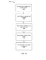
claim 1 and a system according toclaim 6. Preferred embodiments are defined in the dependent claims. - The present invention provides a method of operation of a navigation system including: generating a maneuver instruction for a driving maneuver, the maneuver instruction including an explanation of how to turn, merge, park or operate a driver's vehicle; monitoring a maneuver attempt for a compliance to the maneuver instruction; modifying the maneuver instruction based on the maneuver attempt; assigning a driver skill grade for the maneuver attempt based on the compliance to the maneuver instruction; and generating a training feedback to improve the driver skill grade of the maneuver attempt for displaying on a device.
- The present invention provides a navigation system, including: an instruction module, for generating a maneuver instruction for a driving maneuver, the maneuver instruction including an explanation of how to turn, merge, park or operate a driver's vehicle; a monitor module, coupled to the instruction module, for monitoring a maneuver attempt for a compliance to the maneuver instruction; a modify module, coupled to the monitor module, for modifying the maneuver instruction based on the maneuver attempt; a grade module, coupled to the modify module, for assigning a driver skill grade for the maneuver attempt based on the compliance to the maneuver instruction; and a feedback module, coupled to the grade module, for generating a training feedback to improve the driver skill grade of the maneuver attempt for displaying on a device.
- Certain embodiments of the invention have other steps or elements in addition to or in place of those mentioned above. The steps or elements will become apparent to those skilled in the art from a reading of the following detailed description when taken with reference to the accompanying drawings.
-
-
FIG. 1 is a navigation system with maneuver attempt training mechanism in an embodiment of the present invention. -
FIG. 2 is a first example of a display interface of the first device. -
FIG. 3 is a second example of the display interface. -
FIG. 4 is a third example of the display interface. -
FIG. 5 is an exemplary block diagram of the navigation system. -
FIG. 6 is a control flow of the navigation system. -
FIG. 7 is a detailed view of the path module. -
FIG. 8 is a detailed view of the training module. -
FIG. 9 is a detailed view of the modify module. -
FIG. 10 is a flow chart of a method of operation of the navigation system in a further embodiment of the present invention. - The following embodiments are described in sufficient detail to enable those skilled in the art to make and use the invention. It is to be understood that other embodiments would be evident based on the present disclosure, and that system, process, or mechanical changes may be made without departing from the scope of the present invention.
- In the following description, numerous specific details are given to provide a thorough understanding of the invention. However, it will be apparent that the invention may be practiced without these specific details. In order to avoid obscuring the present invention, some well-known circuits, system configurations, and process steps are not disclosed in detail.
- The drawings showing embodiments of the system are semi-diagrammatic and not to scale and, particularly, some of the dimensions are for the clarity of presentation and are shown exaggerated in the drawing FIGs. Similarly, although the views in the drawings for ease of description generally show similar orientations, this depiction in the FIGs. is arbitrary for the most part. Generally, the invention can be operated in any orientation. The embodiments have been numbered first embodiment, second embodiment, etc. as a matter of descriptive convenience and are not intended to have any other significance or provide limitations for the present invention.
- One skilled in the art would appreciate that the format with which navigation information is expressed is not critical to some embodiments of the invention. For example, in some embodiments, navigation information is presented in the format of (X, Y), where X and Y are two ordinates that define the geographic location, i.e., a position of a user.
- The term "relevant information" referred to herein comprises the navigation information described as well as information relating to points of interest to the user, such as local business, hours of businesses, types of businesses, advertised specials, traffic information, maps, local events, and nearby community or personal information.
- The term "module" referred to herein can include software, hardware, or a combination thereof. For example, the software can be machine code, firmware, embedded code, and application software. Also for example, the hardware can be circuitry, processor, computer, integrated circuit, integrated circuit cores, a pressure sensor, an inertial sensor, a microelectromechanical system (MEMS), passive devices, or a combination thereof.
- Referring now to
FIG. 1 , therein is shown anavigation system 100 with maneuver attempt training mechanism in an embodiment of the present invention. Thenavigation system 100 includes afirst device 102, such as a client or a server, connected to asecond device 106, such as a client or server, with acommunication path 104, such as a wireless or wired network. - For example, the
first device 102 can be of any of a variety of mobile devices, such as a cellular phone, personal digital assistant, a notebook computer, automotive telemetric navigation system, or other multi-functional mobile communication or entertainment device. Thefirst device 102 can be a standalone device, or can be incorporated with a vehicle, for example a car, truck, bus, or train. Thefirst device 102 can couple to thecommunication path 104 to communicate with thesecond device 106. - For illustrative purposes, the
navigation system 100 is described with thefirst device 102 as a mobile computing device, although it is understood that thefirst device 102 can be different types of computing devices. For example, thefirst device 102 can also be a non-mobile computing device, such as a server, a server farm, or a desktop computer. - The
second device 106 can be any of a variety of centralized or decentralized computing devices. For example, thesecond device 106 can be a computer, grid computing resources, a virtualized computer resource, cloud computing resource, routers, switches, peer-to-peer distributed computing devices, or a combination thereof. - The
second device 106 can be centralized in a single computer room, distributed across different rooms, distributed across different geographical locations, embedded within a telecommunications network. Thesecond device 106 can have a means for coupling with thecommunication path 104 to communicate with thefirst device 102. Thesecond device 106 can also be a client type device as described for thefirst device 102. - In another example, the
first device 102 can be a particularized machine, such as a mainframe, a server, a cluster server, rack mounted server, or a blade server, or as more specific examples, an IBM System z10 (TM) Business Class mainframe or a HP ProLiant ML (TM) server. Yet another example, thesecond device 106 can be a particularized machine, such as a portable computing device, a thin client, a notebook, a netbook, a smartphone, personal digital assistant, or a cellular phone, and as specific examples, an Apple iPhone (TM), Palm Centro (TM), or Moto Q Global (TM). - For illustrative purposes, the
navigation system 100 is described with thesecond device 106 as a non-mobile computing device, although it is understood that thesecond device 106 can be different types of computing devices. For example, thesecond device 106 can also be a mobile computing device, such as notebook computer, another client device, or a different type of client device. Thesecond device 106 can be a standalone device, or can be incorporated with a vehicle, for example a car, truck, bus, or train. - Also for illustrative purposes, the
navigation system 100 is shown with thesecond device 106 and thefirst device 102 as end points of thecommunication path 104, although it is understood that thenavigation system 100 can have a different partition between thefirst device 102, thesecond device 106, and thecommunication path 104. For example, thefirst device 102, thesecond device 106, or a combination thereof can also function as part of thecommunication path 104. - The
communication path 104 can be a variety of networks. For example, thecommunication path 104 can include wireless communication, wired communication, optical, ultrasonic, or the combination thereof. Satellite communication, cellular communication, Bluetooth, Infrared Data Association standard (IrDA), wireless fidelity (WiFi), and worldwide interoperability for microwave access (WiMAX) are examples of wireless communication that can be included in thecommunication path 104. Ethernet, digital subscriber line (DSL), fiber to the home (FTTH), and plain old telephone service (POTS) are examples of wired communication that can be included in thecommunication path 104. - Further, the
communication path 104 can traverse a number of network topologies and distances. For example, thecommunication path 104 can include direct connection, personal area network (PAN), local area network (LAN), metropolitan area network (MAN), wide area network (WAN) or any combination thereof. - Referring now to
FIG. 2 , therein is shown a first example of adisplay interface 202 of thefirst device 102. Thedisplay interface 202 can depict a driver'svehicle 204 making a left turn. The driver'svehicle 204 is defined as a vehicle equipped with thefirst device 102, such as a portable or built in navigation system. - A driving
maneuver 206 is defined as the act of steering, maneuvering, or operating a vehicle to interact with the road or traffic. The drivingmaneuver 206 can include operating or maneuvering the driver's vehicle in a left turn, a right turn, U-turn, lane-changes, reversing, merging, and yielding to traffic. The drivingmaneuver 206 can also include operating the driver'svehicle 204 to park including parallel parking, parking on a hill, and parking in a straight parking spot from a turn. - A
turn maneuver 208 is defined as the drivingmaneuver 206 that involves a turn. For example, theturn maneuver 208 can include a right turn, a left turn, a U-turn, and a three-point turn. - A
travel route 210 is defined as a course, path, or way for navigating to a destination. Thenavigation system 100 can generate thetravel route 210 for a driver to travel from one location to another location. Thetravel route 210 from one location to another location can include the drivingmaneuver 206 such as turns, curves, merges, lane-changes, and parking at the end of thetravel route 210. - A
practice route 211 is defined as a course, path, or way that is generated for the driver to practice specific examples of the drivingmaneuver 206. Thepractice route 211 is not used for navigating to a destination but is used to practice different examples of the drivingmaneuver 206. For example, the driver can use thepractice route 211 to practice a series of right and left turns, U-turns, merges, yields, lane changes, or a combination thereof. - A
maneuver instruction 212 is defined as an instruction to perform the drivingmaneuver 206. For example, themaneuver instruction 212 can include guidance on completing the drivingmaneuver 206. For example, thenavigation system 100 can instruct the driver to complete a left turn: "begin slowly turning the steering wheel left as you proceed into the intersection at twenty miles per hour" as an audio instruction. - The
maneuver instruction 212 can be modeled after recommendations and recorded performances from professional driving instructors. For example, themaneuver instruction 212 can be instructions based on how a professional driving instructor would perform the drivingmaneuver 206. - The
maneuver instruction 212 for the drivingmaneuver 206 can include instructions for where to position the vehicle during the drivingmaneuver 206. Themaneuver instruction 212 can also include instructions on how fast the vehicle should be traveling during the drivingmaneuver 206. Themaneuver instruction 212 can also include instructions on when to gear shifts, steering techniques and braking technique during the drivingmaneuver 206. - The
maneuver instruction 212 can be instructions in text or audio prompts. Themaneuver instruction 212 can include instruction and guidance on vehicle speed, steering, trailing distance between cars, and braking. Thenavigation system 100 can also generate themaneuver instruction 212 to have more detail or less detail based on the experience of the driver. - A brand new driver, an intermediate level driver, and an expert driver can receive a different version of the
maneuver instruction 212 with different content that is customized to the driver's experience level. Themaneuver instruction 212 for the expert driver can include instructions on advanced driving techniques. For example, themaneuver instruction 212 for expert drivers can include instructions on how to position the vehicle in a sharp turn at the fastest speed possible. - The
navigation system 100 can adjust the frequency and pace of communicating themaneuver instruction 212 to the driver. A novice driver can receive more or less instructions based on the comfort level of the driver. For example, thenavigation system 100 can deliver a less detailed version of themaneuver instruction 212 to the novice driver to avoid distracting the driver as the driver focuses on learning to drive. - The
maneuver instruction 212 can include abasic instruction 214 and a location-specific instruction 216. Thebasic instruction 214 is defined as a general instruction for all maneuvers of the same type such as instructions that apply to all left turns. For example, thebasic instruction 214 for all left turns can include: "Please continue, remaining in your lane. Gradually reduce speed before the start of the turn. Begin turning the steering wheel to the left". - The location-
specific instruction 216 is defined as themaneuver instruction 212 specifically generated for the drivingmaneuver 206 at a specific location on thetravel route 210. For example, the location-specific instruction 216 can be generated for a specific left turn at the corner of "Main Street and Second Street while heading north". Thenavigation system 100 can use navigation and geographic information from thetravel route 210 to generate the location-specific instruction 216. - For example, the
navigation system 100 can identify location-specific geographic features for the specific left turn and incorporate the features into themaneuver instruction 212. If the left turn at "Main Street" includes a center turn lane, the location-specific instruction 216 can instruct the driver to pull into the center turn lane as one of the instructions for completing the left turn at "Main Street". - A
lesson request 218 is defined as a request for a specific type of the drivingmaneuver 206. For example, the driver can input thelesson request 218 for left turns. Thenavigation system 100 can generate themaneuver instruction 212 of a left-turn for the driver to practice left turns. The driver can also request parallel parking as thelesson request 218. Thenavigation system 100 can generate themaneuver instruction 212 of parallel parking for the driver to practice. - A
maneuver attempt 222 is defined as the driver's performance of the drivingmaneuver 206. Thenavigation system 100 can monitor themaneuver attempt 222 and identify how the performance of themaneuver attempt 222 conformed to themaneuver instruction 212. For example, themaneuver instruction 212 can instruct the driver to approach a turn at fifteen to twenty miles per hour. The driver can approach the turn at fifty miles per hour. Thenavigation system 100 can assign adriver skill grade 224 to themaneuver attempt 222 based on how much themaneuver attempt 222 deviated from the guidelines of themaneuver instruction 212. - The
driver skill grade 224 is defined as a grade or rating assigned to themaneuver attempt 222. Thedriver skill grade 224 can include the grades of "A", "B", "C", "D", and "F" as examples of grades. Thedriver skill grade 224 can be based on how closely themaneuver attempt 222 conformed to the instructions and guidelines of themaneuver instruction 212 for each stage of the drivingmaneuver 206. - For example, if the
maneuver attempt 222 conformed to the guidelines and instructions from themaneuver instruction 212, thedriver skill grade 224 can be "A", "B", or "C". In this example, the driver could have conformed to the recommended speed and performed all the steps included in themaneuver instruction 212. If themaneuver attempt 222 deviated or failed to complete the instructions from themaneuver instruction 212, thedriver skill grade 224 for themaneuver attempt 222 can be "D" or "F". - A
compliance 226 is defined as a situation where themaneuver attempt 222 satisfies predetermined minimal requirements or mandatory steps of themaneuver instruction 212 for the drivingmaneuver 206. For example, themaneuver instruction 212 can include mandatory steps and optional steps for completing a left turn. Thecompliance 226 to themaneuver instruction 212 occurs when the driver completes the mandatory steps of themaneuver instruction 212. - An example of a mandatory step can be to make a complete stop at a red light. An example of an optional step can be to slow down to twenty miles per hour during a turn. The driver's completion of mandatory steps and optional steps can determine the
driver skill grade 224 for themaneuver attempt 222 and thecompliance 226. - For example, the
driver skill grade 224 of "A", "B", and "C" for themaneuver attempt 222 can represent thecompliance 226 of themaneuver instruction 212. If the driver completed all of the mandatory steps and optional steps of themaneuver instruction 212 with only slight deviations during themaneuver attempt 222, thenavigation system 100 can assign thedriver skill grade 224 of "A" to themaneuver attempt 222. Thedriver skill grade 224 of "A" qualifies as thecompliance 226. - If a driver fails to complete a mandatory step of the
maneuver instruction 212, thenavigation system 100 can assign thedriver skill grade 224 of "D" or "F". Thedriver skill grade 224 of "D" or "F" does not qualify as thecompliance 226 to themaneuver instruction 212. - For example, the
maneuver instruction 212 for a left turn can be to maintain at least a ten miles per hour speed during the maneuver. The driver can make a complete stop in the middle of an intersection while attempting the left turn. Themaneuver attempt 222 of the left turn can be assigned thedriver skill grade 224 of "F" because the driver failed to maintain at least a ten miles per hour speed and the driver created a hazardous situation in the middle of the intersection. - The
compliance 226 can be used to inform the driver that the drivingmaneuver 206 was completed safely and successfully at the minimal requirements of themaneuver instruction 212. Thedriver skill grade 224 can inform the driver on how to further improve themaneuver attempt 222. - For example, an inexperienced driver can receive the
driver skill grade 224 of "C" and still pass the minimal requirements of themaneuver instruction 212. Although thecompliance 226 indicates that the driver successfully completed the drivingmaneuver 206, thedriver skill grade 224 of "C" can inform the driver that the driver can improve their performance of the drivingmaneuver 206. The driver can practice the drivingmaneuver 206 to attempt to receive thedriver skill grade 224 of "B" or "A" in thenext maneuver attempt 222. - Referring now to
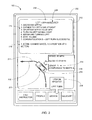
FIG. 3 , therein is shown a second example of thedisplay interface 202. Thedisplay interface 202 can depict the driver'svehicle 204 traveling north along aroad 302. Thedisplay interface 202 can also depict an unprotectedleft turn 304 and a three-way stop 306. Thedisplay interface 202 also depicts the driver'svehicle 204 following thetravel route 210 toward the unprotectedleft turn 304. - The unprotected
left turn 304 is defined as a left turn at an intersection without a left turn signal light. Vehicle's making the unprotectedleft turn 304 can make a left turn after oncoming traffic has passed through the traffic intersection. The three-way stop 306 is defined as a three-way intersection with stop signs at each intersection. Vehicles at an intersection with the three-way stop 306 must stop at one of the stop signs before traveling straight or turning at the three-way stop 306. - A
maneuver difficulty 308 is defined as a difficulty rating for the drivingmaneuver 206. For example, themaneuver difficulty 308 for the drivingmaneuver 206 ofFIG. 2 can be rated or classified as "hard", "medium", and "easy". - For example, the
display interface 202 depicts the unprotectedleft turn 304. Themaneuver difficulty 308 of the unprotectedleft turn 304 can be rated or classified as "hard" because of the dangers associated with making the unprotectedleft turn 304 against oncoming traffic. Many vehicles accidents occur at intersections with the unprotectedleft turn 304 because drivers can make a left turn into oncoming traffic and drivers do not check if the intersection is clear of traffic before making the turn. - Further, for example, the driving
maneuver 206 of merging onto a crowded freeway with a short acceleration onramp can be rated as "hard" for themaneuver difficulty 308. The drivingmaneuver 206 of parallel parking can also be an example of the drivingmaneuver 206 with "hard" as themaneuver difficulty 308. Themaneuver difficulty 308 can be based on the driver skill needed to complete the maneuver and the chances of hitting another vehicle or object during the maneuver. - The
maneuver difficulty 308 of the three-way stop 306 can be rated or classified as "easy" because the driver'svehicle 204 is protected by the stop sign when turning left. The drivingmaneuver 206 of parking in a slanted parking spot can also be rated as "easy" for themaneuver difficulty 308 because the maneuver requires less skill to complete than a straight parking spot. Themaneuver difficulty 308 of the drivingmaneuver 206 can also be based on user-generated ratings for the drivingmaneuver 206 and historical statistics about the drivingmaneuver 206. - A
dangerous situation 310 is defined as a driving situation that may cause an accident or perhaps too difficult for the driver to complete successfully. For example, the unprotectedleft turn 304 can be thedangerous situation 310 because of the risks of collision with oncoming traffic. - A
detour 312 is defined as an indirect way or course from thetravel route 210. Thenavigation system 100 can generate thedetour 312 to thetravel route 210 to avoid thedangerous situation 310. Thenavigation system 100 can also generate thedetour 312 to avoid the drivingmaneuver 206 with themaneuver difficulty 308 that is beyond the skill of the driver of thenavigation system 100. - For example, a novice driver could have received an "F" for the
driver skill grade 224 ofFIG. 2 for the drivingmaneuver 206 for the unprotectedleft turn 304. Thenavigation system 100 can identify themaneuver difficulty 308 of the unprotectedleft turn 304 as "hard" and identify that the novice driver has an "F" for the drivingmaneuver 206. - The
navigation system 100 can determine that the unprotectedleft turn 304 is thedangerous situation 310 because of themaneuver difficulty 308 and thedriver skill grade 224 for the drivingmaneuver 206. Thenavigation system 100 can generate thedetour 312 to the three-way stop 306 to avoid thedangerous situation 310. Thenavigation system 100 can increase the safety of driving conditions by routing inexperienced drivers around thedangerous situation 310. - A
training feedback 314 is defined as suggestions, recommendations, or feedback for the driver to improve the driver's performance of the drivingmaneuver 206. For example, the driver can receive thedriver skill grade 224 after completing the drivingmaneuver 206. Thetraining feedback 314 can be suggestions or recommendations for the driver to follow to improve thedriver skill grade 224 for the next time that the driver attempts the drivingmaneuver 206. - For example, the
training feedback 314 can suggest to the driver to reduce the speed of the vehicle when attempting the drivingmaneuver 206 of turning left at an intersection. Thetraining feedback 314 can inform the driver how themaneuver attempt 222 ofFIG. 2 is deviating from themaneuver instruction 212 and provide an explanation of the assignment of thedriver skill grade 224 for the drivingmaneuver 206 to the driver. The driver can study thetraining feedback 314 and follow the suggestions in subsequent attempts at the drivingmaneuver 206 to improve thedriver skill grade 224 for the drivingmaneuver 206. - The
navigation system 100 can generate and modify themaneuver instruction 212 ofFIG. 2 at different stages of the drivingmaneuver 206. For example, the drivingmaneuver 206 can include an approachingstage 316, an enteringstage 318, amiddle stage 320, and anend stage 322 for different stages during the drivingmaneuver 206. - The approaching
stage 316 is defined as the time period before the driver'svehicle 204 reaches the drivingmaneuver 206. For example, the approachingstage 316 for a turn can be the time period before the driver must begin turning the steering wheel to enter the turn. - The entering
stage 318 is defined as the time period when the driver'svehicle 204 enters the drivingmaneuver 206. For example, the enteringstage 318 for the drivingmaneuver 206 of parallel parking can be when the driver'svehicle 204 pulls up parallel to the other vehicle to begin parallel parking. - The
middle stage 320 is defined as the time period after the driver'svehicle 204 has entered the drivingmaneuver 206. For example, themiddle stage 320 can be the time period after entering a turn where the driver'svehicle 204 should accelerate to exit the turn. Theend stage 322 is defined as the time period after the driver'svehicle 204 has concluded the drivingmaneuver 206. - Referring now to
FIG. 4 , therein is shown a third example of thedisplay interface 202. Thedisplay interface 202 depicts the driver'svehicle 204 attempting the drivingmaneuver 206 ofFIG. 2 of parallel parking. Parallel parking is an example of aparking maneuver 402. - The
parking maneuver 402 is defined as the drivingmaneuver 206 of parking. For example, theparking maneuver 402 can include: parallel parking, parking in a parking spot without turning, turning into a straight parking spot, turning into a slanted parking spot, and reversing into a parking spot. - A
vehicle direction 404 is defined as the course or direction towards which the driver'svehicle 204 is traveling. Thevehicle direction 404 can be indicated in terms of a three hundred and sixty degree scale with zero degrees indicating that the vehicle is facing north. Thevehicle direction 404 can be used to assist drivers in steering the vehicle and thevehicle direction 404 can be displayed on thedisplay interface 202. Thevehicle direction 404 is similar to the current heading of the vehicle and thevehicle direction 404 also includes the direction that the vehicle is traveling when the vehicle is traveling in reverse. - The
maneuver instruction 212 ofFIG. 2 can be modified based on different components or attributes of performing the drivingmaneuver 206. For example, the different components of driving can include: the vehicle's position during the maneuver, the vehicle's speed, gear shifting, steering and braking. Themaneuver instruction 212 can include aposition recommendation 406, aspeed recommendation 408, agear shift recommendation 410, asteering recommendation 412, and abraking recommendation 414 as the different components of driving. - The
position recommendation 406 is defined as instructions that modify themaneuver instruction 212 on the positioning of thevehicle direction 404 during the drivingmaneuver 206 to successfully complete the drivingmaneuver 206. For example, theposition recommendation 406 can be instructions on where to position the driver'svehicle 204 at the approachingstage 316, the enteringstage 318, themiddle stage 320, and theend stage 322 ofFIG. 3 . Theposition recommendation 406 can be audio instructions, text instruction, or a combination thereof. - The
position recommendation 406 can be communicated to the driver as a graphical representation of the position of the driver'svehicle 204 in relation to the street and nearby objects on thedisplay interface 202. For example, theposition recommendation 406 can be an animation of a model of the driver'svehicle 204 performing the drivingmaneuver 206 on thedisplay interface 202. The animation of theposition recommendation 406 can display the position of the driver'svehicle 204 in relationship to the road during the drivingmaneuver 206. The driver can also listen to audio instructions from thenavigation system 100 and model themaneuver attempt 222 ofFIG. 2 based on what is seen on thedisplay interface 202. - The
speed recommendation 408 is defined as instructions that modify themaneuver instruction 212 on the recommend speed for a vehicle during the drivingmaneuver 206. Themaneuver instruction 212 can instruct the driver to enter the drivingmaneuver 206 at thirty miles per hour but the driver can be entering the maneuver below the recommended speed. Thespeed recommendation 408 can modify themaneuver instruction 212 for the driver to speed up or to slow down for the next stage of the drivingmaneuver 206. - For example, the vehicle's speed at the approaching
stage 316 can be ten miles below the recommendation from themaneuver instruction 212. Thespeed recommendation 408 at the enteringstage 318 can be instructions to increase the vehicle's speed by ten miles an hour as the vehicle transitions to the enteringstage 318 of the drivingmaneuver 206. - Further, for example, the
speed recommendation 408 can be "five miles per hour" for the drivingmaneuver 206 of parallel parking. If the driver'svehicle 204 is traveling at "fifteen miles per hour" in an attempt to parallel park, thespeed recommendation 408 can be to slow down to "immediately reduce speed to five miles per hour". - The
gear shift recommendation 410 is defined as instructions that modify themaneuver instruction 212 on gear shift timing of the driver'svehicle 204 during the drivingmaneuver 206. For example, the driver can deviate from the recommendations from themaneuver instruction 212 when shifting gears. The driver can shift into reverse for parallel parking before arriving in the correct position to begin the drivingmaneuver 206. - Further, for example, the driver can be downshifting or upshifting a manual transmission vehicle at inefficient times during the driving
maneuver 206 such as a turn. Thegear shift recommendation 410 can be a prompt based on the revolutions per minute of the vehicle's engine to shift gears based on themaneuver attempt 222. Thegear shift recommendation 410 can also be instructions to downshift and slow down the vehicle during the enteringstage 318 of a turn based on the vehicles speed when approaching the drivingmaneuver 206. - The
steering recommendation 412 is defined as instructions that modify themaneuver instruction 212 on steering the driver'svehicle 204 during the drivingmaneuver 206. For example, thesteering recommendation 412 can be instructions on how far to turn the steering wheel during theparking maneuver 402 of parallel parking. Themaneuver instruction 212 can instruct the driver to turn the steering wheel so that thevehicle direction 404 of the vehicle is one hundred and forty degrees. The driver can turn the steering wheel to one hundred degrees and begin theparking maneuver 402. Thesteering recommendation 412 can instruct the driver to turn the steering wheel an additional forty degrees before attempting the maneuver. - Further, for example, the
steering recommendation 412 can be instructions on which direction to turn the steering vehicle of the driver'svehicle 204 when in reverse gear. Thesteering recommendation 412 can also instruct the driver of on how to steer the vehicle through high speed turns and curves to avoid under-steer of the vehicle or over-steer of the vehicle during theturn maneuver 208 ofFIG. 2 . - Under-steer is a handling characteristic of an automotive vehicle that causes it to turn less sharply than the driver intends because the front wheels slide to the outside of the turn before the rear wheels lose traction. Over-steer is the handling of an automotive vehicle that causes turns that are sharper than the driver intends because the rear wheels slide to the outside of the turn before the front wheels lose traction. Both under-steer and over-steer can be corrected by turning the steering wheel to compensate for loss of traction. The
navigation system 100 can give instructions on how to turn the steering wheel during these situations. - The
braking recommendation 414 is defined as instructions that further modify themaneuver instruction 212 on braking during the drivingmaneuver 206. For example, thebraking recommendation 414 can be instructions on when to start braking for the drivingmaneuver 206 of a sharp turn at a high speed. Thebraking recommendation 414 can be to "gently tap the brakes" or "to press firmly on the brakes". Further, for example, thebraking recommendation 414 can be at the approachingstage 316, the enteringstage 318, themiddle stage 320, and theend stage 322 of theturn maneuver 208 to help complete the turn. - Referring now to
FIG. 5 , therein is shown an exemplary block diagram of thenavigation system 100. Thefirst device 102 can send information in afirst device transmission 508 over thecommunication path 104 to thesecond device 106. Thesecond device 106 can send information in asecond device transmission 510 over thecommunication path 104 to thefirst device 102. - For illustrative purposes, the
navigation system 100 is shown with thefirst device 102 as a client device, although it is understood that thenavigation system 100 can have thefirst device 102 as a different type of device. For example, thefirst device 102 can be a server. - Also for illustrative purposes, the
navigation system 100 is shown with thesecond device 106 as a server, although it is understood that thenavigation system 100 can have thesecond device 106 as a different type of device. For example, thesecond device 106 can be a client device. - For brevity of description in this embodiment of the present invention, the
first device 102 will be described as a client device and thesecond device 106 will be described as a server device. The present invention is not limited to this selection for the type of devices. The selection is an example of the present invention. - The
first device 102 can include afirst control unit 512, afirst storage unit 514, afirst communication unit 516, a first user interface 518, and afirst location unit 520. Thefirst device 102 ofFIG. 5 can be similarly described by thefirst device 102 ofFIG. 1 . - The
first control unit 512 can include afirst control interface 522. Thefirst control unit 512 can execute afirst software 526 to provide the intelligence of thenavigation system 100. Thefirst control unit 512 can be implemented in a number of different manners. For example, thefirst control unit 512 can be a processor, an embedded processor, a microprocessor, a hardware control logic, a hardware finite state machine (FSM), a digital signal processor (DSP), or a combination thereof. Thefirst control interface 522 can be used for communication between thefirst control unit 512 and other functional units in thefirst device 102. Thefirst control interface 522 can also be used for communication that is external to thefirst device 102. - The
first control interface 522 can receive information from the other functional units or from external sources, or can transmit information to the other functional units or to external destinations. The external sources and the external destinations refer to sources and destinations external to thefirst device 102. - The
first control interface 522 can be implemented in different ways and can include different implementations depending on which functional units or external units are being interfaced with thefirst control interface 522. For example, thefirst control interface 522 can be implemented with a pressure sensor, an inertial sensor, a microelectromechanical system (MEMS), optical circuitry, waveguides, wireless circuitry, wireline circuitry, or a combination thereof. - The
first location unit 520 can generate location information, current heading, and current speed of thefirst device 102, as examples. Thefirst location unit 520 can be implemented in many ways. For example, thefirst location unit 520 can function as at least a part of a global positioning system (GPS), an inertial navigation system, a cellular-tower location system, a pressure location system, or any combination thereof. - The
first location unit 520 can include afirst location interface 532. Thefirst location interface 532 can be used for communication between thefirst location unit 520 and other functional units in thefirst device 102. Thefirst location interface 532 can also be used for communication that is external to thefirst device 102. - The
first location interface 532 can receive information from the other functional units or from external sources, or can transmit information to the other functional units or to external destinations. The external sources and the external destinations refer to sources and destinations external to thefirst device 102. - The
first location interface 532 can include different implementations depending on which functional units or external units are being interfaced with thefirst location unit 520. Thefirst location interface 532 can be implemented with technologies and techniques similar to the implementation of thefirst control interface 522. - The
first storage unit 514 can store thefirst software 526. Thefirst storage unit 514 can also store the relevant information, such as advertisements, points of interest (POI), navigation routing entries, or any combination thereof. - The
first storage unit 514 can be a volatile memory, a nonvolatile memory, an internal memory, an external memory, or a combination thereof. For example, thefirst storage unit 514 can be a nonvolatile storage such as non-volatile random access memory (NVRAM), Flash memory, disk storage, or a volatile storage such as static random access memory (SRAM). - The
first storage unit 514 can include afirst storage interface 524. Thefirst storage interface 524 can be used for communication between thefirst location unit 520 and other functional units in thefirst device 102. Thefirst storage interface 524 can also be used for communication that is external to thefirst device 102. - The
first storage interface 524 can receive information from the other functional units or from external sources, or can transmit information to the other functional units or to external destinations. The external sources and the external destinations refer to sources and destinations external to thefirst device 102. - The
first storage interface 524 can include different implementations depending on which functional units or external units are being interfaced with thefirst storage unit 514. Thefirst storage interface 524 can be implemented with technologies and techniques similar to the implementation of thefirst control interface 522. - The
first communication unit 516 can enable external communication to and from thefirst device 102. For example, thefirst communication unit 516 can permit thefirst device 102 to communicate with thesecond device 106 ofFIG. 1 , an attachment, such as a peripheral device or a computer desktop, and thecommunication path 104. - The
first communication unit 516 can also function as a communication hub allowing thefirst device 102 to function as part of thecommunication path 104 and not limited to be an end point or terminal unit to thecommunication path 104. Thefirst communication unit 516 can include active and passive components, such as microelectronics or an antenna, for interaction with thecommunication path 104. - The
first communication unit 516 can include afirst communication interface 528. Thefirst communication interface 528 can be used for communication between thefirst communication unit 516 and other functional units in thefirst device 102. Thefirst communication interface 528 can receive information from the other functional units or can transmit information to the other functional units. - The
first communication interface 528 can include different implementations depending on which functional units are being interfaced with thefirst communication unit 516. Thefirst communication interface 528 can be implemented with technologies and techniques similar to the implementation of thefirst control interface 522. - The first user interface 518 allows a user (not shown) to interface and interact with the
first device 102. The first user interface 518 can include an input device and an output device. Examples of the input device of the first user interface 518 can include a keypad, a touchpad, soft-keys, a keyboard, a microphone, or any combination thereof to provide data and communication inputs. - The first user interface 518 can include a
first display interface 530. Examples of thefirst display interface 530 can include thedisplay interface 202 ofFIG. 2 . Thefirst display interface 530 can include a display, a projector, a video screen, a speaker, or any combination thereof. The screenshot shown on thedisplay interface 202 described inFIG. 2 can represent an example of a screenshot for thenavigation system 100. - The
first control unit 512 can operate the first user interface 518 to display information generated by thenavigation system 100. Thefirst control unit 512 can also execute thefirst software 526 for the other functions of thenavigation system 100, including receiving location information from thefirst location unit 520. Thefirst control unit 512 can further execute thefirst software 526 for interaction with thecommunication path 104 via thefirst communication unit 516. - The
second device 106 can be optimized for implementing the present invention in a multiple device embodiment with thefirst device 102. Thesecond device 106 can provide the additional or higher performance processing power compared to thefirst device 102. Thesecond device 106 can include asecond control unit 534, asecond communication unit 536, asecond user interface 538, and asecond location unit 552. - The
second user interface 538 allows a user (not shown) to interface and interact with thesecond device 106. Thesecond user interface 538 can include an input device and an output device. Examples of the input device of thesecond user interface 538 can include a keypad, a touchpad, soft-keys, a keyboard, a microphone, or any combination thereof to provide data and communication inputs. Examples of the output device of thesecond user interface 538 can include asecond display interface 540. Thesecond display interface 540 can include a display, a projector, a video screen, a speaker, or any combination thereof. - The
second control unit 534 can execute asecond software 542 to provide the intelligence of thesecond device 106 of thenavigation system 100. Thesecond software 542 can operate in conjunction with thefirst software 526. Thesecond control unit 534 can provide additional performance compared to thefirst control unit 512. - The
second control unit 534 can operate thesecond user interface 538 to display information. Thesecond control unit 534 can also execute thesecond software 542 for the other functions of thenavigation system 100, including operating thesecond communication unit 536 to communicate with thefirst device 102 over thecommunication path 104. - The
second control unit 534 can be implemented in a number of different manners. For example, thesecond control unit 534 can be a processor, an embedded processor, a microprocessor, a hardware control logic, a hardware finite state machine (FSM), a digital signal processor (DSP), or a combination thereof. - The
second control unit 534 can include asecond controller interface 544. Thesecond controller interface 544 can be used for communication between thesecond control unit 534 and other functional units in thesecond device 106. Thesecond controller interface 544 can also be used for communication that is external to thesecond device 106. - The
second controller interface 544 can receive information from the other functional units or from external sources, or can transmit information to the other functional units or to external destinations. The external sources and the external destinations refer to sources and destinations external to thesecond device 106. - The
second controller interface 544 can be implemented in different ways and can include different implementations depending on which functional units or external units are being interfaced with thesecond controller interface 544. For example, thesecond controller interface 544 can be implemented with a pressure sensor, an inertial sensor, a microelectromechanical system (MEMS), optical circuitry, waveguides, wireless circuitry, wireline circuitry, or a combination thereof. - A
second storage unit 546 can store thesecond software 542. Thesecond storage unit 546 can also store the relevant information, such as advertisements, points of interest (POI), navigation routing entries, or any combination thereof. Thesecond storage unit 546 can be sized to provide the additional storage capacity to supplement thefirst storage unit 514. - For illustrative purposes, the
second storage unit 546 is shown as a single element, although it is understood that thesecond storage unit 546 can be a distribution of storage elements. Also for illustrative purposes, thenavigation system 100 is shown with thesecond storage unit 546 as a single hierarchy storage system, although it is understood that thenavigation system 100 can have thesecond storage unit 546 in a different configuration. For example, thesecond storage unit 546 can be formed with different storage technologies forming a memory hierarchal system including different levels of caching, main memory, rotating media, or off-line storage. - The
second storage unit 546 can be a volatile memory, a nonvolatile memory, an internal memory, an external memory, or a combination thereof. For example, thesecond storage unit 546 can be a nonvolatile storage such as non-volatile random access memory (NVRAM), Flash memory, disk storage, or a volatile storage such as static random access memory (SRAM). - The
second storage unit 546 can include asecond storage interface 548. Thesecond storage interface 548 can be used for communication between thefirst location unit 520 and other functional units in thesecond device 106. Thesecond storage interface 548 can also be used for communication that is external to thesecond device 106. - The
second storage interface 548 can receive information from the other functional units or from external sources, or can transmit information to the other functional units or to external destinations. The external sources and the external destinations refer to sources and destinations external to thesecond device 106. - The
second storage interface 548 can include different implementations depending on which functional units or external units are being interfaced with thesecond storage unit 546. Thesecond storage interface 548 can be implemented with technologies and techniques similar to the implementation of thesecond controller interface 544. - The
second communication unit 536 can enable external communication to and from thesecond device 106. For example, thesecond communication unit 536 can permit thesecond device 106 to communicate with thefirst device 102 over thecommunication path 104. - The
second communication unit 536 can also function as a communication hub allowing thesecond device 106 to function as part of thecommunication path 104 and not limited to be an end point or terminal unit to thecommunication path 104. Thesecond communication unit 536 can include active and passive components, such as microelectronics or an antenna, for interaction with thecommunication path 104. - The
second communication unit 536 can include asecond communication interface 550. Thesecond communication interface 550 can be used for communication between thesecond communication unit 536 and other functional units in thesecond device 106. Thesecond communication interface 550 can receive information from the other functional units or can transmit information to the other functional units. - The
second communication interface 550 can include different implementations depending on which functional units are being interfaced with thesecond communication unit 536. Thesecond communication interface 550 can be implemented with technologies and techniques similar to the implementation of thesecond controller interface 544. - The
first communication unit 516 can couple with thecommunication path 104 to send information to thesecond device 106 in thefirst device transmission 508. Thesecond device 106 can receive information in thesecond communication unit 536 from thefirst device transmission 508 of thecommunication path 104. - The
second communication unit 536 can couple with thecommunication path 104 to send information to thefirst device 102 in thesecond device transmission 510. Thefirst device 102 can receive information in thefirst communication unit 516 from thesecond device transmission 510 of thecommunication path 104. Thenavigation system 100 can be executed by thefirst control unit 512, thesecond control unit 534, or a combination thereof. - The
second location unit 552 can receive location information, current heading, and current speed of thefirst device 102, as examples. Thesecond location unit 552 can be implemented in many ways. For example, thesecond location unit 552 can function as at least a part of a global positioning system (GPS), an inertial navigation system, a cellular-tower location system, a pressure location system, or any combination thereof. - The
second location unit 552 can include asecond location interface 554. Thesecond location interface 554 can be used for communication between thesecond location unit 552 and other functional units in thefirst device 102. Thesecond location interface 554 can also be used for communication that is external to thesecond device 106. - The
second location interface 554 can receive information from the other functional units or from external sources, or can transmit information to the other functional units or to external destinations. The external sources and the external destinations refer to sources and destinations external to thesecond device 106. - The
second location interface 554 can include different implementations depending on which functional units or external units are being interfaced with thesecond location unit 552. Thesecond location interface 554 can be implemented with technologies and techniques similar to the implementation of thesecond controller interface 544. - For illustrative purposes, the
second device 106 is shown with the partition having thesecond user interface 538, thesecond storage unit 546, thesecond control unit 534, and thesecond communication unit 536, although it is understood that thesecond device 106 can have a different partition. For example, thesecond software 542 can be partitioned differently such that some or all of its function can be in thesecond control unit 534 and thesecond communication unit 536. Also, thesecond device 106 can include other functional units not shown inFIG. 5 for clarity. - The functional units in the
first device 102 can work individually and independently of the other functional units. Thefirst device 102 can work individually and independently from thesecond device 106 and thecommunication path 104. - The functional units in the
second device 106 can work individually and independently of the other functional units. Thesecond device 106 can work individually and independently from thefirst device 102 and thecommunication path 104. - For illustrative purposes, the
navigation system 100 is described by operation of thefirst device 102 and thesecond device 106. It is understood that thefirst device 102 and thesecond device 106 can operate any of the modules and functions of thenavigation system 100. For example, thefirst device 102 is described to operate thefirst location unit 520, although it is understood that thesecond device 106 can also operate thefirst location unit 520. - Referring now to
FIG. 6 , therein is shown a control flow of thenavigation system 100. Thenavigation system 100 can include aprofile module 602, alesson module 604, apath module 606, and atraining module 608. In thenavigation system 100, as an example, each module is indicated by a number and successively higher module numbers follow one another. Control flow can pass from one module to the next higher numbered module unless explicitly otherwise indicated. - The
profile module 602 receives driver experience information about the driver of the driver'svehicle 204 ofFIG. 2 for generating themaneuver instruction 212 ofFIG. 2 . For example, thenavigation system 100 can classify a driver as "beginner", "intermediate", or "expert" based on the driver's performance in prior driving sessions. First time users of thenavigation system 100 can take a driving tutorial and thenavigation system 100 can determine the driver's experience based on the driver's performance of the tutorial. - For example, the
navigation system 100 can generate thepractice route 211 ofFIG. 2 for a driver that is operating thenavigation system 100 for the first time. Thepractice route 211 can be used as a tutorial to evaluate the driver's experience. Thepractice route 211 can include a series of the drivingmaneuver 206 ofFIG. 2 including turns, merges, lane changes, and parking. Thenavigation system 100 can classify the experience of the driver based on thedriver skill grade 224 ofFIG. 2 of themaneuver attempt 222 ofFIG. 2 that were performed on thepractice route 211. - The driver can also skip the tutorial and input an experience level such as "beginner", "intermediate", and "expert" as examples. The
navigation system 100 can use the experience of drivers to generate themaneuver instruction 212 with content that is designed for that experience level. For example, beginner drivers can receive themaneuver instruction 212 that is designed for beginners. - The
profile module 602 can store lesson progress and training history of the driver including thedriver skill grade 224 for the drivingmaneuver 206 ofFIG. 2 . Thenavigation system 100 can track the driver's progress as the driver improves. For example, the driver can complete "beginner" driving tutorials and move on to intermediate level driving lessons. At the intermediate level, the driver can receive themaneuver instruction 212 that is designed for intermediate drivers. - The
lesson module 604 provides lessons for driver training and a driver training curriculum based on the experience level of the driver. Thelesson module 604 also receives thelesson request 218 ofFIG. 2 . For example, the driver can input "beginner" into theprofile module 602 and thelesson module 604 can provide training tutorials on driving fundamentals. Thelesson request 218 can be requests for lessons and tutorials on turning, parking, and other types of the drivingmaneuver 206. - The
path module 606 identifies thevehicle direction 404 ofFIG. 4 and receives geographic information to identify the drivingmaneuver 206 in thetravel route 210 ofFIG. 2 . Thepath module 606 also identifies themaneuver difficulty 308 ofFIG. 3 of the drivingmaneuver 206. - The
path module 606 also generates thepractice route 211 ofFIG. 2 and thedetour 312 ofFIG. 3 . Thepath module 606 can access geographic information, traffic information, GPS information, or a combination thereof to identify the drivingmaneuver 206 in thetravel route 210. Thepath module 606 will be explained in greater detail below. - The
training module 608 generates and modifies themaneuver instruction 212. Thetraining module 608 provides driver training by generating themaneuver instruction 212 for the drivingmaneuver 206. Thetraining module 608 can also modify themaneuver instruction 212 during themaneuver attempt 222 to recommend corrections to the driver's deviations to themaneuver instruction 212. Thetraining module 608 will be explained in greater detail below. - The physical transformation from monitoring the
maneuver attempt 222 and modifying themaneuver instruction 212 based on themaneuver attempt 222 results in movement in the physical world, such as people using thefirst device 102, the vehicle, or a combination thereof, based on the operation of thenavigation system 100. Drivers respond to themaneuver instruction 212 as they perform themaneuver attempt 222 of the drivingmaneuver 206. - The
navigation system 100 monitors themaneuver attempt 222 and modifies themaneuver instruction 212 to give the driver feedback on the driver's performance. As the movement in the physical world occurs, the movement itself creates additional information that is converted back to themaneuver attempt 222 and themaneuver instruction 212 for continued operation of thenavigation system 100 and to continue the movement in the physical world. - The
navigation system 100 can be implemented on thefirst device 102 ofFIG. 5 , on thesecond device 106 ofFIG. 5 , or partitioned between thefirst device 102 and thesecond device 106. Thefirst software 526 ofFIG. 5 of thefirst device 102 can include thenavigation system 100. For example, thefirst software 526 can include theprofile module 602, thelesson module 604, thepath module 606, and thetraining module 608. Thefirst control unit 512 ofFIG. 5 can execute thefirst software 526. - The
first control unit 512 can execute theprofile module 602, thelesson module 604, thepath module 606, and thetraining module 608. Thefirst control unit 512 can execute theprofile module 602 to receive information about the driver. Thefirst control unit 512 can execute thelesson module 604 to receive thelesson request 218. - The
first control unit 512 can execute thepath module 606 to identify thevehicle direction 404 and identify the drivingmaneuver 206 in thetravel route 210. Thefirst control unit 512 can execute thetraining module 608 to generate and modify themaneuver instruction 212. - The
first communication unit 516 ofFIG. 5 can be used by thepath module 606 to receive GPS information and to send and receive navigation information. Thefirst location unit 520 ofFIG. 5 can be used by thepath module 606 to identify thevehicle direction 404. Thefirst display interface 530 ofFIG. 5 can be used by thetraining module 608 to display navigation information. - In an example for the
second device 106 ofFIG. 5 , thesecond software 542 ofFIG. 5 can include thenavigation system 100. For example, thesecond software 542 can include theprofile module 602, thelesson module 604, thepath module 606, and thetraining module 608. Thesecond control unit 534 ofFIG. 5 can execute thesecond software 542. - The
second control unit 534 can execute theprofile module 602, thelesson module 604, thepath module 606, and thetraining module 608. Thesecond control unit 534 can execute theprofile module 602, thelesson module 604, thepath module 606, and thetraining module 608. Thesecond control unit 534 can execute theprofile module 602 to receive information about the driver. Thesecond control unit 534 can execute thelesson module 604 to receive thelesson request 218. - The
second control unit 534 can execute thepath module 606 to identify thevehicle direction 404 and identify the drivingmaneuver 206 in thetravel route 210. Thesecond control unit 534 can execute thetraining module 608 to generate and modify themaneuver instruction 212. - The
second communication unit 536 ofFIG. 5 can be used by thepath module 606 to receive GPS information and to send and receive navigation information. Thesecond location unit 552 ofFIG. 5 can be used by thepath module 606 to identify thevehicle direction 404. Thesecond display interface 540 can be used by thetraining module 608 to display navigation information. - In another example, the
navigation system 100 can be partitioned between thefirst software 526 and thesecond software 542. For example, thefirst software 526 can include thetraining module 608. Thesecond software 542 can include theprofile module 602, thelesson module 604, and thepath module 606. Thesecond control unit 534 can execute modules partitioned on thesecond software 542 and thefirst control unit 512 can execute modules partitioned on thefirst software 526. - The
second control unit 534 can execute theprofile module 602, thelesson module 604, and thepath module 606. Thesecond control unit 534 can execute theprofile module 602 to receive information about the driver. Thesecond control unit 534 can execute thelesson module 604 to receive thelesson request 218. Thesecond control unit 534 can execute thepath module 606 to identify thevehicle direction 404 and identify the drivingmaneuver 206 in thetravel route 210. - The
second communication unit 536 can be used by thepath module 606 to receive GPS information and to send and receive navigation information. Thesecond location unit 552 can be used by thepath module 606 to identify thevehicle direction 404. - The
first control unit 512 can execute thetraining module 608 to generate and modify themaneuver instruction 212. Thefirst display interface 530 can be used by thetraining module 608 to display navigation information. - It has been discovered that the present invention provides the
navigation system 100 with maneuver attempt training mechanism for teaching and training drivers on how to perform the drivingmaneuver 206. By monitoring the driver's performance and adapting themaneuver instruction 212 based on driver's improvement, thenavigation system 100 can supplement or replace human driving instructors. Thenavigation system 100 can train drivers on how to complete basic and difficult maneuvers such as parallel parking and freeway merging. - It has been discovered that the present invention provides the
navigation system 100 with maneuver attempt training mechanism for improving driving skills by generating themaneuver instruction 212 based on the experience of a driver. Thenavigation system 100 can generate different versions of themaneuver instruction 212 based on the experience of the driver. For example, thenavigation system 100 can provide themaneuver instruction 212 that is designed for drivers with intermediate experience. Themaneuver instruction 212 can include instructions on how to complete the drivingmaneuver 206 such as turns, parking, merging, yielding and reversing. - The
navigation system 100 describes the module functions or order as an example. The modules can be partitioned differently. For example, theprofile module 602, thelesson module 604, thepath module 606, and thetraining module 608 can be implemented as one module or with lesser number of modules. Each of the modules can operate individually and independently of the other modules. - Referring now to
FIG. 7 , therein is shown a detailed view of thepath module 606. Thepath module 606 identifies thevehicle direction 404 ofFIG. 2 , generates thetravel route 210 ofFIG. 2 , and identifies the drivingmaneuver 206 ofFIG. 2 in thetravel route 210. Thepath module 606 can also identify themaneuver difficulty 308 ofFIG. 3 of the drivingmaneuver 206 and generate thedetour 312 ofFIG. 3 to thetravel route 210. - The
path module 606 can include adirection module 702, aroute module 704, amaneuver module 706, adifficulty module 708, and adetour module 710. In thenavigation system 100, as an example, each module is indicated by a number and successively higher module numbers follow one another. Control flow can pass from one module to the next higher numbered module unless explicitly otherwise indicated. - The
direction module 702 identifies thevehicle direction 404 of the driver'svehicle 204 ofFIG. 2 . The driver'svehicle 204 ofFIG. 2 can be equipped with a compass, GPS, cellular triangulation, or a combination thereof to identify thevehicle direction 404. Thevehicle direction 404 can be used to indicate the direction that the vehicle will travel. - For example, the
vehicle direction 404 can be used to identify the vehicle's angle of entry for the drivingmaneuver 206 like parallel parking. For parallel parking, themaneuver instruction 212 ofFIG. 2 can recommend thevehicle direction 404 of one hundred and forty degrees for reversing into the parking spot. Thevehicle direction 404 of the vehicle can be one hundred degrees and the driver will fail to enter the parking spot if they begin the drivingmaneuver 206. The driver should adjust thevehicle direction 404 to one hundred and forty degrees to successfully complete theparking maneuver 402 ofFIG. 4 . - The
route module 704 generates thetravel route 210 for navigating to destinations. Theroute module 704 can identify the location of the driver'svehicle 204 and the location of the destination for generating thetravel route 210 to the destination. The driver can receive themaneuver instruction 212 for driver training while navigating to the destination at the end of thetravel route 210. Theroute module 704 can also generate thepractice route 211 ofFIG. 2 after receiving navigation information from themaneuver module 706. - The
maneuver module 706 identifies the drivingmaneuver 206 in thetravel route 210 for navigating to a destination. Themaneuver module 706 can use navigation and traffic information about thetravel route 210 to identify the drivingmaneuver 206. For example, geographic information on thetravel route 210 can provide information about curves, turns, and straightaways on thetravel route 210. The geographic information on thetravel route 210 can also provide information about the dimensions and distances of curves, turns, and straightaways in thetravel route 210. - The
maneuver module 706 can also identify the drivingmaneuver 206 in a geographic region around the driver'svehicle 204 for generating thepractice route 211 ofFIG. 2 . For example, themaneuver module 706 can identify a U-turn near the driver'svehicle 204 by using navigation and geographic information based on the location of the driver'svehicle 204. Themaneuver module 706 can send the location of the U-turn to theroute module 704 for generating thepractice route 211. - The
difficulty module 708 assigns themaneuver difficulty 308 to the drivingmaneuver 206. For example, themaneuver difficulty 308 for the drivingmaneuver 206 of parallel parking can be assigned as "hard" base on other driver's experience with parallel parking. - The
difficulty module 708 can assign themaneuver difficulty 308 to the drivingmaneuver 206 for a specific location. For example, thedifficulty module 708 can assign "hard" to the unprotectedleft turn 304 ofFIG. 3 at "Main Street". Themaneuver difficulty 308 can be based on user generated content or historical information about the drivingmaneuver 206 like accident reports. - The
detour module 710 determines if themaneuver difficulty 308 of the drivingmaneuver 206 exceeds the driver's experience or thedriver skill grade 224 ofFIG. 2 for the drivingmaneuver 206. Thedetour module 710 can receives the driver's experience from theprofile module 602. For example, the driver can select "beginner" in theprofile module 602. - If the
maneuver difficulty 308 of the drivingmaneuver 206 exceeds the driver's experience, thedetour module 710 can assign the drivingmaneuver 206 as thedangerous situation 310 ofFIG. 3 . The drivingmaneuver 206 can also be assigned as thedangerous situation 310 if thedriver skill grade 224 for the drivingmaneuver 206 is "D" or "F" and themaneuver difficulty 308 is "hard". Thedetour module 710 can generate thedetour 312 to thetravel route 210 with the drivingmaneuver 206 that does not exceed the driver's abilities. - For example, the driving
maneuver 206 of the unprotectedleft turn 304 ofFIG. 3 can be classified as "high" and the driver can be a novice. Based on the driver's experience, thedetour module 710 can determine that the unprotectedleft turn 304 is thedangerous situation 310 for the driver. Thedetour module 710 can generate thedetour 312 to thetravel route 210 to avoid thedangerous situation 310. Thedetour 312 can be a route using the three-way stop 306 ofFIG. 3 to avoid thedangerous situation 310. - The physical transformation from identifying the
maneuver difficulty 308 of the drivingmaneuver 206 and generating thedetour 312 to avoid thedangerous situation 310 to redirect the driver results in movement in the physical world, such as people using thefirst device 102, the vehicle, or a combination thereof, based on the operation of thenavigation system 100. As the movement in the physical world occurs, the movement itself creates additional information that is converted back to themaneuver difficulty 308, thedetour 312, and thetravel route 210 for the continued operation of thenavigation system 100 and to continue the movement in the physical world. - The
navigation system 100 can be implemented on thefirst device 102 ofFIG. 5 , on thesecond device 106 ofFIG. 5 , or partitioned between thefirst device 102 and thesecond device 106. Thefirst software 526 ofFIG. 5 of thefirst device 102 can include thenavigation system 100. For example, thefirst software 526 can include thedirection module 702, theroute module 704, themaneuver module 706, thedifficulty module 708, and thedetour module 710. Thefirst control unit 512 ofFIG. 5 can execute thefirst software 526. - The
first control unit 512 can execute thedirection module 702, theroute module 704, themaneuver module 706, thedifficulty module 708, and thedetour module 710. Thefirst control unit 512 can execute thedirection module 702 to identify thevehicle direction 404. Thefirst control unit 512 can execute theroute module 704 to generate thetravel route 210 and thepractice route 211. - The
first control unit 512 can execute themaneuver module 706 to identify the drivingmaneuver 206. Thefirst control unit 512 can execute thedifficulty module 708 to assign themaneuver difficulty 308 to the drivingmaneuver 206. Thefirst control unit 512 can execute thedetour module 710 to generate thedetour 312 to thetravel route 210. - The
first communication unit 516 ofFIG. 5 can be used by thedirection module 702, theroute module 704, themaneuver module 706, and thedetour module 710 to receive GPS information and to send and receive navigation information. Thefirst location unit 520 can be used by thedirection module 702 to identify thevehicle direction 404. Thefirst display interface 530 can be used by theroute module 704 and thedetour module 710 to display navigation information. - In an example for the
second device 106 ofFIG. 5 , thesecond software 542 ofFIG. 5 can include thenavigation system 100. For example, thesecond software 542 can include thedirection module 702, theroute module 704, themaneuver module 706, thedifficulty module 708, and thedetour module 710. Thesecond control unit 534 ofFIG. 5 can execute thesecond software 542. - The
second control unit 534 can execute thedirection module 702, theroute module 704, themaneuver module 706, thedifficulty module 708, and thedetour module 710. Thesecond control unit 534 can execute thedirection module 702 to identify thevehicle direction 404. Thesecond control unit 534 can execute theroute module 704 to generate thetravel route 210 and thepractice route 211. - The
second control unit 534 can execute themaneuver module 706 to identify the drivingmaneuver 206. Thesecond control unit 534 can execute thedifficulty module 708 to assign themaneuver difficulty 308 to the drivingmaneuver 206. Thesecond control unit 534 can execute thedetour module 710 to generate thedetour 312 to thetravel route 210. - The
second communication unit 536 ofFIG. 5 can be used by thedirection module 702, theroute module 704, themaneuver module 706, and thedetour module 710 to receive GPS information and to send and receive navigation information. Thesecond location unit 552 ofFIG. 5 can be used by thedirection module 702 to identify thevehicle direction 404. Thesecond display interface 540 ofFIG. 5 can be used by theroute module 704 and thedetour module 710 to display navigation information. - In another example, the
navigation system 100 can be partitioned between thefirst software 526 and thesecond software 542. For example, thefirst software 526 can include themaneuver module 706. Thesecond software 542 can include thedirection module 702, theroute module 704, thedifficulty module 708, and thedetour module 710. Thesecond control unit 534 can execute modules partitioned on thesecond software 542 and thefirst control unit 512 can execute modules partitioned on thefirst software 526. - The
second control unit 534 can execute thedirection module 702, theroute module 704, thedifficulty module 708, and thedetour module 710. Thesecond control unit 534 can execute thedirection module 702 to identify thevehicle direction 404. Thesecond control unit 534 can execute theroute module 704 to generate thetravel route 210 and thepractice route 211. - The
second control unit 534 can execute thedifficulty module 708 to assign themaneuver difficulty 308 to the drivingmaneuver 206. Thesecond control unit 534 can execute thedetour module 710 to generate thedetour 312 to thetravel route 210. - The
second communication unit 536 ofFIG. 5 can be used by thedirection module 702, theroute module 704, and thedetour module 710 to receive GPS information and to send and receive navigation information. Thesecond location unit 552 ofFIG. 5 can be used by thedirection module 702 to identify thevehicle direction 404. Thesecond display interface 540 ofFIG. 5 can be used by theroute module 704 and thedetour module 710 to display navigation information. - The
first control unit 512 can execute themaneuver module 706 to identify the drivingmaneuver 206. Thefirst communication unit 516 ofFIG. 5 can be used themaneuver module 706 to receive GPS information and to send and receive navigation information. - It has been discovered that the present invention provides the
navigation system 100 with maneuver attempt mechanism for generating thedetour 312 for making roads and traffic conditions safer by routing inexperienced drivers around thedangerous situation 310. As the driver uses thenavigation system 100 to learn how to drive, thenavigation system 100 can reroute drivers to roads that match the driver's experience and skill, which improves road safety for all motorist. - It has also been discovered that the
navigation system 100 can detect thedangerous situation 310 of the drivingmaneuver 206 with themaneuver difficulty 308 that exceeds thedriver skill grade 224 for the drivingmaneuver 206. Thenavigation system 100 can generate thedetour 312 to avoid thedangerous situation 310. Thenavigation system 100 can identify the drivingmaneuver 206 in thetravel route 210 and assign themaneuver difficulty 308 to the drivingmaneuver 206. Thedetour 312 of thedangerous situation 310 allows inexperienced drivers a safer alternative when navigation to destinations and decreases accidents. Drivers can practice driving on safer routes based on their skill and experience. - The
navigation system 100 describes the module functions or order as an example. The modules can be partitioned differently. For example, thedirection module 702, theroute module 704, themaneuver module 706, thedifficulty module 708, and thedetour module 710 can be implemented as one module or with lesser number of modules. Each of the modules can operate individually and independently of the other modules. - Referring now to
FIG. 8 , therein is shown a detailed view of thetraining module 608. Thetraining module 608 generates and modifies themaneuver instruction 212 ofFIG. 2 for the driver to attempt the drivingmaneuver 206 ofFIG. 2 . Thetraining module 608 can include aninstruction module 802, amonitor module 804, a modifymodule 806, agrade module 808, and afeedback module 810. - The modules within the
training module 608, as an example, can be indicated by a number and successively higher module numbers follow one another. Control flow can pass from one module to the next higher numbered module unless explicitly otherwise indicated. - The
instruction module 802 generates themaneuver instruction 212 for the drivingmaneuver 206. Theinstruction module 802 can generate thebasic instruction 214 ofFIG. 2 or the location-specific instruction 216 ofFIG. 2 . For example, the driver can receive thebasic instruction 214 for a left turn by selecting a left turn as thelesson request 218 ofFIG. 2 from thelesson module 604 ofFIG. 6 . Theinstruction module 802 can generate thebasic instruction 214 for the left turn. - The
instruction module 802 can also generate the location-specific instruction 216 for the drivingmaneuver 206. For example, theinstruction module 802 can generate the location-specific instruction 216 for the unprotectedleft turn 304 ofFIG. 3 . Theinstruction module 802 can use geographic information from thetravel route 210 to generate specific instruction for the drivingmaneuver 206. - For example, the
instruction module 802 can identify the length of the intersection from geographic information from thetravel route 210. Theinstruction module 802 can use the length of the intersection to determine when a vehicle should turn during the drivingmaneuver 206. Further, for example, theinstruction module 802 can also generate the location-specific instruction 216 of a hairpin turn based on the geographic dimensions of the turn. - The
instruction module 802 can generate themaneuver instruction 212 for different time periods during the drivingmaneuver 206. For example, themaneuver instruction 212 can be generated for the approachingstage 316, the enteringstage 318, themiddle stage 320, and theend stage 322 ofFIG. 3 of the drivingmaneuver 206. - The
monitor module 804 monitors themaneuver attempt 222 ofFIG. 2 for thecompliance 226 ofFIG. 2 to themaneuver instruction 212. Themonitor module 804 can identify the driver's deviations to themaneuver instruction 212 in themaneuver attempt 222. For example, when the driver is attempting the drivingmaneuver 206, themonitor module 804 can monitor thevehicle direction 404 ofFIG. 4 , the vehicle speed during the maneuver, the gear shifts during the maneuver, the steering, and the braking during the maneuver. - Further, for example, the
instruction module 802 can generate themaneuver instruction 212 to begin theparking maneuver 402 of parallel parking at five miles per hour. Themonitor module 804 can monitor that themaneuver attempt 222 was at fifteen miles per hour for the parallel parking attempt. Themonitor module 804 can also monitor thevehicle direction 404 and the vehicle's angle of entry during parallel parking. - The
monitor module 804 can use sensors in the vehicle, accelerometers, video cameras, or a combination thereof to monitor themaneuver attempt 222. For example, accelerometers can detect the vehicle speed during themaneuver attempt 222 and identify swerving and direction changes during turns. GPS can be used to identify thevehicle direction 404 and the vehicle's directional orientation. Sensors attached to the driver'svehicle 204 can monitor steering and braking during themaneuver attempt 222. - The modify
module 806 modifies themaneuver instruction 212 based on themaneuver attempt 222 of the drivingmaneuver 206. The modifymodule 806 identifies how themaneuver attempt 222 is deviating from themaneuver instruction 212 and modifies themaneuver instruction 212 to adjust for the deviations. The modifymodule 806 will be explained in greater detail below. - The
grade module 808 assigns thedriver skill grade 224 ofFIG. 2 to themaneuver attempt 222 based on the driver's conformity to themaneuver instruction 212. Thegrade module 808 assigns thedriver skill grade 224 based on thecompliance 226 to themaneuver instruction 212. - For example, if the
maneuver attempt 222 is ten miles per hour faster than the recommendation from themaneuver instruction 212, thegrade module 808 can assign "B" for thedriver skill grade 224 of the drivingmaneuver 206. If themaneuver attempt 222 is thirty miles above the recommendation from themaneuver instruction 212, thegrade module 808 can assign a "D" for thedriver skill grade 224. Thedriver skill grade 224 can be used in subsequent driving trips to determine thedangerous situation 310 ofFIG. 3 . - The
feedback module 810 generates thetraining feedback 314 ofFIG. 3 for the driver to improve to thedriver skill grade 224 for the drivingmaneuver 206 in subsequent driving sessions. For example, thegrade module 808 can identify that the driver is attempting a left turn too quickly and drifting out of the vehicle's turn lane at the end of themaneuver attempt 222. Thegrade module 808 can assign the driver skill grade of "D" to themaneuver attempt 222 based on the driver's performance. - The
feedback module 810 can generate instruction or suggestions on how the driver can improve thedriver skill grade 224. The driver can read and study thetraining feedback 314 to improve thedriver skill grade 224 for the next time that the driver attempts the drivingmaneuver 206. For example, thetraining feedback 314 can include instructions for the driver to reduce the vehicle's speed and remain in the turning lane for all left turns. The driver can study thetraining feedback 314 and follow the instructions in subsequent attempts at left turns to improve thedriver skill grade 224 for the drivingmaneuver 206 of turning left. - The physical transformation from generating the location-
specific instruction 216 and assigning thedriver skill grade 224 results in movement in the physical world, such as people using thefirst device 102, the vehicle, or a combination thereof, based on the operation of thenavigation system 100. As the movement in the physical world occurs, the movement itself creates additional information that is converted back to the location-specific instruction 216 and thedriver skill grade 224 for the continued operation of thenavigation system 100 and to continue the movement in the physical world. - The
navigation system 100 can be implemented on thefirst device 102 ofFIG. 5 , on thesecond device 106 ofFIG. 5 , or partitioned between thefirst device 102 and thesecond device 106. Thefirst software 526 ofFIG. 5 of thefirst device 102 can include thenavigation system 100. For example, thefirst software 526 can include theinstruction module 802, themonitor module 804, the modifymodule 806, thegrade module 808, and thefeedback module 810. Thefirst control unit 512 ofFIG. 5 can execute thefirst software 526. - The
first control unit 512 can execute theinstruction module 802, themonitor module 804, the modifymodule 806, thegrade module 808, and thefeedback module 810. Thefirst control unit 512 can execute theinstruction module 802 to generate thebasic instruction 214 and the location-specific instruction 216. Thefirst control unit 512 can execute themonitor module 804 to monitor themaneuver attempt 222. - The
first control unit 512 can execute the modifymodule 806 to modify themaneuver instruction 212. Thefirst control unit 512 can execute thegrade module 808 to assign thedriver skill grade 224 to themaneuver attempt 222 based on thecompliance 226 to themaneuver instruction 212. Thefirst control unit 512 can execute thefeedback module 810 to generate thetraining feedback 314. - The
first communication unit 516 ofFIG. 5 can be used by theinstruction module 802 and themonitor module 804 to receive GPS information and to send and receive navigation information. Thefirst location unit 520 can be used by themonitor module 804 to identify monitor thevehicle direction 404 during themaneuver attempt 222. Thefirst display interface 530 can be used by theinstruction module 802 to display themaneuver instruction 212. - In an example for the
second device 106 ofFIG. 5 , thesecond software 542 ofFIG. 5 can include thenavigation system 100. For example, thesecond software 542 can include theinstruction module 802, themonitor module 804, the modifymodule 806, thegrade module 808, and thefeedback module 810. Thesecond control unit 534 ofFIG. 5 can execute thesecond software 542. - The
second control unit 534 can execute theinstruction module 802, themonitor module 804, the modifymodule 806, thegrade module 808, and thefeedback module 810. Thesecond control unit 534 can execute theinstruction module 802 to generate thebasic instruction 214 and the location-specific instruction 216. Thesecond control unit 534 can execute themonitor module 804 to monitor themaneuver attempt 222. - The
second control unit 534 can execute the modifymodule 806 to modify themaneuver instruction 212. Thesecond control unit 534 can execute thegrade module 808 to assign thedriver skill grade 224 to themaneuver attempt 222 based on thecompliance 226 to themaneuver instruction 212. Thesecond control unit 534 can execute thefeedback module 810 to generate thetraining feedback 314. - The
second communication unit 536 ofFIG. 5 can be used by theinstruction module 802 and themonitor module 804 to receive GPS information and to send and receive navigation information. Thesecond location unit 552 ofFIG. 5 can be used by themonitor module 804 to identify monitor thevehicle direction 404 during themaneuver attempt 222. Thesecond display interface 540 ofFIG. 5 can be used by theinstruction module 802 to display themaneuver instruction 212. - In another example, the
navigation system 100 can be partitioned between thefirst software 526 and thesecond software 542. For example, thefirst software 526 can include thefeedback module 810. Thesecond software 542 can include theinstruction module 802, themonitor module 804, the modifymodule 806, and thegrade module 808. Thesecond control unit 534 can execute modules partitioned on thesecond software 542 and thefirst control unit 512 can execute modules partitioned on thefirst software 526. - The
second control unit 534 can execute theinstruction module 802, themonitor module 804, the modifymodule 806, and thegrade module 808. Thesecond control unit 534 can execute theinstruction module 802 to generate thebasic instruction 214 and the location-specific instruction 216. Thesecond control unit 534 can execute themonitor module 804 to monitor themaneuver attempt 222. - The
second control unit 534 can execute the modifymodule 806 to modify themaneuver instruction 212. Thesecond control unit 534 can execute thegrade module 808 to assign thedriver skill grade 224 to themaneuver attempt 222 based on thecompliance 226 to themaneuver instruction 212. - The
second communication unit 536 ofFIG. 5 can be used by theinstruction module 802 and themonitor module 804 to receive GPS information and to send and receive navigation information. Thesecond location unit 552 ofFIG. 5 can be used by themonitor module 804 to identify monitor thevehicle direction 404 during themaneuver attempt 222. - The
second display interface 540 ofFIG. 5 can be used by theinstruction module 802 to display themaneuver instruction 212. Thefirst control unit 512 can execute thefeedback module 810 to generate thetraining feedback 314. - It has been discovered that the present invention provides the
navigation system 100 with maneuver attempt mechanism for training and instructing drivers using thebasic instruction 214 and the location-specific instruction 216. Drivers can use thebasic instruction 214 to learn and practice the drivingmaneuver 206 such as theturn maneuver 208 ofFIG. 2 and theparking maneuver 402 ofFIG. 4 . Drivers can use the location-specific instruction 216 to learn and practice specific examples of the drivingmaneuver 206 like the unprotectedleft turn 304 ofFIG. 3 . - The
navigation system 100 provides feedback and modifies themaneuver instruction 212 based on the driver's performance of the drivingmaneuver 206. For example, thenavigation system 100 monitors themaneuver attempt 222 and modifies themaneuver instruction 212 based on themaneuver attempt 222 for giving the driver personalized instruction on how to correct their deviations from themaneuver instruction 212. - The
navigation system 100 can monitor themaneuver attempt 222 of the drivingmaneuver 206 and identify the conformity or deviations between themaneuver attempt 222 and the guidelines of themaneuver instruction 212. Thenavigation system 100 can modify themaneuver instruction 212 so the driver can correct their actions as they attempt to complete the drivingmaneuver 206. - It has also been discovered that the
navigation system 100 can improve a driver's performance by assigning thedriver skill grade 224 to themaneuver attempt 222. Thenavigation system 100 can identify the discrepancies between the driver's performance of themaneuver attempt 222 and themaneuver instruction 212. Thenavigation system 100 can assign thedriver skill grade 224 to themaneuver attempt 222 based on how closely the driver conformed to themaneuver instruction 212. Thenavigation system 100 can also generate thetraining feedback 314 to give the driver instructions on how to improve thedriver skill grade 224 for the drivingmaneuver 206. - The
navigation system 100 describes the module functions or order as an example. The modules can be partitioned differently. For example, theinstruction module 802, themonitor module 804, the modifymodule 806, thegrade module 808, and thefeedback module 810 can be implemented as one module or with lesser number of modules. Each of the modules can operate individually and independently of the other modules. - Referring now to
FIG. 9 , therein is shown a detailed view of the modifymodule 806. The modifymodule 806 modifies themaneuver instruction 212 ofFIG. 2 based on themaneuver attempt 222 ofFIG. 2 of the drivingmaneuver 206 ofFIG. 2 . The modifymodule 806 modifies, adapts, or changes themaneuver instruction 212 based on the driver's performance. - For example, the modify
module 806 can provide the driver was instructions for correcting themaneuver attempt 222 of the drivingmaneuver 206. Themaneuver instruction 212 can be to "drive twenty miles per hour into the turn", and the driver can be approaching the turn at fifty miles per hour. Themaneuver instruction 212 for the next stage of the drivingmaneuver 206 can be modified to instruct the driver to "slow down to thirty miles per hour by gently tapping on the brake to avoid an accident during the turn". The modifications to themaneuver instruction 212 are based on themaneuver attempt 222. - The modify
module 806 can modify themaneuver instruction 212 at the approachingstage 316, the enteringstage 318, themiddle stage 320, and theend stage 322 ofFIG. 3 . For example, the driver can receive themaneuver instruction 212 at the approachingstage 316 that includes the steps for completing a turn. At the approachingstage 316, the driver can be deviating from the guidelines of themaneuver instruction 212 such as traveling too fast. The modifymodule 806 can modify themaneuver instruction 212 based on the speed deviation and modify themaneuver instruction 212 to instruct the driver to slow down at after the approachingstage 316, at the enteringstage 318, at themiddle stage 320, and at theend stage 322. - Further, for example, the driver can request the
maneuver instruction 212 for theparking maneuver 402 ofFIG. 2 of parallel parking. Thenavigation system 100 can generate the location-specific instruction 216 ofFIG. 2 for parking at the parking spot near the driver'svehicle 204. Themaneuver instruction 212 can instruct the driver to turn the steering wheel so that thevehicle direction 404 ofFIG. 4 is one hundred and forty degrees as the vehicle reverses. - The driver can turn the steering wheel to one hundred degrees and attempt the driving
maneuver 206. Thenavigation system 100 can detect the deviation from themaneuver instruction 212. The modifymodule 806 can modify themaneuver instruction 212 to instruct the driver to continue to turn the steering wheel an additional forty degrees. If the driver cannot complete the parallel parking maneuver, the modifymodule 806 can modify themaneuver instruction 212 to instruct the driver to restart the drivingmaneuver 206. - The modify
module 806 can include aposition module 902, aspeed module 904, agear module 906, asteering module 908, and abrake module 910. Theposition module 902, thespeed module 904, thegear module 906, thesteering module 908, and thebrake module 910 use deviations of themaneuver attempt 222 from themaneuver instruction 212 for modifying themaneuver instruction 212 to correct the driver's speed, positioning, gear shifts, steering direction, and braking. - The modules within the
training module 608, as an example, can be indicated by a number and successively higher module numbers follow one another. Control flow can pass from one module to the next higher numbered module unless explicitly otherwise indicated. - The
position module 902 generates theposition recommendation 406 ofFIG. 4 for modifying themaneuver instruction 212. Theposition recommendation 406 can be generated by identifying the deviation between themaneuver attempt 222 and themaneuver instruction 212 in terms of vehicle position. Theposition module 902 can use the deviation for generating theposition recommendation 406 to provide instructions to correct the deviation. - For example, the driver's
vehicle 204 can be entering a turn at the approachingstage 316 but the vehicle can be positioned five feet away from the recommended position from themaneuver instruction 212. Theposition module 902 can modify themaneuver instruction 212 by generating theposition recommendation 406 that instructs the driver to "move the vehicle's position to two feet to the left". Theposition module 902 can also modify themaneuver instruction 212 by generating theposition recommendation 406 for correcting the positioning of the vehicle in the enteringstage 318 of the turn. - The
speed module 904 generates thespeed recommendation 408 ofFIG. 4 for modifying themaneuver instruction 212. Thespeed recommendation 408 can be generated by identifying the deviation between themaneuver attempt 222 and themaneuver instruction 212 in terms of speed. Thespeed module 904 can use the deviation for generating thespeed recommendation 408 to provide instructions to correct the deviation. - For example, the
maneuver attempt 222 can be twenty miles per hour above the recommendation of themaneuver instruction 212. Thespeed module 904 can generate thespeed recommendation 408 to instruct the driver to decrease the speed of the vehicle by twenty miles per hour as the vehicle approaches the next stage of the drivingmaneuver 206. Thespeed recommendation 408 can be based on the driver's deviation of twenty miles per hour above the recommendation of themaneuver instruction 212. - The
gear module 906 generates thegear shift recommendation 410 ofFIG. 4 for modifying themaneuver instruction 212. Thegear shift recommendation 410 can be generated by identifying the deviation between themaneuver attempt 222 and themaneuver instruction 212 in terms of gear shifts. Thegear module 906 can use the deviation for generating thegear shift recommendation 410 to provide instructions to correct the deviation. - For example, a driver with a vehicle with manual transmission can be shifting gears at times that are not recommended by the
maneuver instruction 212. Thegear module 906 can identify the deviations of themaneuver attempt 222 from the guidelines of themaneuver instruction 212. - The
gear module 906 can modify themaneuver instruction 212 by generating thegear shift recommendation 410 based on the driver's performance of the drivingmaneuver 206. If the driver fails to conform to themaneuver instruction 212 of when to shift gears, thegear shift recommendation 410 can instruct the driver to shift gears based on the revolutions per minutes of the vehicle's engine and the vehicle's position during a turn. - The
steering module 908 generates thesteering recommendation 412 ofFIG. 4 for modifying themaneuver instruction 212. Thesteering recommendation 412 can be generated by identifying the deviation between themaneuver attempt 222 and themaneuver instruction 212 in terms of steering the vehicle. Thesteering module 908 can use the deviation for generating thesteering recommendation 412 to provide instructions to correct the deviation. - For example, the driver can be turning or attempting to parallel park. While attempting the driving
maneuver 206, the driver can be turning the steering wheel too far to the left or too far to the right. Thesteering recommendation 412 can generate thesteering recommendation 412 for the driver to correct the position of the steering wheel for the drivingmaneuver 206. - Further, for example, the
steering recommendation 412 can be generated to correct over-steer and under-steering during the drivingmaneuver 206 such as turns. Thesteering module 908 can also recommend which direction to turn the steering wheel when the vehicle is traveling in reversing or attempting to park backwards. - The
brake module 910 generates thebraking recommendation 414 ofFIG. 4 for modifying themaneuver instruction 212. Thebraking recommendation 414 can be generated by identifying the deviation between themaneuver attempt 222 and themaneuver instruction 212 in terms of braking the vehicle. Thebrake module 910 can use the deviation for generating thebraking recommendation 414 to provide instructions to correct the deviation. - For example, a driver's braking of a vehicle can be deviating from the
maneuver instruction 212 for the drivingmaneuver 206 at the enteringstage 318 of the drivingmaneuver 206. The drivingmaneuver 206 can be a turn and the driver can be braking too softly. Thebrake module 910 can modify themaneuver instruction 212 by generating thebraking recommendation 414 to instruct the driver to immediately brake harder and to gently tap the brake based on the driver's performance. - The physical transformation of the
speed recommendation 408, thegear shift recommendation 410, thesteering recommendation 412, and thebraking recommendation 414 results in movement in the physical world, such as people using thefirst device 102 or vehicles, based on the operation of thenavigation system 100. As the movement in the physical world occurs, the movement itself creates additional information that is converted back to thespeed recommendation 408, thegear shift recommendation 410, thesteering recommendation 412, and thebraking recommendation 414 for continued operation of thenavigation system 100 and to continue the movement in the physical world. - The
navigation system 100 can be implemented on thefirst device 102 ofFIG. 5 , on thesecond device 106 ofFIG. 5 , or partitioned between thefirst device 102 and thesecond device 106. Thefirst software 526 ofFIG. 5 of thefirst device 102 can include thenavigation system 100. For example, thefirst software 526 can include thespeed module 904, thegear module 906, theposition module 902, thesteering module 908, and thebrake module 910. Thefirst control unit 512 ofFIG. 5 can execute thefirst software 526. - The
first control unit 512 can execute thespeed module 904, thegear module 906, theposition module 902, thesteering module 908, and thebrake module 910. Thefirst control unit 512 can execute thespeed module 904 to generate thespeed recommendation 408. Thefirst control unit 512 can execute thegear module 906 to generate thegear shift recommendation 410. - The
first control unit 512 can execute theposition module 902 to generate theposition recommendation 406. Thefirst control unit 512 can execute thesteering module 908 to generate thesteering recommendation 412. Thefirst control unit 512 can execute thebrake module 910 to generate thebraking recommendation 414. Thefirst location unit 520 can be used by theposition module 902 to generate theposition recommendation 406 by identifying thevehicle direction 404. - In an example for the
second device 106 ofFIG. 5 , thesecond software 542 ofFIG. 5 can include thenavigation system 100. For example, thesecond software 542 can include theprofile module 602, thelesson module 604, thepath module 606, and thetraining module 608. Thesecond control unit 534 ofFIG. 5 can execute thesecond software 542. - The
second control unit 534 can execute thespeed module 904, thegear module 906, theposition module 902, thesteering module 908, and thebrake module 910. Thesecond control unit 534 can execute thespeed module 904 to generate thespeed recommendation 408. Thesecond control unit 534 can execute thegear module 906 to generate thegear shift recommendation 410. - The
second control unit 534 can execute theposition module 902 to generate theposition recommendation 406. Thesecond control unit 534 can execute thesteering module 908 to generate thesteering recommendation 412. Thesecond control unit 534 can execute thebrake module 910 to generate thebraking recommendation 414. Thesecond location unit 552 can be used by theposition module 902 to generate theposition recommendation 406 by identifying thevehicle direction 404. - In another example, the
navigation system 100 can be partitioned between thefirst software 526 and thesecond software 542. For example, thefirst software 526 can include thegear module 906. Thesecond software 542 can include thespeed module 904, theposition module 902, thesteering module 908, and thebrake module 910. Thesecond control unit 534 can execute modules partitioned on thesecond software 542 and thefirst control unit 512 can execute modules partitioned on thefirst software 526. - The
second control unit 534 can execute thespeed module 904, theposition module 902, thesteering module 908, and thebrake module 910. Thesecond control unit 534 can execute thespeed module 904 to generate thespeed recommendation 408. Thesecond control unit 534 can execute theposition module 902 to generate theposition recommendation 406. - The
second control unit 534 can execute thesteering module 908 to generate thesteering recommendation 412. Thesecond control unit 534 can execute thebrake module 910 to generate thebraking recommendation 414. Thesecond location unit 552 can be used by theposition module 902 to generate theposition recommendation 406 by identifying thevehicle direction 404. Thefirst control unit 512 can execute thegear module 906 to generate thegear shift recommendation 410. - The
navigation system 100 describes the module functions or order as an example. The modules can be partitioned differently. For example, theposition module 902, thespeed module 904, thegear module 906, thesteering module 908, and thebrake module 910 can be implemented as one module or with lesser number of modules. Each of the modules can operate individually and independently of the other modules. - It has been discovered that the present invention provides the
navigation system 100 for providing drivers with driver training with instructions that are customized to the driver's performance of the drivingmaneuver 206. Thenavigation system 100 can modifying themaneuver instruction 212 based on the deviations in themaneuver attempt 222 from themaneuver instruction 212. Thenavigation system 100 can identify driving mistakes and provide instructions for a driver to improve themaneuver attempt 222 of the drivingmaneuver 206. - The
navigation system 100 can modify themaneuver instruction 212 at the approachingstage 316, the enteringstage 318, themiddle stage 320, and theend stage 322 of the drivingmaneuver 206. If the driver deviations from themaneuver instruction 212 at the approachingstage 316, themaneuver instruction 212 for the enteringstage 318 can be modified with instructions to correct the deviation. - The
navigation system 100 can generating theposition recommendation 406, thespeed recommendation 408, thegear shift recommendation 410, thesteering recommendation 412, or thebraking recommendation 414 for modifying themaneuver instruction 212. Thenavigation system 100 can generate instructions on how to improve the driver's speed, road position, gear shifts, braking technique, and steering when the driver practices the drivingmaneuver 206. - Thus, it has been discovered that the
navigation system 100 of the present invention furnishes important and heretofore unknown and unavailable solutions, capabilities, and functional aspects for a navigation system for monitoring people and objects. - Referring now to
FIG. 10 , therein is shown a flow chart of amethod 1000 of operation of the navigation system in a further embodiment of the present invention. Themethod 1000 includes: generating a maneuver instruction for a driving maneuver, the maneuver instruction including an explanation of how to turn, merge, park or operate a driver's vehicle in ablock 1002; monitoring a maneuver attempt for a compliance to the maneuver instruction in ablock 1004; modifying the maneuver instruction based on the maneuver attempt in ablock 1006; assigning a driver skill grade for the maneuver attempt based on the compliance to the maneuver instruction in ablock 1008; and generating a training feedback to improve the driver skill grade of the maneuver attempt for displaying on a device in ablock 1010. - The resulting method, process, apparatus, device, product, and/or system is straightforward, cost-effective, uncomplicated, highly versatile, accurate, sensitive, and effective, and can be implemented by adapting known components for ready, efficient, and economical manufacturing, application, and utilization. Another important aspect of the present invention is that it valuably supports and services the historical trend of reducing costs, simplifying systems, and increasing performance. These and other valuable aspects of the present invention consequently further the state of the technology to at least the next level.
- While the invention has been described in conjunction with a specific best mode, it is to be understood that many alternatives, modifications, and variations will be apparent to those skilled in the art in light of the aforegoing description. Accordingly, it is intended to embrace all such alternatives, modifications, and variations that fall within the scope of the included claims. All matters hithertofore set forth herein or shown in the accompanying drawings are to be interpreted in an illustrative and nonlimiting sense.
Claims (10)
- A method of operation of a navigation system comprising:generating a maneuver instruction for a driving maneuver, the maneuver instruction including an
explanation of how to turn, merge, park or operate a driver's vehicle;monitoring a maneuver attempt for a compliance to the maneuver instruction;modifying the maneuver instruction based on the maneuver attempt;assigning a driver skill grade for the maneuver attempt based on the compliance to the maneuver
instruction; andgenerating a training feedback to improve the driver skill grade of the maneuver attempt for
displaying on a device. - The method as claimed in claim 1 further comprising:generating a travel route;identifying a maneuver difficulty of the driving maneuver in the travel route as exceeding the
driver skill grade; andgenerating a detour to the travel route having a driving maneuver conformant to the driver skill
grade. - The method as claimed in claim 1 or 2 further comprising:receiving a lesson request for the driving maneuver; andgenerating a travel route to the driving maneuver closest to the driver's vehicle.
- The method as claimed in one of the preceding claims wherein modifying the maneuver instruction based on the maneuver attempt includes modifying the maneuver instruction at an approaching stage, an entering stage, a middle stage, and an end stage of the driving maneuver.
- The method as claimed in one of the preceding claims wherein modifying the maneuver instruction based on the maneuver attempt includes:generating a speed recommendation;generating a gear shift recommendation;generating a position recommendation;generating a steering recommendation; orgenerating a braking recommendation.
- A navigation system comprising:an instruction module, configured for generating a maneuver instruction for a driving maneuver,
the maneuver instruction including an explanation of how to turn, merge, park or operate a driver's vehicle;a monitor module, coupled to the instruction module, configured for monitoring a maneuver
attempt for a compliance to the maneuver instruction;a modify module, coupled to the monitor module, configured for modifying the maneuver
instruction based on the maneuver attempt;a grade module, coupled to the modify module, configured for assigning a driver skill grade for
the maneuver attempt based on the compliance to the maneuver instruction; anda feedback module, coupled to the grade module, configured for generating a training feedback to
improve the driver skill grade of the maneuver attempt for displaying on a device. - The system as claimed in claim 6 further comprising:a route module, coupled to the instruction module, configured for generating a travel route;a difficulty module, coupled to the route module, configured for identifying a maneuver difficulty
of the driving maneuver in the travel route as exceeding the driver skill grade; anda detour module, coupled to the difficulty module, configured for generating a detour to the travel
route having a driving maneuver conformant to the driver skill grade. - The system as claimed in claim 6 or 7 further comprising:a lesson module, coupled to the instruction module, configured for receiving a lesson request for
the driving maneuver; anda route module, coupled to the lesson module, configured for generating a travel route to the
driving maneuver closest to the driver's vehicle. - The system as claimed in one of claims 6 to 8 wherein the modify module is configured for modifying the maneuver instruction at an approaching stage, an entering stage, a middle stage, and an end stage of the driving maneuver.
- The system as claimed in one of claims 6 to 9 wherein the modify module includes:a speed module, coupled to the instruction module, configured for generating a speed
recommendation;a gear module, coupled to the speed module, configured for generating a gear shift
recommendation;a position module, coupled to the gear module, configured for generating a position
recommendation;a steering module, coupled to the position module, configured for generating a steering
recommendation; anda brake module, coupled to the steering module, configured for generating a braking
recommendation.
Applications Claiming Priority (1)
| Application Number | Priority Date | Filing Date | Title |
|---|---|---|---|
| US13/010,648 US9086297B2 (en) | 2011-01-20 | 2011-01-20 | Navigation system having maneuver attempt training mechanism and method of operation thereof |
Publications (3)
| Publication Number | Publication Date |
|---|---|
| EP2479538A2 true EP2479538A2 (en) | 2012-07-25 |
| EP2479538A3 EP2479538A3 (en) | 2013-11-13 |
| EP2479538B1 EP2479538B1 (en) | 2016-09-28 |
Family
ID=45491457
Family Applications (1)
| Application Number | Title | Priority Date | Filing Date |
|---|---|---|---|
| EP12151583.7A Active EP2479538B1 (en) | 2011-01-20 | 2012-01-18 | Navigation system having maneuver attempt training mechanism and method of operation thereof |
Country Status (3)
| Country | Link |
|---|---|
| US (1) | US9086297B2 (en) |
| EP (1) | EP2479538B1 (en) |
| CN (1) | CN102607570B (en) |
Cited By (15)
| Publication number | Priority date | Publication date | Assignee | Title |
|---|---|---|---|---|
| EP2778614A1 (en) * | 2013-03-15 | 2014-09-17 | Apple Inc. | Mapping application with turn-by-turn navigation mode for output to vehicle display |
| US9736650B2 (en) | 2014-03-27 | 2017-08-15 | Here Global B.V. | Method and apparatus for adapting navigation notifications based on compliance information |
| US9857193B2 (en) | 2013-06-08 | 2018-01-02 | Apple Inc. | Mapping application with turn-by-turn navigation mode for output to vehicle display |
| WO2018044785A1 (en) | 2016-08-29 | 2018-03-08 | Allstate Insurance Company | Electrical data processing system for determining a navigation route based on the location of a vehicle and generating a recommendation for a vehicle maneuver |
| CN107817791A (en) * | 2016-09-12 | 2018-03-20 | 本田技研工业株式会社 | Controller of vehicle |
| US10371526B2 (en) | 2013-03-15 | 2019-08-06 | Apple Inc. | Warning for frequently traveled trips based on traffic |
| US10579939B2 (en) | 2013-03-15 | 2020-03-03 | Apple Inc. | Mobile device with predictive routing engine |
| EP3542356A4 (en) * | 2016-11-17 | 2020-04-29 | Toliver, Jerome | System providing customized remedial training for drivers |
| US10769217B2 (en) | 2013-06-08 | 2020-09-08 | Apple Inc. | Harvesting addresses |
| US10922967B1 (en) | 2016-08-29 | 2021-02-16 | Allstate Insurance Company | Electrical data processing system for determining status of traffic device and vehicle movement |
| US11348451B2 (en) | 2016-08-29 | 2022-05-31 | Allstate Insurance Company | Electrical data processing system for determining a navigation route based on the location of a vehicle and generating a recommendation for a vehicle maneuver |
| US11462104B2 (en) | 2016-08-29 | 2022-10-04 | Allstate Insurance Company | Electrical data processing system for monitoring or affecting movement of a vehicle using a traffic device |
| DE102021125609A1 (en) | 2021-10-04 | 2023-04-06 | Bayerische Motoren Werke Aktiengesellschaft | Training support for a driver |
| DE112017006567B4 (en) | 2017-01-26 | 2024-09-05 | Ford Global Technologies, Llc | SYSTEM AND METHOD FOR PROVIDING DRIVER TRAINING TO A HUMAN OCCUPANT OF AN AUTONOMOUS VEHICLE |
| FR3147896A1 (en) * | 2023-04-17 | 2024-10-18 | Psa Automobiles Sa | Learning to drive a stationary autonomous vehicle |
Families Citing this family (83)
| Publication number | Priority date | Publication date | Assignee | Title |
|---|---|---|---|---|
| US8731736B2 (en) * | 2011-02-22 | 2014-05-20 | Honda Motor Co., Ltd. | System and method for reducing driving skill atrophy |
| US9494427B2 (en) | 2012-04-25 | 2016-11-15 | Tyrell Gray | System and method for providing a directional interface |
| US9189959B2 (en) * | 2012-06-27 | 2015-11-17 | International Business Machines Corporation | Navigation system providing a super detail mode of operation to assist user's driving |
| JP6015211B2 (en) * | 2012-08-01 | 2016-10-26 | トヨタ自動車株式会社 | Driving skill diagnostic device |
| US9574326B2 (en) | 2012-08-02 | 2017-02-21 | Harnischfeger Technologies, Inc. | Depth-related help functions for a shovel training simulator |
| AU2014202349A1 (en) * | 2012-08-02 | 2014-05-22 | Harnischfeger Technologies, Inc. | Depth-related help functions for a wheel loader training simulator |
| US20150258996A1 (en) * | 2012-09-17 | 2015-09-17 | Volvo Lastvagnar Ab | Method for providing a context based coaching message to a driver of a vehicle |
| EP2712762B1 (en) * | 2012-09-28 | 2021-09-01 | Valeo Siemens eAutomotive Germany GmbH | Positioning system and method for positioning a vehicle |
| US20160005332A1 (en) * | 2013-02-17 | 2016-01-07 | Michal CALE | Method for administering a driving test |
| US20140257988A1 (en) * | 2013-03-07 | 2014-09-11 | Ford Global Technologies, Llc | Method and system for selecting navigation routes and providing on-route advertising |
| US8876535B2 (en) * | 2013-03-15 | 2014-11-04 | State Farm Mutual Automobile Insurance Company | Real-time driver observation and scoring for driver's education |
| EP3101392B1 (en) * | 2013-03-15 | 2021-12-15 | Apple Inc. | Mapping application with turn-by-turn navigation mode for output to vehicle display |
| US20150004566A1 (en) * | 2013-06-26 | 2015-01-01 | Caterpillar Inc. | Camera Based Scene Recreator for Operator Coaching |
| US20150004573A1 (en) * | 2013-06-26 | 2015-01-01 | Caterpillar Inc. | Onboard Operator Coaching System with Show Me Feature |
| US20150004574A1 (en) * | 2013-06-27 | 2015-01-01 | Caterpillar Inc. | Prioritizing Method of Operator Coaching On Industrial Machines |
| US9291474B2 (en) | 2013-08-19 | 2016-03-22 | International Business Machines Corporation | System and method for providing global positioning system (GPS) feedback to a user |
| JP5874717B2 (en) * | 2013-12-02 | 2016-03-02 | トヨタ自動車株式会社 | Training system and training method |
| US9244650B2 (en) * | 2014-01-15 | 2016-01-26 | Microsoft Technology Licensing, Llc | Post-drive summary with tutorial |
| US9734685B2 (en) | 2014-03-07 | 2017-08-15 | State Farm Mutual Automobile Insurance Company | Vehicle operator emotion management system and method |
| US9135803B1 (en) | 2014-04-17 | 2015-09-15 | State Farm Mutual Automobile Insurance Company | Advanced vehicle operator intelligence system |
| US10354330B1 (en) | 2014-05-20 | 2019-07-16 | State Farm Mutual Automobile Insurance Company | Autonomous feature use monitoring and insurance pricing |
| US10373259B1 (en) | 2014-05-20 | 2019-08-06 | State Farm Mutual Automobile Insurance Company | Fully autonomous vehicle insurance pricing |
| US10185999B1 (en) | 2014-05-20 | 2019-01-22 | State Farm Mutual Automobile Insurance Company | Autonomous feature use monitoring and telematics |
| US10319039B1 (en) | 2014-05-20 | 2019-06-11 | State Farm Mutual Automobile Insurance Company | Accident fault determination for autonomous vehicles |
| US10599155B1 (en) | 2014-05-20 | 2020-03-24 | State Farm Mutual Automobile Insurance Company | Autonomous vehicle operation feature monitoring and evaluation of effectiveness |
| US11669090B2 (en) | 2014-05-20 | 2023-06-06 | State Farm Mutual Automobile Insurance Company | Autonomous vehicle operation feature monitoring and evaluation of effectiveness |
| US9972054B1 (en) | 2014-05-20 | 2018-05-15 | State Farm Mutual Automobile Insurance Company | Accident fault determination for autonomous vehicles |
| US9786154B1 (en) | 2014-07-21 | 2017-10-10 | State Farm Mutual Automobile Insurance Company | Methods of facilitating emergency assistance |
| DE102014218806B4 (en) * | 2014-09-18 | 2025-05-28 | Bayerische Motoren Werke Aktiengesellschaft | Method, device, system, computer program and computer program product for displaying factors influencing route sections on a vehicle |
| US9056616B1 (en) * | 2014-09-23 | 2015-06-16 | State Farm Mutual Automobile Insurance | Student driver feedback system allowing entry of tagged events by instructors during driving tests |
| US10241509B1 (en) | 2014-11-13 | 2019-03-26 | State Farm Mutual Automobile Insurance Company | Autonomous vehicle control assessment and selection |
| WO2016089640A1 (en) * | 2014-12-01 | 2016-06-09 | Borgwarner Inc. | Automatic parallel parking of vehicle equipped with manual transmission |
| US9852551B2 (en) | 2015-02-05 | 2017-12-26 | Uber Technologies, Inc. | Programmatically determining location information in connection with a transport service |
| US10204528B2 (en) | 2015-08-05 | 2019-02-12 | Uber Technologies, Inc. | Augmenting transport services using driver profiling |
| US9653001B2 (en) * | 2015-04-10 | 2017-05-16 | GM Global Technology Operations LLC | Vehicle driving aids |
| CN107531245B (en) * | 2015-04-21 | 2020-01-24 | 松下知识产权经营株式会社 | Information processing system, information processing method, and program |
| US9718476B2 (en) * | 2015-07-14 | 2017-08-01 | Jonathan David Lonski | Device for teaching a driver to drive in a fuel efficient manner |
| US20170294060A1 (en) * | 2015-07-14 | 2017-10-12 | Jonathan David Lanski | Device for teaching a driver to drive in a fuel efficient manner |
| US11107365B1 (en) | 2015-08-28 | 2021-08-31 | State Farm Mutual Automobile Insurance Company | Vehicular driver evaluation |
| US20170115124A1 (en) * | 2015-10-21 | 2017-04-27 | Ford Global Technologies, Llc | Driver Workload Prediction and Path Routing |
| US20160104391A1 (en) * | 2015-12-17 | 2016-04-14 | Caterpillar Inc. | Method of training an operator of machine |
| DE112016005700T5 (en) * | 2016-01-14 | 2018-09-27 | Ford Global Technologies, Llc | Reversing assistance based on maneuvering difficulty |
| DE112016005722T5 (en) * | 2016-01-14 | 2018-11-29 | Ford Global Technologies, Llc | Route guidance with U-turn |
| US10395332B1 (en) | 2016-01-22 | 2019-08-27 | State Farm Mutual Automobile Insurance Company | Coordinated autonomous vehicle automatic area scanning |
| US11242051B1 (en) | 2016-01-22 | 2022-02-08 | State Farm Mutual Automobile Insurance Company | Autonomous vehicle action communications |
| US10324463B1 (en) | 2016-01-22 | 2019-06-18 | State Farm Mutual Automobile Insurance Company | Autonomous vehicle operation adjustment based upon route |
| US11441916B1 (en) | 2016-01-22 | 2022-09-13 | State Farm Mutual Automobile Insurance Company | Autonomous vehicle trip routing |
| US10503168B1 (en) | 2016-01-22 | 2019-12-10 | State Farm Mutual Automotive Insurance Company | Autonomous vehicle retrieval |
| US10134278B1 (en) | 2016-01-22 | 2018-11-20 | State Farm Mutual Automobile Insurance Company | Autonomous vehicle application |
| US11719545B2 (en) | 2016-01-22 | 2023-08-08 | Hyundai Motor Company | Autonomous vehicle component damage and salvage assessment |
| US9940834B1 (en) | 2016-01-22 | 2018-04-10 | State Farm Mutual Automobile Insurance Company | Autonomous vehicle application |
| CN109074730B (en) * | 2016-04-13 | 2022-03-11 | 本田技研工业株式会社 | Vehicle control system, vehicle control method, and storage medium |
| US10672198B2 (en) | 2016-06-14 | 2020-06-02 | Uber Technologies, Inc. | Trip termination determination for on-demand transport |
| US10129221B1 (en) | 2016-07-05 | 2018-11-13 | Uber Technologies, Inc. | Transport facilitation system implementing dual content encryption |
| JP2018037002A (en) * | 2016-09-02 | 2018-03-08 | 株式会社デンソー | Vehicle driving support device |
| US10371542B2 (en) | 2017-02-17 | 2019-08-06 | Uber Technologies, Inc. | System and methods for performing multivariate optimizations based on location data |
| US10445950B1 (en) | 2017-03-27 | 2019-10-15 | Uber Technologies, Inc. | Vehicle monitoring system |
| US10402771B1 (en) * | 2017-03-27 | 2019-09-03 | Uber Technologies, Inc. | System and method for evaluating drivers using sensor data from mobile computing devices |
| WO2018179305A1 (en) * | 2017-03-31 | 2018-10-04 | 本田技研工業株式会社 | Travel route providing system and control method for same, and program |
| US11142246B2 (en) | 2017-04-12 | 2021-10-12 | Toyota Jidosha Kabushiki Kaisha | Lane change assist apparatus for vehicle |
| US10814913B2 (en) | 2017-04-12 | 2020-10-27 | Toyota Jidosha Kabushiki Kaisha | Lane change assist apparatus for vehicle |
| JP6627821B2 (en) | 2017-06-06 | 2020-01-08 | トヨタ自動車株式会社 | Lane change support device |
| JP6627822B2 (en) | 2017-06-06 | 2020-01-08 | トヨタ自動車株式会社 | Lane change support device |
| JP7018276B2 (en) * | 2017-09-12 | 2022-02-10 | フォルシアクラリオン・エレクトロニクス株式会社 | Information system, driving support information provision method, in-vehicle terminal |
| US11273836B2 (en) * | 2017-12-18 | 2022-03-15 | Plusai, Inc. | Method and system for human-like driving lane planning in autonomous driving vehicles |
| US11346680B2 (en) * | 2018-05-09 | 2022-05-31 | International Business Machines Corporation | Driver experience-based vehicle routing and insurance adjustment |
| US11545049B2 (en) | 2018-07-30 | 2023-01-03 | Pony Ai Inc. | Provision of instructions for driver training |
| CN110942603B (en) * | 2018-09-21 | 2021-09-17 | 北汽福田汽车股份有限公司 | Vehicle collision alarm method and device, vehicle and server |
| EP3698228B1 (en) * | 2018-12-26 | 2022-09-28 | Baidu.com Times Technology (Beijing) Co., Ltd. | Optimal planner switch method for three point turn of autonomous driving vehicles |
| JP7277186B2 (en) * | 2019-03-08 | 2023-05-18 | 株式会社Subaru | Information processing device, information processing system, and vehicle control device |
| US11300977B2 (en) * | 2019-05-01 | 2022-04-12 | Smartdrive Systems, Inc. | Systems and methods for creating and using risk profiles for fleet management of a fleet of vehicles |
| US11609579B2 (en) | 2019-05-01 | 2023-03-21 | Smartdrive Systems, Inc. | Systems and methods for using risk profiles based on previously detected vehicle events to quantify performance of vehicle operators |
| US11262763B2 (en) | 2019-05-01 | 2022-03-01 | Smartdrive Systems, Inc. | Systems and methods for using risk profiles for creating and deploying new vehicle event definitions to a fleet of vehicles |
| DE102019119275A1 (en) * | 2019-07-16 | 2021-01-21 | Bayerische Motoren Werke Aktiengesellschaft | Driver assistance system and driver assistance method for a vehicle |
| US10824882B1 (en) * | 2019-09-13 | 2020-11-03 | Ford Global Technologies, Llc | Systems and methods for improving vehicle parking skills |
| EP3857171A1 (en) * | 2019-12-17 | 2021-08-04 | Google LLC | Providing additional instructions for difficult maneuvers during navigation |
| KR20210082321A (en) * | 2019-12-24 | 2021-07-05 | 엘지전자 주식회사 | Artificial Intelligence Mobility Device Control Method and Intelligent Computing Device Controlling AI Mobility |
| US11494517B2 (en) | 2020-02-12 | 2022-11-08 | Uber Technologies, Inc. | Computer system and device for controlling use of secure media recordings |
| US11662214B2 (en) * | 2020-07-30 | 2023-05-30 | Ford Global Technologies, Llc | Interactive vehicle navigation coaching system |
| US11643103B2 (en) * | 2020-09-24 | 2023-05-09 | GM Global Technology Operations LLC | Navigation considering route driving difficulty |
| US12399016B2 (en) | 2021-09-13 | 2025-08-26 | Omnitracs, Llc | Systems and methods for determining and using fleet-specific driver performance |
| US12125320B2 (en) | 2021-09-13 | 2024-10-22 | Omnitracs, Llc | Systems and methods for determining and using deviations from driver-specific performance expectations |
| US12031831B2 (en) * | 2022-04-19 | 2024-07-09 | Ford Global Technologies, Llc | Systems and methods for ranking routes based on driving complexity |
Family Cites Families (21)
| Publication number | Priority date | Publication date | Assignee | Title |
|---|---|---|---|---|
| US6227862B1 (en) * | 1999-02-12 | 2001-05-08 | Advanced Drivers Education Products And Training, Inc. | Driver training system |
| US7565230B2 (en) | 2000-10-14 | 2009-07-21 | Temic Automotive Of North America, Inc. | Method and apparatus for improving vehicle operator performance |
| US6580973B2 (en) | 2000-10-14 | 2003-06-17 | Robert H. Leivian | Method of response synthesis in a driver assistance system |
| US6714894B1 (en) | 2001-06-29 | 2004-03-30 | Merritt Applications, Inc. | System and method for collecting, processing, and distributing information to promote safe driving |
| NO317200B1 (en) | 2002-08-09 | 2004-09-13 | Best Practice Deployment As | Traffic training system in a vehicle |
| US6810328B2 (en) | 2002-11-23 | 2004-10-26 | Alpine Electronics, Inc | Navigation method and system for indicating area-specific traffic information |
| US20070213886A1 (en) * | 2006-03-10 | 2007-09-13 | Yilu Zhang | Method and system for driver handling skill recognition through driver's steering behavior |
| US9086294B2 (en) | 2006-07-06 | 2015-07-21 | Tomtom International B.V. | Navigation device with adaptive navigation instructions |
| DE102007018084A1 (en) * | 2007-04-17 | 2008-10-23 | Rohde & Schwarz Gmbh & Co. Kg | Routefinding system and method with route option to avoid dangerous turnarounds |
| JP2009115717A (en) | 2007-11-08 | 2009-05-28 | Pioneer Electronic Corp | Navigation system, navigation method, navigation program, and record medium |
| JP4602444B2 (en) * | 2008-09-03 | 2010-12-22 | 株式会社日立製作所 | Driver driving skill support apparatus and driver driving skill support method |
| CN101672653A (en) * | 2008-09-12 | 2010-03-17 | 晨星软件研发(深圳)有限公司 | Navigation system, navigation device and navigation method for identifying labels |
| US20100209884A1 (en) * | 2009-02-18 | 2010-08-19 | Gm Global Technology Operations, Inc. | Driving skill recognition based on vehicle left and right turns |
| US20100209882A1 (en) * | 2009-02-18 | 2010-08-19 | Gm Global Technology Operations, Inc. | Driving skill recognition based on straight-line driving behavior |
| US20100209892A1 (en) * | 2009-02-18 | 2010-08-19 | Gm Global Technology Operations, Inc. | Driving skill recognition based on manual transmission shift behavior |
| US20100209891A1 (en) * | 2009-02-18 | 2010-08-19 | Gm Global Technology Operations, Inc. | Driving skill recognition based on stop-and-go driving behavior |
| US20100209890A1 (en) * | 2009-02-18 | 2010-08-19 | Gm Global Technology Operations, Inc. | Vehicle stability enhancement control adaptation to driving skill with integrated driving skill recognition |
| US20100209881A1 (en) * | 2009-02-18 | 2010-08-19 | Gm Global Technology Operations, Inc. | Driving skill recognition based on behavioral diagnosis |
| US20100209886A1 (en) * | 2009-02-18 | 2010-08-19 | Gm Global Technology Operations, Inc. | Driving skill recognition based on u-turn performance |
| US20100332080A1 (en) * | 2009-06-25 | 2010-12-30 | Hong Bae | Method and apparatus for parking assistance |
| CN101634565B (en) * | 2009-07-27 | 2012-01-04 | 深圳市凯立德科技股份有限公司 | Navigation system and operation method thereof |
-
2011
- 2011-01-20 US US13/010,648 patent/US9086297B2/en active Active
-
2012
- 2012-01-18 EP EP12151583.7A patent/EP2479538B1/en active Active
- 2012-01-19 CN CN201210018118.8A patent/CN102607570B/en active Active
Non-Patent Citations (1)
| Title |
|---|
| None |
Cited By (27)
| Publication number | Priority date | Publication date | Assignee | Title |
|---|---|---|---|---|
| US11506497B2 (en) | 2013-03-15 | 2022-11-22 | Apple Inc. | Warning for frequently traveled trips based on traffic |
| US10371526B2 (en) | 2013-03-15 | 2019-08-06 | Apple Inc. | Warning for frequently traveled trips based on traffic |
| EP2778614A1 (en) * | 2013-03-15 | 2014-09-17 | Apple Inc. | Mapping application with turn-by-turn navigation mode for output to vehicle display |
| US11934961B2 (en) | 2013-03-15 | 2024-03-19 | Apple Inc. | Mobile device with predictive routing engine |
| US10579939B2 (en) | 2013-03-15 | 2020-03-03 | Apple Inc. | Mobile device with predictive routing engine |
| US12320661B2 (en) | 2013-06-08 | 2025-06-03 | Apple Inc. | Mapping application with turn-by-turn navigation mode for output to vehicle display |
| US10769217B2 (en) | 2013-06-08 | 2020-09-08 | Apple Inc. | Harvesting addresses |
| US10718627B2 (en) | 2013-06-08 | 2020-07-21 | Apple Inc. | Mapping application search function |
| US9891068B2 (en) | 2013-06-08 | 2018-02-13 | Apple Inc. | Mapping application search function |
| US10655979B2 (en) | 2013-06-08 | 2020-05-19 | Apple Inc. | User interface for displaying predicted destinations |
| US10677606B2 (en) | 2013-06-08 | 2020-06-09 | Apple Inc. | Mapping application with turn-by-turn navigation mode for output to vehicle display |
| US11874128B2 (en) | 2013-06-08 | 2024-01-16 | Apple Inc. | Mapping application with turn-by-turn navigation mode for output to vehicle display |
| US9857193B2 (en) | 2013-06-08 | 2018-01-02 | Apple Inc. | Mapping application with turn-by-turn navigation mode for output to vehicle display |
| US9736650B2 (en) | 2014-03-27 | 2017-08-15 | Here Global B.V. | Method and apparatus for adapting navigation notifications based on compliance information |
| US11580852B2 (en) | 2016-08-29 | 2023-02-14 | Allstate Insurance Company | Electrical data processing system for monitoring or affecting movement of a vehicle using a traffic device |
| US10922967B1 (en) | 2016-08-29 | 2021-02-16 | Allstate Insurance Company | Electrical data processing system for determining status of traffic device and vehicle movement |
| US11348451B2 (en) | 2016-08-29 | 2022-05-31 | Allstate Insurance Company | Electrical data processing system for determining a navigation route based on the location of a vehicle and generating a recommendation for a vehicle maneuver |
| US11462104B2 (en) | 2016-08-29 | 2022-10-04 | Allstate Insurance Company | Electrical data processing system for monitoring or affecting movement of a vehicle using a traffic device |
| EP3504512A4 (en) * | 2016-08-29 | 2020-07-29 | Allstate Insurance Company | ELECTRICAL DATA PROCESSING SYSTEM FOR DETERMINING A NAVIGATION ROUTE FROM THE POSITION OF A VEHICLE AND FOR GENERATING A RECOMMENDATION FOR A VEHICLE MANEUVER |
| WO2018044785A1 (en) | 2016-08-29 | 2018-03-08 | Allstate Insurance Company | Electrical data processing system for determining a navigation route based on the location of a vehicle and generating a recommendation for a vehicle maneuver |
| US12431017B2 (en) | 2016-08-29 | 2025-09-30 | Allstate Insurance Company | Electrical data processing system for monitoring or affecting movement of a vehicle using a traffic device |
| CN107817791B (en) * | 2016-09-12 | 2021-01-15 | 本田技研工业株式会社 | Vehicle control device |
| CN107817791A (en) * | 2016-09-12 | 2018-03-20 | 本田技研工业株式会社 | Controller of vehicle |
| EP3542356A4 (en) * | 2016-11-17 | 2020-04-29 | Toliver, Jerome | System providing customized remedial training for drivers |
| DE112017006567B4 (en) | 2017-01-26 | 2024-09-05 | Ford Global Technologies, Llc | SYSTEM AND METHOD FOR PROVIDING DRIVER TRAINING TO A HUMAN OCCUPANT OF AN AUTONOMOUS VEHICLE |
| DE102021125609A1 (en) | 2021-10-04 | 2023-04-06 | Bayerische Motoren Werke Aktiengesellschaft | Training support for a driver |
| FR3147896A1 (en) * | 2023-04-17 | 2024-10-18 | Psa Automobiles Sa | Learning to drive a stationary autonomous vehicle |
Also Published As
| Publication number | Publication date |
|---|---|
| EP2479538A3 (en) | 2013-11-13 |
| CN102607570A (en) | 2012-07-25 |
| US9086297B2 (en) | 2015-07-21 |
| CN102607570B (en) | 2017-05-17 |
| US20120191343A1 (en) | 2012-07-26 |
| EP2479538B1 (en) | 2016-09-28 |
Similar Documents
| Publication | Publication Date | Title |
|---|---|---|
| US9086297B2 (en) | Navigation system having maneuver attempt training mechanism and method of operation thereof | |
| US10029698B2 (en) | Adaptive passenger comfort enhancement in autonomous vehicles | |
| JP5291683B2 (en) | Driving support device, driving support method, and computer program | |
| JPWO2019031407A1 (en) | Judgment device, judgment method, and program | |
| EP3051515A1 (en) | Method and apparatus for providing aggregated notifications for dangerous curves | |
| JP4626663B2 (en) | Driving support system, driving support method, and computer program | |
| US11749116B1 (en) | Apparatus and methods for providing adaptive vehicle parking assistance based on a driver's familiarity with a vehicle | |
| JP6614573B2 (en) | Automatic operation control device and automatic operation control method | |
| CN105009180B (en) | Deceleration end point storage system, driving assistance system, and driving assistance method | |
| US8195391B2 (en) | Route finding system and method having a route option for avoiding hazardous turning maneuvers | |
| US9816829B2 (en) | In-vehicle navigation apparatus | |
| JP2010019661A (en) | Navigation apparatus, route guidance method thereof, and route guidance program | |
| US20240208481A1 (en) | Map-Based Braking | |
| JP6237461B2 (en) | Detour information providing device | |
| CN114608598A (en) | Vehicle path planning method and device | |
| WO2012073326A1 (en) | Information generating device, information generating method, and information generating program, and server | |
| JP2018063658A (en) | Travel plan generating apparatus and computer program | |
| JP2005221427A (en) | Navigation system, map-matching method and program for navigation | |
| WO2015060184A1 (en) | Travel state recording system, method, and program | |
| JP3607000B2 (en) | Traveling position display device | |
| JP2008014660A (en) | Navigation device and method, navigation program and memory medium | |
| WO2014192135A1 (en) | Display device, display method and display program | |
| JP2006098232A (en) | Navigation system, method, and program | |
| US12606023B2 (en) | Driving analysis and instruction device | |
| JP7789794B2 (en) | Driving force control device, vehicle |
Legal Events
| Date | Code | Title | Description |
|---|---|---|---|
| PUAI | Public reference made under article 153(3) epc to a published international application that has entered the european phase |
Free format text: ORIGINAL CODE: 0009012 |
|
| AK | Designated contracting states |
Kind code of ref document: A2 Designated state(s): AL AT BE BG CH CY CZ DE DK EE ES FI FR GB GR HR HU IE IS IT LI LT LU LV MC MK MT NL NO PL PT RO RS SE SI SK SM TR |
|
| AX | Request for extension of the european patent |
Extension state: BA ME |
|
| PUAL | Search report despatched |
Free format text: ORIGINAL CODE: 0009013 |
|
| AK | Designated contracting states |
Kind code of ref document: A3 Designated state(s): AL AT BE BG CH CY CZ DE DK EE ES FI FR GB GR HR HU IE IS IT LI LT LU LV MC MK MT NL NO PL PT RO RS SE SI SK SM TR |
|
| AX | Request for extension of the european patent |
Extension state: BA ME |
|
| RIC1 | Information provided on ipc code assigned before grant |
Ipc: G01C 21/34 20060101ALI20131004BHEP Ipc: G09B 19/16 20060101ALI20131004BHEP Ipc: G01C 21/36 20060101AFI20131004BHEP |
|
| 17P | Request for examination filed |
Effective date: 20140513 |
|
| RBV | Designated contracting states (corrected) |
Designated state(s): AL AT BE BG CH CY CZ DE DK EE ES FI FR GB GR HR HU IE IS IT LI LT LU LV MC MK MT NL NO PL PT RO RS SE SI SK SM TR |
|
| 17Q | First examination report despatched |
Effective date: 20150330 |
|
| RIC1 | Information provided on ipc code assigned before grant |
Ipc: G09B 9/042 20060101ALI20160229BHEP Ipc: G01C 21/34 20060101ALI20160229BHEP Ipc: G01C 21/36 20060101AFI20160229BHEP Ipc: G09B 19/16 20060101ALI20160229BHEP |
|
| GRAP | Despatch of communication of intention to grant a patent |
Free format text: ORIGINAL CODE: EPIDOSNIGR1 |
|
| INTG | Intention to grant announced |
Effective date: 20160415 |
|
| GRAS | Grant fee paid |
Free format text: ORIGINAL CODE: EPIDOSNIGR3 |
|
| GRAA | (expected) grant |
Free format text: ORIGINAL CODE: 0009210 |
|
| AK | Designated contracting states |
Kind code of ref document: B1 Designated state(s): AL AT BE BG CH CY CZ DE DK EE ES FI FR GB GR HR HU IE IS IT LI LT LU LV MC MK MT NL NO PL PT RO RS SE SI SK SM TR |
|
| REG | Reference to a national code |
Ref country code: GB Ref legal event code: FG4D |
|
| REG | Reference to a national code |
Ref country code: CH Ref legal event code: EP |
|
| REG | Reference to a national code |
Ref country code: AT Ref legal event code: REF Ref document number: 833154 Country of ref document: AT Kind code of ref document: T Effective date: 20161015 |
|
| REG | Reference to a national code |
Ref country code: IE Ref legal event code: FG4D |
|
| REG | Reference to a national code |
Ref country code: DE Ref legal event code: R096 Ref document number: 602012023435 Country of ref document: DE |
|
| REG | Reference to a national code |
Ref country code: LT Ref legal event code: MG4D |
|
| REG | Reference to a national code |
Ref country code: FR Ref legal event code: PLFP Year of fee payment: 6 |
|
| PG25 | Lapsed in a contracting state [announced via postgrant information from national office to epo] |
Ref country code: HR Free format text: LAPSE BECAUSE OF FAILURE TO SUBMIT A TRANSLATION OF THE DESCRIPTION OR TO PAY THE FEE WITHIN THE PRESCRIBED TIME-LIMIT Effective date: 20160928 Ref country code: RS Free format text: LAPSE BECAUSE OF FAILURE TO SUBMIT A TRANSLATION OF THE DESCRIPTION OR TO PAY THE FEE WITHIN THE PRESCRIBED TIME-LIMIT Effective date: 20160928 Ref country code: FI Free format text: LAPSE BECAUSE OF FAILURE TO SUBMIT A TRANSLATION OF THE DESCRIPTION OR TO PAY THE FEE WITHIN THE PRESCRIBED TIME-LIMIT Effective date: 20160928 Ref country code: NO Free format text: LAPSE BECAUSE OF FAILURE TO SUBMIT A TRANSLATION OF THE DESCRIPTION OR TO PAY THE FEE WITHIN THE PRESCRIBED TIME-LIMIT Effective date: 20161228 Ref country code: LT Free format text: LAPSE BECAUSE OF FAILURE TO SUBMIT A TRANSLATION OF THE DESCRIPTION OR TO PAY THE FEE WITHIN THE PRESCRIBED TIME-LIMIT Effective date: 20160928 |
|
| REG | Reference to a national code |
Ref country code: NL Ref legal event code: MP Effective date: 20160928 |
|
| REG | Reference to a national code |
Ref country code: AT Ref legal event code: MK05 Ref document number: 833154 Country of ref document: AT Kind code of ref document: T Effective date: 20160928 |
|
| PG25 | Lapsed in a contracting state [announced via postgrant information from national office to epo] |
Ref country code: GR Free format text: LAPSE BECAUSE OF FAILURE TO SUBMIT A TRANSLATION OF THE DESCRIPTION OR TO PAY THE FEE WITHIN THE PRESCRIBED TIME-LIMIT Effective date: 20161229 Ref country code: LV Free format text: LAPSE BECAUSE OF FAILURE TO SUBMIT A TRANSLATION OF THE DESCRIPTION OR TO PAY THE FEE WITHIN THE PRESCRIBED TIME-LIMIT Effective date: 20160928 Ref country code: NL Free format text: LAPSE BECAUSE OF FAILURE TO SUBMIT A TRANSLATION OF THE DESCRIPTION OR TO PAY THE FEE WITHIN THE PRESCRIBED TIME-LIMIT Effective date: 20160928 Ref country code: SE Free format text: LAPSE BECAUSE OF FAILURE TO SUBMIT A TRANSLATION OF THE DESCRIPTION OR TO PAY THE FEE WITHIN THE PRESCRIBED TIME-LIMIT Effective date: 20160928 |
|
| PG25 | Lapsed in a contracting state [announced via postgrant information from national office to epo] |
Ref country code: EE Free format text: LAPSE BECAUSE OF FAILURE TO SUBMIT A TRANSLATION OF THE DESCRIPTION OR TO PAY THE FEE WITHIN THE PRESCRIBED TIME-LIMIT Effective date: 20160928 Ref country code: RO Free format text: LAPSE BECAUSE OF FAILURE TO SUBMIT A TRANSLATION OF THE DESCRIPTION OR TO PAY THE FEE WITHIN THE PRESCRIBED TIME-LIMIT Effective date: 20160928 |
|
| PG25 | Lapsed in a contracting state [announced via postgrant information from national office to epo] |
Ref country code: SM Free format text: LAPSE BECAUSE OF FAILURE TO SUBMIT A TRANSLATION OF THE DESCRIPTION OR TO PAY THE FEE WITHIN THE PRESCRIBED TIME-LIMIT Effective date: 20160928 Ref country code: AT Free format text: LAPSE BECAUSE OF FAILURE TO SUBMIT A TRANSLATION OF THE DESCRIPTION OR TO PAY THE FEE WITHIN THE PRESCRIBED TIME-LIMIT Effective date: 20160928 Ref country code: BE Free format text: LAPSE BECAUSE OF FAILURE TO SUBMIT A TRANSLATION OF THE DESCRIPTION OR TO PAY THE FEE WITHIN THE PRESCRIBED TIME-LIMIT Effective date: 20160928 Ref country code: ES Free format text: LAPSE BECAUSE OF FAILURE TO SUBMIT A TRANSLATION OF THE DESCRIPTION OR TO PAY THE FEE WITHIN THE PRESCRIBED TIME-LIMIT Effective date: 20160928 Ref country code: PT Free format text: LAPSE BECAUSE OF FAILURE TO SUBMIT A TRANSLATION OF THE DESCRIPTION OR TO PAY THE FEE WITHIN THE PRESCRIBED TIME-LIMIT Effective date: 20170130 Ref country code: CZ Free format text: LAPSE BECAUSE OF FAILURE TO SUBMIT A TRANSLATION OF THE DESCRIPTION OR TO PAY THE FEE WITHIN THE PRESCRIBED TIME-LIMIT Effective date: 20160928 Ref country code: SK Free format text: LAPSE BECAUSE OF FAILURE TO SUBMIT A TRANSLATION OF THE DESCRIPTION OR TO PAY THE FEE WITHIN THE PRESCRIBED TIME-LIMIT Effective date: 20160928 Ref country code: IS Free format text: LAPSE BECAUSE OF FAILURE TO SUBMIT A TRANSLATION OF THE DESCRIPTION OR TO PAY THE FEE WITHIN THE PRESCRIBED TIME-LIMIT Effective date: 20170128 Ref country code: PL Free format text: LAPSE BECAUSE OF FAILURE TO SUBMIT A TRANSLATION OF THE DESCRIPTION OR TO PAY THE FEE WITHIN THE PRESCRIBED TIME-LIMIT Effective date: 20160928 Ref country code: BG Free format text: LAPSE BECAUSE OF FAILURE TO SUBMIT A TRANSLATION OF THE DESCRIPTION OR TO PAY THE FEE WITHIN THE PRESCRIBED TIME-LIMIT Effective date: 20161228 |
|
| REG | Reference to a national code |
Ref country code: DE Ref legal event code: R097 Ref document number: 602012023435 Country of ref document: DE |
|
| PG25 | Lapsed in a contracting state [announced via postgrant information from national office to epo] |
Ref country code: IT Free format text: LAPSE BECAUSE OF FAILURE TO SUBMIT A TRANSLATION OF THE DESCRIPTION OR TO PAY THE FEE WITHIN THE PRESCRIBED TIME-LIMIT Effective date: 20160928 |
|
| PG25 | Lapsed in a contracting state [announced via postgrant information from national office to epo] |
Ref country code: DK Free format text: LAPSE BECAUSE OF FAILURE TO SUBMIT A TRANSLATION OF THE DESCRIPTION OR TO PAY THE FEE WITHIN THE PRESCRIBED TIME-LIMIT Effective date: 20160928 |
|
| PLBE | No opposition filed within time limit |
Free format text: ORIGINAL CODE: 0009261 |
|
| STAA | Information on the status of an ep patent application or granted ep patent |
Free format text: STATUS: NO OPPOSITION FILED WITHIN TIME LIMIT |
|
| REG | Reference to a national code |
Ref country code: CH Ref legal event code: PL |
|
| 26N | No opposition filed |
Effective date: 20170629 |
|
| PG25 | Lapsed in a contracting state [announced via postgrant information from national office to epo] |
Ref country code: MC Free format text: LAPSE BECAUSE OF FAILURE TO SUBMIT A TRANSLATION OF THE DESCRIPTION OR TO PAY THE FEE WITHIN THE PRESCRIBED TIME-LIMIT Effective date: 20160928 |
|
| PG25 | Lapsed in a contracting state [announced via postgrant information from national office to epo] |
Ref country code: CH Free format text: LAPSE BECAUSE OF NON-PAYMENT OF DUE FEES Effective date: 20170131 Ref country code: LI Free format text: LAPSE BECAUSE OF NON-PAYMENT OF DUE FEES Effective date: 20170131 |
|
| REG | Reference to a national code |
Ref country code: IE Ref legal event code: MM4A |
|
| PG25 | Lapsed in a contracting state [announced via postgrant information from national office to epo] |
Ref country code: SI Free format text: LAPSE BECAUSE OF FAILURE TO SUBMIT A TRANSLATION OF THE DESCRIPTION OR TO PAY THE FEE WITHIN THE PRESCRIBED TIME-LIMIT Effective date: 20160928 Ref country code: LU Free format text: LAPSE BECAUSE OF NON-PAYMENT OF DUE FEES Effective date: 20170118 |
|
| REG | Reference to a national code |
Ref country code: FR Ref legal event code: PLFP Year of fee payment: 7 |
|
| PG25 | Lapsed in a contracting state [announced via postgrant information from national office to epo] |
Ref country code: IE Free format text: LAPSE BECAUSE OF NON-PAYMENT OF DUE FEES Effective date: 20170118 |
|
| PG25 | Lapsed in a contracting state [announced via postgrant information from national office to epo] |
Ref country code: MT Free format text: LAPSE BECAUSE OF NON-PAYMENT OF DUE FEES Effective date: 20170118 |
|
| PG25 | Lapsed in a contracting state [announced via postgrant information from national office to epo] |
Ref country code: AL Free format text: LAPSE BECAUSE OF FAILURE TO SUBMIT A TRANSLATION OF THE DESCRIPTION OR TO PAY THE FEE WITHIN THE PRESCRIBED TIME-LIMIT Effective date: 20160928 |
|
| PG25 | Lapsed in a contracting state [announced via postgrant information from national office to epo] |
Ref country code: HU Free format text: LAPSE BECAUSE OF FAILURE TO SUBMIT A TRANSLATION OF THE DESCRIPTION OR TO PAY THE FEE WITHIN THE PRESCRIBED TIME-LIMIT; INVALID AB INITIO Effective date: 20120118 |
|
| PG25 | Lapsed in a contracting state [announced via postgrant information from national office to epo] |
Ref country code: CY Free format text: LAPSE BECAUSE OF NON-PAYMENT OF DUE FEES Effective date: 20160928 |
|
| PG25 | Lapsed in a contracting state [announced via postgrant information from national office to epo] |
Ref country code: MK Free format text: LAPSE BECAUSE OF FAILURE TO SUBMIT A TRANSLATION OF THE DESCRIPTION OR TO PAY THE FEE WITHIN THE PRESCRIBED TIME-LIMIT Effective date: 20160928 |
|
| PG25 | Lapsed in a contracting state [announced via postgrant information from national office to epo] |
Ref country code: TR Free format text: LAPSE BECAUSE OF FAILURE TO SUBMIT A TRANSLATION OF THE DESCRIPTION OR TO PAY THE FEE WITHIN THE PRESCRIBED TIME-LIMIT Effective date: 20160928 |
|
| P01 | Opt-out of the competence of the unified patent court (upc) registered |
Effective date: 20230516 |
|
| PGFP | Annual fee paid to national office [announced via postgrant information from national office to epo] |
Ref country code: GB Payment date: 20260126 Year of fee payment: 15 |
|
| PGFP | Annual fee paid to national office [announced via postgrant information from national office to epo] |
Ref country code: DE Payment date: 20260127 Year of fee payment: 15 |
|
| PGFP | Annual fee paid to national office [announced via postgrant information from national office to epo] |
Ref country code: FR Payment date: 20260126 Year of fee payment: 15 |